

Kenmore 580.74132400, 74124, 580.74124400, 580.74124, 580.74085400 Owner's Manual
Owner's Manual
Manual del Propietario
®
THROUGH-THE-WALLAIRCONDITIONER
ACONDICIONADODEAIREA TRAVESDEPARED
ModeI, Modelo 580.74085 580.74124 580.74132
Sears, Roebuck and Co., Hoffman Estates, IL 60179 U.S.A.
www.sears.com
TABLE OF CONTENTS ........................2
Features ................................................. 13
WARRANTY ..............................................2
SAFETY .....................................................3
ImportantSafety Instructions...................... 3
ELECTRICAL REQUIREMENTS .......4
INSTALLATION ........................................5
Installation Requirements ......................... 5
Installation ................................................ 6
Procedure A ............................................. 7
Procedure B ............................................. 8
Procedure C ........................................... 10
OPERATION ...........................................12
How and Why ......................................... 12
Normal Sounds ...................................... 12
Capacity and Running Time ................... 12
Using the Air Conditioner ....................... 13
Control Panel ......................................... 14
Remote Control ...................................... 15
MAINTENANCE .....................................17
Air Filter Cleaning ................................... 17
Air Conditioner Cleaning ........................ 17
How to Remove the Front Grille ............. 17
How to Replace the Front Grille ............. 17
TROUBLESHOOTING .........................18
Before Calling for Service ...................... 18
ESPANOL ................................................2o
MASTER PROTECTION
AGREEMENTS ......................................39
SERVICE NUMBERS ............ Back Cover
FULL ONE YEAR WARRANTY ON
THROUGH-THE-WALL AIR CONDITIONER
For one year from the date of purchase, when this
air conditioner is operated and maintained for
normal room cooling according to instructions in this
owner's manual, Sears will repair this air
conditioner, free of charge, if defective in material or
workmanship.
FULL FIVE-YEAR WARRANTY ON
SEALED REFRIGERATION SYSTEM
For five years from the date of purchase, when this
air conditioner is operated and maintained for
normal room cooling according to instructions in this
owner's manual, Sears will repair the sealed
refrigeration system (consisting of refrigerant,
connecting tubing, and compressor), free of charge,
if defective in material or workmanship.
WARRANTY SERVICE IS AVAILABLE BY
CONTACTING SEARS SERVICE AT
1-800-4-MY-HOME ®.
Warranty coverage applies only to air conditioners
used for non-commercial, private household
purposes.
This warranty applies only while this product is in
use in the United States.
This warranty gives you specific legal rights, and
you may also have other rights which vary from
state to state.
Sears, Roebuck and Co., D/817WA,
Hoffman Estates, IL 60179 U.S.A.
-2-
IMPORTANT SAFETY INSTRUCTIONS
The safety instructions below will tell you how to use your room air conditioner to avoid harm to yourself or
damage to your ROOM AIR CONDITIONER.
V!_W:_:t_II_[_FOR YOUR SAFETY
Do not store or use gasoline or other flammable
vapors and liquids in the vicinity of this or any other
appliance. Read product labels for flammability and
other warnings.
PREVENT ACCIDENTS
To reduce the risk of fire, electrical shock, or injury
to persons when using your air conditioner, follow
basic precautions, including the following:
• Be sure the electrical service is adequate for the
model you have chosen.
• If the air conditioner is to be installed in a window,
you will probably want to clean both sides of the
glass first. If the window is a triple-track type with a
screen panel included, you may want to remove
the screen completely before installation.
• Be sure the air conditioner has been securely and
correctly installed according to the instructions in
this manual.
Save this manual and installation instructions for
possible future use in removing or reinstalling this
unit.
• Use gloves when handling the air conditioner.
Be careful to avoid cuts from sharp metal fins on
front and rear coils.
V!_W,.1;i_ll_[dELECTRICAL INFORMATION
The complete electrical rating of your new room air
conditioner is stated on the serial plate. Refer to the
rating when checking the electrical requirements.
• Be sure the air conditioner is properly grounded.
To minimize shock and fire hazards, proper
grounding is important. The power cord is
equipped with a three-prong grounding plug for
protection against shock hazards.
• Your air conditioner must be plugged into a
properly grounded wall receptacle. If the wall
receptacle you intend to use is not adequately
grounded or protected by a time delay fuse or
circuit breaker, have a qualified electrician install
the proper receptacle.
• Do not run air conditioner with packing sheet of
the back of the sleeve, and packing corner and
blue tape of the air conditioner. This could result in
mechanical damage within the air conditioner.
• Do not use an extension cord or an adapter
plug.
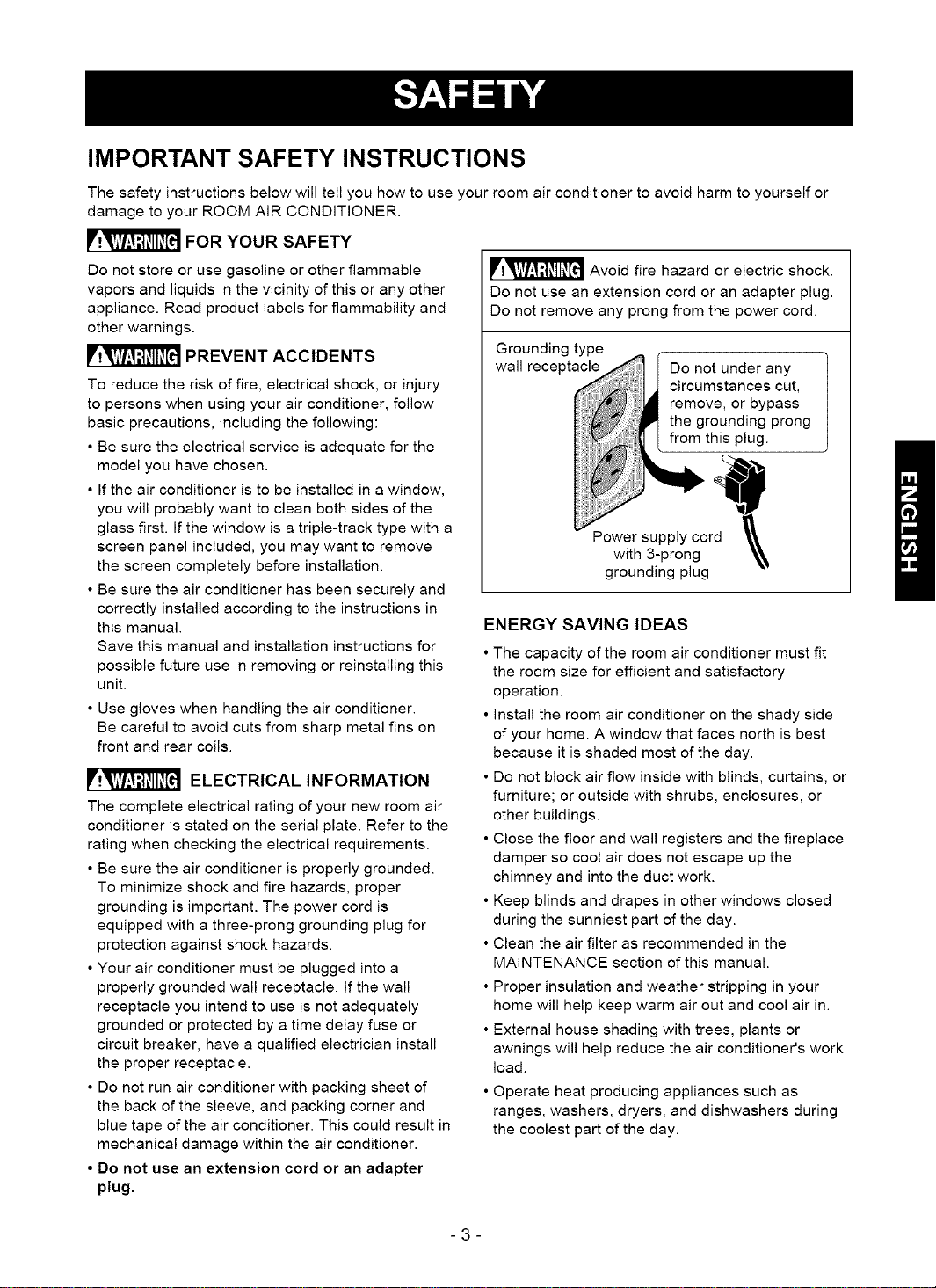
_ Avoid fire hazard or electric shock.
Do not use an extension cord or an adapter plug.
Do not remove any prong from the power cord.
Grounding type
wall receptacle
grounding plug
Do not under any
circumstances cut,
remove, or bypass
the grounding prong
from this plug.
ENERGY SAVING IDEAS
• The capacity of the room air conditioner must fit
the room size for efficient and satisfactory
operation.
• install the room air conditioner on the shady side
of your home. A window that faces north is best
because it is shaded most of the day.
• Do not block air flow inside with blinds, curtains, or
furniture; or outside with shrubs, enclosures, or
other buildings.
• Close the floor and wall registers and the fireplace
damper so cool air does not escape up the
chimney and into the duct work.
• Keep blinds and drapes in other windows closed
during the sunniest part of the day.
• Clean the air filter as recommended in the
MAINTENANCE section of this manual.
• Proper insulation and weather stripping in your
home will help keep warm air out and cool air in.
• External house shading with trees, plants or
awnings will help reduce the air conditioner's work
load.
• Operate heat producing appliances such as
ranges, washers, dryers, and dishwashers during
the coolest part of the day.
-3-
OBSERVEALL LOCAL CODES AND
ORDINANCES.
DO NOT, UNDER ANY CIRCUMSTANCES,
REMOVE THE POWER SUPPLY CORD
GROUND PRONG.
ELECTRICAL GROUND IS REQUIRED ON
THIS APPLIANCE.
A 208/230-volt 60 Hz, AC only, 15A fused and
properly grounded electrical supply is required.
A time delay fuse or time delay circuit breaker
is recommended. Use a dedicated circuit,
serving only this appliance.
DO NOT USE AN EXTENSION CORD.
RECOMMENDED GROUNDING METHOD
For your personal safety, this appliance must
be grounded. This appliance has a power
supply cord with a 3-prong grounding plug. To
minimize possible shock hazard, the cord must
be plugged into a mating grounding type wall
receptacle and grounded in accordance with
the National Electrical Code (ANSt/NFPA 70)
latest edition and all local codes and
ordinances. If a mating wall receptacle is not
available, it is the personal responsibility and
obligation of the customer to have a properly
grounded 3-prong wall receptacle installed by a
qualified electrician.
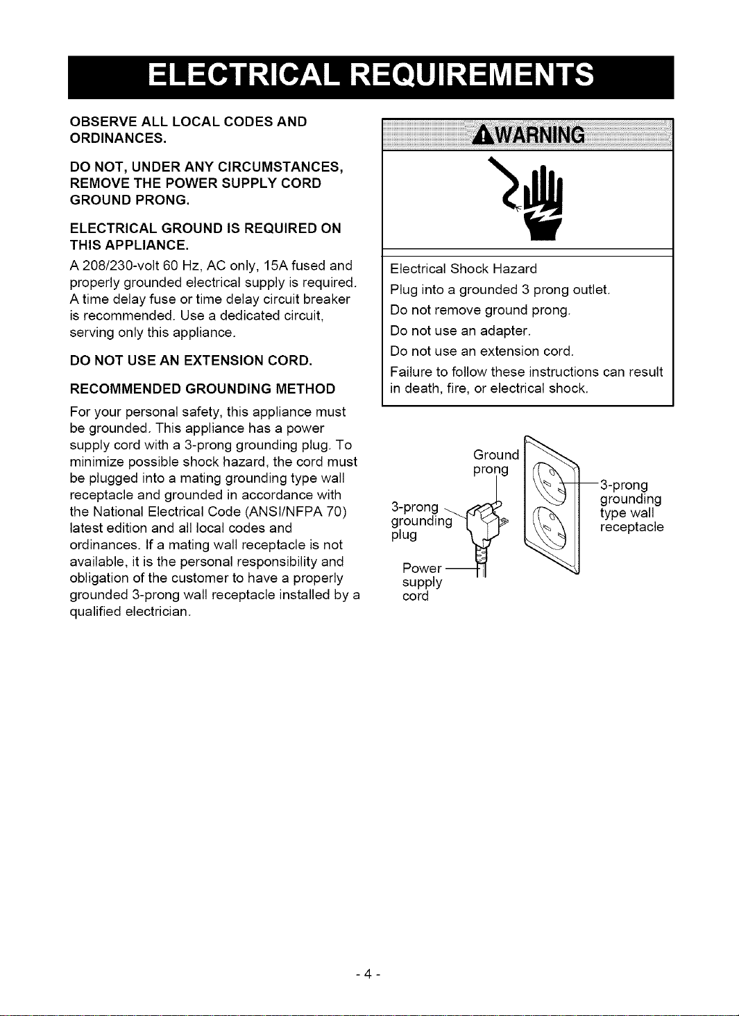
Electrical Shock Hazard
Plug into a grounded 3 prong outlet.
Do not remove ground prong.
Do not use an adapter.
Do not use an extension cord.
Failure to follow these instructions can result
in death, fire, or electrical shock.
Ground
prong I/! _ 'fl
/ 3-prong
_..k I \"--J I grounding
,J-prong _ I _ ] type wall
gg.rounalng k _'T'F I receptacle
Power_ "_
supply
cord
-4-
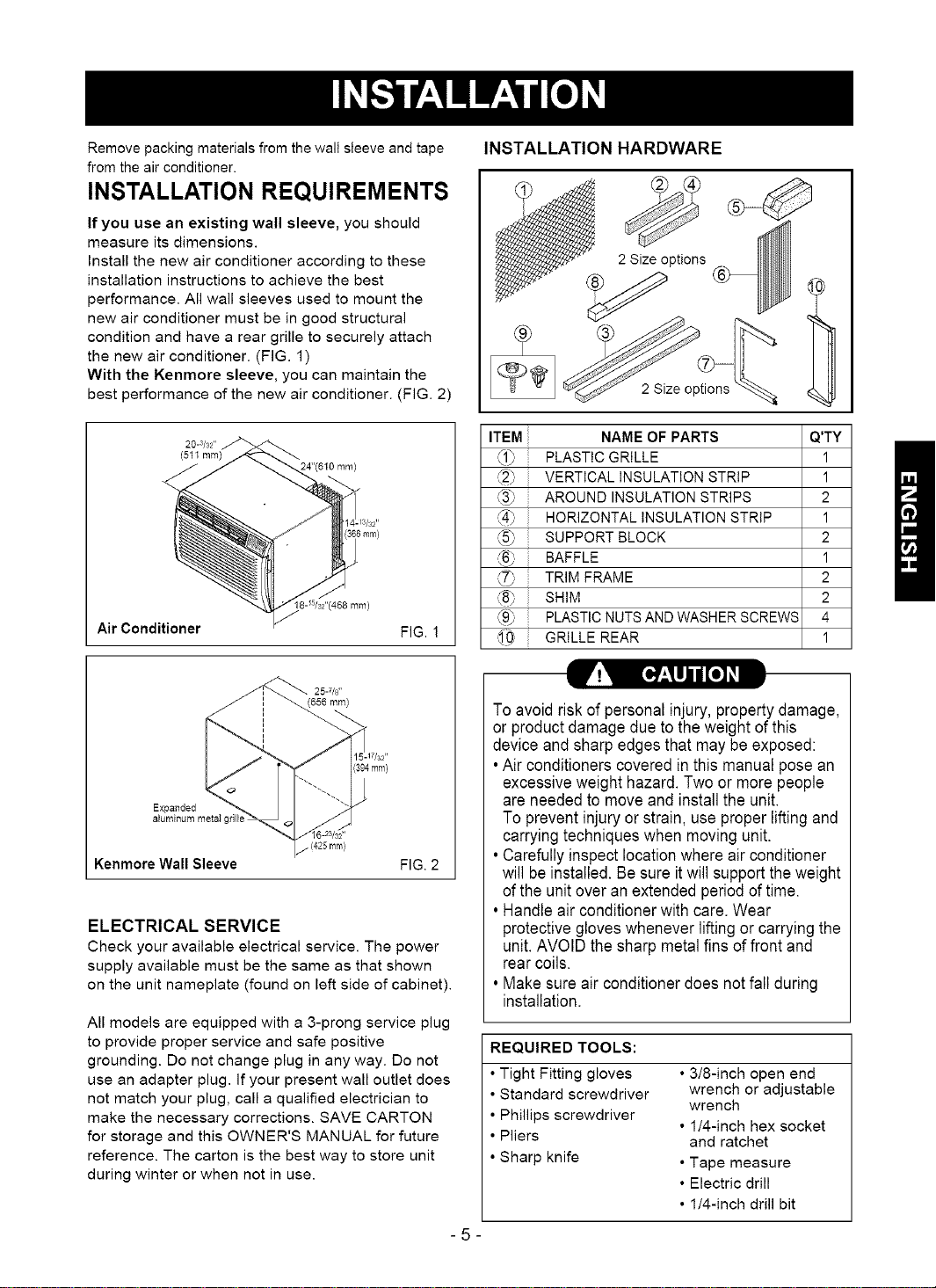
Remove packing materials from the wall sleeve and tape
from the air conditioner.
INSTALLATION REQUIREMENTS
If you use an existing wall sleeve, you should
measure its dimensions.
Install the new air conditioner according to these
installation instructions to achieve the best
performance. All wall sleeves used to mount the
new air conditioner must be in good structural
condition and have a rear grille to securely attach
the new air conditioner. (FIG. 1)
With the Kenmore sleeve, you can maintain the
best performance of the new air conditioner. (FIG. 2)
INSTALLATION HARDWARE
ptions
20-3/32"
(511 ram)
6 ram)
8-_5/s2"(468ram)
Air Conditioner
Expanded
aluminum metal grill
FIG. !
(394mm}
Kenmore Wall Sleeve FIG. 2
ELECTRICAL SERVICE
Check your available electrical service. The power
supply available must be the same as that shown
on the unit nameplate (found on left side of cabinet).
All models are equipped with a 3-prong service plug
to provide proper service and safe positive
grounding. Do not change plug in any way. Do not
use an adapter plug. If your present wall outlet does
not match your plug, call a qualified electrician to
make the necessary corrections. SAVE CARTON
for storage and this OWNER'S MANUAL for future
reference. The carton is the best way to store unit
during winter or when not in use.
ITEM
i PLASTIC GRILLE 1
\)
i VERTICAL INSULATION STRIP 1
HORIZONTAL INSULATION STRIP 1
AROUND
SUPPORT BLOCK 2
i BAFFLE 1
ii TRIM FRAME 2
SHIM 2
i PLASTIC NUTS AND WASHER SCREWS 4
i GRILLE REAR 1
NAME OF PARTS Q'TY
INSULATION STRIPS 2
To avoid riskof personal injury, property damage,
or product damage due to the weight of this
device and sharp edges that may be exposed:
•Air conditioners covered in this manual pose an
excessiveweight hazard. Two or more people
are needed to move and install the unit.
To prevent injury or strain, use proper lifting and
carrying techniques when moving unit.
• Carefully inspectlocation where air conditioner
will be installed. Be sure itwill support the weight
of the unitover anextended periodof time.
• Handle air conditioner with care. Wear
protective gloves whenever lifting or carryingthe
unit. AVOID the sharp metalfins of front and
rear coils.
• Make sure air conditioner does not fall during
installation.
REQUIRED TOOLS:
• Tight Fitting gloves
• Standard screwdriver
• Phillips screwdriver
• Pliers
• Sharp knife
• 3/8-inch open end
wrench or adjustable
wrench
• 1/4-inch hex socket
and ratchet
• Tape measure
• Electric drill
• 1/4-inch drill bit
-5-
INSTALLATION
We strongly recommend the removal of the
oldwall sleeve and the installationof a new
Kenmore Wall Sleeve,
If you decide to keep the existing wall sleeve,
you haveto redirect the louvers at the back of the
wall sleeve illustration. The use of pliers is
recommended. If you DO NOT redirect, you run
the risk of poor performance or product failure.
This is not covered under the terms of the
Kenmorewarranty.
• Pick a location which will allow the conditioned air
to blow into the area you want. Good installation
with special attention to the proper position of the
unit will lessen the chance that service will be
needed.
ITEMS IN INSTALLATION HARDWARE
You may not need all parts in the kit. Discard
unused parts
ITEM (inches)
Plastic grille
Vertical insulation strip
Around insulation Strips
Horizontal Insulation Strip
Support Block
Baffle
Shim
Trim Frame
Washer Screw
Nuts(Plastic)
Grille Rear
263/4 X 161/2
158/18 X 13/8X 13/8
671/8 X 13/8 X 25/32
5927/32 X 13/8 X 13/8
237/32 X 13/8 X 13/I8
13/4 X 13/8 X 45/18
14 x 41/2 x 1/8
1113/18X 1 X3/4
Qty.
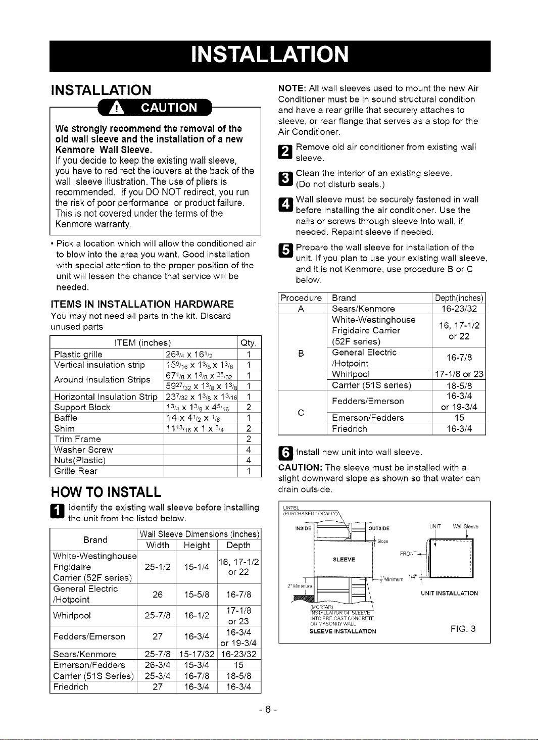
HOW TO INSTALL
H Identify the existing wall sleeve before installing
the unit from the listed below.
Brand
White-Westinghouse
Frigidaire
Carrier (52F series)
General Electric
/Hotpoint
Whirlpool 25-7/8
Fedders/Emerson 27
Sears/Kenmore 25-7/8
Emerson/Fedders 26-3/4
Carrier (51S Series) 25-3/4
Friedrich 27
Wall Sleeve Dimensions (inches)
Width
25-1/2
26
Height Depth
15-1/4 16, 17-1/2
15-5/8 16-7/8
16-1/2
16-3/4 16-3/4
15-17/32 16-23/32
15-3/4 15
16-7/8 18-5/8
16-3/4 16-3/4
or 22
17-1/8
or 23
or 19-3/4
NOTE: All wall sleeves used to mount the new Air
Conditioner must be in sound structural condition
and have a rear grille that securely attaches to
sleeve, or rear flange that serves as a stop for the
Air Conditioner.
_-'_ Remove old air conditioner from existing wall
sleeve.
_1 Clean the interior of an existing sleeve.
(Do not disturb seals.)
D Wall sleeve must be securely fastened in wall
before installing the air conditioner. Use the
nails or screws through sleeve into wall, if
needed. Repaint sleeve if needed.
_4J Prepare the wall sleeve for installation of the
unit. If you plan to use your existing wall sleeve,
and it is not Kenmore, use procedure B or C
below.
Procedure Brand Depth(inches)
A Sears/Kenmore 16-23/32
White-Westinghouse
Frigidaire Carrier 16, 17-1/2
(52F series)
1
1
1
1
1
2
1
2
B General Electric
/Hotpoint
Whirlpool 17-1/8 or 23
Carrier (51S series) 18-5/8
Fedders/Emerson
C
Emerson/Fedders 15
Friedrich 16-3/4
or 22
16-7/8
16-3/4
or 19-3/4
2
4
4
1
Q Install new unit into wall sleeve.
CAUTION: The sleeve must be installed with a
slight downward slope as shown so that water can
drain outside.
LINTEL
(PURCHASED LOCALLY)
INSIDE_=sope _OUTSIDE FRONT UNIT Wall Sleeve
2..rvli,_i,TiumII II _ _"Mini ...... 1i4" _ _" .....
{MORTAR)
INSTALLATION OF SLEEVE
INTO PRE CAST CONCRETE
OR MASONRY WALL
SLEEVEiNSTALLATION FIG. 3
UNIT INSTALLATION
-6-
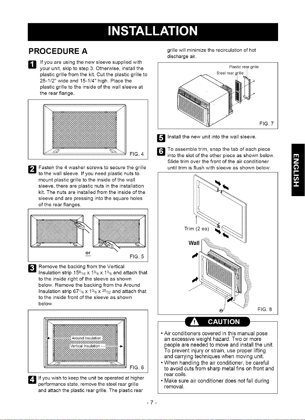
PROCEDURE A
_1 If you are using the new sleeve supplied with
your unit, skip to step 3. Otherwise, install the
plastic grille from the kit. Cut the plastic grille to
25-1/2" wide and 15-1/4" high. Place the
plastic grille to the inside of the wall sleeve at
the rear flange.
grille will minimize the recirculation of hot
discharge air.
Plastic rear grille
Steel rear c
FIG. 7
_4J Install the new unit into the wall sleeve.
FIG. 4
_"_ Fasten the 4 washer screws to secure the grille
to the wall sleeve. If you need plastic nuts to
mount plastic grille to the inside of the wall
sleeve, there are plastic nuts in the installation
kit. The nuts are installed from the inside of the
sleeve and are pressing into the square holes
of the rear flanges.
or
_J Remove the backing from the Vertical
Insulation strip 158/18 x 13/8 X 13/8 and attach that
to the inside right of the sleeve as shown
below. Remove the backing from the Around
Insulation strip 671/8 x 13/8 X 25/32 and attach that
to the inside front of the sleeve as shown
below.
FIG. 5
r_To assemble trim, snap the tab of each piece
into the slot of the other piece as shown below.
Slide trim over the front of the air conditioner
until trim is flush with sleeve as shown below.
Trim (2 ea)
Wall
"I
/
FIG. 8
FIG. 6
D If you wish to keep the unit be operated at higher
performance state, remove the steel rear grille
and attach the plastic rear grille. The plastic rear
•Air conditioners covered in this manual pose
an excessive weight hazard. Two or more
people are needed to move and install the unit.
To prevent injury or strain, use proper lifting
and carrying techniques when moving unit.
•When handling the air conditioner, be careful
to avoid cuts from sharp metal fins on front and
rear coils.
• Make sure air conditioner does not fall during
removal.
-7-
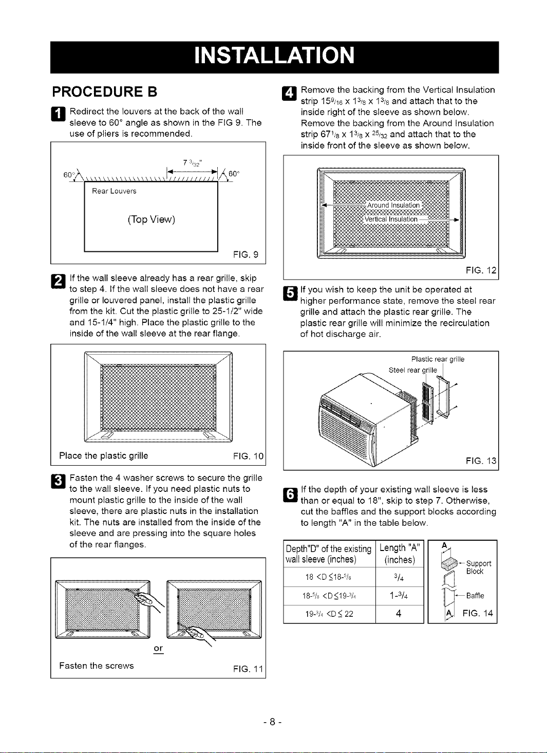
PROCEDURE B
H Redirect the louvers at the back of the wall
sleeve to 60 ° angle as shown in the FIG 9. The
use of pliers is recommended.
7 3132"
:_0 °
Rear Louvers
(Top View)
FIG. 9
I_lf the wall sleeve already has a rear grille, skip
to step 4. If the wall sleeve does not have a rear
grille or Iouvered panel, install the plastic grille
from the kit. Cut the plastic grille to 25-1/2" wide
and 15-1/4" high. Place the plastic grille to the
inside of the wall sleeve at the rear flange.
I_ Remove the backing from the Vertical Insulation
strip 159/18x 13/8x 13/8 and attach that to the
inside right of the sleeve as shown below.
Remove the backing from the Around Insulation
strip 671/8 x 13/8 X 25/32 and attach that to the
inside front of the sleeve as shown below.
FIG. 12
I_lf you wish to keep the unit be operated at
higher performance state, remove the steel rear
grille and attach the plastic rear grille. The
plastic rear grille will minimize the recirculation
of hot discharge air.
Plastic rear gritle
Steet rear (
Place the plastic grille
I[_ Fasten the 4 washer screws to secure the grille
to the wall sleeve. If you need plastic nuts to
mount plastic grille to the inside of the wall
sleeve, there are plastic nuts in the installation
kit. The nuts are installed from the inside of the
sleeve and are pressing into the square holes
of the rear flanges.
or
Fasten the screws
FIG. 10
FIG. 11
ir_lf the depth of your existing wall sleeve is less
than or equal to 18", skip to step 7. Otherwise,
cut the baffles and the support blocks according
to length "A" in the table below.
Depth"D"oftheexisting
wallsleeve(inches)
18 <D_<18-%
18-5/8 <D <19-3/4
19-3/4<D _<22
Length"A"
(inches)
3/4
1-3/4
4
-8-
FIG. 13
_ upport
Block
1_[ - Baffle
FIG. 14
PROCEDURE B
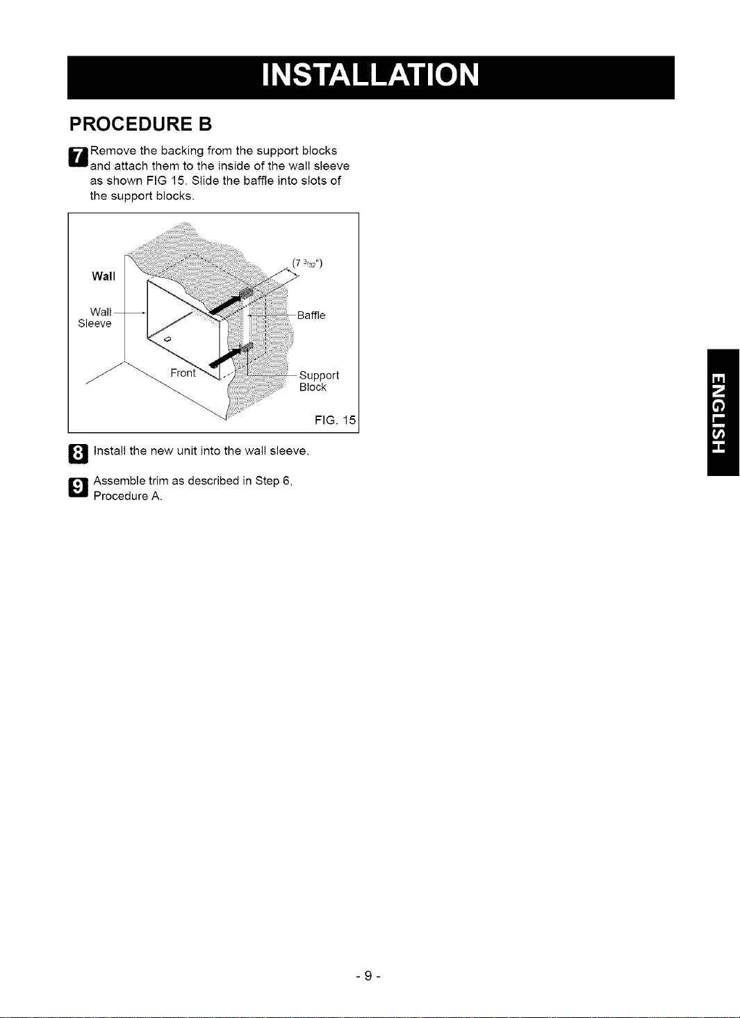
WRemove the backing from the support blocks
and attach them to the inside of the wall sleeve
as shown FIG 15. Slide the baffle into slots of
the support blocks.
Wall
Wall
Sleeve
f_ Install the new unit into the wall sleeve.
Q Assemble trim as described in Step 6,
Procedure A.
(7 3/32")
Block
FIG. 15
-9-
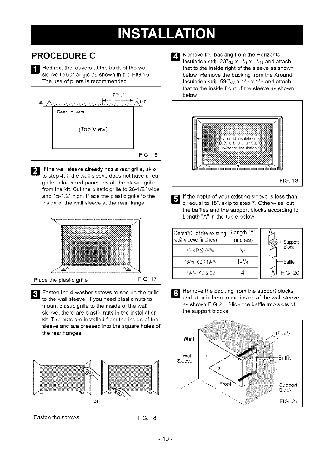
PROCEDURE C
H Redirect the louvers at the back of the wall
sleeve to 60 ° angle as shown in the FIG 16.
The use of pliers is recommended.
73/32"
Lt0°
Rear Louvers
(Top View)
FIG. 16
I_lf the wall sleeve already has a rear grille, skip
to step 4. If the wall sleeve does not have a rear
grille or Iouvered panel, install the plastic grille
from the kit. Cut the plastic grille to 26-1/2" wide
and 15-1t2" high. Place the plastic grille to the
inside of the wall sleeve at the rear flange.
_J Remove the backing from the Horizontal
insulation strip 237/82 x 13/8 x 13/18and attach
that to the inside right of the sleeve as shown
below. Remove the backing from the Around
insulation strip 5927/32 x 13/8 x 13/8 and attach
that to the inside front of the sleeve as shown
below.
If the depth of your existing sleeve is less than
El
or equal to 18", skip to step 7. Otherwise, cut
the baffles and the support blocks according to
Length "A" in the table below.
FIG. 19
Place the plastic grille
I[_ Fasten the 4 washer screws to secure the grille
to the wall sleeve. If you need plastic nuts to
mount plastic grille to the inside of the wall
sleeve, there are plastic nuts in the installation
kit. The nuts are installed from the inside of the
sleeve and are pressed into the square holes of
the rear flanges.
or
FIG. 17
Depth"D"of the existing
wailsleeve(inches)
18 <D_<18-%
18-5/8<D <19-3/4
19-3/4<D _<22
ir_ Remove the backing from the support blocks
and attach them to the inside of the wall sleeve
as shown FIG 21. Slide the baffle into slots of
the support blocks
Length"A"
(inches)
3/4
1-8/4
4
_ upport
Block
'_F Baffle
IG. 20
7 3'32")
Wall
Wall
Sleeve
/ _ Block
FIG. 21
Fasten the screws FIG. 18
-10-
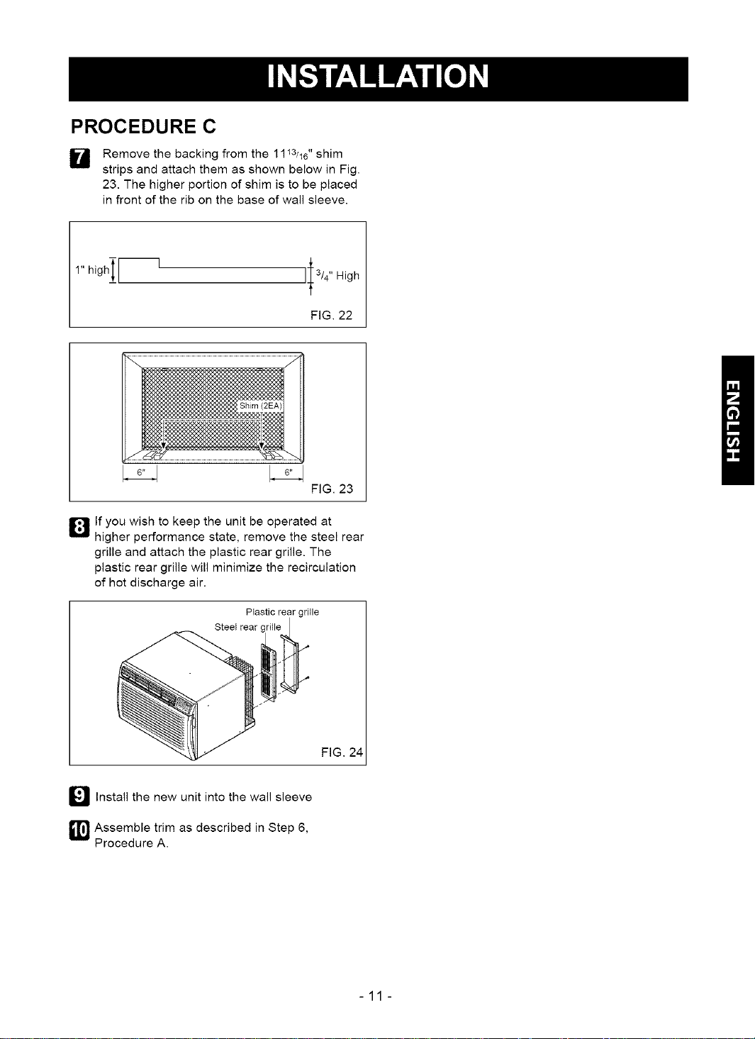
PROCEDURE C
W Remove the backing from the 1113/16" shim
strips and attach them as shown below in Fig.
23. The higher portion of shim is to be placed
in front of the rib on the base of wall sleeve.
h,4--' 'I'"0h
FIG. 22
I 6"1
FIG. 23
D If you wish to keep the unit be operated at
higher performance state, remove the steel rear
grille and attach the plastic rear grille. The
plastic rear grille will minimize the recirculation
of hot discharge air.
Plastic rear grille
Steel rear
_'_ Install the new unit into the wall sleeve
_1_ Assemble trim as described in Step 6,
Procedure A.
FIG. 24
-11-
HOW AND WHY
Your room air conditioner provides the following
functions to make hot weather living more
comfortable:
• Cools and circulates room air.
• Lowers humidity by removing excess moisture.
• Filters out summertime dust, dirt, and some
airborne impurities.
The air conditioner performs these functions by
drawing room air through a filter which traps dust
and dirt particles. The air then passes over a
cooling coil which refrigerates the air and removes
excess moisture. The same air is then returned to
the room- cooler, drier, and cleaner. Moisture
removed from the room air is carried to the outside
and evaporated.
Your air conditioner is designed to be easy to
operate and to provide plenty of cooling power.
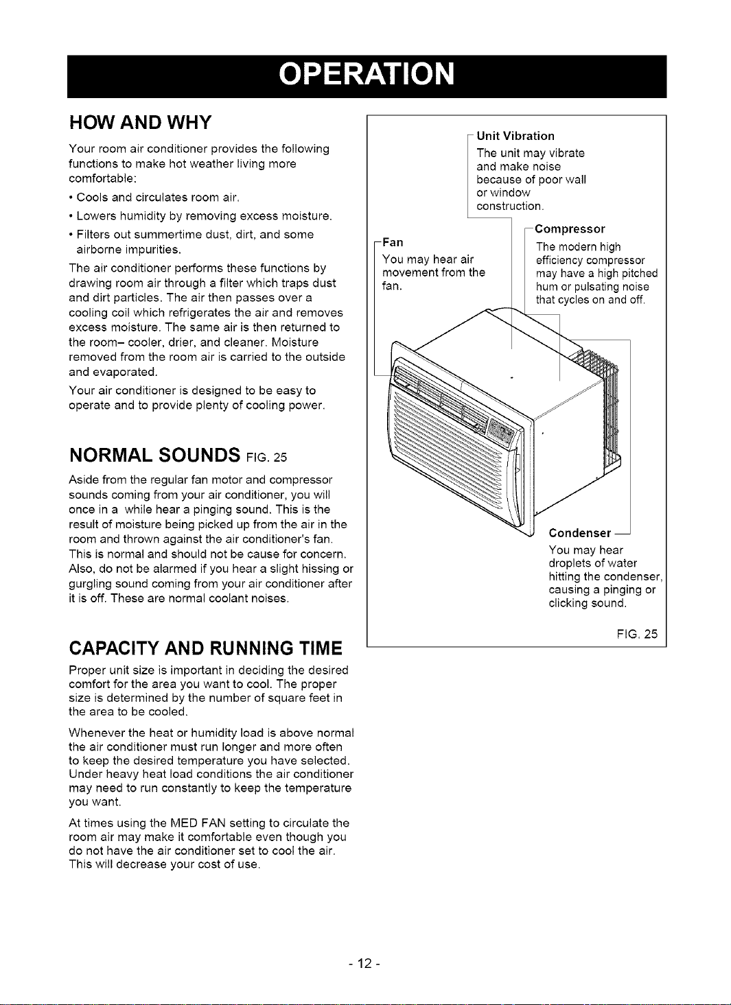
NORMAL SOUNDS FIG.25
Aside from the regular fan motor and compressor
sounds coming from your air conditioner, you will
once in a while hear a pinging sound. This is the
result of moisture being picked up from the air in the
room and thrown against the air conditioner's fan.
This is normal and should not be cause for concern.
Also, do not be alarmed if you hear a slight hissing or
gurgling sound coming from your air conditioner after
it is off. These are normal coolant noises.
Unit Vibration
The unit may vibrate
and make noise
because of poor wall
or window
construction.
Compressor
Fan The modern high
You may hear air efficiency compressor
movement from the may have a high pitched
fan. hum or pulsating noise
that cycles on and off.
Condenser
You may hear
droplets of water
hitting the condenser
causing a pinging or
clicking sound.
CAPACITY AND RUNNING TIME
Proper unit size is important in deciding the desired
comfort for the area you want to cool. The proper
size is determined by the number of square feet in
the area to be cooled.
Whenever the heat or humidity load is above normal
the air conditioner must run longer and more often
to keep the desired temperature you have selected.
Under heavy heat load conditions the air conditioner
may need to run constantly to keep the temperature
you want.
At times using the MED FAN setting to circulate the
room air may make it comfortable even though you
do not have the air conditioner set to cool the air.
This will decrease your cost of use.
FIG. 25
-12-
 Loading...