

Kenmore 73515, 73811, 73819 Owner's Manual
Kenmore
OWNIR'$ I/tANUAL
GAS RANGE
models 73511
73515
73811
73819
CONTENTS
INSTALLATION
Before You Begin
Dimensions and Clearances
Important Safety Instructions
Normal Installation Steps
How to Convert the Range for Use with LP Gas
CARE AND USE
Important Safety Instructions
Features of Your Range
Clock and Electronic Controls
Surface Cooking
Using Your Oven
Baking
Roasting
Broiling
Self-Cleaning Oven
Care and Cleaning
Minor Adjustments You Can Make
PROBLEM SOLVER
The Problem Solver lists causes of minor operating
problems that you can correct yourself.
WARRANTY
FOR YOUR SAFETY
if you smel gas:
1. Open windows.
2. Don't touch egectrical switches.*
3. Extinguish any open flame.
4. lmmediate0y cal your gas suppler.
*Don't turn electric switches on or off because sparks
may ignite the gas,
FOR YOUR SAFETY
Do not store or use gasoine or
other flammabne vapors and iquids
in the vicinBty of this or any other
epplence.
WARNING
improper instalaton, adjustment,
alteration, seFviceor maintenance
can cause injuryor property dam-
age. Refer to this manual For assis-
tance or additional information,
consul a quelled instaler, service
agency, manufacturer (dealer) or
the gas suppler.
IHSTALLATIOH IIISTIUOTION$
BEFORE YOU BEGIN
Road those instructions comploteIy and
carefulDy.
IMPORTANT: Save theso instructions for the
local electricaa inspector's use.
INSTALLER: Leave these instructions with the
appliance after instalation is completed.
OWNER: Koep this Use and Caro Guide and
the lnstalation instructions for future use.
This applance must be properly grounded.
CAUTION
Do not attempt to operate the oven of this
range during a power falure.
iMPORTANT
Remove al packing material and literature
from oven before connecting gas and electri-
cal supply to range.
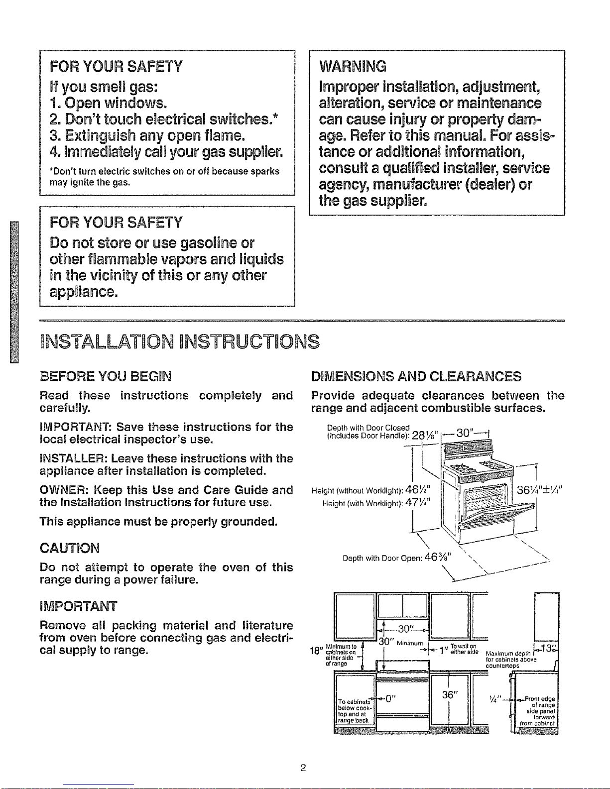
DIMENSnON$ AND CLEARANCES
Provide adequate clearances between the
range and adjacent combustibJe surfaces.
Depth wth Door Closed
(Includes Door Handle) 28¼
Height (without Worklight): 46½"
Height (with Worklight): 47¼"
36¼,,+1/_,,
Depth with Door Open: 46%" "\ f_
[ for Cabinets _bove
•
_"0" Y4" Front edge
II I ill | ! of range
Ib._o*cook.}_ II t tlL U sid.pa._=
,,o.a.d.,l I_
IMPORTANT SAFETY nNSTRUCT ONS
Installation of this range must conform with local
codes, or in the absence of local codes, with the
National Fuel Gas Code, ANSa Z223, latest edition.
This range has been design-certified by the American
Gas Association according to ANSI Z21 1, latest edi-
tion As with any appliance using gas and generating
heat, there are certain safety precautions you should
follow. You will find these precautions on pages t3-16
Read them carefully
o Have your range installed by a qualified installer or
service technician.
o Your range must be electrically grounded in accor-
dance with local codes or, in the absence of local
codes, in accordance with the National Electrical
Code (ANSl/NFPA 70, latest edition) See Grounding
on page 6.
o Before installing your range on linoleum or any
other synthetic floor covering, make sure the floor
covering can withstand 180°R without shrinking,
warping or discoloring. Do not install the range over
carpeting unless a sheet of 1/4-inch4hick plywood
or similar insulator is placed between the range and
carpeting
o Make sure the walt coverings around the range can
withstand heat generated by the range up to 200°F.
o Avoid placing cabinets above the range. To reduce
the hazard caused by reaching over the open flames
of operating burners, install over the range a ventila-
tion hood that projects forward at least 5 inches
beyond the front of the cabinets.
The ventilating hood must be constructed of sheet
metal not less than 0.0122 inch thick (No. 28 US.
Standard gauge). Install above the cooking top with a
clearance of not less than 1/4 inch between the hood
and the underside of the combustible material or
metal cabinet. The hood must be at least as wi'de as
the appliance and centered over the appliance.
Clearance between the cooking surface and the venti-
lation hood surface MUST NEVER BE LESS THAN
24 INCHES.
• If cabinets are placed above the range, allow a mini-
mum clearance of 30 inches between the cooking sur-
face and the bottom of unprotected cabinets
o If a 30-inch clearance between cooking surface and
overhead combustible material or metal cabinets can-
not be maintained, protect the underside of the cabi-
nets above the cooking top with not less than 1/4-inch
insulating millboard covered with sheet metal not less
than 0.0122 inch thick (No 28 US. Standard gauge)
• Clearance between the cooking surface and protect-
ed cabinets MUST NEVER BE LESS THAN 24
INCHES, The vertical distance from the plane of the
cooking surface to the bottom of adjacent overhead
cabinets extending closer than 1 inch to the plane of
the range sides must not be less than 18 inches, (See
diagram on page 2.)
Caution: Items of interest to children should not be
stored in cabinets above a range or on the backsplash
of a range--children climbing on the range to reach
items could be seriously injured..
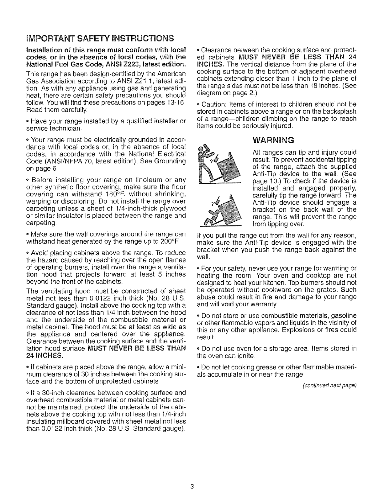
WARNING
All ranges can tip and injury could
result.. To prevent accidental tipping
of the range, attach the supplied
Anti-Tip device to the wall. (See
page l&) To check if the device is
installed and engaged properly,
carefully tip the range forward.. The
Anti-Tip device should engage a
bracket on the back wall of the
range. This will prevent the range
from tipping over.
If you pull the range out from the wall for any reason,
make sure the Anti-Tip device is engaged with the
bracket when you push the range back against the
wall.
o For your safety, never use your range for warming or
heating the room. Your oven and cooktop are not
designed to heat your kitchen.. Top burners should not
be operated without cookware on the grates. Such
abuse could result in fire and damage to your range
and will void your warranty.
o Do not store or use combustible materials, gasoline
or other flammable vapors and liquids in the vicinity of
this or any other appliance Explosions or fires could
result.
• Do not use oven for a storage area. Items stored in
the oven can ignite.
• Do not let cooking grease or other flammable materi-
als accumulate in or near the range
(continued next page)
Installation instructions (continued)
GENERAL
• See Dimensions and Clearances on page 2 for all
rough-in and spacing dimensions. These dimensions
must be met for safe use of your range.. The location of
the electrical outlet and pipe opening shown on page 5
may be adjusted to meet specific requirements.
. The range may be placed with 0" clearance (flush) at
the back wall and side walls of the range.
LOCATION
Do not locate the range where it may be subject to
strong drafts. Any openings in the floor or walt behind
the range should be sealed. Make sure the openings
around the base of the range that supply fresh air for
combustion and ventilation are not obstructed by car-
peting or woodwork.
PROTECT YOUR FLOOR
Your range, like many other household items, is heavy
and can settle into soft floor coverings such as cush-
ioned vinyl or carpeting. Use care when moving the
range on this type of flooring. It is recommended that
the following simple and inexpensive instructions be
followed to protect your floor.
The range should be installed on a sheet of plywood
(or similar material) as follows: When the floor cover-
ing ends at the front of the range, the area that the
range will rest on should be built up with plywood to
the same level or higher than the floor covering.. This
will allow the range to be moved for cleaning or ser-
vicing.
MODEL AND SERDALNUMBER LOCATION
The model and serial numbers are on a label located
on the front frame of the range, behind either the oven
door or the storage drawer.
TOOLS YOU WILL NEED
o Phillips screwdriver
• Pencil and ruler
o Two pipe wrenches (one for backup)
o 1¾" open-end or adjustable wrench
o 3/16" open-end or socket wrench
o Nut driver
In addition, for LP gas conversion, you will need:
° 5/16" open-end wrench
• 1/2" open-end wrench
ADDaTIONAL MATERIALS YOU MAY NEED
- Gas line shutoff valve
° Pipe joint sealant or pipe thread tape with Teflon*
that resists action of natural and LP gases
o Flexible metal appliance connector (1/2" IDI)_ A 5-
foot length is recommended for ease of installation but
other lengths are acceptable. Never use an old con-
nector when installing a new range..
o Flare union adapter for connection to gas supply line
(3/4" or 1/2" NPT x 1/2" ID.)
o Flare union adapter for connection to pressure regu-
lator on range (1/2" NPT x 1/2" !.D.)
*Teflon: Registered trademark of DuPont
PREPARATION
o Remove all tape and packaging. Be sure to remove
plastic film that covers some chrome parts (around
oven doors, side trim).
° Take the accessory pack out of the oven.
. Check to be sure that no range parts have come
loose during shipping..
NORMAL INSTALLATION STEPS
Provide Adequate Gas Supply
The range is designed to operate at a pressure of 4
inches of water column on natural gas or, if designed
for LP gas (propane or butane), 10 inches of water
column. Make sure the range is supplied with the type
of gas for which it is designed If, at any time in the
future, the range is to be supplied with a different type
of gas, conversion adjustments must be made by a
qualified service technician before attempting to oper-
ate the range on that gas.
For proper operation, the pressure of natural gas sup-
plied to the regulator must be between 4 and 13 inch-
es of water column For LP gas, the pressure supplied
must be between 10 and 13 inches of water column
When checking for proper operation of the regulator,
the inlet pressure must be at least t inch greater than
the operating (manifold) pressure as given above. The
pressure regulator located at the inlet of the range
manifold must remain in the supply fine regardless of
whether natural or LP gas is being used A flexible
metal appliance connector used to connect the range
to the gas supply line should have an tDo of 1/2" and
be 5 feet in length (shorter and longer lengths are
acceptable) for ease of installation
2
Connect the Range to Gas
Before disconnecting the old range, shut off the main
gas supply valve and leave it off until new hook-up
has been completed
Because hard piping restricts movement of the range,
the use of an AoG.A.-certified flexible metal appliance
connector is recommended unless local codes require
a hard-piped connection Never use an old connector
when installing a new range
To prevent gas leaks, wrap pipe thread tape with
Teflon* around, or put pipe joint compound on, a!l
male (external) pipe threads
"Teflon: Registered trademark of DuPont
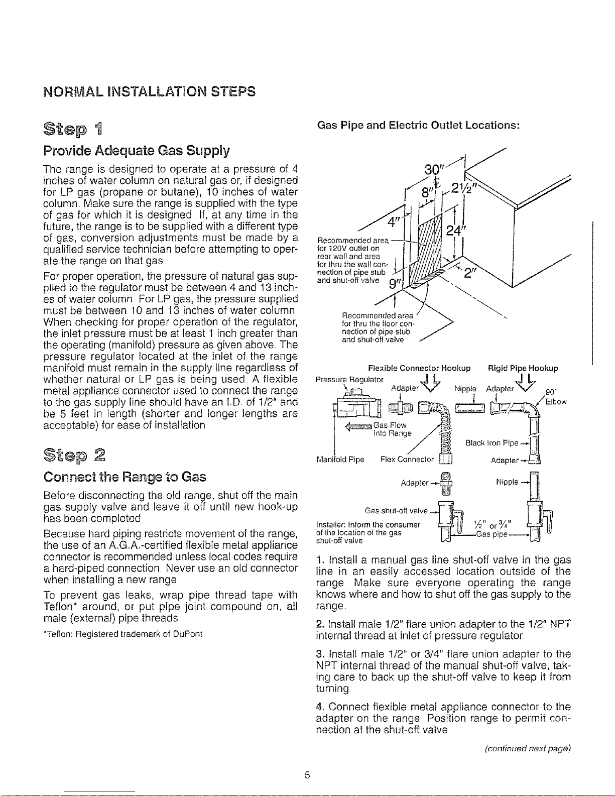
Gas Pipe and Electric Outlet Locations:
for t20V outlet on
rear waif and area
ler thru the wall con-
nection of pipe stub
and shut-off valve
Recommc _
for thru tile floor con-
nection of pipe stub
/
and shut-off valve .
Flexible Connector Hookup Rigid Pipe Hookup
Pressure Regulator
"_ _L, Adapter4-_ "_ Nipp,e Adapter4J '_ 90"
. Elbow
Gas F1ow
tale Range _ -_lll
Manifold Pipe Flex Connector Adapter
Adapter _ Nipple
Gassh°"°'va've-- 'kl J
Installer: _nform the consumer _ Ill 1/2" or 3_,, _ lit
of the local!on of the gas Gas i e---._
shut-off valve _ P p "_ _
1. Install a manual gas line shut-off valve in the gas
line in an easily accessed location outside of the
range Make sure everyone operating the range
knows where and how to shut off the gas supply to the
range,
2. Install male 1/2" flare union adapter to the 1/2" NPT
internal thread at inlet of pressure regulator.
3. Install male I/2" or 3/4" flare union adapter to the
NPT internal thread of the manual shut-off valve, tak-
ing care to back up the shut-off valve to keep it from
turning
4. Connect flexible metal appliance connector to the
adapter on the range. Position range to permit con-
nection at the shut-off valve
(continued next page)
5
Installation nstructions cont nue¢
5. When all connections have been made, make sure
all range controls are in the off position and turn on the
main gas supply valve,. Use a liquid leak detector at all
joints and connections to check for leaks in the system.,
CAUTION: DO NOT USE A FLAME TO CHECK
FOR GAS LEAKS.
When using test pressures greater than 1/2 psig to
pressure-test the gas supply system of the residence,
disconnect the range and individual shut-off valve
from the gas supply piping_ When using test pres-
sures of 1/2 psig or less to test the gas supply system,
simply isolate the range from the gas supply system
by closing the individual shut-off valve_
$2e 3
Egectrica Connections
Electrical Requirements:
120-volt, 60-Hz, properly grounded branch circuit pro-
tected by a 15-amp or 20-amp circuit breaker or time-
delay fuse.
Extension Cord Cautions:
Because of potential safety hazards associated with
certain conditions, we strongly recommend against
the use of an extension cord. However, if you still elect
to use an extension cord, it is absolutely necessary
that it be a UL-listed, 3-wire grounding-type appliance
extension cord and that the current carrying rating of
the cord in amperes be equivalent to, or greater than,
the branch circuit rating
Grounding--IMPORTANT (Please read carefully):
FOR PERSONAL SAFETY, THIS APPLIANCE MUST
BE PROPERLY GROUNDED.
The power cord of this appliance is equipped with a
three-prong (grounding) plug that mates with a stan-
dard three-prong grounding wall receptacle to mini-
mize the possibility of electric shock hazard from this
appliance.
The customer should have the wall receptacle and cir-
cuit checked by a qualified electrician to make sure
the receptacle is properly grounded,,
Where a standard two-prong wall receptacle is
encountered, it is the personal responsibility and obli-
gation of the customer to have it replaced with a prop-
erly grounded three-prong wall receptacle,.
DO NOT, UNDER ANY CIRCUMSTANCES, CUT OR
REMOVE THE THIRD (GROUND) PRONG FROM
THE POWER CORD.
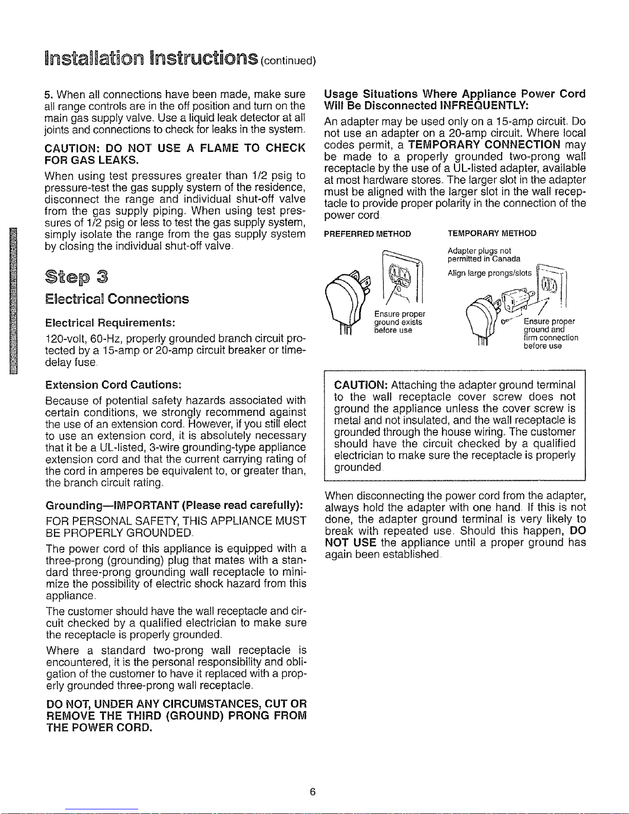
Usage Situations Where Appliance Power Cord
Will Be Disconnected INFREQUENTLY:
An adapter may be used only on a 15-amp circuit^ Do
not use an adapter on a 20-amp circuit. Where local
codes permit, a TEMPORARY CONNECTION may
be made to a properly grounded two-prong wall
receptacle by the use of a UL-listed adapter, available
at most hardware stores. The larger slot in the adapter
must be aligned with the larger slot in the walt recep-
tacle to provide proper polarity in the connection of the
power cord
PREFERRED METHOD TEMPORARY METHOD
_ nsurepropl'_r
ground exists
before use
Adapter plugs not
permitted in Canada
Align largo prongs/slots _:',_
\ )),/ _ _ Ensure proper
\_ ftJ ground and
firm connection
"' before use
CAUTION: Attaching the adapter ground terminal
to the wall receptacle cover screw does not
ground the appliance unless the cover screw is
metal and not insulated, and the wail receptacle is
grounded through the house wiring. The customer
should have the circuit checked by a qualified
electrician to make sure the receptacle is properly
grounded
When disconnecting the power cord from the adapter,
always hold the adapter with one hand If this is not
done, the adapter ground termina! is very likely to
break with repeated use. Should this happen, DO
NOT USE the appliance until a proper ground has
again been established
UsageSituations Where Appliance Power Cord
Will BeDisconnectedFREQUENTLY:
Do not use an adapter plug in these situations
because disconnectingof the power cord places
unduestrainonthe adapterandleadsto eventualfail-
ure of the adapter groundterminal,The customer
shouldhave thetwo-prongwall receptaclereplaced
withathree-prong(grounding)receptaclebya quali-
fiedelectricianbeforeusingtheappliance,
The installationof appliancesdesignedfor mobile
homeinstallationmustconformwiththe Manufactured
Home Constructionand Safety Standard,Title 24
CFR, Part3280 (formerlythe FederalStandardfor
MobileHomeConstructionandSafety,Title24,HUD,
Part 280)or,when such standardis not applicable,
theStandardforManufacturedHomeInstallations,lat-
est edition(ManufacturedHomeSites,Communities
and Set-Ups),ANSI A225 t, latest edition,or with
localcodes
Electrical Disconnect
1. Locate disconnect
plug at left rear of
burner box on the
range back,.
2. Pinch sides of con-
nector and pull out of
range back.
$2e 4
Sea the Openings
Seal any openings in the wall behind the range and in
the floor under the range when hookups are completed.
Check Ugnition of Surface Burners
Operation of all cooktop and oven burners should be
checked after range and gas supply lines have been
carefully checked for leaks,
Push in one of the surface burner controls and turn it
to the LITE position. You will hear a snapping sound
indicating proper operation of the spark module. Once
the air has been purged from the supply lines, burners
should light within 4 seconds. After burner lights,
rotate knob out of the LITE position. Try each burner
in succession until all burners have been checked.
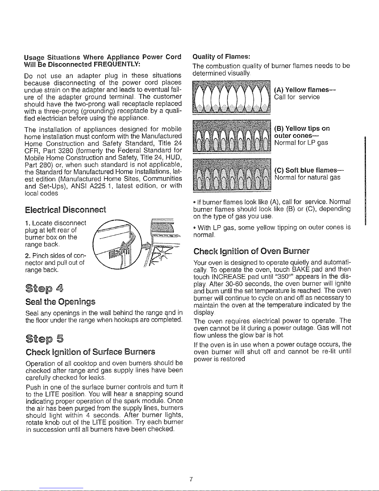
Quality of Flames:
The combustion quality of burner flames needs to be
determined visually
(A) Yellow flames--
Call for service
(B) Yellow tips on
outer cones--
Normal for LP gas
(C) Soft blue flames--
Normal for natural gas
• If burner flames look like (A), call for service° Normal
burner flames should look like (B) or (C), depending
on the type of gas you use
. With LP gas, some yellow tipping on outer cones is
normal°
Check Bgnition of Oven Burner
Your oven is designed to operate quietly and automati-
cally To operate the oven, touch BAKE pad and then
touch iNCREASE pad until "350 °'' appears in the dis-
play After 30-60 seconds, the oven burner will ignite
and burn until the set temperature is reached. The oven
burner will continue to cycle on and off as necessary to
maintain the oven at the temperature indicated by the
display.
The oven requires electrical power to operate., The
oven cannot be lit during a power outage. Gas wilt not
flow unless the glow bar is hot.
tf the oven is in use when a power outage occurs, the
oven burner will shut off and cannot be re-lit until
power is restored
nstaHationInstructions continuedl
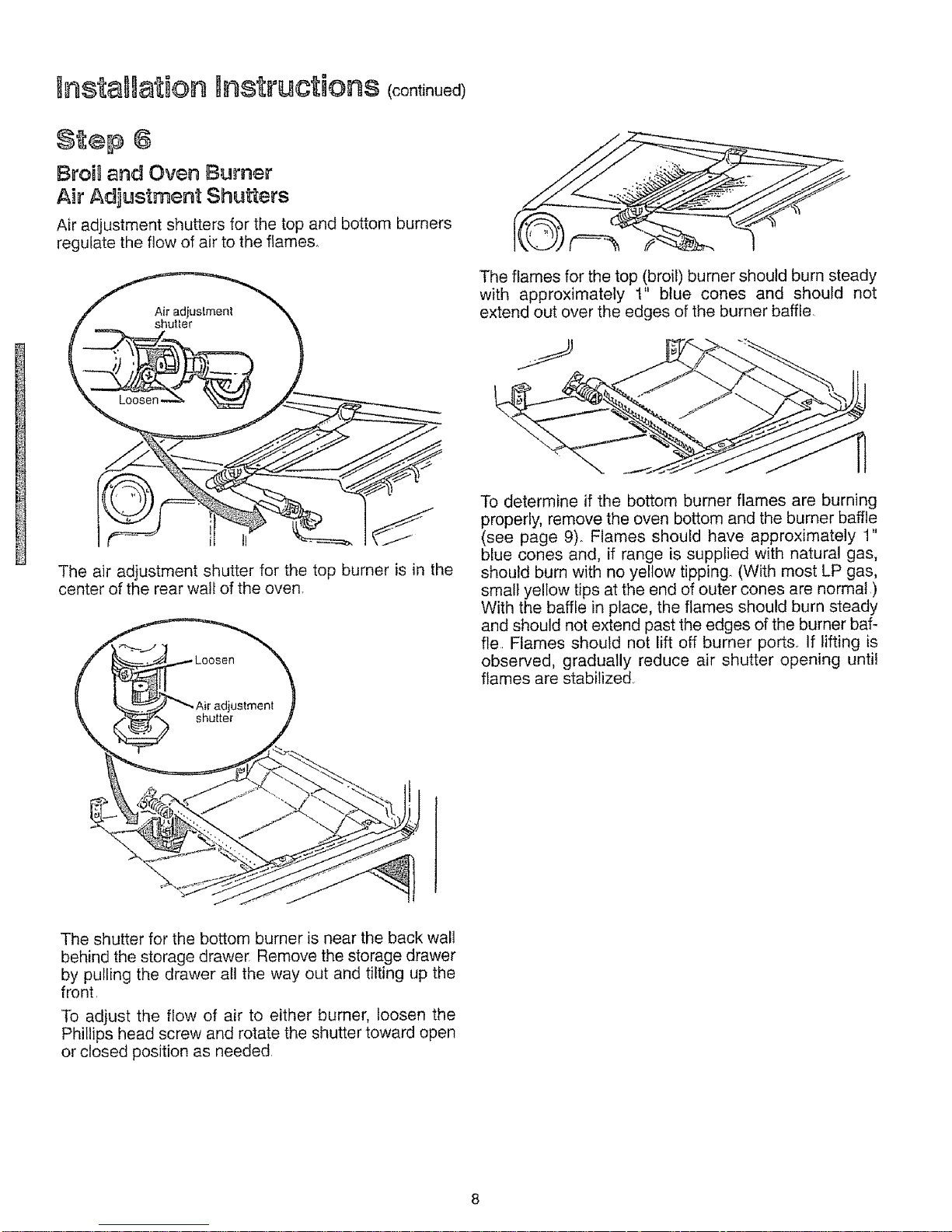
Broal end Oven Burner
Air Adjustment Shutters
Air adjustment shutters for the top and bottom burners
regulate the flow of air to the flames_
i
The air adjustment shutter for the top burner is in the
center of the rear wall of the oven.
The flames for the top (broil) burner should burn steady
with approximately t" btue cones and should not
extend out over the edges of the burner baffle
To determine if the bottom burner flames are burning
properly, remove the oven bottom and the burner baffle
(see page 9). Flames should have approximately 1"
blue cones and, if range is supplied with natural gas,
should burn with no yellow tipping. (With most LP gas,
small yellow tips at the end of outer cones are normal )
With the baffle in place, the flames should burn steady
and should not extend past the edges of the burner baf-
fle Flames should not !ift off burner ports. If lifting is
observed, gradually reduce air shutter opening until
flames are stabilized.
The shutter for the bottom burner is near the back wall
behind the storage drawer Remove the storage drawer
by pufling the drawer all the way out and tilting up the
front.
To adjust the flow of air to either burner, loosen the
Phillips head screw and rotate the shutter toward open
or closed position as needed.
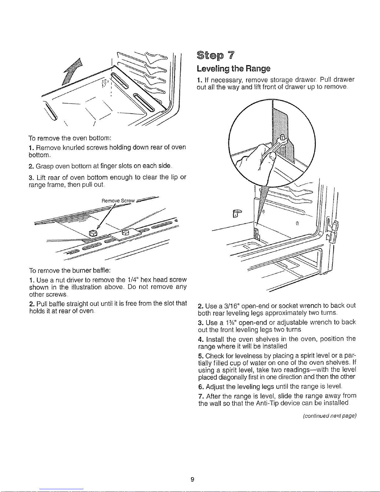
Toremovetheovenbottom:
1.Removeknurledscrewsholdingdownrearof oven
bottom.
2.Graspovenbottomatfingerslotsoneachside
3. Lift rearof ovenbottomenoughtoclear thelip or
rangeframe,thenpullout.
Remove Screw
To remove the burner baffle:
1. Use a nut driver to remove the 1/4" hex head screw
shown in the illustration above. Do not remove any
other screws
2. Pull baffle straight out until it is free from the slot that
holds it at rear of oven.
$1 ep ?
Leveling the Range
1. If necessary, remove storage drawer. Pull drawer
out all the way and lift front of drawer up to remove.
2. Use a 3/16" open-end or socket wrench to back out
both rear leveling legs approximately two turns,
3. Use a 1%" open-end or adjustable wrench to back
out the front leveling legs two turns
4. Install the oven shelves in the oven, position the
range where it will be installed
5. Check for levelness by placing a spirit level or a par-
tially filled cup of water on one of the oven shelves° If
using a spirit level, take two readings--with the level
placed diagonally first in one direction and then the other
6, Adjust the leveling legs until the range is level.
7. After the range is level, slide the range away from
the wall so that the Anti-Tip device can be installed
(continued ne_t page)
nsta Uation Instructions (continue€
9÷p 8
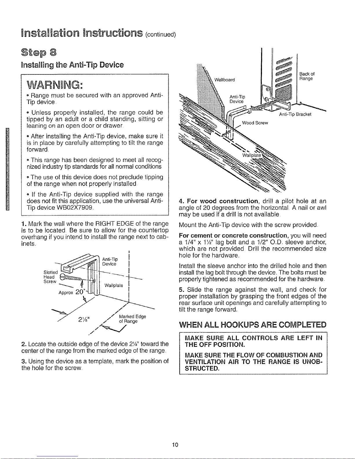
BnstaHing the Anti-Tip Device
WARNING:
o Range must be secured with an approved Anti-
Tip device,
o Unless properly installed, the range could be
tipped by an adult or a child standing, sitting or
leaning on an open door or drawer
o After installing the Anti-Tip device, make sure it
is in place by carefully attempting to tilt the range
forward
o This range has been designed to meet all recog-
nized industry tip standards for all normal conditions
o The use of this device does not preclude tipping
of the range when not properly installed
• If the Anti-Tip device supplied with the range
does not fit this application, use the universal Anti-
Tip device WB02X7909,
1. Mark the wall where the RIGHT EDGE of the range
is to be located Be sure to allow for the countertop
overhang if you intend to install the range next to cab-
inets.,
|
An,i-Tip1
-" I]Device ]
Slotled _ t !lt-:_._.._
Head _3_,,_, UIj, 1I
crow l 1-Tl!Wo,,p,a,o]
Appro×20 _dZL[J_ I
7 ,31/_. .. Marked Edge
/" (_ 78 /-- of Range
2. Locate the outside edge of the device 2¼" toward the
center of the range from the marked edge of the range,
3. Using the device as a template, mark the position of
the hole for the screw
Wallboard
Back of
Range
Anti-Tip
Device
Wood Screw
Anti-Tip Bracket
4. For wood construction, drill a pilot hole at an
angle of 20 degrees from the horizontal A nail or awl
may be used if a drill is not available
Mount the Anti-Tip device with the screw provided.
For cement or concrete construction, you wil! need
a 1/4" x 1W' lag bolt and a 1/2" O.D. sleeve anchor,
which are not provided Drill the recommended size
hole for the hardware.
Install the sleeve anchor into the drilled hole and then
install the lag bolt through the device. The bolts must be
properly tightened as recommended for the hardware.
5. Slide the range against the wall, and check for
proper installation by grasping the front edges of the
rear surface unit openings and carefully attempting to
tilt the range forward°
WHEN ALL HOOKUPS ARE COMPLETED
MAKE SURE ALL CONTROLS ARE LEFT IN
THE OFF POSITION.
MAKE SURE THE FLOW OF COMBUSTION AND
VENTILATION AIR TO THE RANGE IS UNOB-
STRUCTED.
10
HOW TO CONVERT THE RANGE FOR USE WITH LP GAS
WARNING: Do not remove the pressure regulator from the range°
f]
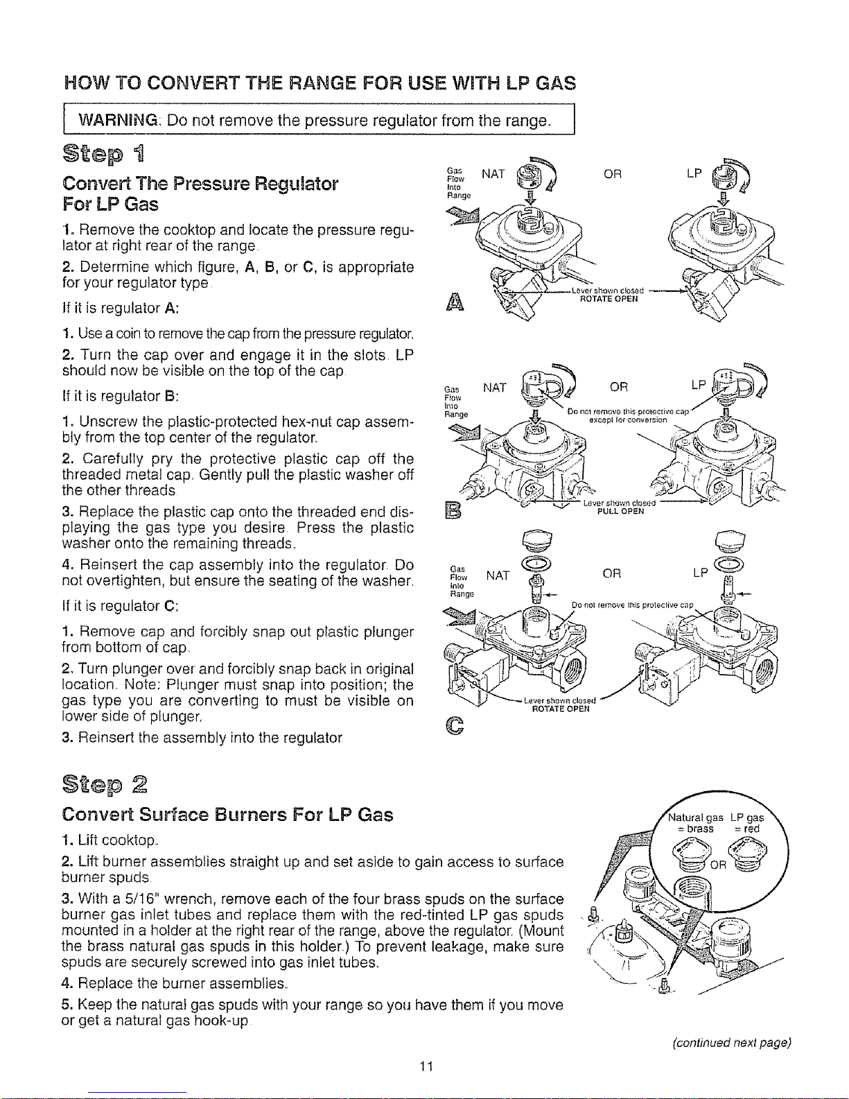
Convert The Pressure Regulator
For LP Gas
1. Remove the cooktop and locate the pressure regu-
lator at right rear of the range
2. Determine which figure, A, B, or C, is appropriate
for your regulator type
If it is regulator A:
1. Use a coin to remove the cap from the pressure regulator.
2. Turn the cap over and engage it in the slots LP
should now be visible on the top of the cap
If it is regulator B:
1. Unscrew the plastic-protected hexmut cap assem-
bly from the top center of the regulator.
2, Carefully pry the protective plastic cap off the
threaded metal cap,. Gently pull the plastic washer off
the other threads
3. Replace the plastic cap onto the threaded end dis-
playing the gas type you desire Press the plastic
washer onto the remaining threads.,
4. Reinsert the cap assembly into the regulator, Do
not overtighten, but ensure the seating of the washer,
If it is regulator C:
1. Remove cap and forcibly snap out plastic plunger
from bottom of cap.
2, Turn plunger over' and forcibly snap back in original
location,, Note: Plunger must snap into position; the
gas type you are converting to must be visible on
lower side of plunger,
3. Reinsert the assembly into the regulator
A
Ga_ NAT OR LP
,o,o . °
PULL OPEN
G_s
Plow
Inlo
Range
©
oR LP
ROTATE OPEN
2
Convert Surface Burners For LP Gas
1. Lift cooktop.,
2. Lift burner assemblies straight up and set aside to gain access to surface
burner spuds
3. With a 5/16" wrench, remove each of the four brass spuds on the surface
burner gas inlet tubes and replace them with the red-tinted LP gas spuds
mounted in a holder at the right rear of the range, above the regulator (Mount
the brass natural gas spuds in this holder.) To prevent leakage, make sure
spuds are securely screwed into gas inlet tubes,,
4. Replace the burner assemblies.,
5. Keep the naturai gas spuds with your range so you have them if you move
or get a natural gas hook-up
11
(continued next page)
staHation nst uctions (oont n0e¢
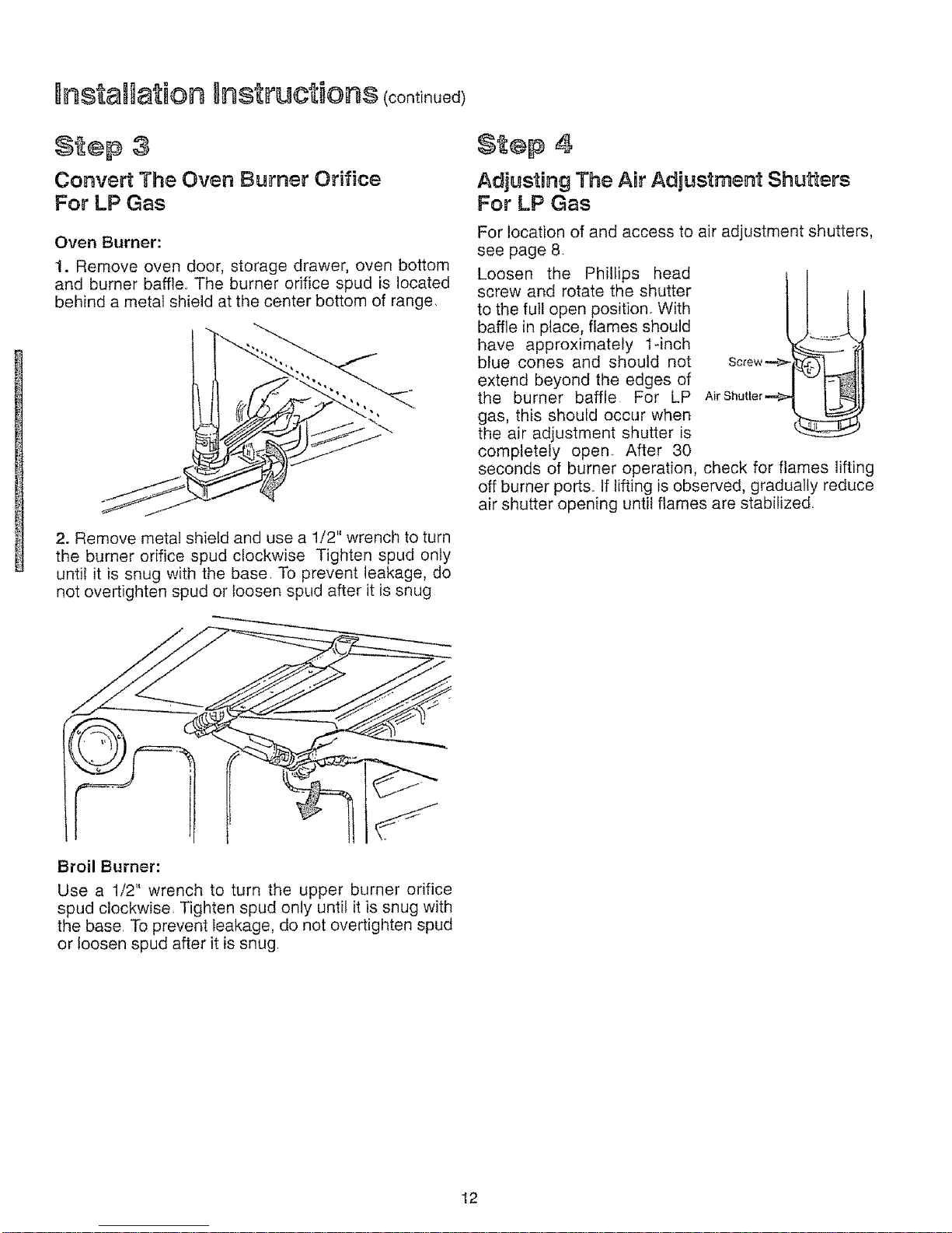
Convert The Oven Burner Orifice
For LP Gas
Oven Burner:
1. Remove oven door, storage drawer, oven bottom
and burner baffle.. The burner orifice spud is located
behind a metal shield at the center bottom of range.
2. Remove metal shield and use a 1/2" wrench to turn
the burner orifice spud clockwise Tighten spud only
until it is snug with the base To prevent leakage, do
not overtighten spud or loosen spud after it is snug
St®p 4
Adjusting The ABrAdjustment Shutters
For LP Gas
For location of and access to air adjustment shutters,
see page 8.
Loosen the Phillips head
screw and rotate the shutter
to the full open position. With
baffle in place, flames should
have approximately 1-inch
blue cones and should not
extend beyond the edges of
the burner baffle For LP
gas, this should occur when
the air adjustment shutter is
completely open After 30
seconds of burner operation, check for flames lifting
off burner ports. If lifting is observed, gradually reduce
air shutter opening untit flames are stabifized.
Broil Burner:
Use a 1/2" wrench to turn the upper burner orifice
spud clockwise Tighten spud only until it is snug with
the base To prevent leakage, do not overtighten spud
or loosen spud after it is snug
12
 Loading...