

Kenmore 72180012400 Installation Guide
upper cabinettemp!ate o
o
I
!
I
Part No. 4922W1AO21E
_1111
o
III1_
o"
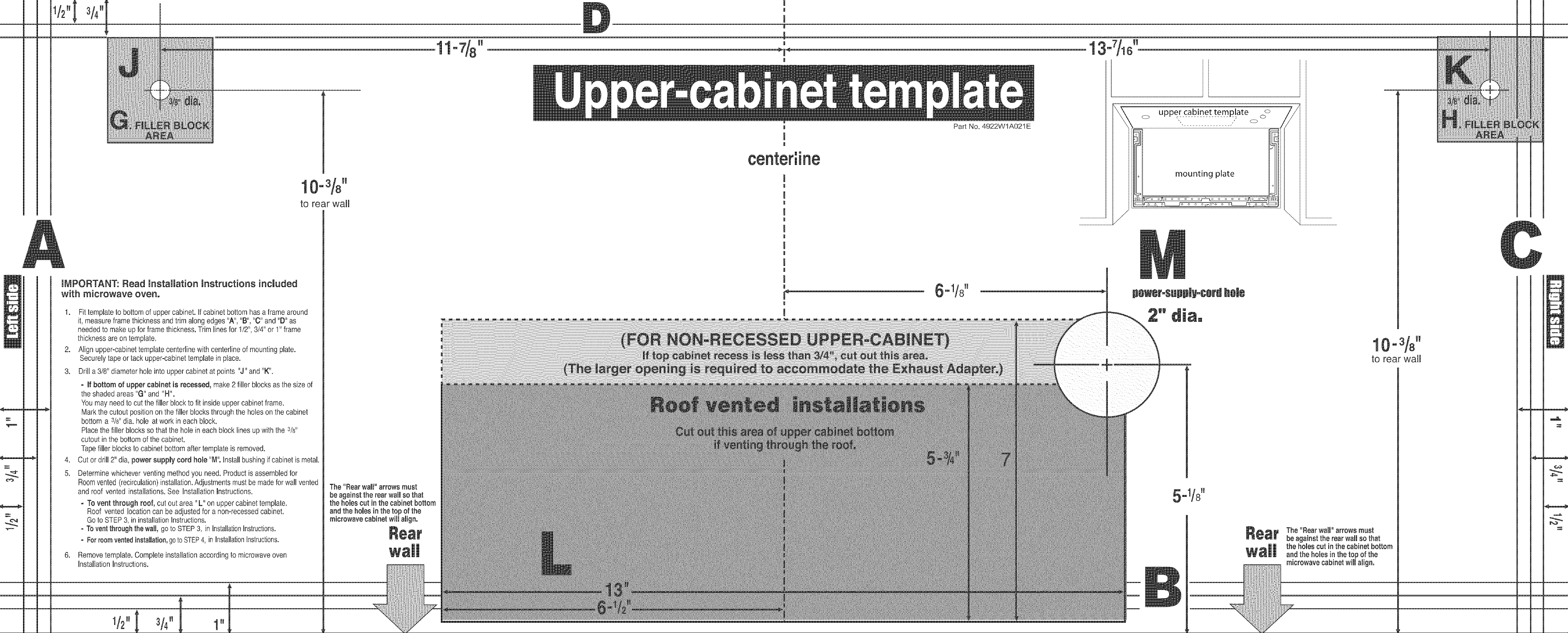
UMPORTANT: Read UnstaUmation[nstructions incmuded
with microwave oven.
.
Fit template to bottom of upper cabinet. If cabinet bottom has aframe around
it, measure frame thickness and trim along edges "A", "B", "0" and "D" as
needed to make up for frame thickness. Trim lines for 112",3/4" or 1"frame
thickness areon template.
.
Align upper-cabinet template centerline with centerline of mounting plate.
Securely tape or tack upper-cabinet template inpnace.
3.
Drill a 3/8" diameter hole into upper cabinet at points "J" and "K".
- mfbottom of upper cabinet is recessed, make 2 filler Nocks as the size of
the shaded areas "G" and "H".
You may need to cut the filler Nock to fit inside upper cabinet frame.
Mark the cutout posutionon the tiller bmocksthrough tlqehoHeson the cabinet
bottom a 3t8"dia. hole at work in each block.
Place the filler blocks so that the hole in each block lines up with the 3/8"
cutout in the bottom of the cabinet.
Tapefiller blocks to cabinet bottom after template is removed.
.
Cut or drill 2" dia, power supply cord hole "M". Install bushing if cabinet is metal.
5.
Determine whichever venting method you need. Product is assembled for
Roomvented (recirculation) installation.Adjustments must be madefor wall vented
and roof vented installations. See Installation mnstructions.
- To vent through roof, cut out area "L" on upper cabinet template.
Roof vented location can be adjusted for a non-recessed cabinet.
Go to STEP3, in installation Instructions.
- Tovent through the wall, go to STEP 3, in InstallationInstructions.
- Forroomvented installation, goto STEP4, in InstallationInstructions.
.
Remove template. Complete installation according to microwave oven
Installation Instructions.
11
to rear wahl
The "Rear wall" arrows must
be against the reaJ walmso that
the holes cut in th, cabinet bottom
and the homesin fl" top of the
microwave cabinet will align.
!
I
o mounting plate
o
J
I
J
I
\
!
I
!
I
!
I
!
I
I
-,1/8H
power-$upply-cor'dhole
J
11
1 -
to rear wall
5,.1/8 ww
The "Rear walm"arrows must
be against the rear wall so that
the holes cut in the cabinet bottom
and the holes in the top of the
microwave cabinet wiJmalign.
v2"l '/,"[ 1"
1/2"[
3/4"[
o uppercab!p_ettem_P!ate oo
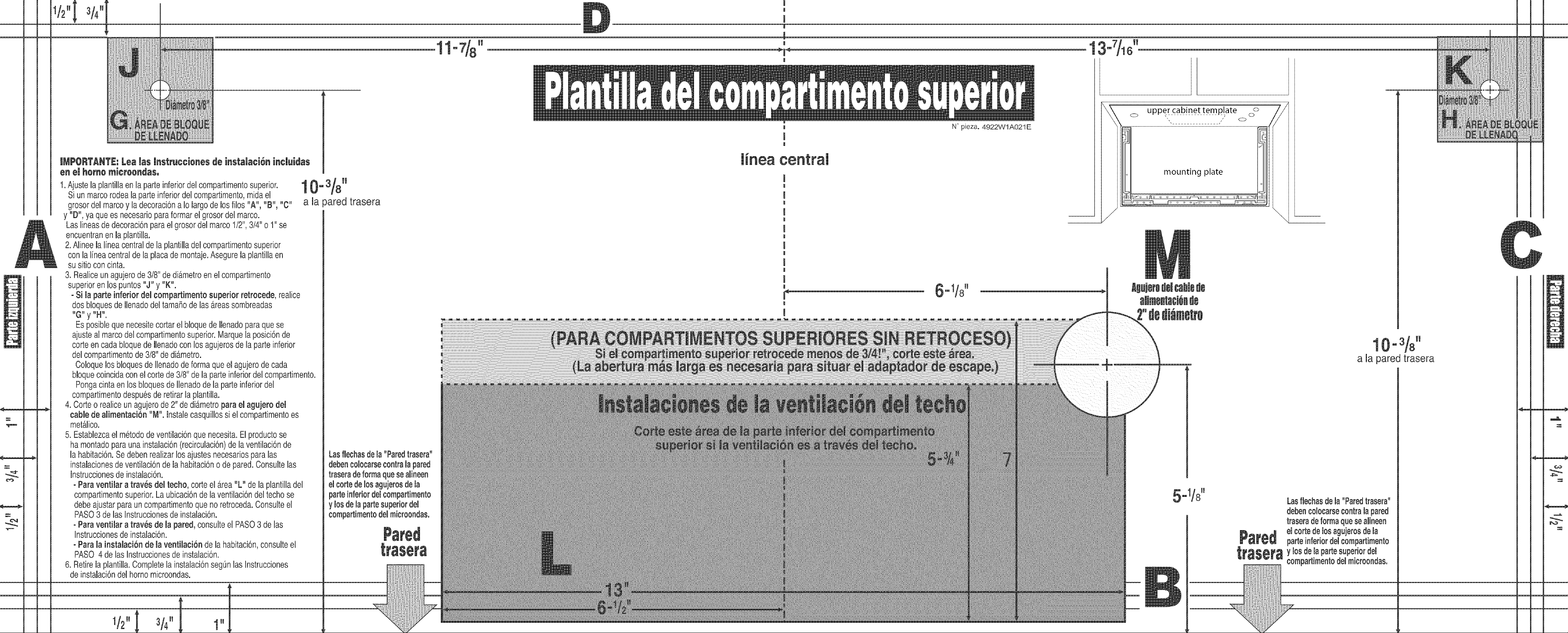
|MPORTANTE:Lealas mnstra¢cienesdeinstala¢i6n incmaiaas
eneJheinemicreenaas,
1.AjustelaphntiHaen laparteinferiordeIcompartimentosuperior.
Siunmarcorodeah parteinferiordelcompartimento,midael
grosordeImarcoy ladecoraci6naIo[argode[osfiios "A", "B", "C"
y "D", ya quees necesarioparaformarel grosordel marco.
Laslineasdedecoraci6nparael grosordelmarco1t2",3/4"o 1"se
encuentranenla phntilla.
2.Alineela lineacentralde la plantilladelcompartimentosuperior
conla I[neacentralde la placademontaje.Asegurela plantillaen
su sitioconcinta.
3. Reaiiceunagujerode 3/8"dediametroenelcompartimento
superiorenlospuntos"J" y "K".
- Si la parteinferiordei compartimento superior retrocede, realice
dosbloquesdellenadodeltamaSodelas&reassombreadas
"G" y "H".
EsposiMequenecesitecortarel NoquedeIlenadoparaquese
ajustealmarcodelcompartimentosuperior.Marquelaposici6nde
corteencadaNoquedelienadoconlosagujerosde laparteinferior
delcompartimentode3/8"dediametro.
ColoquelosNoquesdeIlenadodeformaqueel agujerodecada
bloquecoincidaconel cortede3/8"delaparteinferiordeIcompartimento.
Pongacintaenlos bioquesdeIlenadodelaparteinferiordel
compartimentodespuesderetirarla plantilia.
4. Corteo realiceunagujerode2"dedi_metroparael agu]erodel
cane deamimentaci6n"M". lnstalecasquiilossiel compartimentoes
metalico.
5. EstabiezcaeImetododeventilaci6nquenecesita.EIproductose
hamontadoparaunainstalacbn(recirculacbn)de laventilacbnde
la habitaci6n.Sedebenrealizarlosajustesnecesadosparalas
instalacionesdeventilacbndela habitacbnode pared.Consultelas
lnstruccionesde instalaci6n.
- Paraventilaratrav6s demtecho, corteel area"L" de laplantiliadel
compartimentosuperior.Laubicaci6ndelaventilacbndeltechose
debeajustarparauncompartimentoquenoretroceda.Consulteel
PASO3delas Instruccionesde instalacbn.
- Paraventilaratrav6s de mapared,consulteelPASO3de las
Instruccionesdeinstalaci6n.
- Paramainstalaci6ndemaventiiaci6ndela habitaci6n,consulteel
PASO 4delasInstruccionesde instalaci6n.
6. Retirelaplantiiia.Completelainstalaci6nseg0nlasInstrucciones
deinstalaci6ndel homomicroondas.
a la )ared trasera
11
LasflechasdeHa"Paredtrasera"
debencoiocarse( lapared
traseradeforma¢uesealineen
eltorte delosag_"erosdela
parteinferiordel(
y losdelapartes,
compartimentod_
partimento
_eriordel
microondas.
I
!
I
linea cent
!
I
!
I
!
I
!
I
!
I
!
I
!
I
I
!
N° piezao 4922W1AO21E
6" 1/8_w
mounting plate
OoOoO OoOo
Jtgujerodolcabledo
2"ded ol[ro
5,.1/8 ww
I
11
1 °
a Hapared trasera
Lasflechasdela"Paredtrasera"
debencolocarsecontraHapared
traseradeformaqueseamineen
eltorte delosagujerosdela
parteinferiordelcompartimento
y losdelapartesuperiordel
compartimentodelmicroondas.
+/2"[+/+"[ I"
 Loading...