

Kenmore 721.67903, 721.67902, 721.67909 Service Manual

삼 흥
삼 흥
정 판
정 판
MODEL 721.67902
721.67903
721.67909
DIVISION 20
BASIC FIELD MANUAL
FOR
MICROWAVE OVEN
MODEL 721.67902600
721.67903600
721.67909600
JUNE, 2006

CAUTION
WARNING TO SERVICE TECHNICIANS
PRECAUTIONS TO BE OBSERVED BEFORE
AND DURING SERVICING TO AVOID
POSSIBLE EXPOSURE TO EXCESSIVE
MICROWAVE ENERGY
a. Do not operate or allow the oven to be operated with the door open.
b. Make the following safety checks on all ovens to be serviced before activating the
magnetron or other microwave source, and make repairs as necessary; (1) Interlock
operation, (2) proper door closing, (3) seal and sealing surfaces (arcing, wear, and
other damage), (4) damage to or loosening of hinges and latches, (5) evidence of
dropping or abuse.
c. Before turning on microwave for any service test or inspection within the microwave
generating compartments, check the magnetron, wave guide or transmission line, and
cavity for proper alignment, integrity, and connections.
d. Any defective or misadjusted components in the interlock, monitor, door seal, and
microwave generation and transmission systems shall be repaired adjusted by
procedures described in this manual before the oven is released to the owner.
e. A Microwave leakage check to verify compliance with the Federal performance
standard should be performed on each oven prior to release to the owner.
• Proper operation of the microwave ovens requires that the magnetron be assembled to the wave guide and
cavity. Never operate the magnetron unless it is properly installed.
• Be sure that the magnetron gasket is properly installed around the dome of the tube whenever installing the
magnetron.
• Routine service safety procedures should be exercised at all times.
• Untrained personnel should not attempt service without a thorough review of the test procedures and safety
information contained in this manual.

CONTENTS
MODEL 721.67902
721.67903
721.67909
(Page)
SAFETY PRECAUTIONS
SPECIFICATIONS
CAUTIONS
--------------------------------------------------------------------------------------------------------------
INSTALLATIONS
-----------------------------------------------------------------------------------------------------
------------------------------------------------------------------------------------------------------
OPERATING INSTRUCTIONS
FEATURES
CONTROL PANEL
OPERATING SEQUENCE
SCHEMATIC DIAGRAM
CIRCUIT DESCRIPTION
-----------------------------------------------------------------------------------------------------------------------
SERVICE INFORMATION
TOOLS AND MEASURING INSTRUMENTS
MICROWAVE LEAKAGE TEST
MEASUREMENT OF MICROWAVE POWER OUTPUT
---------------------------------------------------------------------
------------------------------------------------------------------------------------
-------------------------------------------------------------------------------------------------------------
---------------------------------------------------------------------------------------------------
------------------------------------------------------------------------------------------------------
-----------------------------------------------------------------------------------------------------
------------------------------------------------------------------------------------------
--------------------------------------------------------------------------
--------------------------------------------------------------------------------------------
Inside front cover
1-1
2-1
3-1
4-1
4-1
4-1
4-2
4-3
4-4
5-1
5-1
5-1
-----------------------------------------------------------
5-3
DISASSEMBLY AND ADJUSTMENT
INTERLOCK CONTINUITY TEST
COMPONENT TEST PROCEDURE
TROUBLE SHOOTING
EXPLODED VIEW
-----------------------------------------------------------------------------------------------------
----------------------------------------------------------------------------------------------------
REPLACEMENT PARTS LIST
------------------------------------------------------------------------------------
-----------------------------------------------------------------------------------------
--------------------------------------------------------------------------------------
5-3
5-8
5-9
5-14
6-1
------------------------------------------------------------------------------------
7-1

SPECIFICATIONS
Rated Power Consumption
Output
Microwave
Convection
Combination
Frequency
Power Supply
Rated Current
Magnetron Cooling
Microwave Stirring
Rectification
Door Sealing
Safety Devices
Magnetron
High Voltage Capacitor
High Voltage Diode
Cavity Lamp
Tray
-----------------------------------------------------------------
Overall Dimensions
Oven Cavity Size
Effective Capacity of Oven Cavity
Accessories
------------------------------------------------------
------------------------------------------------------
----------------------------------------------------
---------------------------------------------------------
---------------------------------------------------
---------------------------------------------------
--------------------------------------------
---------------------------------------------
------------------------------------------------------
-----------------------------------------------------
--------------------------------------------------
--------------------------------------------------------
-----------------------------------------------------
----------------------------------------------
------------------------------------------------------
----------------------------------
--------------------------------------
-------------------------------------------
-------------------------------------------
-----------------------
1500W
1000W (*IEC60705 Rating standard)
Adjustable 100W through 1000W, 10 steps
1500W
1500W
2450 MHz
120 V AC, 60 Hz
13 Amp.
Forced Air Cooling
Turntable
Rectification Voltage Doubler Half-Wave
Choke Cover and Choke System
Thermostat:
Open at 90°c ± 5°c
Close at 75°c ± 5°c
Fuse(20A)
Primary Interlock Switch
Secondary Interlock Switch
Interlock Monitor Switch
2M246
Capacitor: 1.0 µF, 2.1 KV AC
350 mA, 9.0 KV
125 V, 20 W
Tempered Safety Glass
225/8"(W)x20"(H)x147/8"(D)
1
/4"(W)x151/4"(H)x107/8"(D)
15
1.5 Cu.ft.
Use and Care Manual, Glass Turntable,
Rotating Ring, Metal Rack
SWITCH CHART
PRIMARY
SWITCH MODE
CONDITIONS
DOOR OPEN
DOOR CLOSED
NOTE: Use the above switch chart with circuit diagram on page 4-4.
“•” represents the connection of the terminal of each switch.
INTERLOCK
SWITCH
COM
NO
••
1-1
SECONDARY
INTERLOCK
SWITCH
COM
NO
INTERLOCK
MONITOR
SWITCH
COM
NC
•
CAUTIONS
Unlike other appliances, the microwave oven is
high-voltage and high-current equipment.
Though it is free from danger in ordinary use,
extreme care should be taken during repair.
• DO NOT operate on a 2-wire extension cord during
repair and use.
• NEVER TOUCH any oven components or wiring during
operation.
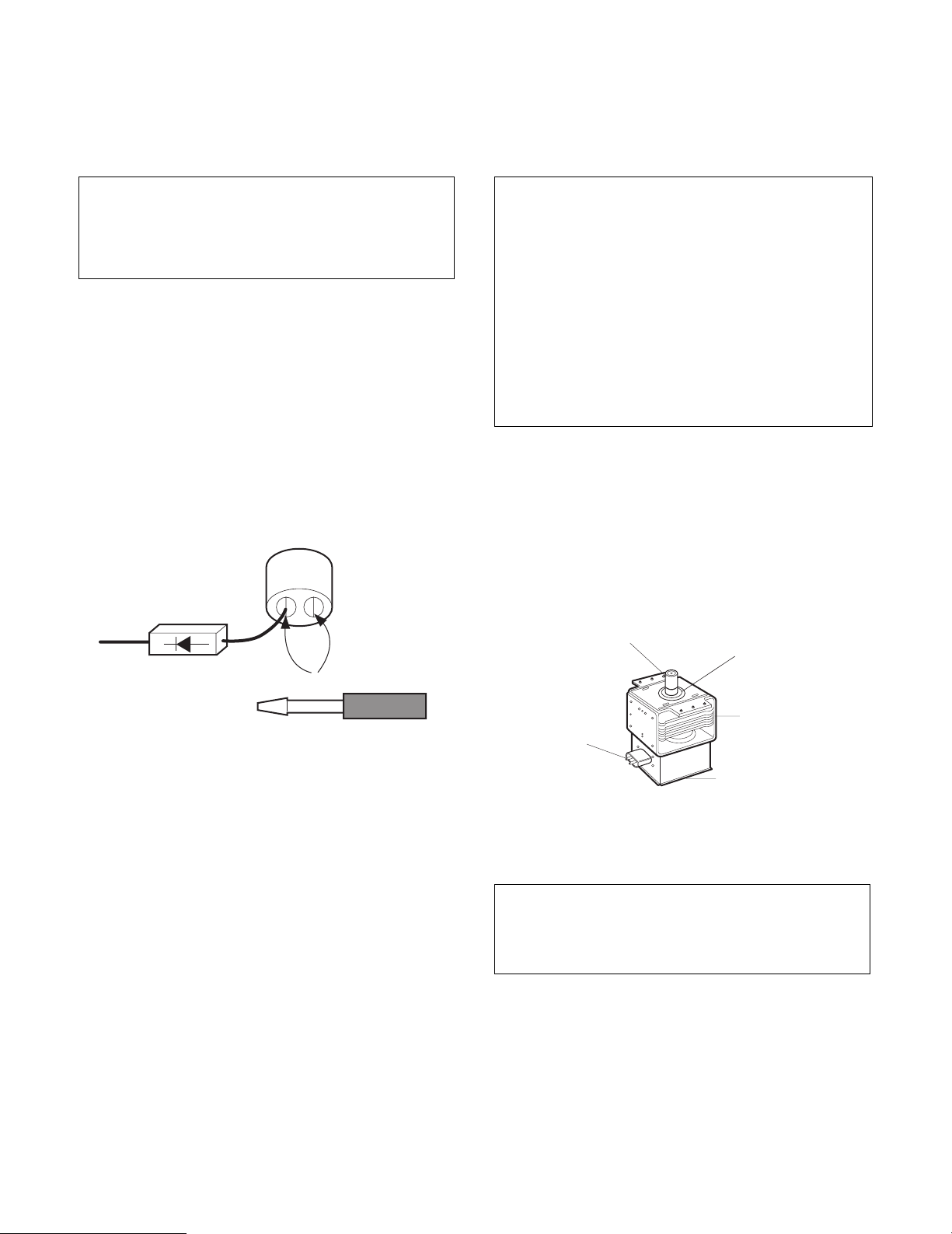
• BEFORE TOUCHING any parts of the oven, always
remove the power plug from the outlet.
• For about 30 seconds after the oven stops, an electric
charge remains in the high voltage capacitor. When
replacing or checking, you must discharge the high
voltage capacitor by shorting across the two terminals
with an insulated screwdriver.
MICROWAVE RADIATION
Personnel should not be exposed to the
microwave energy which may radiate from the
magnetron or other microwave generating
device if it is improperly used or connected.
All input and output microwave connections,
waveguide, flange, and gasket must be
secured never operate the device without a
microwave energy absorbing load attached.
Never look into an open waveguide or antenna
while the device is energized.
• Proper operation of the microwave oven requires that
the magnetron be assembled to the waveguide and
cavity. Never operate the magnetron unless it is
properly installed.
• Be sure that the magnetron gasket is properly
installed around the dome of the tube whenever
installing the magnetron.
ANTENNA
GASKET
• Remove your watches whenever working close to or
replacing the Magnetron.
• DO NOT touch any parts of the control panel circuit. A
resulting static electric discharge may damage this
P.C.B.
• NEVER operate the oven with no load.
• NEVER injure the door seal and front plate of the oven
cavity.
• NEVER put iron tools on the magnetron.
• NEVER put anything into the latch hole and the
interlock switches area.
COOLING FIN
FILAMENT
TERMINALS
MAGNETRON
CHASSIS GROUND
MAGNETRON
THE OVEN IS TO BE SERVICED ONLY
BY PROPERLY QUALIFIED SERVICE
TECHNICIANS.
2-1
INSTALLATIONS
BEFORE YOU BEGIN, READ THE FOLLOWING INSTRUCTIONS COMPLETELY AND CAREFULLY.
INSTALLING
1. Empty the microwave oven and clean inside it with
a soft, damp cloth. Check for damage such as
misaligned door, damage around the door, dents
inside the cavity, or on the exterior.
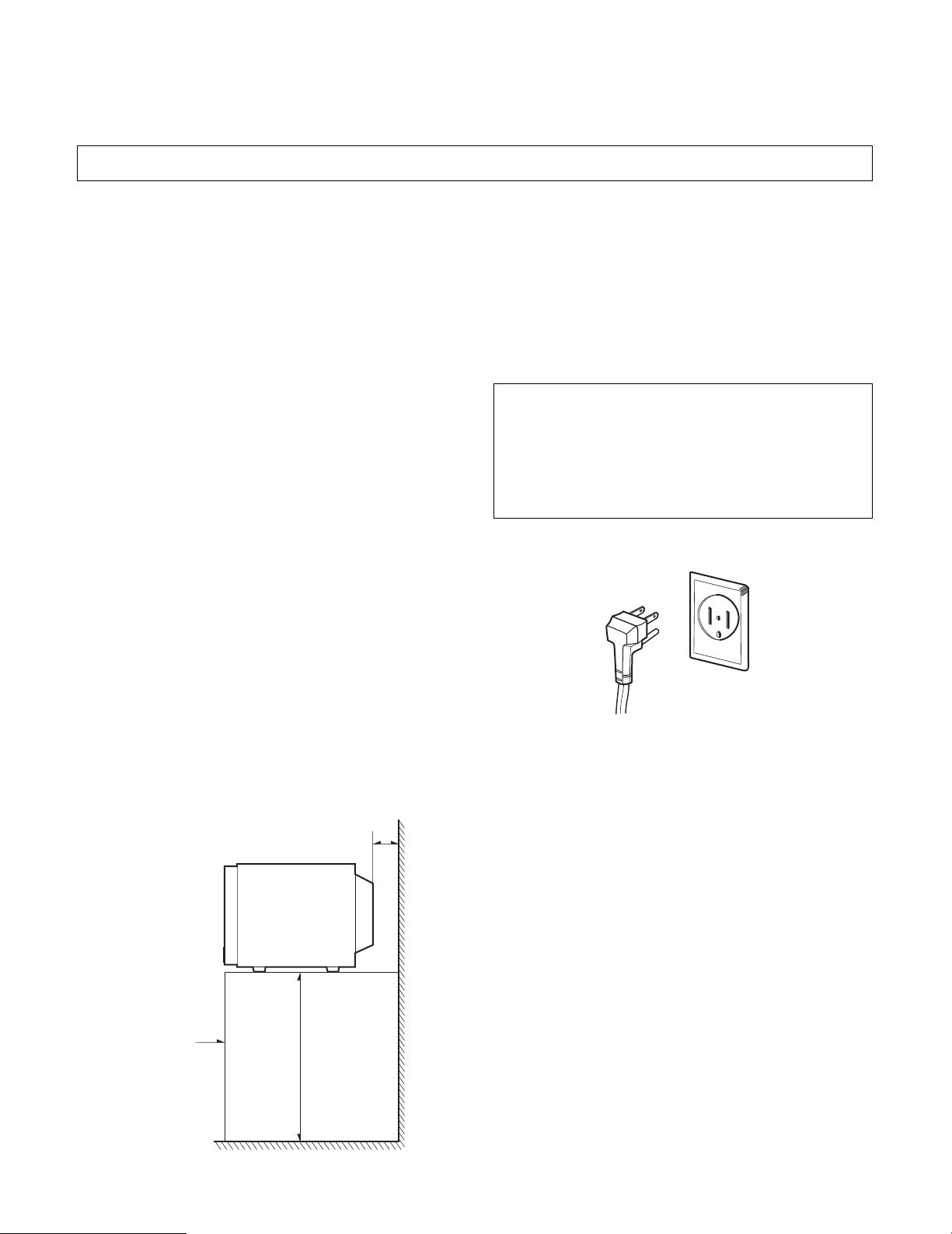
2. Put the oven on a counter, table, or shelf at least
39.4 inches(100cm) from floor that is strong enough
to hold the oven and the food and utensils you put
in it. (The control panel side of the oven is the
heavy side. Use care when handling.)
3. Do not block the vent and the air intake openings.
Blocking vent or air intake openings can cause
damage to the oven and poor cooking results.
Make sure the microwave oven legs are in place to
ensure proper air flow.
4. The oven should not be installed in any area where
heat and steam are generated, because they may
damage the electronic or mechanical parts of the unit.
Do not install the oven next to a conventional
surface unit or above a conventional wall oven.
5. Use microwave oven in an ambient temperature
less than 104°F(40°C).
6. Place the microwave oven on a sturdy and flat
surface at least 2 inches(5 cm) from the wall.
GROUNDING INSTRUCTIONS
For personal safety, this appliance must be fully
grounded at all times.
In the event of an electrical short circuit, grounding
reduces the risk of electrical shock.
The plug must be plugged into an outlet that is
properly installed and grounded.
WARNING
Improper use of the grounding plug can result in a
risk of electric shock.
Do not, under any circumstances, cut or remove
the third ground prong from the power cord plug.
PREFERRED METHOD
ENSURE PROPER GROUND
EXISTS BEFORE USE
7. Place the microwave oven as far away as possible
from TV, RADIO, COMPUTER, TELEPHONE, etc.,
to prevent interference.
5cm
Counter,
100cm
table, shelf
3-1
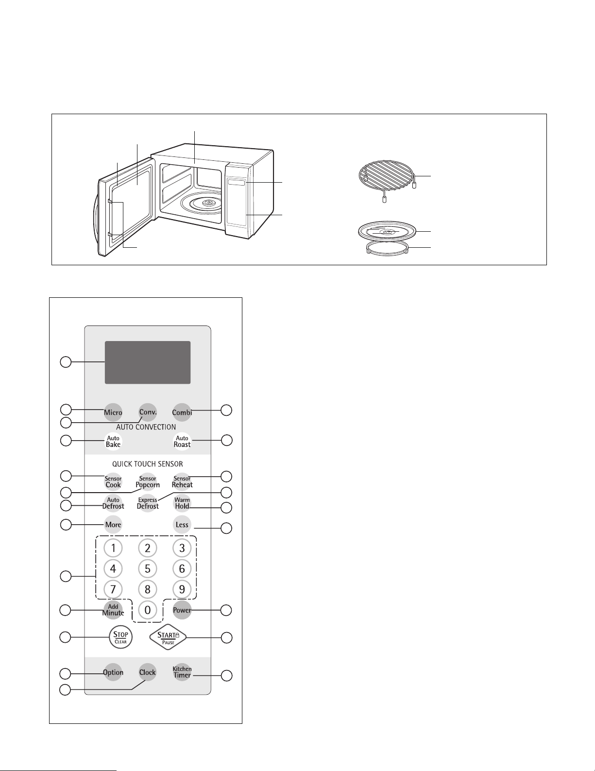
FEATURES
Metal Rack
Oven Front Plate
Window Door Screen
Door Seal
Safety Interlock
System
Control Panel
Display Window
Glass Tray
Rotating Ring
CONTROL PANEL
1
2
3
5
7
8
10
13
15
16
18
20
21
OPERATING INSTRUCTIONS
1. DISPLAY. The Display includes a clock and indicators to tell you time of day,
cooking time settings and cooking functions selected.
2. MICRO. Touch this pad when setting microwave cooking.
3. CONV. Touch this pad to operate the oven for convection cooking only.
4. COMBI. Touch this pad to program the amount roasting time and heat for a
cooking cycle using both microwave energy and convection energy.
5. CONVECTION AUTO BAKE. Touch this pad to automatically bake frozen pizza,
muffins, biscuits and frozen French fries using both microwave and convection
energy alternately.
6. CONVECTION AUTO ROAST. Touch this pad to automatically roast beef, chicken,
4
6
9
11
12
14
17
19
22
turkey breasts and pork using both microwave and convection energy alternately.
7. SENSOR COOK. Touch this pad to cook 10 types of foods. The oven's sensor
will tell the oven how long to cook depending on the amount of humidity coming
from the food.
8. SENSOR POPCORN. Touch this pad when popping commercially packaged
popcorn in your microwave oven. The oven's sensor will tell the oven how long to
cook depending on the amount of humidity it detects from the popcorn.
9. SENSOR REHEAT. Touch this pad to reheat precooked, room-temperature or
refrigerated foods. The oven's sensor will tell the oven how long to cook
depending on the amount of humidity coming from the food.
10. AUTO DEFROST. Touch this pad once to automatically defrost Meat, Poultry,
Fish or Bread according to weight. Touch this pad twice to defrost most other
frozen foods by time.
11. EXPRESS DEFROST. Touch this pad for rapid defrosting of one pound of
frozen food.
12. WARM HOLD. Touch this pad to keep hot, cooked foods warm in your
microwave oven.
13. MORE. Touch this pad to add 10 seconds of cooking time each time it is pressed.
14. LESS. Touch this pad to subtract ten seconds of cooking time each time it is
pressed.
15. NUMBER. Touch number pads to enter cooking times, cook powers, quantities,
weights, or food categories.
16. ADD MINUTE. Touch this pad to set and start cooking at 100% power.
17. POWER. Touch this pad to select a cooking power level.
18. STOP/CLEAR. Touch this pad to cancel a currently running program or erase a
cooking cycle being programmed.
19. START/PAUSE. Touch this pad to start a program or to pause the oven during
cooking or defrosting.
20. OPTION. Touch this pad to change the oven's default settings for volume, clock,
scroll speed, units of weight and language.
21. CLOCK. Touch this pad to enter the time of day.
22. KITCHEN TIMER. Touch this pad to set the kitchen timer.
4-1
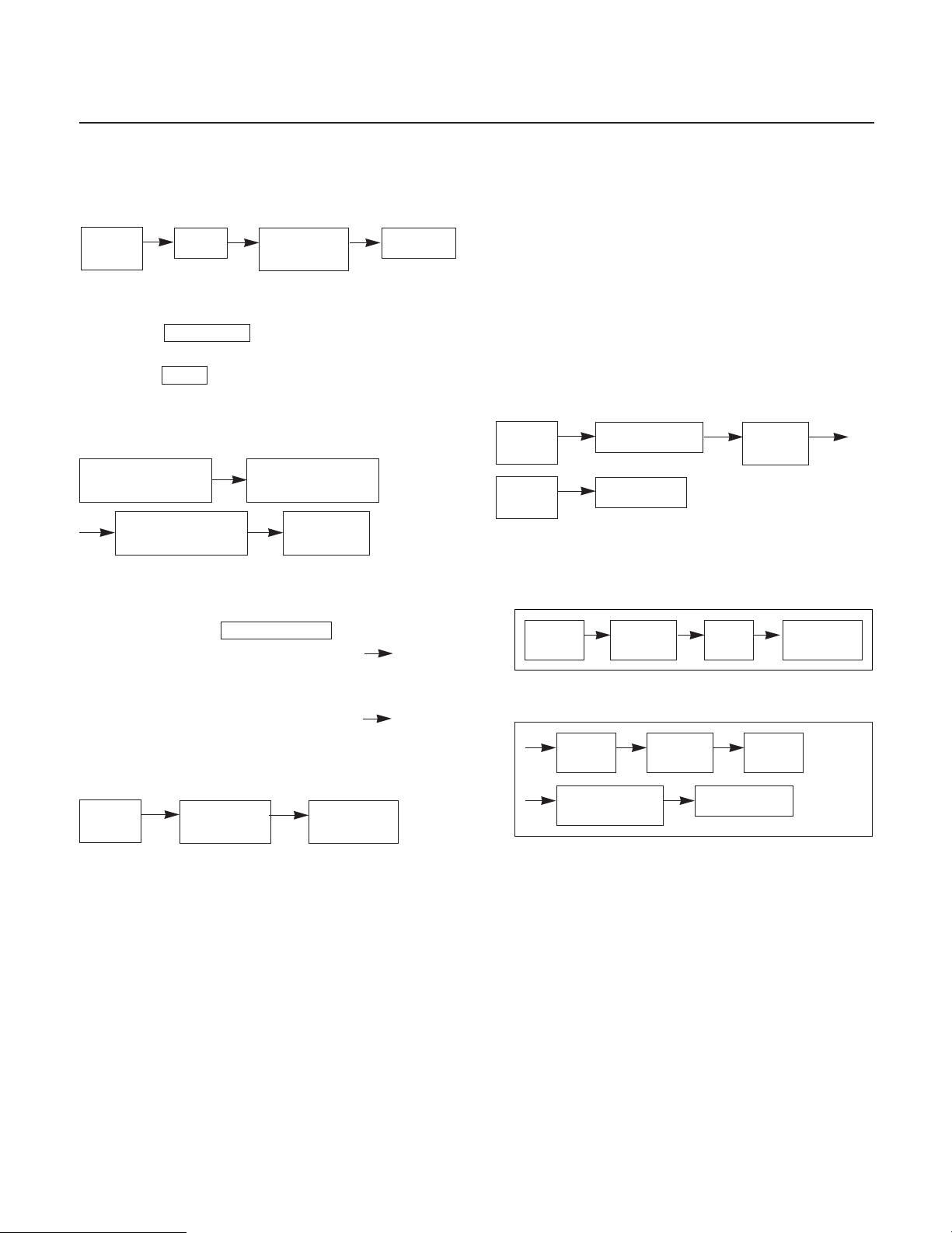
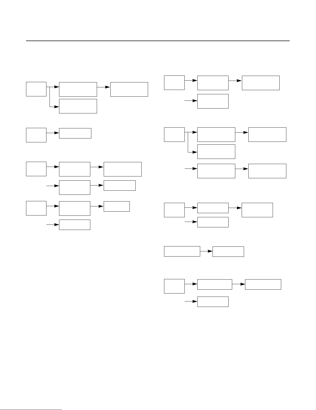
OPERATING SEQUENCE
The following is a description of component functions
during oven operation.
1. SETTING THE CLOCK
Stop/
Clear
START/PAUSE and CANCEL FUNCTION
2.
1) Touch Start/Pause pad to start oven or pause the
oven temporarily during cooking.
2) Touch Clear pad to cancel a program during
cooking or Erase during programming.
Clock
Enter time
of day
Start/Pause
3. KITCHEN TIMER.
Stop/Clear Kitchen Timer
Enter time
Start/Pause
4. CHILD LOCK
TO SET CHILD LOCK
• Touch and hold START/PAUSE pad
• Touch and hold START/PAUSE pad
LOCKED appear on the display.
TO CANCEL CHILD LOCK
• Touch and hold START/PAUSE pad
LOCKED disappear in the display.
5. WARM HOLD
Stop/
Clear
Warm Hold
Start/Pause
6. MORE / LESS
• The More and Less functions will adjust the cook
time of many oven functions.
• More/Less will add/subtract 10 seconds to the cook
time each time you press it.
NOTE:
• For convection cooking, More and Less are used as
temperature selection pads.
7. MICRO COOKING
Micro
Power
Level
Cooking time
Start/Pause
Power
8. MULTI-STAGE COOKING
1ST STAGE
Micro Power
2ND STAGE
Micro Power
Power Level
Cooking
Enter
time
Cooking
time
Start/Pause
Enter Power
Level
To keep hot, cooked food warm.
4-2
OPERATING SEQUENCE
9. SENSOR TOUCH COOKING
• Sensor cook and reheat
Stop/
Clear
• Sensor Popcorn
Stop/
Clear
Sensor Cook
Sensor Reheat
Popcorn
Select Sensor
10. AUTO DEFROST
Stop/
Clear
Stop/
Clear
Auto
Defrost
Enter the
Weight
Auto
Defrost
Select Food
category
Start/Pause
Number
menu
11. EXPRESS DEFROST
Stop/
Clear
Express
Defrost
Start/Pause
12. AUTO BAKE/ROAST
Stop/
Clear
Auto Bake
Auto Roast
Enter the
Weight
13. CONVECTION
TO PREHEAT
Stop/
Clear
Convection
Select Food
Category
Food Category
Start/Pause
Select
Temperature
Start/Pause
Start/Pause
TO COOK(After preheating)
Cooking Time
Start/Pause
14. COMBINATION
Stop/
Clear
Combi
Start/Pause
Cooking Time
4-3
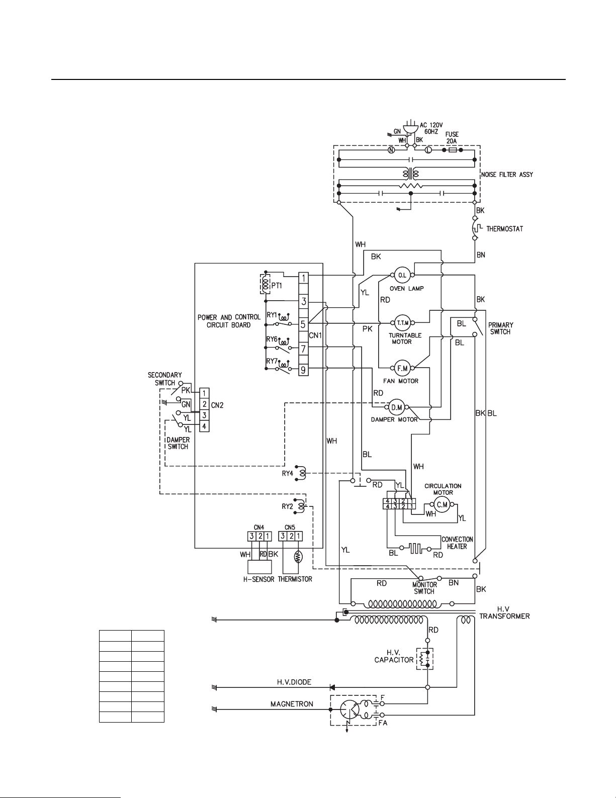
SCHEMATIC DIAGRAM
NOTE:
1. DOOR IS OPENED.
2. WIRE COLOR.
BN
WH
BK
BL
YL
PK
RD
GN
COLOR
BROWN
WHITE
BLACK
BLUE
YELLOW
PINK
RED
GREEN
SYMBOL
4-4
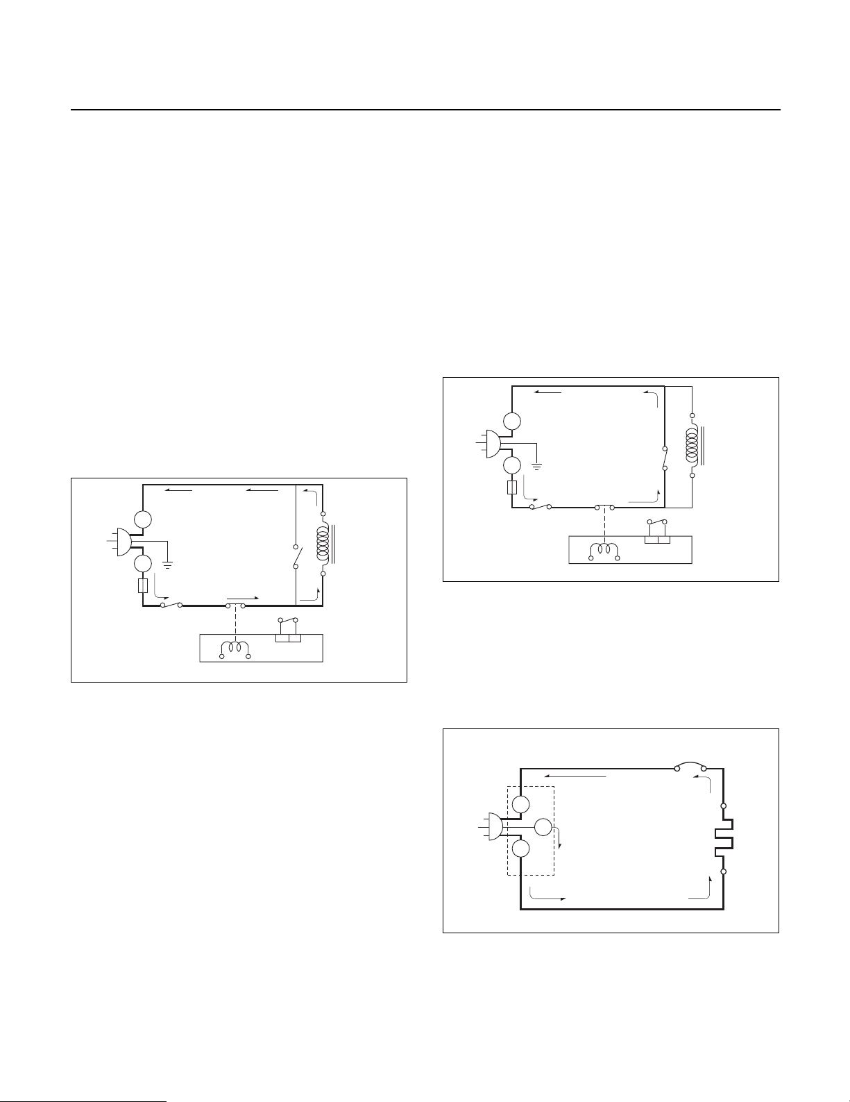
CIRCUIT DESCRIPTION
L
FUSE
H.V.
TRANS-
FORMER
RELAY 2
MICOM CONTROLLER
SECONDARY
SWITCH
PRIMARY
SWITCH
MONITOR
SWITCH
N
L
R
GENERAL DETAILS
• The low voltage transformer supplies the necessary
voltage to the micom controller when power cord is
plugged in.
• When the door is closed, the primary switch is ON, the
secondary switch is ON, and the monitor switch opens
(contact COM and NO).
WHEN SELECTING COOKING POWER
LEVEL AND TIME
• The micom controller memorizes the function you set.
• The time you set appears in the display window.
• Each indicator light turns on to indicate that the stage
has been set.
WHEN TOUCHING THE START PAD
• The coil of the relay is energized by the micom
controller.
• Power input is supplied to the high voltage transformer
through the fuse to the primary switch and relay 2.
• Turntable rotates.
WHEN THE DOOR IS OPENED DURING
COOKING
• Both the primary switch and relay 2 cut off the primary
winding voltage of the high voltage transformer.
• ON-OFF of relay 2 is coupled electrically with opening
and closing of the secondary switch.
• When the door is opened, the secondary switch is
opened and when the door is closed, the secondary
switch is closed.
• The cooking time stops counting down.
• Relay stops functioning.
• As the door is opened, if the contact of primary switch
and relay 2 and/or secondary switch fail to open, the
fuse opens due to the large current surge caused by the
monitor switch activation, which in turn stops magnetron
oscillation.
N
H.V.
TRANS-
FORME
SECONDARY
SWITCH
FUSE
L
L
PRIMARY
SWITCH
RELAY 2
MONITOR
SWITCH
• The fan motor rotates and cools the magnetron by
blowing the air.
• The air is also directed into the oven to exhaust the
vapor in the oven through the upper plate.
• Cooking time starts counting down.
• 3.15 volts AC is generated from the filament winding of
the high voltage transformer. This 3.15 volts is applied
to the magnetron to heat the magnetron filament
through two noise-preventing choke coils.
• A high voltage of approximately 2,210 volts AC is
generated in the secondary of the high voltage
transformer which is increased by the action of the high
voltage diode and charging of the high voltage
capacitor.
• The negative 4,000 Volts DC is applied to the filament
of the magnetron.
WHEN THE OVEN IS SET AT ANY LEVEL
EXCEPT MAXIMUM.
• The micom controller controls the ON-OFF time of relay
2 by the applied signal to vary the average output power
of microwave oven as POWER LEVEL. (refer to page 1-1)
• One complete cycle of relay 2 is 22 seconds.
MICOM CONTROLLER
WHEN TOUCHING THE START KEY
WITH THE CONVECTION COOKING.
• The contacts of the primary switch and the secondary
switch close the circuit.
• Damper close.
• Turntable rotates.
• Fan Motor, Circulation Motor rotate.
RELAY 4
N
G-Y
4-5
E
L
L
CONVECTION
HEATER
SERVICE INFORMATION
TOOLS AND MEASURING INSTRUMENTS
NECESSARY TOOLS
Tools normally used for TV servicing are sufficient.
Tools needed for service are listed below.
• Diagonal pliers
• Long nose pliers
• Phillips screwdriver
• Flat blade screwdriver
• Wrench (size 2 inches(5mm))
• Nutdriver (size 2 inches(5mm))
• Adjustable wrench
• Soldering iron
• Solder
• Vinyl insulation tape
• Polishing cloth
MICROWAVE LEAKAGE TEST
CAUTIONS
• Be sure to check microwave leakage prior to
servicing the oven if the oven is operative prior to
servicing.
• The service personnel should inform the
manufacture importer, or assembler of any certified
oven unit found to have a microwave emission
level in excess of 5 mW/cm2and should repair any
unit found to have excessive emission levels at no cost
to the owner and should ascertain the cause of the
excessive leakage. The service personnel should
instruct the owner not to use the unit until the oven has
been brought into compliance.
• If the oven operates with the door open, the service
personnel should:
- Tell the user not to operate the oven.
- Contact the manufacturer.
• The service personnel should check all surface and
vent openings for microwave leakage.
• Check for microwave leakage after every servicing. The
power density of the microwave radiation leakage
emitted by the microwave oven should not exceed
5 mW/cm2. Always start measuring of an unknown field
to assure safety for operating personnel from radiation
leakage.
NECESSARY MEASURING INSTRUMENTS
• TESTER (VOLTS-DC, AC, Ohm meter)
• Microwave survey meter
- Holaday HI-1500
HI-1501
- Narda 8100
8200
• Inch scale
• 600 cups (cc) non conductive material beaker (glass or
plastic), inside diameter: approx. 31/2inches (8.5 cm)
• Cylindrical and made of borosilicate glass vessel.
max. thickness: 0.12 inches (3mm)
outside diameter: approx. 7.5 inches (190mm)
height: approx. 3.5 inches (90mm)
• Glass thermometer: 212°F (100°C) (1 deg scale)
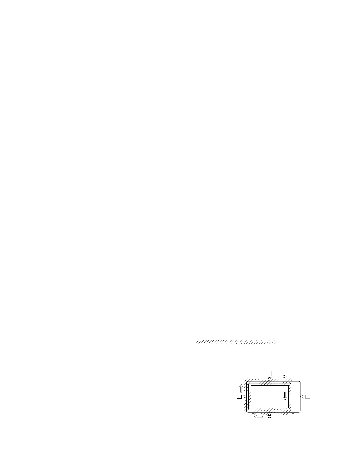
MEASURING MICROWAVE ENERGY
LEAKAGE
• Pour 275±15cc of 20±5°C(68±9°F) water in a beaker
which is graduated to 600 cc, and place the beaker
on the center of the turntable.
• Set the energy leakage monitor to 2,450 MHz and
use it following the manufacturer's recommended
test procedure to assure correct result.
• When measuring the leakage, always use the
2 inches (5cm) spacer supplied with the probe.
• Operate the oven at its maximum output.
• Measure the microwave radiation using and
electromagnetic radiation monitor by holding the
probe perpendicular to the surface being measured
Move probe along shaded area
Probe scanning speed
Less than 2.5 cm/sec
(1 in/sec)
5-1
 Loading...