

Page 1
30" ELECTRIC RANGE INSTALLATION INSTRUCTIONS
INSTALLATION AND SERVICE MUST BE PERFORMED BY A QUALIFIED INSTALLER.
IMPORTANT: SAVE FOR LOCAL ELECTRICAL INSPECTOR'S USE.
READ AND SAVE THESE INSTRUCTIONS FOR FUTURE REFERENCE.
FOR YOUR SAFETY: Do not store or use gasoline or other
United States
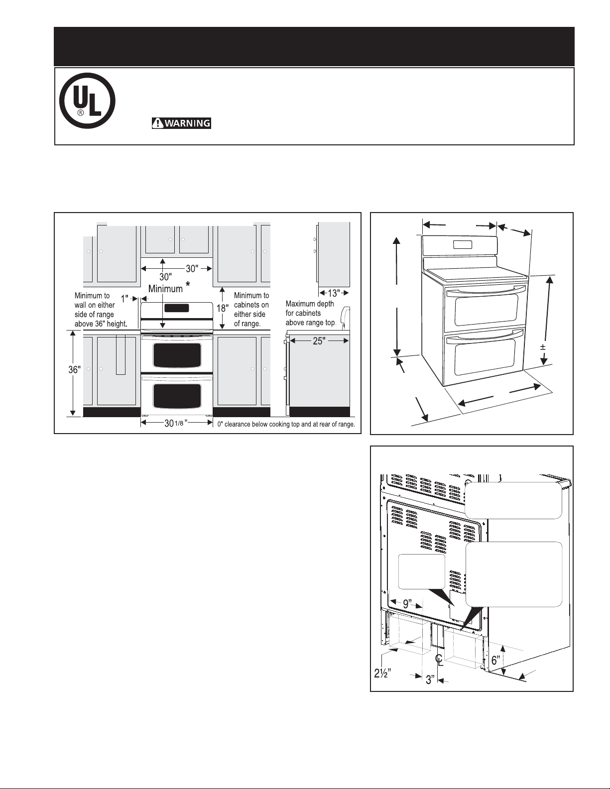
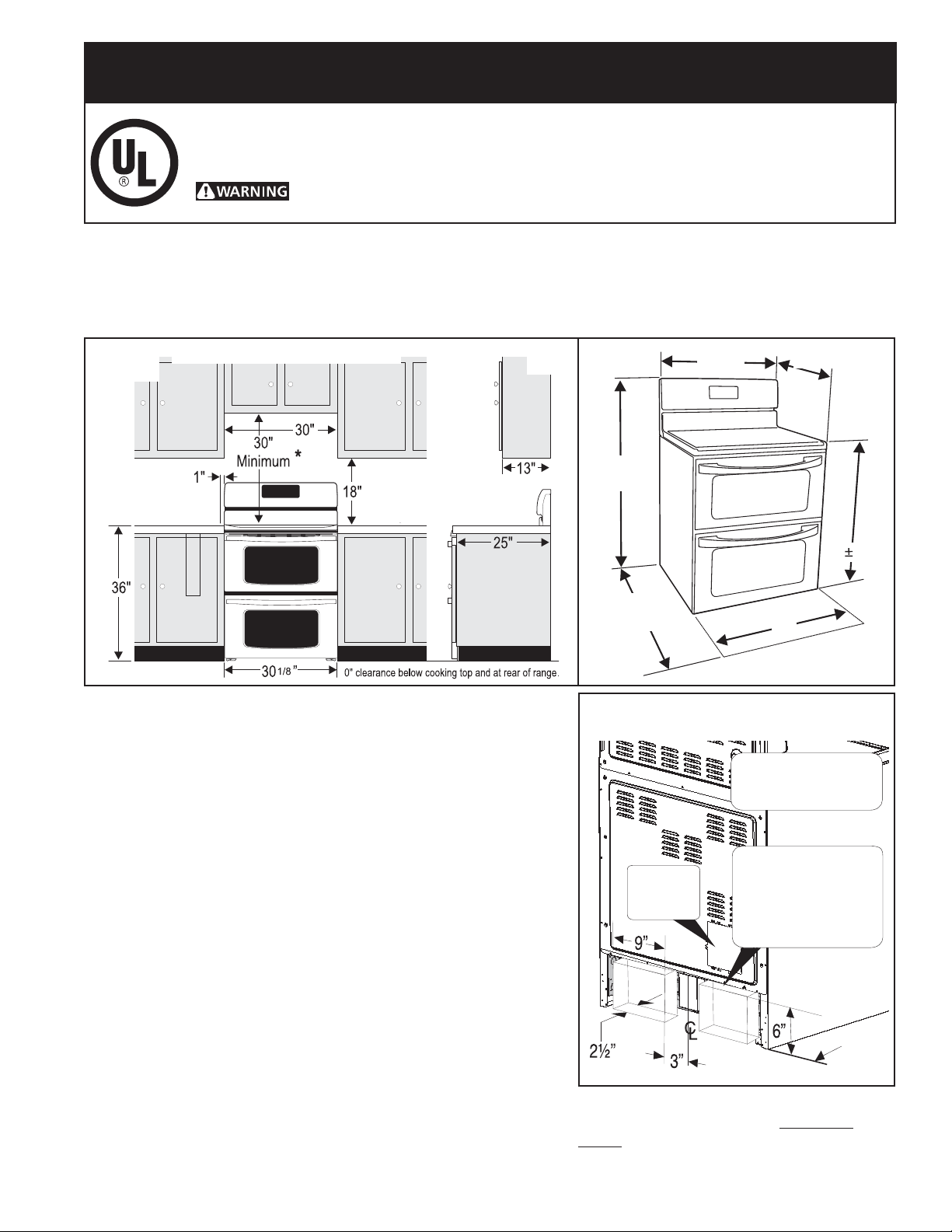
1. Clearances and Dimensions
a. Provide adequate clearances between the range and adjacent combustible surfaces.
b. Location—Check location where the range will be installed. Check for proper electrical supply and the stability of fl oor.
c. Dimensions that are shown must be used. Given dimensions provide minimum clearance. Contact surface
must be solid and level.
fl ammable vapors and liquids in the vicinity of this or any other appliance.
FRONT
VIEW
TYPICAL CABINET INSTALLATION
SIDE
VIEW
* 30" minimum clearance between the top of the cooking surface
and the bottom of an unprotected wood or metal cabinet; or 24
" minimum when bottom of wood or metal cabinet is protected
by not less than ¼" fl ame retardant millboard covered with not
less than no. 28 MSG sheet steel, 0.015" stainless steel, 0.024"
aluminum or 0.020" copper. The minimum clearance is 0" for the
rear of the range. Follow all dimension requirements provided
above to prevent property damage, potential fi re hazard, and
incorrect countertop and cabinet cuts.
Avoid locating cabinet storage space above the surface units to
eliminate the possibility of cabinets catching on fi re, or personal
burns from reaching for the cabinets over the heated units. If
cabinet storage is to be provided, risk can be reduced by installing
a range hood that projects horizontally a minimum of 5" beyond
the bottom of the cabinets.
FRONT
VIEW
49”
Maximum
42”
Door open
Terminal
Block
Location
29-7/8”
All dimensions for
electrical outlet location are
maximum.
Cubed area shows
where the electrical
outlet must be installed
for the range to be
fl ush to the wall.
25-3/4”
30”
36 1/8”
BACK
VIEW
Important Notes to the Installer
1. Read all instructions contained in these installation
instructions before installing the appliance.
2. Remove all packing material before connecting the electrical
supply to the appliance.
3. Observe all governing codes and ordinances.
4. Be sure to leave these instructions with the consumer.
Printed in Canada 318201736 (1201) Rev. A
1
Important Note to the Consumer
Keep these instructions with your Use and
Care Guide for future reference.
Wall
Edge
Page 2
30" ELECTRIC RANGE INSTALLATION INSTRUCTIONS
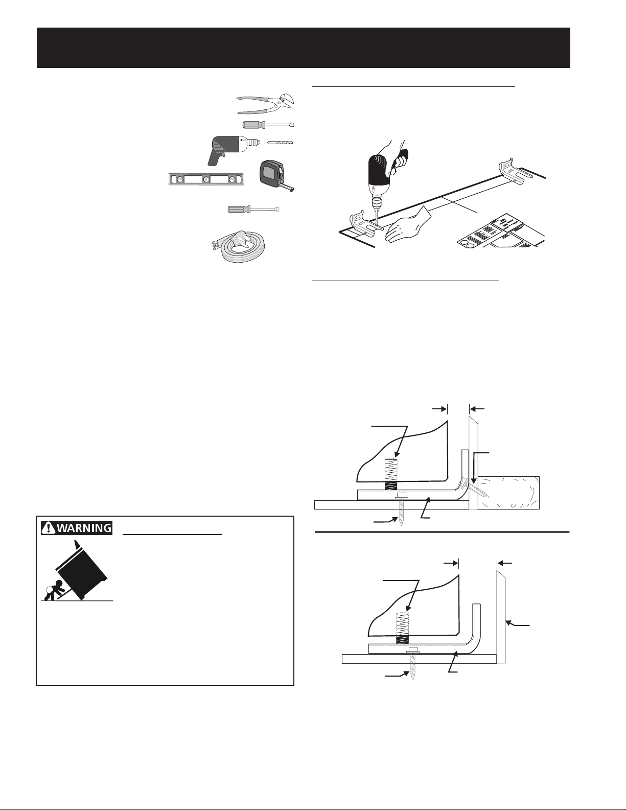
2. Tools You Will Need
For leveling legs and Anti-Tip Bracket:
• Adjustable wrench or channel lock pliers
• 5/16" Nutdriver or Flat Head Screwdriver
• Electric Drill & 1/8" Diameter
Drill Bit (Masonry Drill Bit if
installing in concrete)
• Level & Measuring Tape
For electrical supply connection:
• 1/4" & 3/8" Socket driver or Nutdriver
Additional Materials You Will Need:
• Power Supply Cord or
• Copper Electrical Wiring & Metal
Conduit (for hard wiring)
3. Anti-tip Bracket Installation Instructions
Important Safety Warning
To reduce the risk of tipping of the range, the range
must be secured to the fl oor by the properly installed
anti-tip bracket and screws packed with the range.
Failure to install the anti-tip bracket will allow the
range to tip over if excessive weight is placed on an
open door or if child climbs upon it. Serious injury
might result from spilled hot liquids or from the range
itself.
If range is ever moved to a diff erent location, the
anti-tip brackets must also be moved and installed
with the range.
Instructions are provided for installation in wood
or cement fl oor. When fastening to fl oor, be sure
that screws do not penetrate electrical wiring or
plumbing.
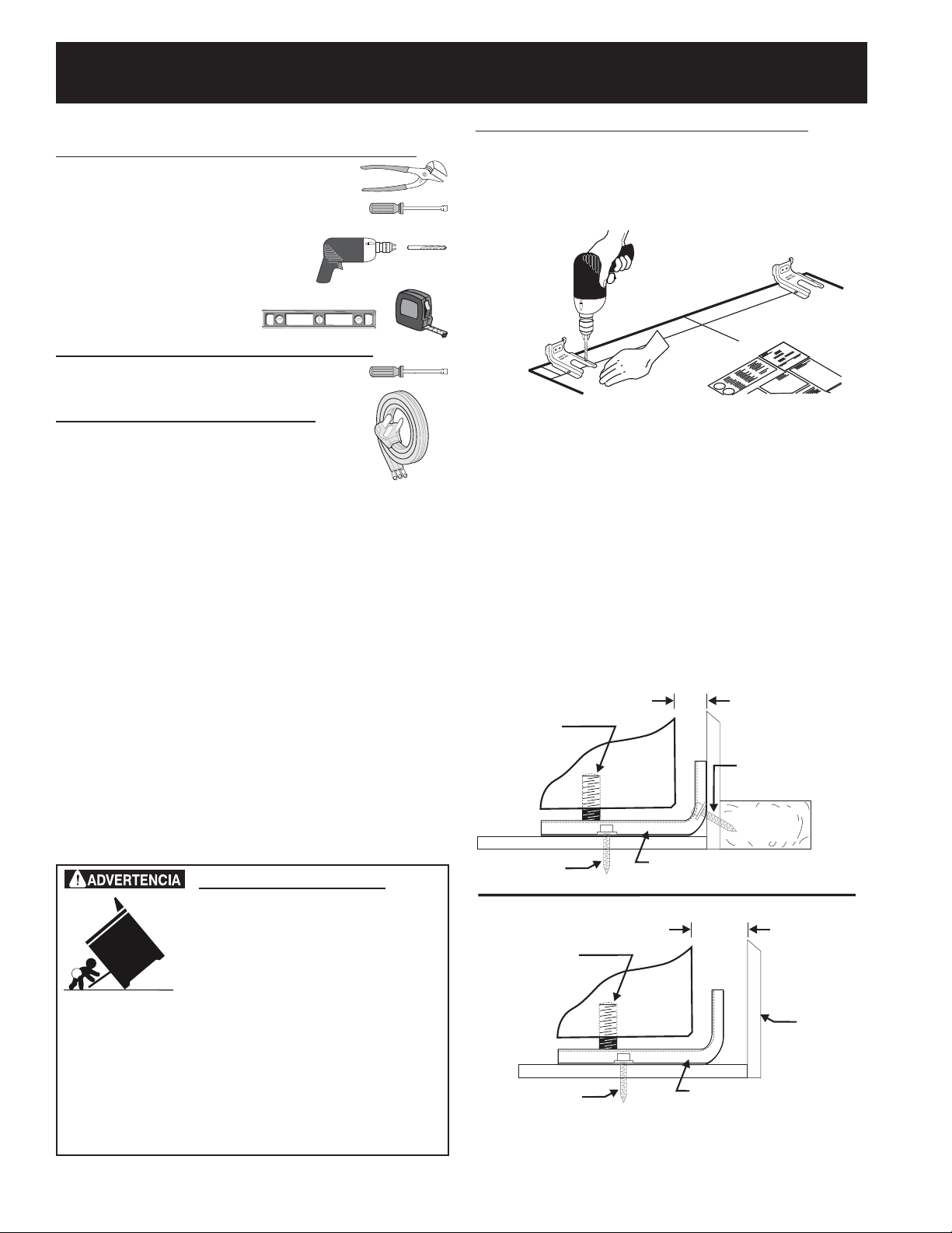
A. Locate the Bracket Using the Template - Locate
the bracket position (right or left side) by placing
the template symmetrically to the center of the fi nal
range position. Mark the location of the screw holes,
shown on template.
Figure 1
B. Drill Pilot Holes and Fasten Bracket - Drill a 1/8"
pilot hole where screws are to be located. If bracket
is to be mounted to the wall, drill pilot hole at an
approximate 20° downward angle. If bracket is to
be mounted to masonry or ceramic fl oors, drill a
3/16" pilot hole 1-3/4" deep. The screws provided
may be used in wood or concrete material. Use a
5/16" nut-driver or fl at head screwdriver to secure
the bracket in place.
FASTEN BRACKET (WALL OR FLOOR MOUNTING)
1-1/4” Max.
Leveling leg
Wall mount
Rear of Range
Wall Plate
Tip Over Hazard
A child or adult can tip the range •
and be killed.
Verify the anti-tip device has •
been installed to fl oor or wall.
Ensure the anti-tip device is re-engaged to fl oor •
or wall when the range is moved.
Do not operate the range without the anti-tip •
device in place and engaged.
Failure to follow these instructions can result in •
death or serious burns to children and adults.
Floor Mount
Anti-Tip Bracket
FASTEN BRACKET (FLOOR MOUNTING ONLY)
Leveling leg
Rear of Range
Floor Mount
Figure 2
2
Anti-Tip Bracket
More than
1-1/4”
Wall
Page 3
30" ELECTRIC RANGE INSTALLATION INSTRUCTIONS
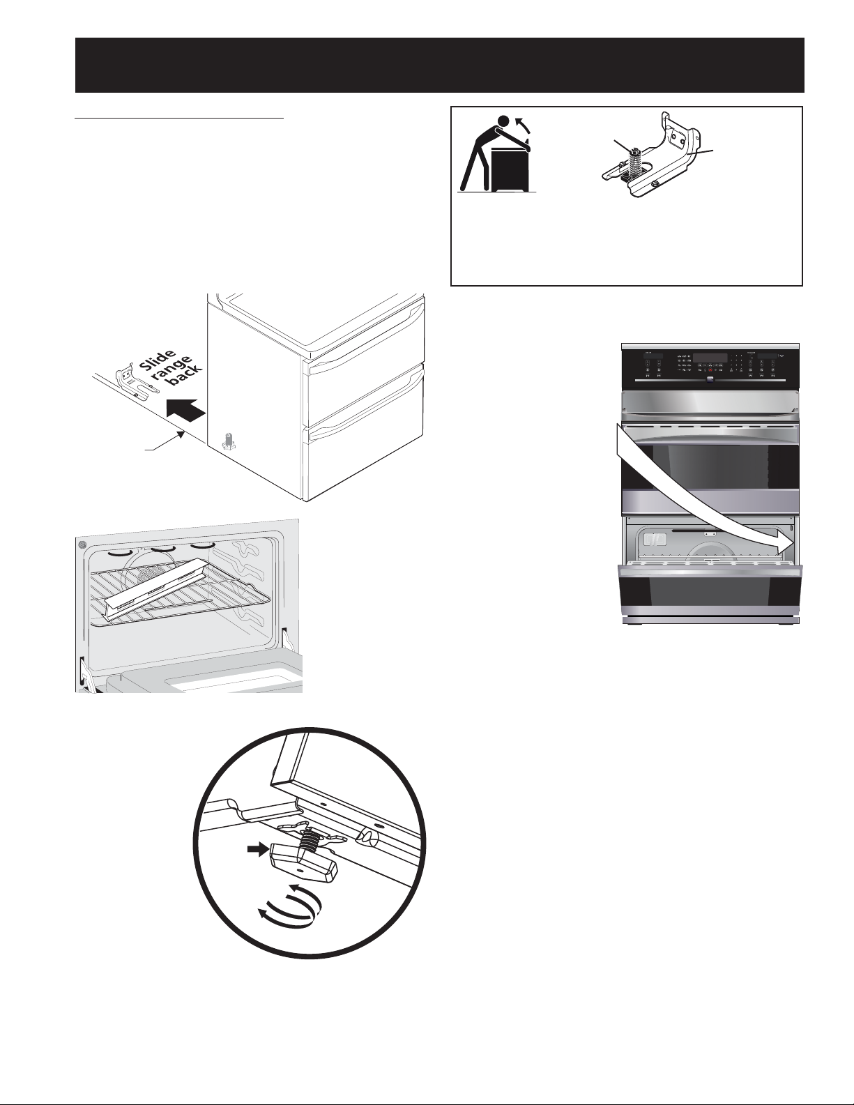
C. Level and position the range - Slide range to its
fi nal position. Insert the range leveling leg in the antitip bracket. Visually verify if the anti-tip bracket is
engaged. Lower the range by adjusting the 4 leveling
legs alternatively until the range is level. Check if the
range is level by placing a spirit level on the oven
rack. Take 2 readings with the spirit level placed
diagonally; take a reading in one direction and then
in the other direction. Level the range if necessary by
adjusting the leveling legs.
Range side
Figure 3
Range
Leveling
Leg
Anti-Tip
Bracket
To check if the anti-tip bracket is installed
properly, use both arms and grasp the rear edge
of range back. Carefully attempt to tilt range
forward. When properly installed, the range
should not tilt forward.
4. Serial Plate Information
The serial plate
is located as
shown. See the
serial plate for
the following
information:
A. Model, lot and
serial number of
range.
B. Kilowatt
rating (power
requirements).
C. Voltage ratings.
Figure 4
Leveler
Figure 6
Leg
Raise
Lower
Figure 5
3
Page 4
30" ELECTRIC RANGE INSTALLATION INSTRUCTIONS
5. Electrical Connection Requirements
This appliance must be properly installed and
grounded by a qualifi ed technician in accordance
with the National Electrical Code ANSI/NFPA
No. 70-latest edition- and local electrical code
requirements.
This appliance may be connected by means of
permanent "Hard Wiring" or "Power Supply Cord
Kit."
When hard wiring, do not leave excess wire in
range compartment. Excess wire in the range
compartment may not allow the access cover to
be replaced properly, and could create a potential
electrical hazard if wires become pinched. When
using fl exible conduit or range cable, use fl ex
connector or range cable strain relief.
NOTE: Only use copper wire in connection to
terminal block.
5.1 Models Requiring Power Supply Cord Kit
The user is responsible for connecting the power
supply cord to the connection block located behind
the back panel access cover.
This appliance may be connected by means of
permanent "hard wiring"; fl exible armored or
nonmetallic shielded copper cable (when local code
allow it) or by means of a power supply cord kit.
NOTE: Electric slide-in range is shipped from
factory with 1 1/8" (2.9 cm) dia. hole as shown on
fi gure 9. If a larger hole is required, punch out the
knockout.
Risk of fi re or electrical shock exists
if an incorrect size range cord kit is used, the
Installation Instructions are not followed, or the
strain relief bracket is discarded.
For mobile homes, new installation or recreational
vehicles, use only a power cord kit design for a
range at 125V /250V 50A recommended (minimum
40A). Cord must have either 3 (when local code
permits grounding through neutral) or 4 conductors.
Terminal on end of wires must be either closed loop
or open spade lug with upturned ends. Cord must
have strain-relief clamp. If a 50A circuit is used, a
50A power cord must be used.
Do not loosen the nuts which secure
the factory-installed range wiring to terminal
block while connecting range. Electrical failure or
loss of electrical connection may occur.
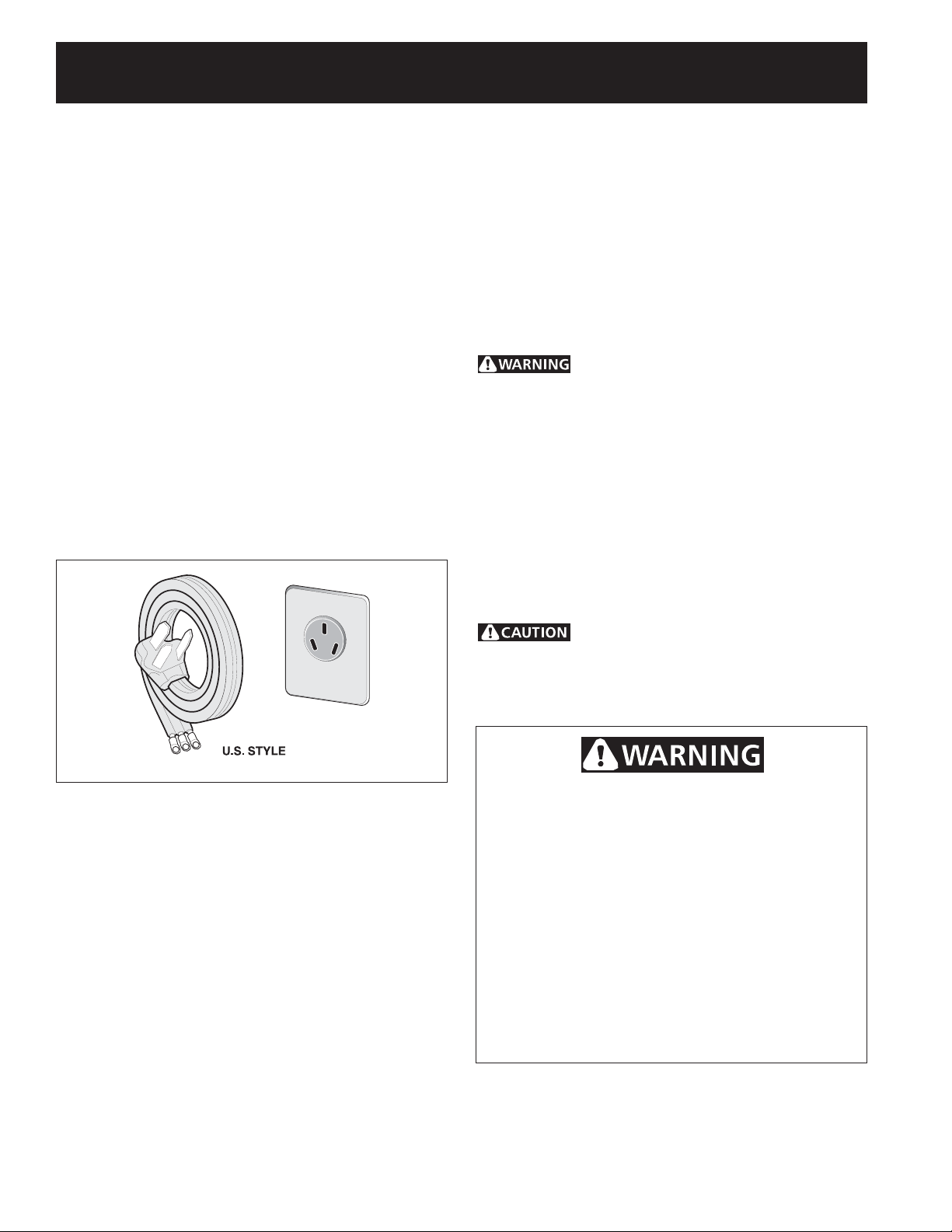
Figure 7 – 3-Wire Cord Kit
Electrical Shock Hazard
• Electrical ground is required on this appliance.
• Do not connect to the electrical supply until
appliance is permanently grounded.
• Disconnect power to the circuit breaker or fuse
box before making the electrical connection.
• This appliance must be connected to a
grounded, metallic, permanent wiring system,
or a grounding connector should be connected
to the grounding terminal or wire lead on the
appliance.
Failure to do any of the above could result in a
fi re, personal injury or electrical shock.
4
Page 5
30" ELECTRIC RANGE INSTALLATION INSTRUCTIONS
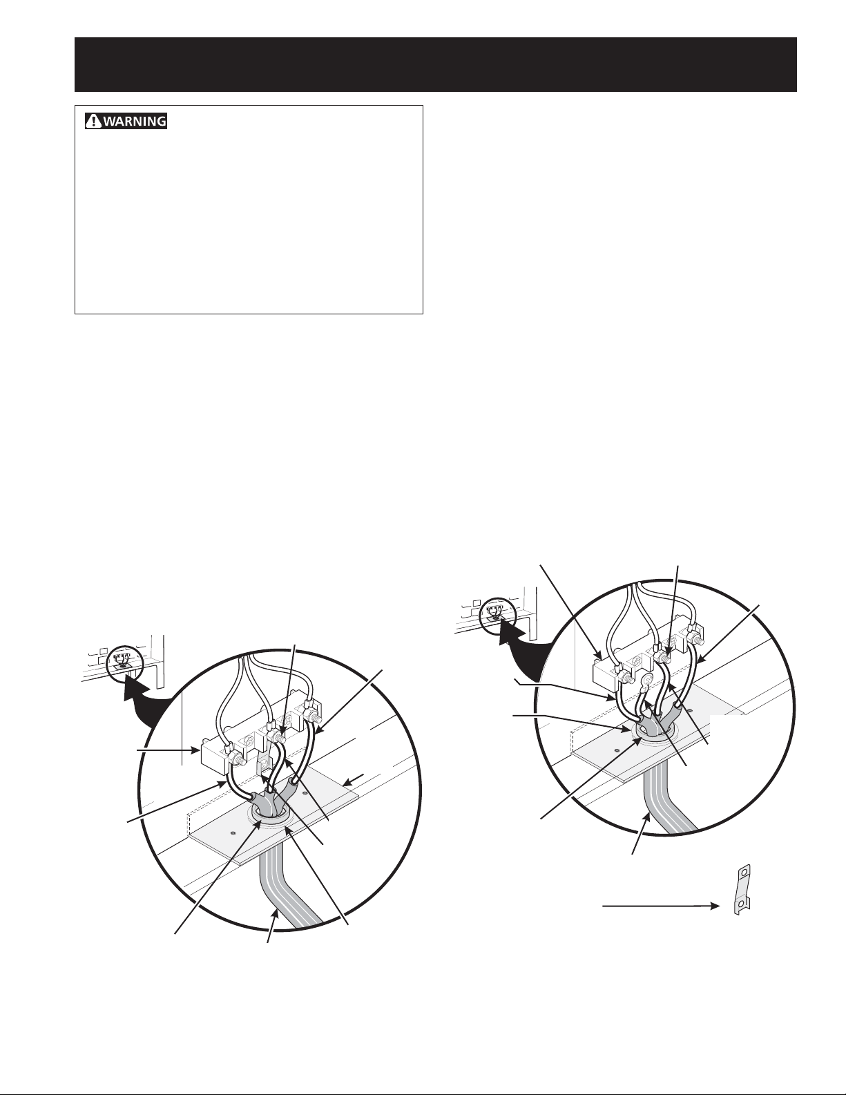
This appliance is manufactured
with the frame grounded by connection of a
grounding strap between the neutral power
supply terminal and the frame. If used in USA,
in a new branch circuit installation (1996 NEC),
mobile home or recreational vehicle, where
local code do not permit grounding through
neutral (white) wire or in Canada; remove the
grounding strap from the frame and cut the
other end, near the neutral terminal. Connect
the appliance in usual manner.
Three Conductor Wire Connection to Range
If local codes permit connection of the frame
grounding conductor to the neutral wire of the
copper power supply cord (see Figure 8):
1. Remove the screws from the access plate at
the lower right end of the rear cover to expose
range terminal connection block.
2. Using the nuts supplied in the literature
package, connect the neutral of the copper
power supply cord to the center silver-colored
terminal of the terminal block, and connect the
other wires to the outer terminals. Match wires
and terminals by color (red wires connected to
the right terminal, black wires connected to the
left terminal) (see Figure 8).
3. Replace the terminal cover and replace the
screws.
Terminal
Block
Black
Wire
Silver Colored
Terminal
Mounting
(White Wire)
Grounding
Strap
Red
Wire
Cord
Plate
Neutral
Four Conductor Wire Connection to Range
Where local codes does NOT permit connection of
the frame grounding conductor to the neutral wire
of the copper power supply cord (see Figure 9):
1. Remove the screws from the access plate at
the lower right end of the rear cover to expose
range terminal connection block.
2. Remove the grounding strap from the terminal
block and from the appliance frame.
3. Using the nuts supplied with the literature
package, connect the ground wire (green) of
the copper power supply cord to the frame of
the appliance with the ground screw, using the
hole in the frame where the ground strap was
removed (see Figure 9).
4. Connect the neutral of the copper power supply
cord to the center silver-colored terminal of
the terminal block, and connect the other
wires to the outer terminals. Match wires and
terminals by color (red wires connected to the
right terminal, black wires connected to the left
terminal).
5. Replace the terminal cover and replace the
screws.
Silver Colored
Terminal Block
Black
Wire
1 1/8" (2.9cm)
Dia. Direct
Connection
Hole. Punch Out
Knockout for
1 3/8" (3.5cm)
Dia. Cord Kit
Hole.
A User Supplied
Strain-relief Must
Be Installed at This
Location
To 240 V
Receptacle
Terminal
Red
Wire
Neutral
(White
Wire)
Ground (Bare
Copper Wire)
A User Supplied
Strain-relief Must
Be Installed at This
Location.
To 240 V
Receptacle
Figure 8
1 1/8" (2.9 cm)
Dia. Direct
Connection Hole.
Punch Out Knockout
for 1 3/8" (3.5 cm)
Dia. Cord Kit Hole.
NOTE: Be sure to remove
the supplied grounding strap.
Figure 9
5
Page 6
30" ELECTRIC RANGE INSTALLATION INSTRUCTIONS
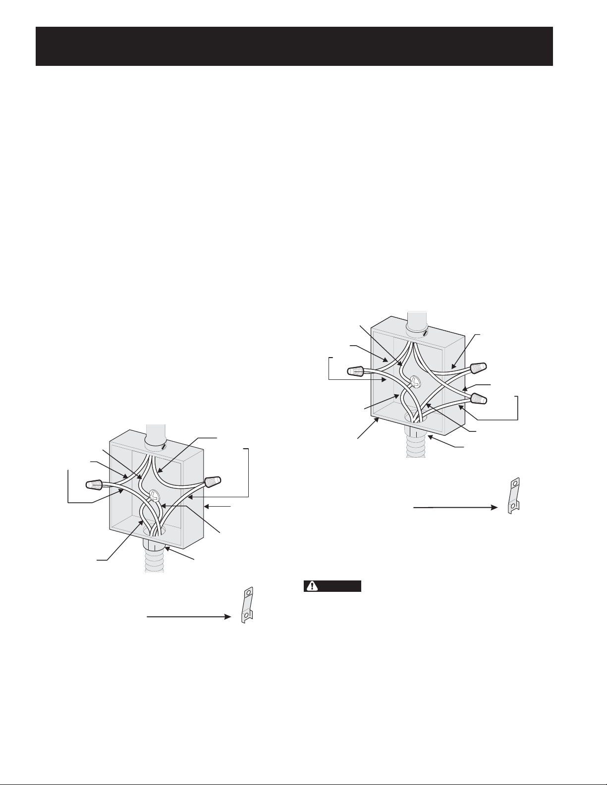
Direct Electrical Connection to the Circuit
Breaker, Fuse Box or Junction Box
If the appliance is connected directly to the circuit
breaker, fuse box or junction box, use fl exible,
armored or nonmetallic sheathed copper cable
(with grounding wire). Supply a U.L. listed strainrelief at each end of the cable. At the appliance
end, the cable goes through the Direct Connection
Hole (see Figure 9) on the Cord Mounting Plate.
Wire sizes (copper wire only) and connections
must conform to the rating of the appliance.
Where local codes permit connecting the
appliance-grounding conductor to the neutral
(white) wire (see Figure 10):
1. Be sure that no power is supplied on the cable
from residence.
2. Follow instructions on previous page for Four
Conductor Wire Connection to Range (Fig. 9).
3. In the circuit breaker, fuse box or junction box
(Fig. 10):
a) Connect the green (or bare copper) wire,
the white appliance cable wire, and the neutral
(white) wire together.
b) Connect the 2 black wires together.
c) Connect the 2 red wires together.
Cable from Residence
Neutral
(white) Wire
Red
Wires
Black
Wires
Where local codes DO NOT permit connecting
the appliance-grounding conductor to the neutral
(white) wire, or if connecting to 4-wire electrical
system (see Figure 11):
1. Be sure that no power is supplied on the cable
from residence.
2. Follow instructions on previous page for Four
Conductor Wire Connection to Range (Fig. 9).
3. In the circuit breaker, fuse box or junction box
(Fig. 11):
a) Connect the white appliance cable wire to the
neutral (white) wire.
b) Connect the 2 black wires together.
c) Connect the 2 red wires together.
d) Connect the green (or bare copper) grounding
wire to the grounding wire of the circuit
breaker, fuse box or junction box.
Cable from
Green (or Bare
Copper) Wire
Red
Wires
Green (or Bare
Copper) Wire
Junction
Box
Residence
Cable from
Appliance
White
Wire
Black
Wires
White Wire
U.L.-listed Conduit
Connector (or CSA
listed)
Junction
Green
(or Bare
Copper) Wire
Cable from
Appliance
NOTE: Be sure to remove
the supplied grounding strap.
White Wire
U.L.-listed Conduit
Connector (or CSA
listed)
Figure 10
3-Wire (Grounded Neutral) Electrical System
(Example: Junction Box)
Box
NOTE: Be sure to remove the
supplied grounding strap.
Figure 11
4-Wire Electrical System (Example: Junction Box)
6. Checking Operation
Refer to the Use and Care Guide for operation.
CAUTION
Do not touch cooktop glass or
elements. They may be hot enough to burn you.
Before You Call for Service
Read the Before You Call for Service Checklist
and operating instructions in your Use and Care
Guide. It may save you time and expense. The
list includes common occurrences that are not the
result of defective workmanship or materials in this
appliance.
Refer to your Use and Care Guide for Sears service
phone numbers, or call 1-800-4-MY-HOME
6
®
.
Page 7
INSTRUCCIONES PARA INSTALACIÓN DE LA ESTUFA ELÉCTRICA DE 30”
LA INSTALACIÓN Y EL SERVICIO DEBEN SER EFECTUADOS POR UN INSTALADOR
CALIFICADO. IMPORTANTE: GUARDE ESTAS INSTRUCCIONES PARA USO DEL
INSPECTOR LOCAL DE ELECTRICIDAD. LEA Y GUARDE ESTAS INSTRUCCIONES
PARA REFERENCIA FUTURA.
PARA SU SEGURIDAD: No almacene ni utilice gasolina u otros vapores y
Estados Unidos
líquidos infl amables en la proximidad de este o de cualquier otro artefacto.
1. Espacios y dimensiones:
a. Proporcione espacios adecuados entre la estufa y las superfi cies combustibles adyacentes.
b. Ubicación—Examine el lugar en el cual va a ser instalada la estufa. Determine la existencia de suministro eléctrico
adecuado y la estabilidad del piso.
c. Se deben usar las medidas indicadas. Las dimensiones indicadas proporcionan espacio mínimo. La superfi cie de contacto
debe ser sólida y estar a nivel.
VISTA
FRONTAL
TYPICAL CABINET INSTALLATION
VISTA
LADO
VISTA
FRONTAL
29-7/8”
25-3/4”
Mínimo a la pared a
cada lado de la
cocina o la cocina a
36” de alto.
Mínimo a los
gabinetes
sobre cada
lado de la
estufa.
Máxima distancia
entre los gabinetes y
la parte superior de
la cocina.
* Un mínimo de 30” de espacio entre la parte superior de la superfi cie
para estufa y el fondo no protegido de un gabinete de metal o
madera; o un mínimo de 24” cuando el fondo de metal o madera
del gabinete esta protegido por no menos de ¼” de material
retardante, con una hoja de acero de no menos MSG No.28, 0.015”
de acero inoxidable, 0.024” de aluminio o 0.020” de cobre. 0” es
el espacio mínimo para la parte trasera de la estufa. Siga todos los
requerimientos de medidas antes proporcionados para evitar daños a
la propiedad: peligro de incendios potenciales o superfi cies y cortes
de gabinetes que sean incorrectos.
Para eliminar el riesgo de quemaduras o incendio cuando trate
de alcanzar objetos por sobre unidades de superfi cie calentadas,
debe evitarse que los gabinetes para almacenamiento estén
localizados encima de la superfi cie de la estufa. Si existen gabinetes
de almacenamiento, el riesgo puede ser reducido instalando una
campana de estufa que se proyecte en forma horizontal a una
distancia mínima de 5" mas ala del fondo de los gabinetes.
49”
Maximum
42”
Puerta abre
Door open
VISTA
POSTERIOR
Ubicación
del bloque
terminal
36 1/8”
30”
Todas las dimensiones
para la ubicación del
tomacorriente eléctrico
son máximas.
El aréa del cubo
muestra donde se debe
instalar el tomacorriente
eléctrico para
instalación a ras de la
pared.
Notas importantes para el instalador
1. Lea todas las instrucciones contenidas en este manual antes de
instalar la estufa.
2. Saque todo el material usado en el embalaje de la estufa antes
de conectar el suministro eléctrico a la estufa.
3. Observe todos los códigos y reglamentos pertinentes.
4. Deje estas instrucciones con el consumidor.
Impreso en Canada
1
Nota importante al consumidor
Conserve estas instrucciones y el Manual del
usuario para referencia futura.
318201736 (1201) Rev. A
Page 8
INSTRUCCIONES PARA INSTALACIÓN DE LA ESTUFA ELÉCTRICA DE 30”
2. Herramientas que va a necesitar
Para patas de nivelación y montura anti-vuelco:
● Llave ajustable o alicates
● Llave para apretar tuercas de 5/16" o un
destornillador de cabeza plana
● Taladro eléctrico y una broca de
1/8" (broca de taladro de hormigón
de 5/32" si se instala sobre
hormigón)
● Nivel & Cinta de medición
Para la conexión del suministro eléctrico:
● Llave de boca tubular o llave para
tuercas de 1/4" y 3/8"
Materiales adicionales necesarios
● Cordón eléctrico o
● Alambre eléctrico de cobre y conducto
metálico (para alambrado permanente)
3. Instrucción para la instalación de las
fi jaciones de anti-inclinación
Nota importante de seguridad
Para reducir el riesgo de inclinación de la cocina, ésta
debe ser asegurada hacia el piso con las fi jaciones de
anti-inclinación y los tornillos que vienen con la cocina.
Si no instala las fi jaciones, corre el riesgo que su cocina
pueda inclinarse si pone demasiado peso sobre la
puerta abierta o si un niño sube sobre ésta. Esto podría
ocasionar graves lesiones causadas por derrames de
líquidos calientes o por la propria cocina.
Si la cocina es trasladada a otro lugar, las fi jaciones
de anti-inclinación deben también ser trasladadas y
instaladas con la cocina.
Las instrucciones provistas sirven para instalación en
suelo de madera o concreto. Al fi jar los tornillos al suelo,
asegurase que no atraviesen la instalación eléctrica o de
fontanería.
Riesgo de volcamiento
Un niño o adulto puede volcar la •
estufa y acabar muerto.
Verifi que que se haya instalado el •
dispositivo antivuelco en el piso o
en la pared.
Asegúrese de que el dispositivo antivuelco se •
haya reacoplado cuando mueva la estufa sobre
el piso o a la pared.
No utilice la estufa sin el dispositivo antivuelco •
instalado y acoplado.
Si no se siguen estas instrucciones, se puede •
provocar la muerte o quemaduras graves en
niños y adultos.
A. Localice la fi jación usando el papel modelo -
Localice la posición de la fi jación colocando la plantilla
simétricamente a la línea central de la apertura. La
fi jación antivuelco puede instalarse en el lado izquierdo
o derecho en la parte posterior de la estufa. Marque la
ubicación de los agujeros de tornillos come se muestra en
el papel.
Figura 1
B. Perforación de agujeros piloto y montura de sujeción
– Perfore un agujero piloto de 1/8" en el lugar en el que
se vayan a instalar los tornillos. Si la montura se va a
instalar a en la pared, practique un agujero piloto con
una inclinación aproximada de 20° hacia abajo. Si la
montura se va a instalar sobre hormigón para suelos
cerámicos, practique un agujero de 3/16" con una
profundidad de 1-3/4". Los tornillos que se suministran
pueden utilizarse en hormigón o madera. Para fi jar la
montura en su sitio, utilice un destornillador de cabeza
plana o una llave para apretar tuercas de 5/16".
MONTURA DE SUJECIÓN (MONTAJE EN PARED O SUELO)
Pata de
nivelación
Montaje
en suelo
Parte posterior
de la cocina
Montura antivuelco
1-1/4” Max.
Montaje
en pared
Placa
de pared
MONTURA DE SUJECIÓN (SÓLO MONTAJE EN SUELO)
Pata de
nivelación
Montaje
en suelo
Parte posterior
de la cocina
Figura 2
Montura antivuelco
Más de
1-1/4”
Pared
2
Page 9
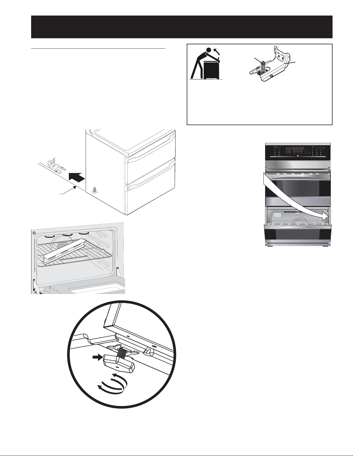
INSTRUCCIONES PARA INSTALACIÓN DE LA ESTUFA ELÉCTRICA DE 30”
C. Nivele la cocina y coloque la cocina en su lugar. -
Deslice la estufa a su lugar. Colocar la pata niveladora
dentro de la fi jacione de anti-inclinación. Verifi que
visualmente que las fi jaciones de anti-inclinación estén
correctamente enganchados (anclados). Nivele la cocina.
Nivele la estufa si es necesario, ajustando las 4 patas
niveladoras con una llave ajustable. Para verifi car que
la cocina esta nivelada coloque un nivel en las parrillas
interior del horno. Tome mínimo 2 lecturas con el nivel,
coloque el nivel en diagonal para que la cocina este
nivelada de atrás hacia adelante, si es necesario ajuste
las patas niveladoras.
Deslice
la estufa
Estufa lado
Range side
Figura 3
Tornillo
nivelador
de la
estufa
Fijaciones
de antiinclinación
Para verifi car si la fi jaciones de anti-inclinación está
instalado correctamente, sostenga el borde trasero
de la parte trasera de la estufa usando ambos
brazos. Intente inclinar la estufa hacia adelante con
cuidado. Si está instalada correctamente, la estufa
no debería inclinarse hacia adelante.
4. Placa de Identifi cación
Esta placa de
identifi cación está
localizada sobre el
marco y se puede ver
cuando la gaveta está
abierta. Consulte la
placa de identifi cación
para obtener la siguiente
información:
A. Números de modelo,
partida y serie de la
estufa.
B. Tasa de kilovatios
(requerimientos de
energía.)
C. Tasa de voltaje.
Figura 6
Figura 4
Patas
niveladoras
Bajar
Levantar
Figura 5
3
Page 10
INSTRUCCIONES PARA INSTALACIÓN DE LA ESTUFA ELÉCTRICA DE 30”
5. Requisitos de conexión eléctrica
Este aparato debe estar instalado en forma apropiada
y puesto a tierra por un técnico califi cado, de acuerdo
con el National Electric Code (Código Nacional de
Electricidad) ANSI/NFPA No. 70 —última edición— y
con los requerimientos de electricidad de los códigos
locales.
Este aparato puede ser conectado por medio de una
extensión a un tomacorriente local permanente o por
medio de “Juego de Cordón para el Suministro de
Energía”
Cuando se use la extensión, no deje exceso de alambre
en el compartimiento de la estufa. Si se deja exceso de
alambre en el compartimiento, ésto no permitirá que la
cubierta de acceso sea cerrada en forma apropiada,
lo cual puede crear un riesgo eléctrico potencial si se
perforan los alambres. Cuando se use conduit fl exible o
cable para estufas, use un conector fl exible o cable de
estufa resistente a tensiones.
NOTA: Use solamente alambre de cobre en la conexión
al bloque terminal.
5.1 Modelos que requieren Juego de Cordón para el
Suministro de Energía
El utilizador es responsable de la conexión del cable del
suministro eléctrico al bloque de conexión situado detrás
del panel de acceso.
El electrodoméstico se puede conectar a través de un
cableado permanente “cableado duro”; cable de cobre
blindado armado o cable no-metálico fl exible (cuando el
código local lo permite) o por medio de un kit de cable de
alimentación. Vea la gráfi ca (en la página siguiente) para
encontrar el tamaño mínimo del cable a utilizarse (el listado
general de la UL, código local puede diferenciar).
NOTA: La cocina corrediza eléctrica viene de fabrica
con un agujero de diámetro 1 1/8" (2.9 cm) come se
muestra en la fi gura 9. Si un agujero mas largo está
necesario retire la arandela de la pre-cortada.
El riesgo de fuego o de choque
eléctrico puede aparecer si usa el tamaño de cable
incorrecto, si las instrucciones de instalación no son
seguidas o si retira la abrazadera de releva.
Para casas sobre ruedas, nuevas instalaciones, en los
vehículos de recreativos o en las lugares donde los
códigos locales no permiten la conexión del conductor
de tierra al neutro, un ensamble de suministro eléctrico de
4 conductores para estufas, califi cado a 125/250 voltios
mínimo, 50 Amperes mínimo, debe de ser utilizado (ver la
fi gura 10). Si se utiliza un circuito 50A, un cable eléctrico
50A debe ser utilizado.
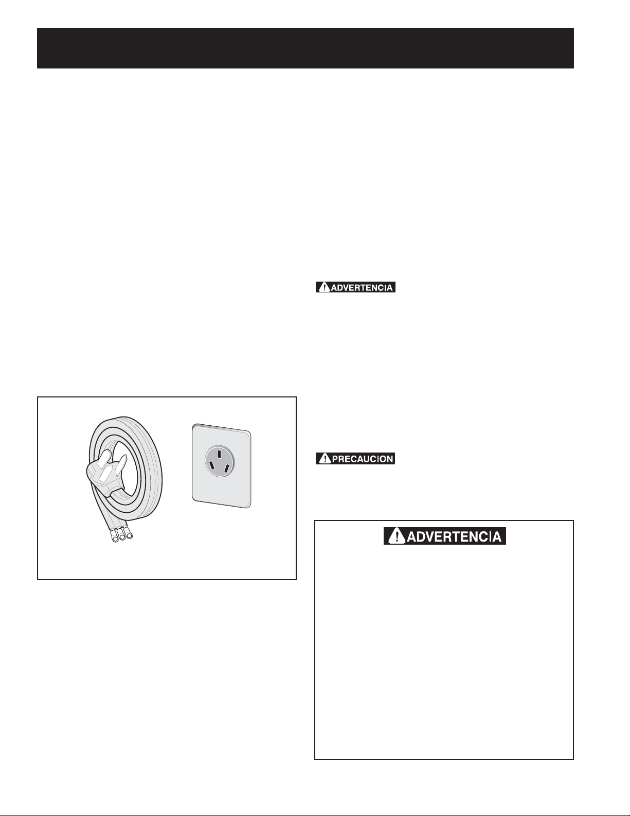
Figura 7 – Juego de cordón de 3 alambres
No desajuste las tuercas que
aseguran la conexión de la cocina al bloque terminal
cuando esté instalándola. El corte o la perdida de
corriente eléctrica puede ocurrir.
Peligro de choque eléctrico
• La conexión a tierra es requerida para este
electrodoméstico.
• No conecte al suministro eléctrico hasta que
el electrodoméstico este conectado a tierra de
manera permanente.
• Desconecte el suministro eléctrico hacia la caja de
empalmes antes de hacer la conexión eléctrica.
• Este electrodoméstico debe ser conectado a un
sistema de alambres permanentes, metálicos,
conectados a tierra o una puesta a tierra debe ser
conectada al terminal de tierra o un emplomados
al electrodoméstico.
El no seguir ninguna de estas instrucciones podría
causar fuego, heridas personales o choques eléctricos.
4
Page 11
INSTRUCCIONES PARA INSTALACIÓN DE LA ESTUFA ELÉCTRICA DE 30”
Este electrodoméstico fue fabricado
con el marco aterrizado a través de una correa de
conexión entre el neutral de la fuente de alimentación
y el marco. Si es utilizado en los E.E. U.U., con un
circuito nuevo de instalación (1996 NEC), en casa
sobre ruedas o vehículo recreativo, donde el código
local no permite el atterizaje a través del cable
neutro (blanco) o en Canadá; remueva la correa de
aterrizaje del marco y corte el otro extremo, cerca de
la terminal de neutral. Conecte el electrodoméstico
de la forma usual.
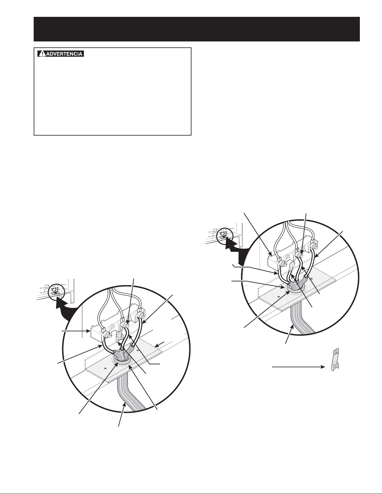
Conexión del cable a tres alambres la cocina
Si los códigos locales permiten la conexión del conductor a
tierra del armazón al alambre neutral del cable de bronce
del suministro eléctrico (vea fi gura 8).
1. Retire los tornillos de la parte baja de la cubierta
del cable trasero (cubierta de acceso), para tener
acceso al bloque de conexión del borne terminal.
2. Utilizar los tuercas suministraron en el paquete
de la literatura para conectar la parte neutral
del cable de bronce de suministro eléctrico al
terminal plateado que se encuentra al centro del
bloque terminal y, conectar los otros alambres a
los terminales externos. Aparee los alambres y los
terminales según el color (alambres rojos conectados
al terminal derecho, alambres negros conectados al
terminal izquierdo) (vea fi gura 8).
3. Baje la cubierta del terminal y vuelva al colocar los
tornillos.
Bloque
terminal
Alambre
Negro
Terminal plata
Alambre
rojo
Cordón de
la placa de
montaje
Neutro
(Alambre
Blanco)
Banda de
puesta a
tierra
Conexión del cable de cuatro conductores a la
cocina
1. Retire los tornillos de la parte baja de la cubierta
del cable trasero (cubierta de acceso), para tener
acceso al bloque de conexión del borne terminal.
2. Retire la correa de la base del bloque terminal
y del armazón del electrodoméstico. Retenga el
tornillo de la base.
3. Utilizar los tuercas suministraron en el paquete de
la literatura para conectar el alambre de tierra
(verde) del cable de bronce del suministro eléctrico
al armazón del electrodoméstico con el tornillo de la
base, usando el hoyo del armazón por donde retiró
la correa de la base (vea fi gura 9).
4. Conecte el alambre neutral (blanco) del cable de
cobre del suministro eléctrico al terminal plateado
del centro del bloque terminal y, conecte los otros
alambres a los terminales externos.
5. Baje la cubierta del terminal y vuelva al colocar los
tornillos.
Bloque terminal
Alambre
Negro
1 1/8" (2.9 cm)
Dia. Agujero
de la conexión
directa. Retira
la arandela precortada para 1
3/8" (3.5 cm)
dia. agujero.
Una arazadera de
releva provista debe de
estar instalada a está
ubicación.
NOTA: Asegúrese de
quitar la banda de puesta
a tierra provista.
Hacia el 240 V
receptáculo
Figura 9
Terminal plata
Alambre
Rojo
Neutro
(Alambre
Blanco)
Puesta a
tierra (cable
de cobre)
Una arazadera de
releva provista debe de
estar instalada a está
ubicación.
Hacia el 240 V
Receptáculo.
Figura 8
1 1/8" (2.9 cm)
Agujero de la
conexión directa.
Retira la arandela
pre-cortada para
1 3/8" (3.5 cm)
Dia. agujero.
5
Page 12
INSTRUCCIONES PARA INSTALACIÓN DE LA ESTUFA ELÉCTRICA DE 30”
Conexión eléctrica directa al corta circuito, a la caja
de fusibles o la caja de empalmes
Si el aparato está conectado directamente al corta
circuito, a la caja de fusibles o a la caja de empalmes,
use un cable blindado fl exible o no metálico recubierto
de cobre (con alambre a tierra). Provee una abrazadera
releva de anclaje homólogo UL a cada extremidad
del cable. A la extremidad del electrodoméstico, el
cable pase a través del agujero de la conexión directa
(ver fi gura 9) en el cordón de la placa de montaje. El
tamaño de los alambres (alambre de cobre solamente)
y las conexiones deben estar conforme al régimen del
electrodoméstico.
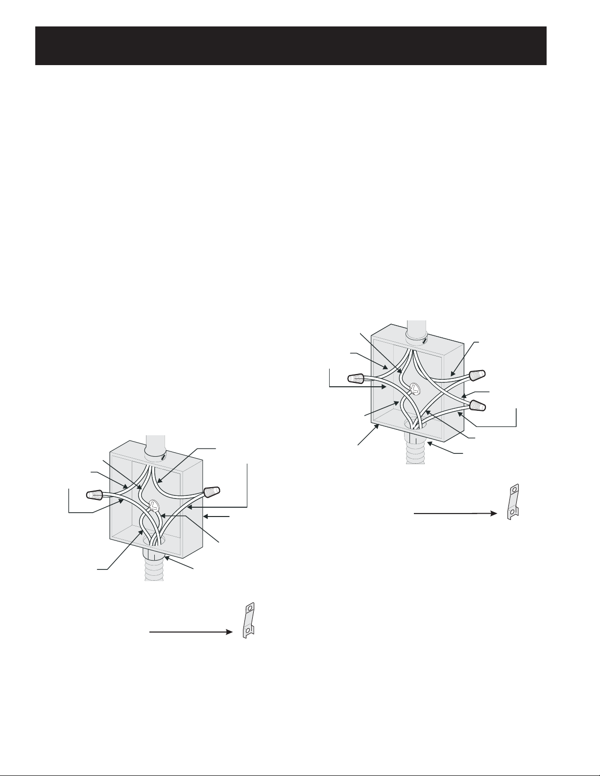
Donde los códigos locales permitan conectar el conductor
de puesta a tierra del electrodoméstico al neutral (blanco)
(vea fi gura 5):
1. Desconecte el suministro eléctrico.
2.
Siga las instrucciones en la página anterior para la
conexión del alambre de cuatro conductores a la
cocina (Fig. 9).
3. En el corta circuito, la caja de fusibles o la caja de
empalmes (Fig. 10):
a) Conecte el alambre verde (o cobre desnudo), el
alambre blanco del cable del electrodoméstico y
el alambre neutral (blanco) juntos.
b) Conecte los dos alambres negros juntos.
c) Conecte los dos alambres rojos juntos.
Cable de la fuente de
alimentación
Alambre
neutro (blanco)
Alambres
rojos
Alambres
negros
Donde los códigos locales NO permitan conectar el
conductor de puesta a tierra del electrodoméstico al
neutral (blanco), o si está conectado con un sistema a 4
alambres (vea fi gura 11):
1. Desconecte el suministro eléctrico.
2.
Siga las instrucciones en la página anterior para la
conexión del alambre de cuatro conductores a la
cocina (fi g. 9).
3. En el cortacircuito, la caja de fusibles o la caja de
empalmes (Fig. 11):
a. Conecte el alambre blanco del cable del
electrodoméstico al alambre neutral (blanco).
b. Conecte los 2 alambres negros juntos.
c. Conecte los 2 alambres rojos juntos.
d. Conecte el alambre verde (o de cobre desnudo)
de la puesta a tierra del alambre al alambre de
puesta a tierra del cortacircuito, de la caja de
fusibles o de la caja de empalmes.
Alambre
desnudo
o verde
Alambres
rojos
Alambre
desnudo
o verde
Caja de
empalmes
Cable de la fuente de
alimentación
Cable de la
estufa
Alambre
blanco
Alambres
negros
Alambre blanco
Conductor de
unión listado-UL
(o listado-CSA)
Alambre
desnudos o
verdes
Cable de la
NOTA: Asegúrese de quitar
la banda de puesta a tierra
provista.
estufa
Figura 10
Caja de
empalmes
Alambre
blanco
Conductor de
unión listado-UL
(listado-CSA)
NOTA: Asegúrese de quitar
la banda de puesta a tierra
provista.
Figura 11
Antes de llamar al servicio
Lea la sección Lista de Antes de llamar en su Manual
del Usuario. Esto le podrá ahorrar tiempo y gastos.
Esta lista incluye ocurrencias comunes que no son el
resultado de defectos de materiales o fabricación de
este artefacto.
Lea la garantía y la información sobre el servicio en su
Manual del Usuario para obtener el número de teléfono
gratuito y la dirección del servicio o llama
1-888-SU-HOGARSM.
6
 Loading...