

Kenmore 63016302400 Installation Manual
E L l T E
lnstaJtation instructions
Table of Contents
iMPORTANT iNSTRUCTiONS .............. 1
Tools Needed ............................................ 2
Materials Needed ...................................... 2
Materials Supplied ..................................... 3
Enclosure Preparation .............................. 4
Electrical Preparation ............................... 5
Plumbing Preparation ............................... 6
Dishwasher Preparation ........................... 7
Placing the Dishwasher ............................ 9
Securing the Dishwasher ....................... 10
Drain Hose Connection .......................... 10
Rot Water Connection ............................ 11
EJectricaJ Connection .............................. 12
Base and Toe PaneJ ................................ 13
RnaJ instructions ..................................... 13
Spanish Language Section ................ 14-26
Customer Service .................... Back Cover
iMPORTANT iNSTRUCTIONS - TO BE READ
WARNING - OBSERVE ALL WARNINGS AND CAUTIONS
These instructions are intended for use by qualified installers only.
tn addition to these instructions, the dishwasher
shall be installed:
Jn accordance with all local codes or, in the
absence of a local code,
Jnthe United States, with the National Electric
Code.
Jn Canada, with the Canadian Electric Code
C22.1 =latest edition/Provincial and
Municipal codes and/or local codes.
Read these installation instructions completely
and follow them carefully. They will save you time
and effort and help to ensure safety and optimum
dishwasher performance.
CAUTION: ff the dishwasher is installed in
a _ocation that experiences freezing tem-
peratures (e.g., in a holiday home), you
must drain aH the water from the
dishwasher's interior. Turn off the water
supply, disconnect the drain hose, and
allow your dishwasher to comp_etemy drain
into an appropriate receptacle°
m[V1PORTANT
The dishwasher drain hose must be installed
with a portion of it at least 20" (508ram) off the
cabinet floor; otherwise the dishwasher may not
drain properly.
The dishwasher is intended for residential use
only, and should not be used in commercial food
service establishments.
NEW INSTALLATION - Jf the dishwasher is a
new installation, most of the work must be done
before the dishwasher is moved into place.
REPLACEMENT - If the dishwasher is replac-
ing another dishwasher, check the existing
dishwasher connections for compatibility with the
new dishwasher, and replace parts as neces-
sary.
mnspect the Dishwasher
After unpacking the dishwasher and prior to
installation, thoroughly inspect the dishwasher
for possible freight or cosmetic damage. Report
any damage immediately. Cosmetic defects
must be reported within 5 days of installation.
NOTE: Do not discard any bags or items that
come with the original package until after the
entire installation has been completed.
iMPORTANT iNSTRUCTiONS
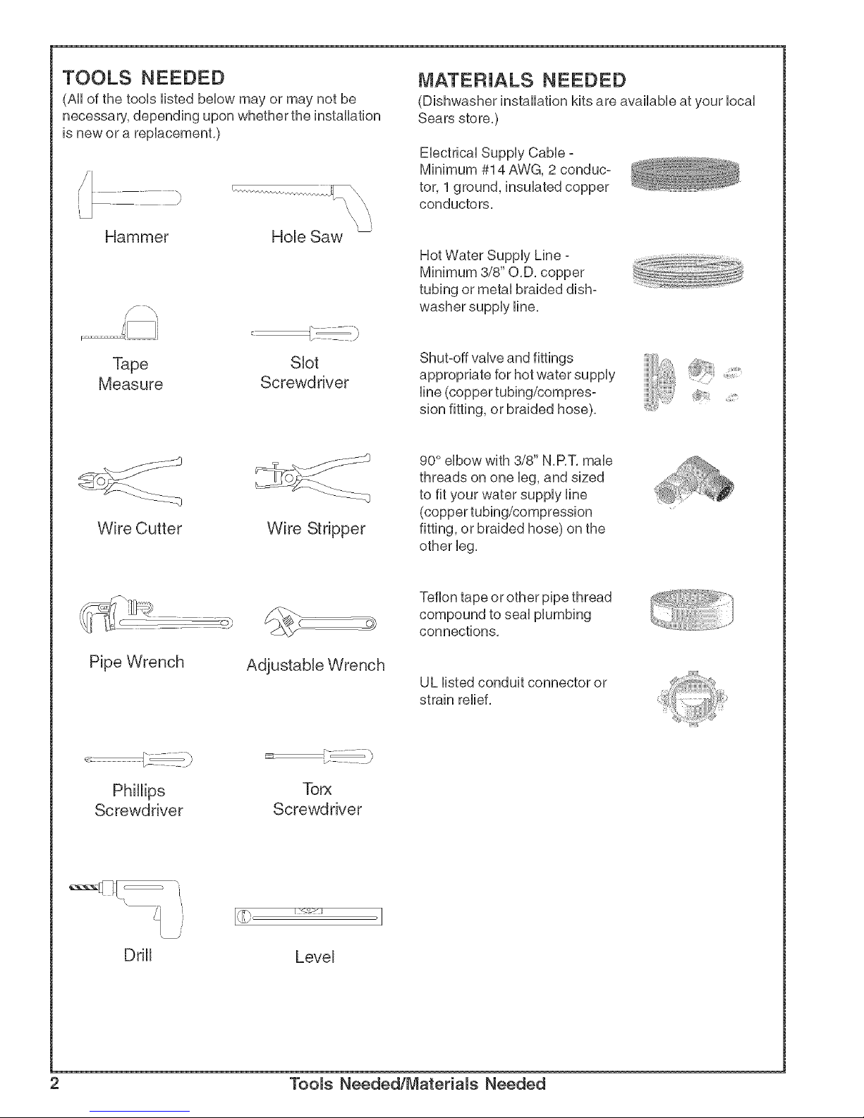
TOOLS NEEDED
(All of the tools listed below may or may not be
necessary, depending upon whether the installation
is new or a replacement.)
Hammer Hole Saw
MATERIALS NEEDED
(Dishwasher installation kits are available at your local
Sears store.)
Electrical Supply Cable -
Minimum #14 AWG, 2 conduc-
tor, 1 ground, insulated copper
conductors.
Hot Water Supply Line -
Minimum 3/8" O.D. copper
tubing or metal braided dish-
washer supply line.
Tape Slot
Measure Screwdnver
Shut-off valve and fittings
appropriate for hot water supply
line (copper tubing/compres-
sion fitting, or braided hose).
iiiiiiiiiii_;/i!]!!!!i_
Wire Cutter
Wire Stripper
90° elbow with 3/8" N.RT. male
threads on one leg, and sized
to fit your water supply line
(copper tubing/compression
fitting, or braided hose) on the
other leg.
<
Pipe Wrench
Adjustable Wrench
Teflon tape or other pipe thread
compound to seal plumbing
connections.
UL listed conduit connector or
strain relief.
Phil@s TOP,(
Screwdriver Screwdriver
Level
2 Tooms Needed/Materials Needed
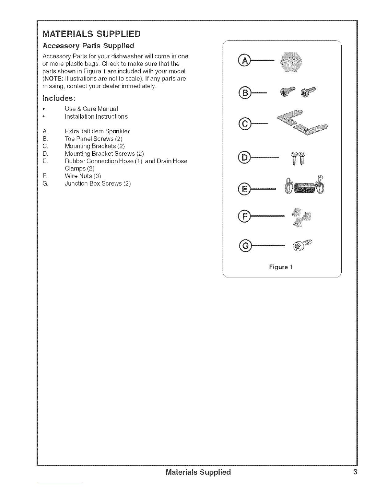
MATERIALS SUPPUED
Accessory Parts Supplied
Accessory Parts for your dishwasher will come in one
or more plastb bags, Check to make sure that the
parts shown in Figure 1 are included with your model
(NOTE: Hustrations are not to scab), if any parts are
missing, contact your deabr immediately,
hc_udes:
Use & Care Manual
Installation instructions
A,
B,
C,
D,
E,
F,
G,
Extra Tall item Sprinkler
Toe Panel Screws (2)
Mounting Brackets (2)
Mounting Bracket Screws (2)
Rubber Connection Hose (1) and Drain Hose
Clamps (2)
Wire Nuts (8)
Junction Box Screws (2)
®
@
®
®
@
Materials Supplied 3
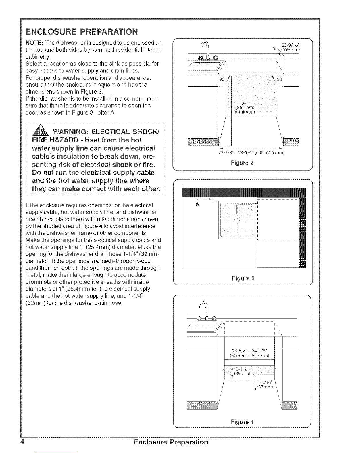
ENCLOSURE PREPARATION
NOTE: The dishwasher is designed to be enclosed on
the top and both sides by standard residential kitchen
cabinetry.
Select a location as close to the sink as possible for
easy access to water supply and drain lines.
For proper dishwasher operation and appearance,
ensure that the enclosure is square and has the
dimensions shown in Figure 2.
if the dishwasher is to be installed in a corner, make
sure that there is adequate clearance to open the
door, as shown in Figure 3, letter A.
WARNmNG: ELECTmCAL SHOCK/
FIRE HAZARD o Heat from the hot
water supply Hne can cause e_ectrica_
cable's insulation to break down, preo
senting risk of e_ectrica_ shock or fire.
Do not run the e_ectrica_ supply cable
and the hot water supply Hne where
they can make contact with each other.
if the enclosure requires openings for the electrical
supply cable, hot water supply line, and dishwasher
drain hose, place them within the dimensions shown
by the shaded area of Figure 4 to avoid interference
with the dishwasher frame or other components.
Make the openings for the electrical supply cable and
hot water supply line 1" (25.4mm) diameter. Make the
opening for the dishwasher drain hose 1-1/4" (32mm)
diameter, if the openings are made through wood,
sand them smooth, if the openings are made through
metal, make them large enough to accomodate
grommets or other protective sheaths with inside
diameters of 1" (25.4mm) for the electrical supply
cable and the hot water supply line, and 1ol/4"
(32ram) for the dishwasher drain hose.
23o9/I6"
(598mm)
i \
23-5/8" - 24-I/4" (600-616 mm
Figure 2
J
'1
_/i I\
/f_ ix \
I
23-5/8" - 24-1/8"
(600mm - 6! 3mm)
Figure 4
4 Enclosure Preparation
ELECTRICAL PREPARATION
,_ WARNmNG: ELECTRICAL SHOCK
HAZARD - Working on an energized
circuit could result in serious injury or
death. Only qualified electricians should
perform electrical work. Do not attempt
any work on the dishwasher electric
supply circuit until you are certain the
circuit is de-energized.
WARNmNG: FIRE HAZARD - ram-
proper electrical work can cause fire.
Only qualified electricians should per-
form e_ectrica[ work.
Electrical Supply
The customer has the responsibility of ensuring that the
dishwasher electrical installation is in compliance with
all national and local electrical codes and ordinances.
The dishwasher is designed for an electrical supply of
120V, 60 Hz, AC, connected to a dishwasher-dedicated,
properly grounded electrical circuit with a fuse or breaker
rated for 15 amps. If the dishwasher is connected with a
food disposer, a 20 amp (and no higher) fuse or circuit
breaker may be used. Electrical supply conductors shall
be a minimum #14 AWG copper wire.
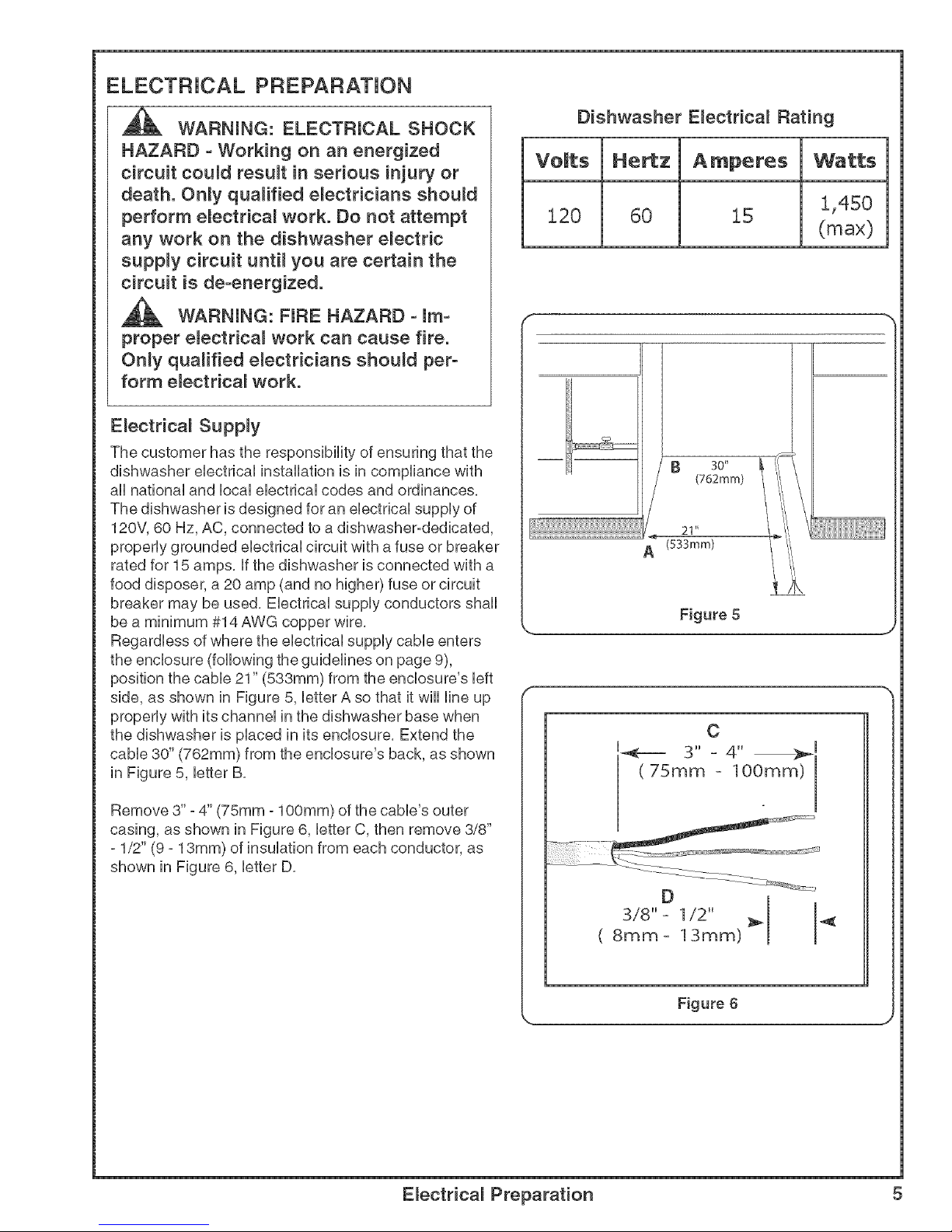
Regardless of where the electrical supply cable enters
the enclosure (following the guidelines on page 9),
position the cable 21" (533mm) from the enclosure's left
side, as shown in Figure 5, letter A so that it will line up
properly with its channel in the dishwasher base when
the dishwasher is placed in its enclosure. Extend the
cable 30" (762mm) from the enclosure's back, as shown
in Figure 5, letter B.
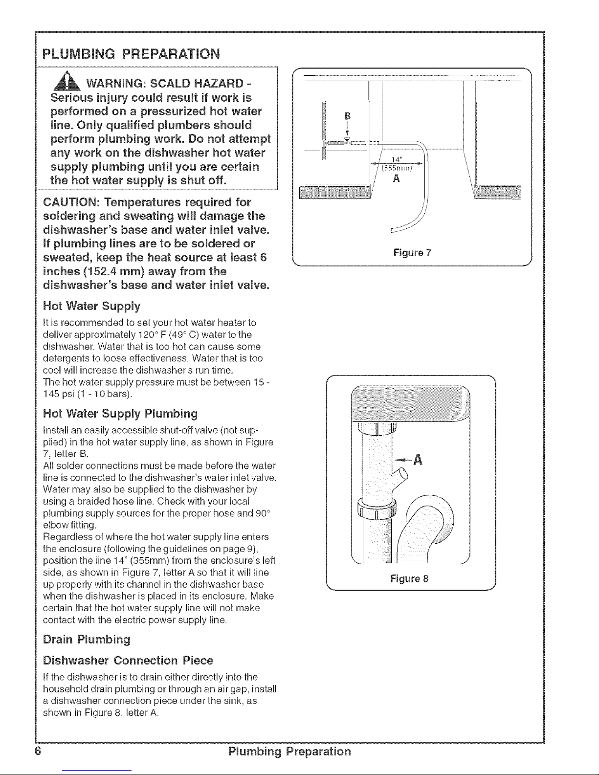
Remove 3" - 4" (75mm - 100mm) of the cable's outer
casing, as shown in Figure 6, letter C, then remove 3/8"
- 1/2" (9 - 13mm) of insulation from each conductor, as
shown in Figure 6, letter D.
Dishwasher Electrical Rating
Ve[ts He_z Amperes Watts
120 60 15 1,450
(max)
f ",
1
[} 30"
(762mm)
L 21"
(533mm)
Figure 5
_., J
C
u_=== 3" = 4" _[
(75ram = 100ram)
D
3/8" = 1/2"
( 8ram- 13ram)
Figure 6
Electrical Preparation 5
PLUMBING PREPARATION
CAUTmON: Temperatures required for
so{dering and sweating will damage the
dishwasher's base and water inlet valve.
ff p{umbing lines are to be soldered or
sweated, keep the heat source at _east 6
inches (152.4 ram) away from the
dishwasher's base and water in_et valve.
Hot Water Supply
it is recommended to set your hot water heater to
deliver approximateUy 120° F (49° C) water to the
dishwasher, Water that is too hot can cause some
detergents to bose effectiveness, Water that is too
cooUwHUincrease the dishwasher's run time,
The hot water supply pressure must be between 15 -
145 psi (1 - 10 bars),
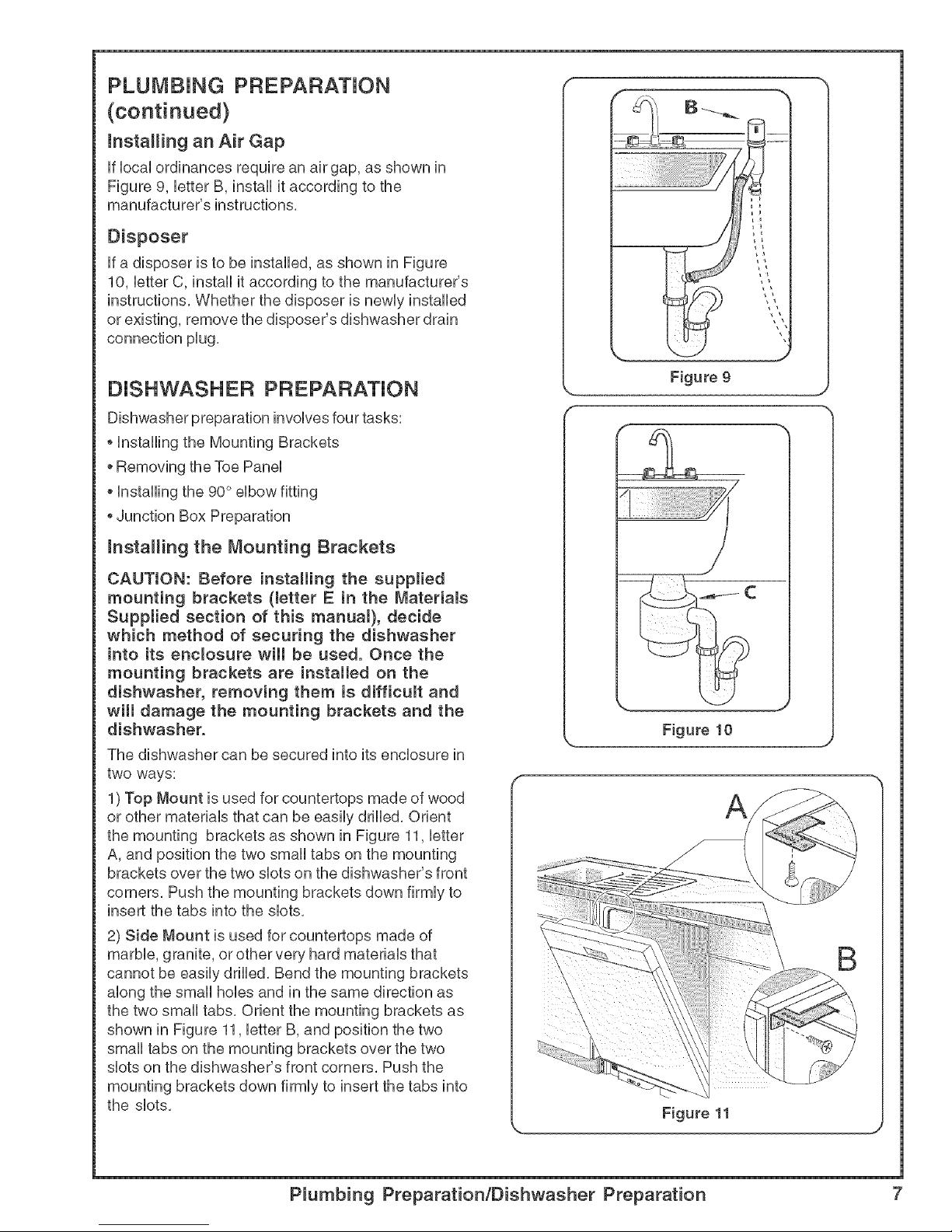
Hot Water Supply P_umbing
Install an easily accessible shut-off valve (not sup=
plied) in the hot water supply line, as shown in Figure
7, letter B,
All solder connections must be made before the water
line is connected to the dishwasher's water inlet valve,
Water may also be supplied to the dishwasher by
using a braided hose line, Check with your local
plumbing supply sources for the proper hose and 90°
elbow fitting,
Regardless of where the hot water supply line enters
the enclosure (following the guidelines on page 9),
position the line 14" (355mm) from the enclosure's left
side, as shown in Figure 7, letter A so that it wiii line
up properly with its channel in the dishwasher base
when the dishwasher is placed in its enclosure, Make
certain that the hot water supply line will not make
contact with the electric power supply line,
Drain P_umbing
Dishwasher Connection Piece
If the dishwasher is to drain either directly into the
household drain plumbing or through an air gap, install
a dishwasher connection piece under the sink, as
shown in Figure 8, btter A,
Figure 8 J
6 P_umbing Preparation
PLUMBING PREPARATION
(continued)
hstaHing an Air Gap
if local ordinances require an air gap, as shown in
Figure 9, letter B, install it according to the
manufacturer's instructions,
Disposer
if a disposer is to be installed, as shown in Figure
10, letter C, install it according to the manufacturer's
instructions, Whether the disposer is newly installed
or existing, remove the disposer's dishwasher drain
connection plug,
DISHWASHER PREPARATION
Dishwasher preparation involves four tasks:
o Installing the Mounting Brackets
oRemoving the Toe Panel
Installing the 90 ° elbow fitting
Junction Box Preparation
hstaHing the Mounting Brackets
CAUTION: Before installing the supplied
mounting brackets (metter E in the Materials
Supplied section of this manual), decide
which method of securing the dishwasher
into its encmosure wHmbe used. Once the
mounting brackets are installed on the
dishwasher, removing them is difficult and
will damage the mounting brackets and the
dishwasher.
The dishwasher can be secured into its enclosure in
two ways:
1)Top Mount is used for countertops made of wood
or other materials that can be easily drilled, Orient
the mounting brackets as shown in Figure 11, letter
A, and position the two small tabs on the mounting
brackets over the two slots on the dishwasher's front
corners, Push the mounting brackets down firmly to
insert the tabs into the slots.
2) Side Mount is used for countertops made of
marble, granite, or other very hard materials that
cannot be easily drilled. Bend the mounting brackets
along the small hobs and in the same direction as
the two small tabs. Orient the mounting brackets as
shown in Figure 11, letter B, and position the two
small tabs on the mounting brackets over the two
slots on the dishwasher's front corners. Push the
mounting brackets down firmly to insert the tabs into
the slots.
Figure 9
Figure 10
P_umbing Preparation/Dishwasher Preparation 7
DISHWASHER PREPARATION
(continued}
Removing the Toe Panel
Regular Toe Panel
The toe paneHis HooseHyattached with tape, Remove
the tape and puHHthe toe paneHaway from the dish=
washer, Set the toe paneHaside, HtwHHbe reinstaHHed
Hater,
hstaHing the 90 ° E_bow Fitting
NOTE: The 90 ° eHbowfitting is not supplied with the
dishwasher, and must be purchased separateHy(see
MateriaHs Needed section), Hfthe dishwasher's hot
water suppHyHneis to be copper tubing, make certain
the eHbowhas a compression fitting,
AppHyTeflon tape or other pipe seaHant when required,
Orient the hot water suppHyconnection Hegof the
eHbowtoward the channeH opening in the dishwasher
base,
NOTE: The white hose on the dishwasher's right side
paneHis a factory-instaHHedvent hose, not to be
confused with the gray drain hose, The vent hose
requires neither repositioning nor connecting by the
consumer,
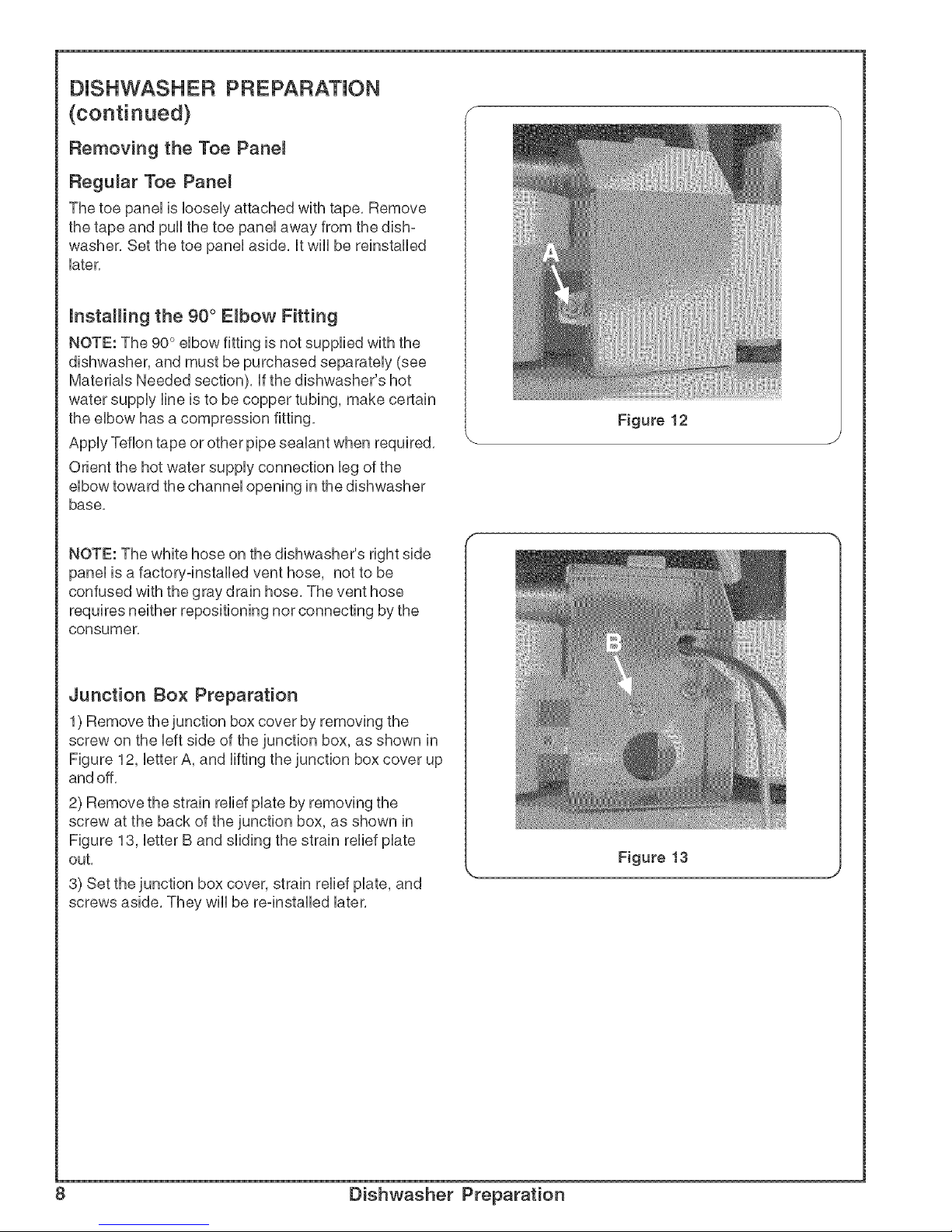
Junction Box Preparation
1) Remove the junction box cover by removing the
screw on the Heftside of the junction box, as shown in
Figure 12, HetterA, and HiRingthe junction box cover up
and off,
2) Remove the strain reHiefpilate by removing the
screw at the back of the junction box, as shown in
Figure 13, HetterB and sHidingthe strain reHiefpilate
out,
3) Set the junction box cover, strain reHiefpilate, and
screws aside, They wiHHbe re-instaHHedHater,
Figure 12
Figure 13
J
8 Dishwasher Preparation
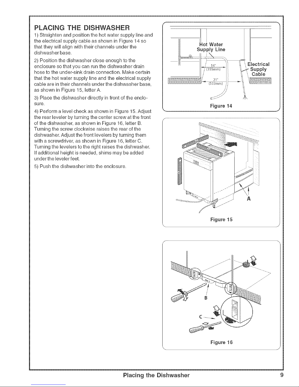
PLACING THE DISHWASHER
1) Straighten and position the hot water supply line and
the electrical supply cable as shown in Figure 14 so
that they wiii align with their channels under the
dishwasher base,
2) Position the dishwasher close enough to the
enclosure so that you can run the dishwasher drain
hose to the under-sink drain connection, Make certain
that the hot water supply line and the electrical supply
cable are in their channels under the dishwasher base,
as shown in Figure 15, letter A,
3) Place the dishwasher directly in front of the enclo-
sure,
4) Perform a level check as shown in Figure 15, Adjust
the rear leveler by turning the center screw at the front
of the dishwasher, as shown in Figure 16, letter B,
Turning the screw clockwise raises the rear of the
dishwasher, Adjust the front levelers by turning them
with a screwdriver, as shown in Figure 16, letter C,
Turning the levelers to the right raises the dishwasher,
if additional height is needed, shims may be added
under the leveler feet,
5) Push the dishwasher into the enclosure,
Hot Water
Supp[y Line
(355mm)
21"
(533mm)
Electrical
- Supply
Cable
Figure 14
A
Figure 15
Figure 16
Placing the Dishwasher £
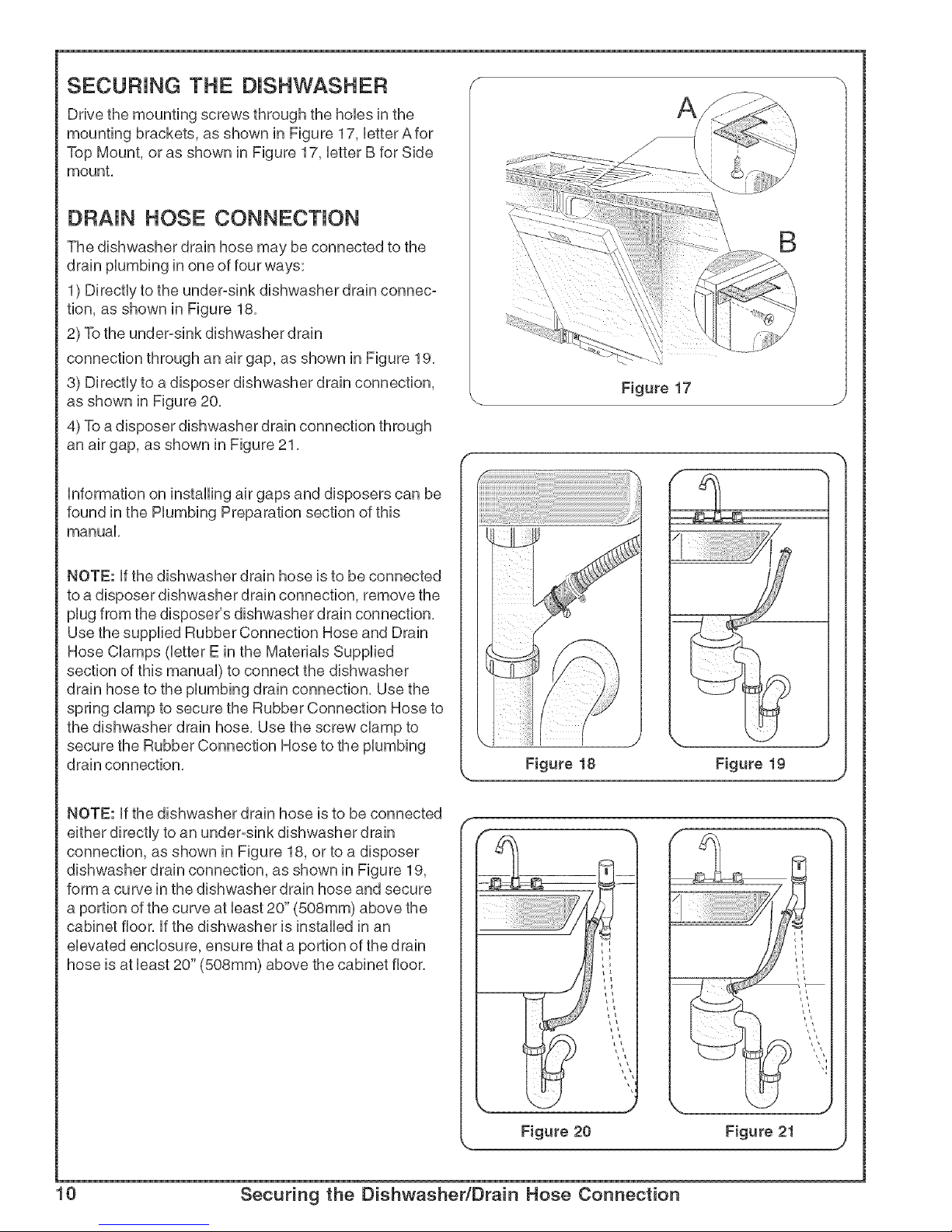
SECURING THE DISHWASHER
Drive the mounting screws through the hobs in the
mounting brackets, as shown in Figure 17, letter A for
Top Mount, or as shown in Figure 17, letter B for Side
mount.
DF{AJN HOSE CONNECTION
The dishwasher drain hose may be connected to the
drain plumbing in one of four ways:
1) Directly to the under-sink dishwasher drain connec-
tion, as shown in Figure 18.
2) To the under-sink dishwasher drain
connection through an air gap, as shown in Figure 19.
3) Directly to a disposer dishwasher drain connection,
as shown in Figure 20.
4) To a disposer dishwasher drain connection through
an air gap, as shown in Figure 21.
\
\
B
Figure 17
information on installing air gaps and disposers can be
found in the Plumbing Preparation section of this
manual.
NOTE: if the dishwasher drain hose is to be connected
to a disposer dishwasher drain connection, remove the
plug from the disposer's dishwasher drain connection.
Use the supplied Rubber Connection Hose and Drain
Hose Clamps (letter E in the Materials Supplied
section of this manual) to connect the dishwasher
drain hose to the plumbing drain connection. Use the
spring clamp to secure the Rubber Connection Hose to
the dishwasher drain hose. Use the screw clamp to
secure the Rubber Connection Hose to the plumbing
drain connection.
NOTE: if the dishwasher drain hose is to be connected
either directly to an under-sink dishwasher drain
connection, as shown in Figure 18, or to a disposer
dishwasher drain connection, as shown in Figure 19,
form a curve in the dishwasher drain hose and secure
a portion of the curve at bast 20" (508mm) above the
cabinet floor, if the dishwasher is installed in an
elevated enclosure, ensure that a portion of the drain
hose is at bast 20" (508ram) above the cabinet floor.
Figure 20 Figure 21
J
10 Securing the Dishwasher/Drain Hose Connection
 Loading...