

Page 1

KENMORE ELITE
DISHWASHERS
630.13952
630.13953
630.13959
Sears Brands Management Corporation
Hoffman Estates, IL 60179 U.S.A.
www.sears.ca
www.kenmore.com
www.sears.com
Sears Canada Inc.
Toronto, Ontario, Canada M5B 2C3
702_58300000149896_ara_en_b
Page 2

SAFETY
I. SAFETY...................................................................................... 3
IA. General hazards..........................................................................................................3
IB. Electrical shock / fire hazards ...................................................................................3
IC. Plumbing / scalding hazards .....................................................................................3
II. INSTALLATION.......................................................................... 4
IIA. Pre-Install checklist....................................................................................................4
IIB. Alignment.................................................................................................................... 4
IIC. Electrical connection .................................................................................................5
IID. Water connection .......................................................................................................6
IIE. Drain and condensation hose connections .............................................................6
III. OPERATION............................................................................... 7
IIIA. Control layout .............................................................................................................7
IIIB. Features ......................................................................................................................7
IIIC. Entering special programs and coding .................................................................... 8
IV. COMPONENTS ........................................................................ 12
IVA. Dishwasher components .........................................................................................12
V. REPAIR .................................................................................... 28
VA. Disassembly procedures .........................................................................................28
VB. Water valves..............................................................................................................31
VC. Circulation pumps.................................................................................................... 31
VD. Controls.....................................................................................................................32
VE. Heaters ......................................................................................................................34
VF. 2-piece drain hose connection ................................................................................36
VG. Drain pumps..............................................................................................................36
VH. Dispensers ................................................................................................................36
VI. Door latches.............................................................................................................. 37
VI. FAULT DIAGNOSTICS ............................................................ 39
VIA. Customer service test program...............................................................................39
VIB. Troubleshooting .......................................................................................................42
VII. TECHNICAL SPECIFICATIONS.............................................. 49
VIII. WIRING DIAGRAMS................................................................ 50
702_58300000149896_ara_en_b
Page 3

SAFETY
I. SAFETY
IA. General hazards
Don’t use the dishwasher until it is completely installed. When opening the door on an
uninstalled dishwasher, carefully open the door while supporting the rear of the unit.
Failure to follow this warning can cause the dishwasher to tip over and result in serious
injury.
In some conditions, hydrogen gas can form in a hot water system that has not been
used for weeks. Hydrogen gas is explosive. Before filling a dishwasher from a system
that has been off for weeks, run the water from a nearby faucet in a well ventilated
area until there is no sound or evidence of gas.
Temperatures required for soldering and sweating will damage the dishwasher’s base
and water inlet valve. If plumbing lines are to be soldered or sweated, keep the heat
source at least 6 inches (152.4 mm) away from the dishwasher’s base and water inlet
valve.
Removing any cover or pulling the dishwasher from the cabinet can expose hot water
connections, electrical power and sharp edges or points. Handle with care. Always
wear gloves and safety glasses.
IB. Electrical shock / fire hazards
m
c h
Don’t allow electrical and water supply lines to touch. Don’t work on an energized
circuit. Doing so could result in serious injury or death. Only qualified electricians
should perform electrical work. Don’t attempt any work on the dishwasher electric
supply circuit until you are certain the circuit is de-energized.
Make sure electrical work is properly installed. There should be no loose electrical
connections. Ensure all electrical connections are properly made.
The customer has the responsibility of ensuring that the dishwasher electrical
installation is in compliance with all national and local electrical codes and ordinances.
The dishwasher is designed for an electrical supply of 120VAC, 60 Hz, connected to a
dishwasher-dedicated, properly grounded electrical circuit with a fuse or breaker rated
for 15 amps. Electrical supply conductors shall be a minimum #14 AWG copper only
wire rated at 75°C (167°F) or higher.
This appliance must be connected to a grounded metal, permanent wiring system, or
an equipment-grounding conductor must be run with the circuit conductors and
connected to the equipment-grounding terminal or lead on the appliance. Don’t use
extension cords.
IC. Plumbing / scalding hazards
Don’t perform any work on a charged hot water line. Serious injury could result. Only
qualified plumbers should perform plumbing work. Don’t attempt any work on the
dishwasher hot water supply plumbing until you are certain the hot water supply is shut
off.
m
702_58300000149896_ara_en_b
Page 4
INSTALLATION
Don’t over tighten the 90° elbow. Doing so may damage the water inlet valve and
cause a water leak. Temperatures required for soldering and sweating will damage
the dishwasher’s water inlet valve. If plumbing lines are to be soldered or sweated,
keep the heat source at least 6 inches (152.4 mm) away from the dishwasher’s water
inlet valve.
Check local plumbing codes for approved plumbing procedures and accessories. All
plumbing should be done in accordance with national and local codes.
These instructions depict an installation method for stainless steel braided hose or
PEX hot water supply lines. If using copper tubing or other material for water supply,
defer to a licensed plumber for proper installation.
II. INSTALLATION
IIA. Pre-Install checklist
Unpack unit. Retain packing material until installation is successful. Remove
packing material from inside the dishwasher.
Inspect parts to ensure you have all the necessary materials.
Flush household hot water supply for at least two minutes.
Measure the enclosure area. The opening must be at least 34" (87 cm) high and
23-5/8" (60-61 cm) wide.
The opening must be close enough to the sink for water line and drain hose
plumbing access.
Unit must be installed close enough to the sink so that drain hose length does not
exceed 92" (234 cm) and a high loop is raised at least 20" (51 cm) above the floor.
Wooden openings must be sanded smooth and metal openings must be covered
by a protective gasket.
Is your water heater set at 120°F (49°C) and does water pressure measure 15-145
psi (1-10 bar)?
If installing in a corner, the dishwasher door must clear cabinet hardware.
Determine mounting method based on dishwasher model and countertop type,
whether top or side mount.
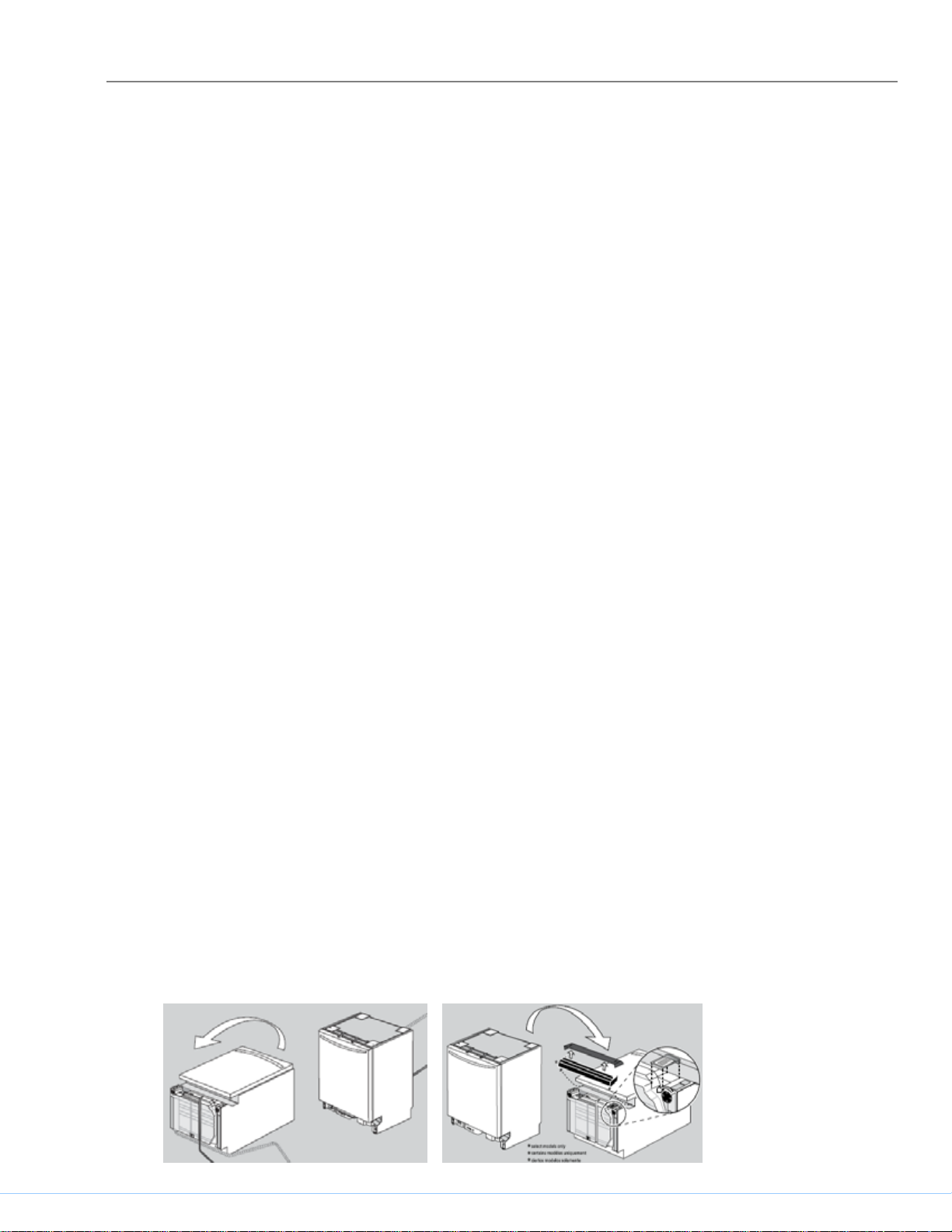
IIB. Alignment
Gently rest the unit on its back, taking care not to crush the drain hose. Remove the
toe panel(s). Loosen front feet slightly. Remove junction box cover and retain for later
use. Place dishwasher upright, then level side to side and front to back.
702_58300000149896_ara_en_b
Page 5
INSTALLATION
If your dishwasher has pre-attached mounting brackets and you have a wooden
under-counter, position brackets as far apart as possible by sliding them within slots in
direction of arrows. Do not attach them to the countertop yet.
If your dishwasher has pre-attached mounting brackets and the counter top is stone,
use pliers to rotate bracket flanges to remove brackets from the top. Grasp brackets
with pliers at perforation and bend until the rounded end breaks free. Discard the
ends. Slip brackets through side slots. Using pliers, bend bracket flanges so the
brackets will not slip through slots. Do not attach them to the countertop yet.
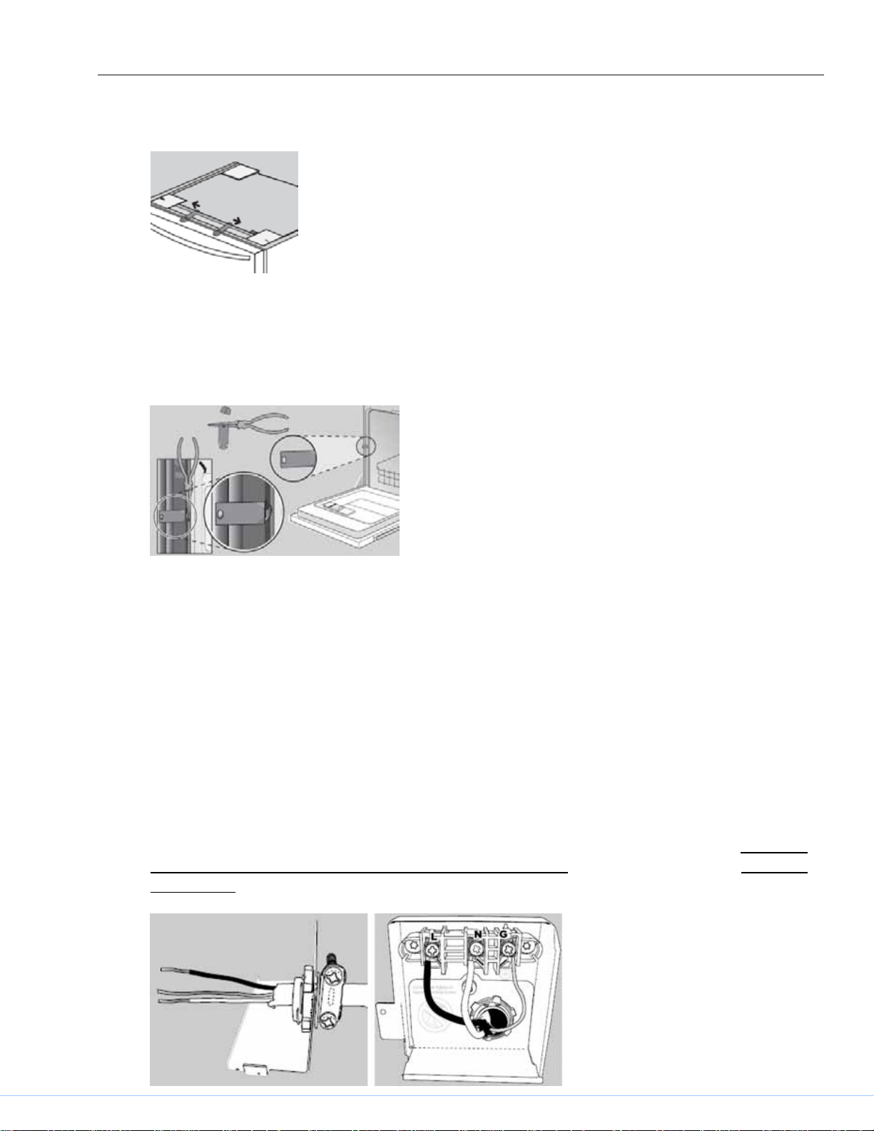
IIC. Electrical connection
Install according to national and local codes.
Carefully place dishwasher on its back to make electrical connections to the terminal
block. Turn power off at the fuse box. Extend power cord approximately 21” from the
left side of the opening, and 30” from the back wall, making sure the cord doesn’t
contact any moving parts.
Strip outer casing of electrical wire to expose 2.5" - 3" (65 - 76 mm) of inner wires,
then strip 1/2" (13 mm) casing from each wire. If plugging the dishwasher into an
outlet, use an approved appliance power cord. Insert cord through a strain relief (not
included) and install to strain relief plate. Attach wires to terminal block (black – L
(hot), white – N (neutral) & green – G (ground). Unscrew terminal screws, but don’t
loosen or remove them as they may become damaged. Attach wires snugly, but don’t
overtighten.
702_58300000149896_ara_en_b
Page 6
INSTALLATION
IID. Water connection
Install according to national and local codes.
Carefully place dishwasher on its back to make water connections to the water inlet
valve. Use a 90º elbow fitting with Teflon tape as needed. Don’t overtighten.
Attach the hot water line to the 90° elbow and route it underneath the unit toward the
hot water connection. Make sure the line doesn’t contact any moving parts.
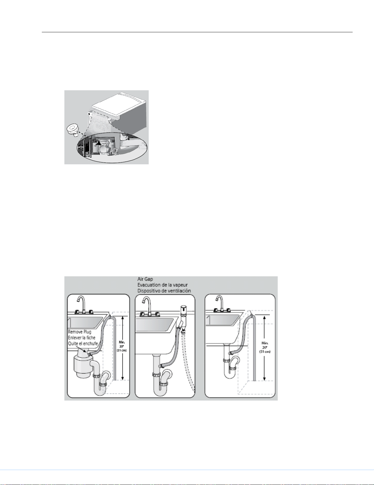
IIE. Drain and condensation hose connections
Plumbing installations will vary - refer to local codes. The maximum length of the drain
hose, including leading to an air gap (if any) is 150" (381 cm). Make sure a high loop
is raised at least 20" (51 cm) above the floor.
Drain hose has its own adapter – connect directly to plumbing connection and secure
with supplied hose clamp. Don’t connect to condensation hose.
702_58300000149896_ara_en_b
Page 7
OPERATION
III. OPERATION
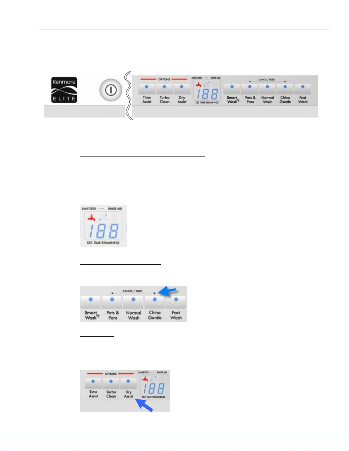
IIIA. Control layout
IIIB. Features
Sanitized and Refill Rinse Agent lights
The Sanitized light comes on after certain wash programs have finished,
showing dishes have been sanitized according to NSF standards. Check the
Use & Care Guide to confirm which programs qualify as NSF rated.
The Refill Rinse Agent light shows rinse-aid needs to be added.
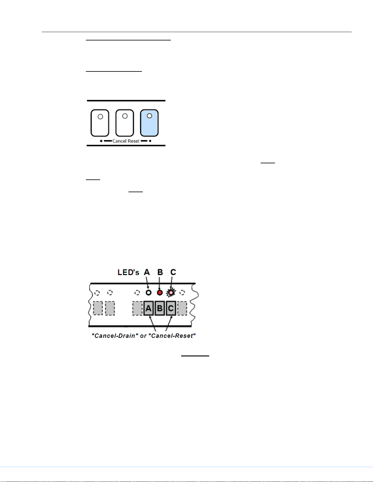
Reset (“Cancel – Reset”)
To reset, push Cancel-Reset buttons at the same time.
Dry Assist
With Dry Assist the temperature of the rinse water can be raised and the drying
time increased for improved drying.
702_58300000149896_ara_en_b
Page 8
OPERATION
Changing basic features
Some features can be changed on the fascia panel.
End of cycle tone
The End of cycle tone volume can be changed.
Turn the dishwasher off and then push and hold the right Cancel Reset button
while turning the dishwasher on – release buttons when a tone sounds or the
right Cancel Reset button LED lights up.
Pushing the right Cancel Reset button changes the setting – push it until the
tone is at the desired volume (or the tone stops if it’s to be turned off). Push the
on/off button to save the setting.
IIIC. Entering special programs and coding
Controls contain codes for sales demo mode, factory tests, customer service
test program, dishwasher configuration and error codes.
While pushing (and holding) any two wash cycle buttons, turn the dishwasher
on with the on/off switch. The current coding (e.g. “C2”) will show in the display
or LED's until you release the buttons. After releasing the buttons, LED “B” will
be lit and LED “C” will flash, confirming you’re in the special programs menu.
Push button “B” repeatedly until you’ve selected your desired program (see
P(X) Program codes, “P1” or “P4” -- programs “P0” and “P3” are factory tests
that aren’t to be used).
702_58300000149896_ara_en_b
Page 9

OPERATION
P(X) Program codes
P0 = Functional test - used for assembly (do not use)
P1 = Customer service test program (see E(X) error codes)
P3 = Endurance / Life test (do not use)
P4 = Control coding (see C(X) control codes)
E(X) Error codes
E0 = No errors
E1 = Heating error
E2 = NTC error
E3 = Filling error
E4 = Water switch cannot be positioned
E5 = Safety float water level reached
E6 = Aqua sensor error
C(X) Control codes
C9 = Sales demo mode
Codes C1 through C9 are possible, depending on the model.
HINT: Customers pushing and holding Cancel-Reset buttons while turning
dishwashers on can see strange displays. Whenever you get call about a
“strange” display, check if the customer put the dishwasher into the test
program or some other program.
Sales demo (showroom) program
Entering sales demo program
Enter the special program mode – see section IIIE. Before releasing the two
buttons held while you turned the dishwasher on, note the coding on the digital
display (e.g. “C2”) -- the dishwasher must be returned to this code for resale
.
Push button “B” repeatedly until the display shows sales demo program mode
“P4”. Push button “C” to confirm it.
Push button “B” repeatedly until the display shows sales demo code “C9”. Push
button “C” to confirm it.
Turn power off and then back on. The dishwasher is now in demo mode -- all
button lights will light up.
702_58300000149896_ara_en_b
Page 10
OPERATION
Preparing a dishwasher for showroom use
Turn off the power to the dishwasher or disconnect the dishwasher from the
electrical power.
WARNING
: Danger of electrical shock!
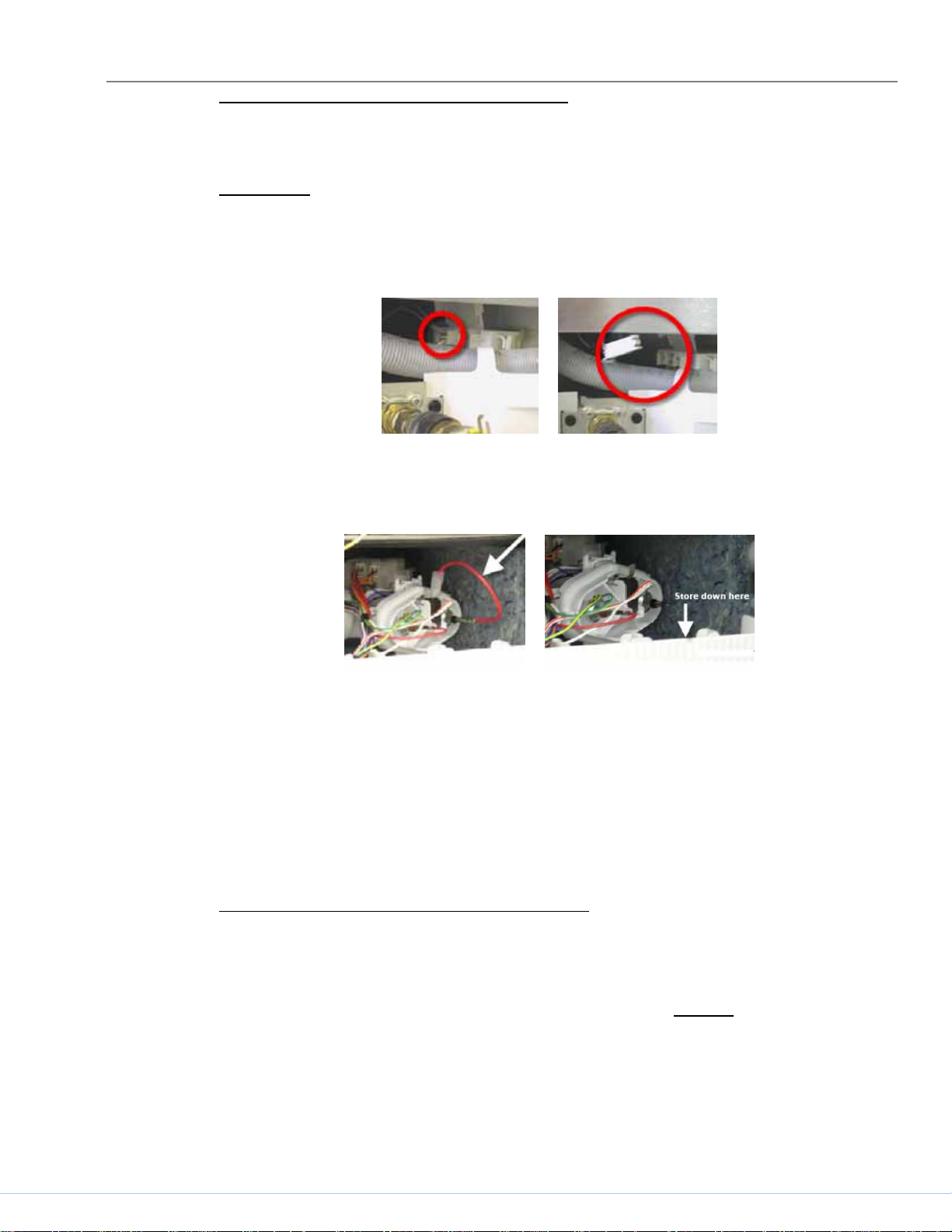
Remove the toe kick and locate the drain pump terminal shown below.
Disconnect the terminal from the drain pump by squeezing and pulling it out.
Cover the terminal with electrical tape to prevent electrical shock.
Disconnect both ends of the short heater red wire – see section 5.2.3 to remove
right side panel for access. Tape the wire with electrical tape to the plastic base
so it can be reconnected for resale.
Do NOT connect dishwasher to a water line, but slowly pour about 4.5 liters of
distilled water into the tank. The water level should be near the bottom of the
fine filter screen in the sump.
Add a small amount of rinse aid and a 1/2 capful of antibacterial agent
(bacteriastat) onto the inner door. Do NOT add bleach.
Reconnect the dishwasher and turn it on by pushing the on/off button. Close
the door and run dishwasher for one minute. If necessary, add more water until
level reaches the fine filter screen.
Preparing a showroom dishwasher for resale
To return the dishwasher back to it’s original condition for resale, enter the
special program mode – see section 3.4. Push button “B” repeatedly until the
display shows sales demo program mode “P4”. Push button “C” to confirm it.
Push button “B” repeatedly until the display shows the original dishwasher code
(e.g. “C1”, “C2”, etc). Push button “C” to confirm it.
Turn power off and then back on. The dishwasher now has it’s original coding.
Reconnect the pump and heater that was previously disconnected.
702_58300000149896_ara_en_b
Page 11
OPERATION
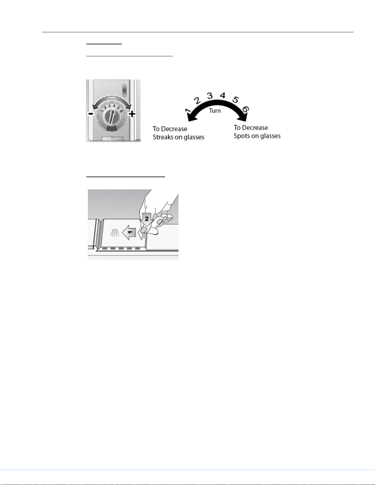
Dispenser
Adjusting rinse-aid dosage
The amount of rinse-aid can be adjusted at the dispenser.
Rinse-aid can be added by pouring it onto the arrow.
Closing dispenser doors
Slide cover fully left.
Push back end of the cover (onto the arrow) down
firmly until you hear a click.
702_58300000149896_ara_en_b
Page 12
COMPONENTS
IV. COMPONENTS
IVA. Dishwasher components
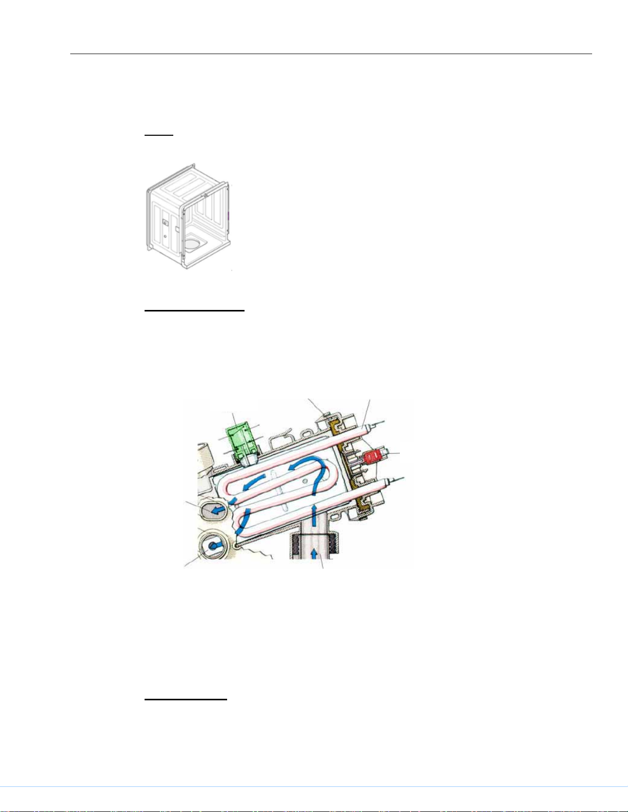
Tank
The tank, made of 304 stainless steel, isn’t available as a service part.
Heater Operation
Dishwashers use flow-through heaters instead of exposed elements, saving
space and allowing taller tanks holding larger dinner plates. Flow-through
heaters prevent dishware damage from exposed elements and allow water to
be continuously filtered and heated.
Heating element
Flow
switch
To upper
spray arm
To low
spray arm
er
Seal
NTC/Hi-limit
From circulation pump
Filtered water from the sump flows through the circulation pump into the flowthrough heater. All heaters are protected by a 185ºF Hi-limit (high temperature
cutout) and by a flow switch which prevents heaters from operating when no
water is flowing.
Heater ratings
120 VAC, 60 Hz, 1200 W
Heats water about 2ºF / minute
702_58300000149896_ara_en_b
Page 13
COMPONENTS
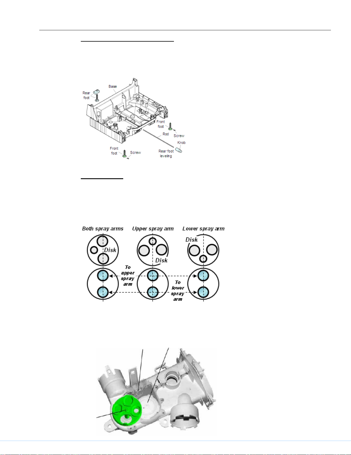
Leveling feet (front and rear)
The base is supported by three leveling feet, two front and one rear. The rear
leveling foot is adjusted from the front. Front feet have provisions for set screws
(in installation parts bag).
Water switch
Motor operated water switches are mounted underneath heater assemblies.
They consist of a motor-controlled disk with 3 holes which rotates and lines up
over two sump ports (upper / lower spray arms) to provide precise water control
to upper, lower or both spray arms.
Water switches are used to divert water to upper or lower spray arms. Separate
actuators aren’t needed.
European disk shown,
which is different
U.S. disk
Disk
702_58300000149896_ara_en_b
than
Microswitch
Cam
Page 14
COMPONENTS
Circulation pumps, heaters & sumps for water switch / non-water switch models
can’t be interchanged.
Circulation pumps
Bosch dishwashers use separate circulation and drain pumps to reduce overall
size, noise, vibration and energy consumption. This allows the use of tall tanks,
increasing overall space inside dishwashers where full-sized plates can be
placed in both upper and lower racks. Circulation pumps are suspended by
rubber straps to further reduce noise and vibration.
BLDC
Pump, motor and control come as one unit (# 665510). Speed changes as
needed for wash cycle and washability. Pump is isolated from motor, so there’s
no seal needed and no need to loosen or replace impellers.
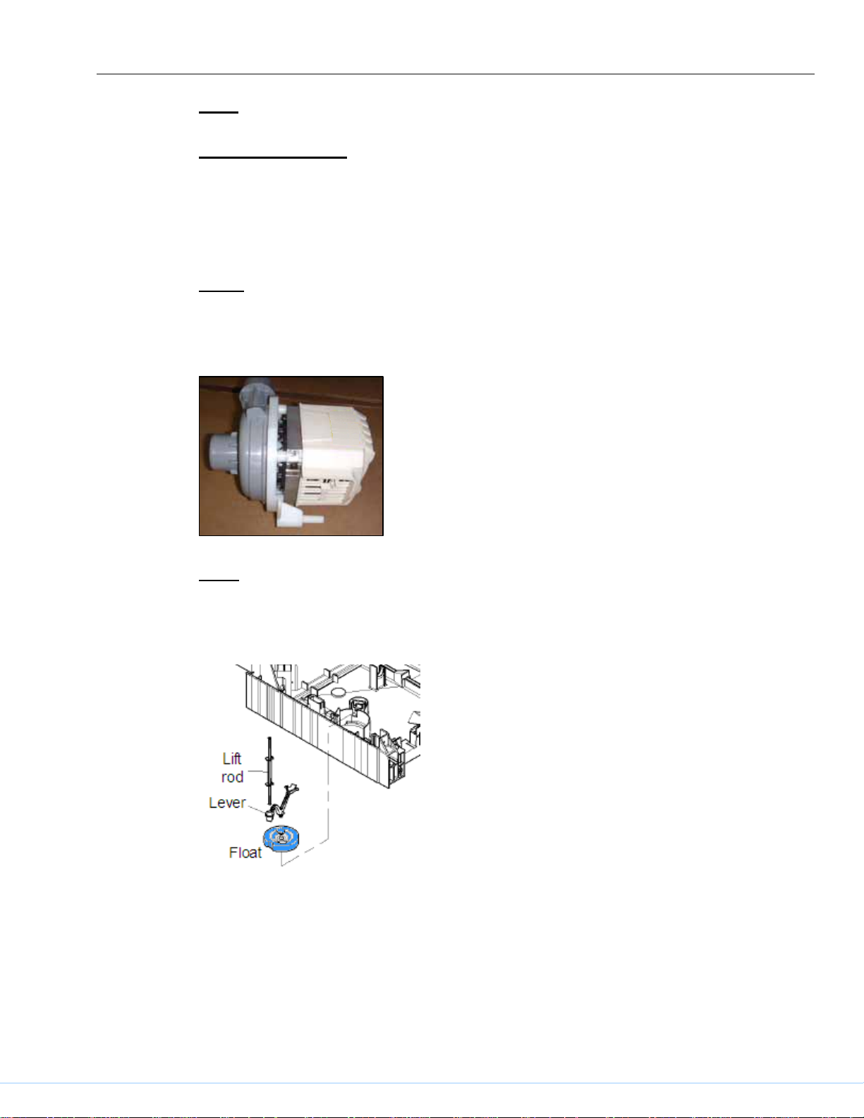
Float
The float is a safety device which starts the drain pump if there’s too much
water in the tank. It doesn’t act like a bilge pump (i.e. it won’t drain water from
the base).
If there’s water in the base or the float switch isn’t working, error code E5 is
possible.
702_58300000149896_ara_en_b
Page 15
COMPONENTS
Drain pump
Drain pumps are mounted to sumps in the front of dishwashers -- they’re easily
accessible from the front of dishwashers by removing toe kicks.
Pump specifications
Drain pump is rated 120V, 60 Hz, 35W, 0.85A.
Solving installation issues
Often improper installations, not drain pump issues, cause dishwashers to not
drain properly.
Must have drain hoses with high loops (min. 20” high) or drains with
air gaps.
Drain hoses are 6’ long and can be up to 10’ long.
Secure drain hoses to rear of dishwashers with non-metal bands.
Make sure drain hoses aren’t kinked.
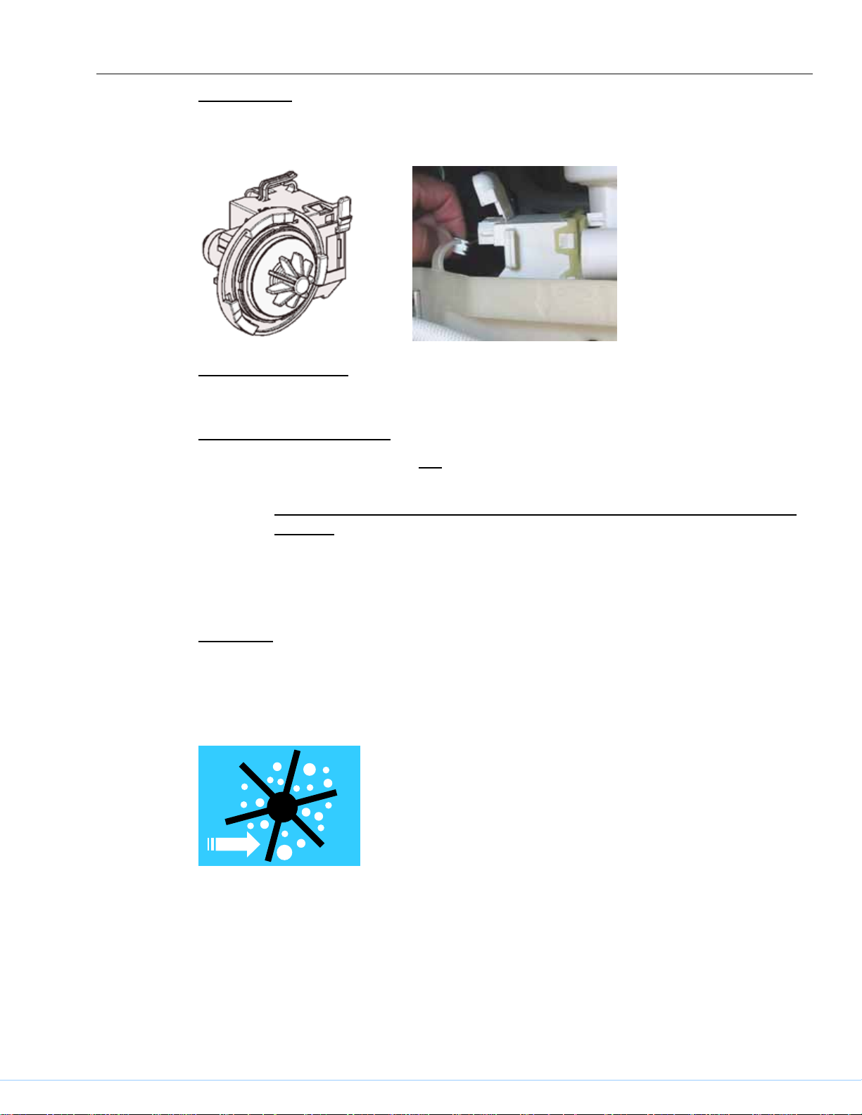
Cavitating
Cavitating may occur in any type of pump when impellers spin faster (from low
inlet or outlet pressure), creating air pockets around impellers. Cavitating
pumps can be noisy. Air gaps/high loops keep water contacting pump outlets,
preventing air pockets from forming.
702_58300000149896_ara_en_b
Page 16
COMPONENTS
Siphoning
Siphoning may occur in any type of drain pump when low water flow allows a
siphon (suction) to develop, pulling waste water back into the pump. Sump
check valves along with air gaps/high loops prevent siphons from being created.
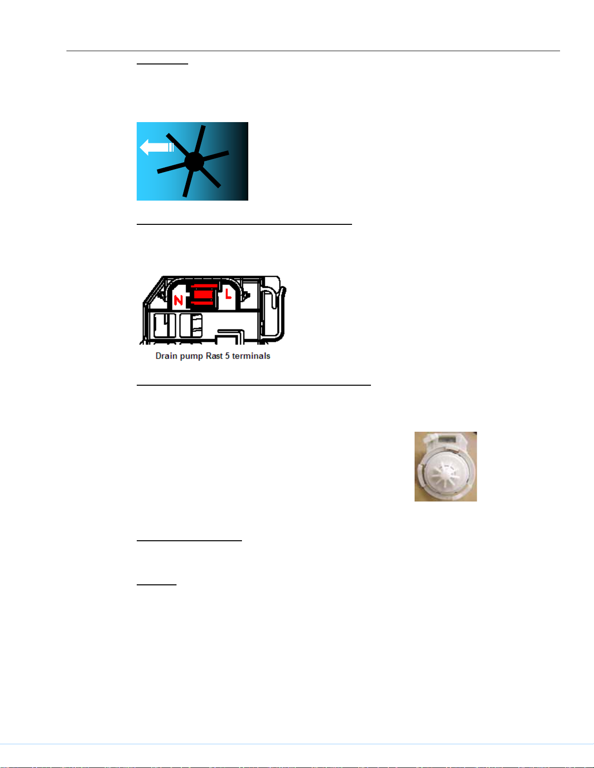
Terminal connections (Rast 5 connectors)
Rast 5 terminal connectors provide more positive connections than spade
terminals.
Johnson Tee installations (Washington State)
Drain pumps in installations with Johnson Tees (in Washington State) must use
stronger 4-vane pumps (607468).
Standard 9-vane drain pumps (642239) are quieter
and smoother than 4-vane pumps.
Water fill assembly
The water fill assembly is easily accessed from the left side.
Time fill
The time-fill water inlet system doesn’t have a diaphragm or water level switch.
Dishwasher controls allow water to fill for a specific time, relying on consistent
water flow through the water inlet valve to provide the correct water level.
702_58300000149896_ara_en_b
Page 17

COMPONENTS
Time-fill water valves look like pressure-fill valves, but have tight part tolerances
to insure consistent water levels. Time-fill valves can replace pressure-fill
valves, but pressure-fill valves can’t replace time-fill valves.
Flowmeter
Dishwashers use a flowmeter to provide more accurate water filling. An
impeller mounted magnet activates a reed switch.
Flowmeters are rated:
3.8 – 14 VDC, 1 ma
2.5 L / min, 0.5 – 10 bar
208 output pulses per liter
An arrow on the back of the flowmeter shows the
water flow direction.
702_58300000149896_ara_en_b
Page 18

COMPONENTS
Condensation tube
The condensation tube is crucial for condensation drying, which dries dishes
without a heating element in the bottom of the tank. Condensation tubes exit
the dishwasher at the right side of the tank.
Condensation tubes exit in the rear of dishwasher bases, allowing water vapor
to evaporate, and aren’t connected to customer drains.
Door spring
Using hinge slider (sliding pulley)
Hinge sliders (sliding hinge pulleys) are used instead of hinge pulleys. Instead
of rolling over rotating pulleys, door spring cords slide over pulley sliding
surfaces. The sliding surfaces provide better control than rotating pulleys (i.e.
reduces possibility of doors slamming closed or falling open).
702_58300000149896_ara_en_b
Page 19

COMPONENTS
618605 sliding hinge pulley kit consists of (2) sliding pulleys and (2) cords.
Hinge bushing
Hinge bushings hold doors in place (at hinges), using latches instead of
separate locks. Replacement door hinge levers contain hinge bushings.
Water inlet valve
Dishwashers use standard horizontal coil water inlet valves with (Rast 5)
connectors. The valve nestles in the left side of the base and is held into place
with two screws.
When reconnecting the water supply to the water valve, don’t overtighten the
elbow fitting.
Using Teflon tape on water fittings can help prevent leaking.
The water valve can be accessed without removing outer door or base
cover. However, removing them will provide easier access.
702_58300000149896_ara_en_b
Page 20

COMPONENTS
On/off switch
Door latch
The on/off switch turns the dishwasher on and off and is
crucial in resetting controls.
Contacts 5 & 6 reset the control. Whenever a control won’t
reset or won’t go into wash programs, check the on/off
switch and jumper. Replace switch and jumper if they’re
faulty.
Other than occasional misalignment, the only door latch
repairs will be replacing microswitches. Door latches are
held in place in console (frames) by tabs. It’s important
latches are properly seated in consoles and tabs are fully
inserted into latches.
Terminal block
Terminal blocks clearly show line (L), neutral (N) & ground (G) connections.
Dishwasher wire harnesses have spade terminals which connect to terminals
on the rear of the terminal block.
Terminal blocks can’t be installed in the field – the terminal box assy with
terminal block must be ordered. The terminal box assy assures the terminal
block is properly grounded to the terminal box.
Terminal box
All dishwashers have terminal boxes with covers and conduit exits.
702_58300000149896_ara_en_b
Page 21

COMPONENTS
Drain hose
Dishwashers use a two-hose (internal / external) drain hose system. A
customer (external) drain hose (during installation) is connected to the internal
drain hose, with the 90º elbow pointing toward the customer drain. The external
drain hose connects directly to the customer drain system without an adapter.
Dispenser
The dispenser is located near the top of the inner door and reliably dispenses
detergent and rinse-aid.
During each wash program, the wax motor opens twice, once to dispense
detergent and again to dispense rinse-aid. The wax motor opens the same -linkages open the detergent door & operate the rinse-aid dosage plunger.
Dispensers can have reed switches or optical rinse-aid sensors.
CAUTION: Inner door edges are sharp! Cover door edges and remove
dispenser carefully.
The white plastic linkage opens the detergent dispenser door, then cocks in
place to dispense rinse-aid when the wax motor operates again. After the 2nd
operation, the linkage resets for the next wash.
702_58300000149896_ara_en_b
Page 22

COMPONENTS
Optical rinse-aid sensors
Optical rinse-aid sensors determine if rinse-aid is present using a light beam
and sensor.
With rinse-aid present, the optical
receiver senses a diffused light
beam.
When rinse-aid has run out, the
optical receiver senses a strong
light beam.
: It’s possible for some clear rinse-aid brands to not diffuse light
TIP
adequately to show rinse-aid isn’t needed.
702_58300000149896_ara_en_b
Page 23

COMPONENTS
Aqua sensor
The aqua sensor is located behind the sump, to the left of the heater. It’s a twopiece assembly, with a small circuit board in a plastic housing). It senses water
cleanliness and allows the dishwasher control to remove pre-wash and/or prerinse cycles to save energy (~ 20% energy savings).
.
If water is clean enough, it will be kept for the wash cycle. If not, the aqua
sensor directs the dishwasher to add an additional pre-rinse or pre-wash cycle.
Dishwashers still operate adequately if aqua sensors fail. Customers will only
notice aqua sensors failing if they see their dishwashers running slightly longer
or their electric and water usage getting slightly higher.
Display and power modules
Dishwashers have two controls: a control module in the fascia (control) panel)
and a power module in the base on the right side. The power module controls
the circulation and drain pumps, while the control module controls the wash
programs.
Po
wer module
Control module
702_58300000149896_ara_en_b
Page 24

COMPONENTS
Sump parts
Sump
The sump contains a filter screen, large item (coarse) filter and micro filter.
The sump holds the drain pump cover and check valve.
Backflow (check) valve
The backflow (check) valve is located in the bottom of the sump near the
circulation pump inlet. It prevents waste water from entering the sump.
The valve material is clear, material doesn’t swell and provides improved
seating after many uses. Part # is 165262.
New valve
TIP: When washability issues arise, replace check valve along with other
repairs.
702_58300000149896_ara_en_b
Page 25

COMPONENTS
Spray arm feed tube
When water doesn’t spray from upper spray arms, check feed tube where it
enters the sump. Occasionally, the joint between the feed tube and its base
can loosen -- the entire feed tube must be replaced.
Info lights
Info lights shine a blue light onto floors, letting customers know their quiet
dishwashers are running. When dishwashers finish wash cycles, info lights shut
off.
702_58300000149896_ara_en_b
Page 26

COMPONENTS
Operation
Water circulation
The circulation pump pumps water from the sump through a triple filter system
to the heater. When water enters the heater, a flow switch determines water is
present and allows the heater to be activated. As water flows, it’s heated until it
reaches the pre-set temperature determined by the cycle. Once it leaves the
heater, it flows through the sump into the upper and lower spray arms.
Aqua
sensor
To upper
spray arm
To lower
spray arm
Backflow
valve
Drain pump
cover
Drain pump
NTC
Hi-li
Sump
mit
Impeller
Heating
element
Seal
Circulation
pump motor
The aqua sensor, drain pump, NTC, Hi-limit and backflow valve are near the
heater under the sump. The aqua sensor senses water cleanliness –
dishwashers add or subtract rinses as needed. The NTC senses water
temperature. The Hi-limit shuts off the heater if the water gets too hot. The
backflow valve prevents waste water from entering the dishwasher.
702_58300000149896_ara_en_b
Page 27

COMPONENTS
Serial label (warranty information)
The serial label, located on the right side of the inner door, contains the
dishwasher model, serial and index (KI) #’s.
Understanding the 17-digit serial #
This is detailed serial # is used by the factory for analysis of returned units. It’s
located in the bottom right corner of the label.
For example, for serial # 10 3 03 0081344 00011 5 (not shown on label above)
The first 2 #’s represent a factory code: 10 = dishwasher
The 3rd # represents the last digit of the year: 3 = 2003
The next 2 #’s represent the month: 03 = March
The next 7 #’s represent the model: 0081344 = SHY99A05UC
The next 5 #’s represent the unit made that month: 00011 = 11th SHY99A05UC
made that month
The last # represents a check digit = 5 in this case (is dependent on all
preceding #’s)
702_58300000149896_ara_en_b
Page 28

Repair
V. Repair
VA. Disassembly procedures
Use the following disassembly procedures to access parts such as fascia panels,
circulation pumps, heaters and controls.
To remove outer door
Tools needed: T20 Torx screwdriver.
1. Remove six T-20 Torx inner door screws below fascia panel -- three per
side (1).
2. Carefully pull bottom of outer door out from dishwasher until top door
tabs clear, then pull door down until it releases from dishwasher (2).
Take care to not scratch outer door.
TIP: 1-piece foam door guards don’t need to be removed from doors.
NOTE: Outer doors don’t need to be removed when dishwashers are flipped
upside-down or when fascia panels are removed, but can be if it makes
repairs easier.
To remove toe kick
Tools needed: Phillips screwdriver.
1. Remove two Phillips screws and tilt toe kick out from dishwasher.
702_58300000149896_ara_en_b
Page 29

Repair
To flip dishwasher upside-down
Tools needed: T20 Torx screwdriver, Phillips screwdriver and pliers.
1. Turn off water and electricity. Disconnect dishwasher mounting
brackets (1).
2. Remove toe kick by removing two Phillips screws and tilting toe kick
out from dishwasher (2).
3. Disconnect water line and electric supply (3).
4. Pull dishwasher out, place a pad or cardboard on the floor and carefully
flip the dishwasher upside-down (4).
5. Remove four base screws from front of dishwasher (5).
6. Remove two screws securing water valve to base. There’s no need to
disconnect valve wire harness or inlet hoses (6).
7. Pull wire harness connector from rear of terminal box (7).
8. Push latch on base-mounted control to disconnect it from base (8).
9. Remove both door springs from base (9).
10. Remove two tank screws from rear of dishwasher (10), disconnect both
rubber circulation pump supports (11) and carefully lift up base from
dishwasher (12).
702_58300000149896_ara_en_b
Page 30

Repair
Sump
Access to circulation pump,
heater and sump after base
has been removed.
Pump
Heater
To raise (block up) right side of tank
Tools needed: T20 Torx screwdriver and pliers.
1. Remove one T-20 Torx screw from both rear corners holding tank to base
(1) -- removing screw from both sides allows tank to be blocked upward.
2. Remove T-20 Torx screws from front right bottom corner holding tank to
base (2).
3. Remove right hinge cover (3) and release right door tension cord from
hinge (4).
4. Raise and block up tank as shown with strut onto base (5a), sliding a piece
of wood or other solid material between the tank and base to keep tank
from falling back onto base (5b).
702_58300000149896_ara_en_b
Page 31

Repair
VB. Water valves
Access the water valve from the front of the dishwasher base by removing the
toe kick.
To remove water valve
Tools needed: T20 Torx screwdriver & pliers.
1. Remove toe kick by removing two Phillips screws and tilting toe kick out
from dishwasher.
2. Remove base insulation (on models with insulation).
3. Move sump inlet hose away from water valve (without disconnecting it).
4. Disconnect wires from water valve, including ground wire.
5. Remove two T-20 Torx screws from water valve.
6. Pull valve out from dishwasher and disconnect water hose from rear of
valve. Remove any water from sump & base.
Connection hints:
Water connection 3/8” NPT female. Inlet water pressure range 5 - 120 psi
(0.3 – 8.27 bars).
When reconnecting the water supply to the water valve, don’t overtighten the
elbow fitting. On valves with vertical solenoids, the plastic can crack and
cause leaking if excessive force is used.
Using Teflon tape on water fittings can help prevent leaking.
The water valve can be accessed without removing outer door or base
cover. However, removing them will provide easier access.
VC. Circulation pumps
The circulation pump can be acc
essed by flipping the dishwasher upside-down.
Use the same process to access the heater.
For access to circulation pump
Tools needed: Phillips and T-20 Torx screwdriver, pliers.
1. Remove toe kick – see section VA.
2. Flip dishwasher upside-down & remove base – see section VA.
702_58300000149896_ara_en_b
Page 32

Repair
To remove complete pump
Tools needed: flat blade screwdriver.
1. Use a small flat blade screwdriver to carefully push in the pump housing
latch and rotate the pump clockwise (cw) to remove the pump (1).
2. Disconnect wire harness from pump motor after carefully noting
connections (2).
CAUTION: Don’t grab motor next to the capacitor to avoid jamming your
hand on the capacitor.
TIP: Pump motors can have a plastic (newer) or metal (older) housing.
Pumps with plastic motor housings cannot be removed by blocking up
the tank unless the capacitor is removed first (since the capacitor hits the
tank when the pump is rotated).
VD. Controls
Fascia panel mounted controls
Controls are easily removed from fascia panels by bending console tabs.
Tools needed: T-20 Torx & flat blade screwdrivers.
1. Remove fascia panel by removing T-20 Torx inner door screws.
2. Disconnect wire harnesses from module after noting connector locations.
3. Pry out metal console tabs holding module to console.
4. Carefully pry back plastic tabs, then slide module from console.
702_58300000149896_ara_en_b
Page 33

Repair
m CAUTION – 75% of all controls returned
for analysis check out OK. Most control
issues are due to loose connections.
Base mounted controls
Base mounted controls are located on the base between circulation pumps and
heaters, not behind fascia panels. So:
Dishwashers must be pulled out to change controls.
Dishwashers must be pulled out to measure voltages & resistances.
To access base-mounted controls
Tools needed: T-20 Torx screwdriver & pliers.
1. Remove outer door – see section VA.
2. Remove toe kick – see section VA.
3. Raise (block up) tank – see section VA.
To remove right side panel
Tools needed: T20 Torx screwdriver.
Dishwashers have a short side panel on the right side. Removing it provides
access to the circulation pump and heater and base-mounted control.
1. To remove right side plastic side panels, tilt top of panel and lift out.
Blocking the tank up makes it easier (a screwdriver is needed to remove
base screws first).
To remove base-mounted controls
1. Locate control, open control cover and disconnect wire harnesses from
module after noting connector locations
702_58300000149896_ara_en_b
.
Page 34

Repair
2. Push latch on back of control toward rear of dishwasher, then slide
control from base.
VE. Heaters
The heater, NTC and flow switch can be accessed or measured from the right
side of the dishwasher, but the heater and NTC can only be removed by
removing the base (by flipping the dishwasher upside-down) since the heater
fits tightly underneath the tank.
m CAUTION – 75% of all controls returned
for analysis check out OK. Most control
issues are due to loose connections.
For access to heaters & NTC’s
Tools needed: Phillips and T-20 Torx screwdriver, pliers.
1. Remove toe kick – see section VA.
2. Flip dishwasher upside-down & remove base – see section VA.
To remove heater, NTC & flow switch
1. Loosen pump - heater hose clamp and remove two T-20 Torx screws
holding heater assembly to sump.
2. Carefully pull heater from sump & pump. The heater comes as an
assembly with housing & gasket.
702_58300000149896_ara_en_b
Page 35

Repair
3. Note connections, remove NTC cover and disconnect wires from heater,
flow switch, NTC & Hi-Limit.
4. Push NTC latches and lift NTC from heater.
5. To remove flow switch, carefully pry housing away from switch (until tabs
clear switch), then snap switch out. Note flow switch can be removed
from right side without flipping dishwasher upside-down.
TIP: If needed, use rinse-aid to lubricate gaskets to make it easier to
assemble heater to sump and pump.
Softer bearing heaters
All heaters are “softer bearing” and have a gasket assembled to it (to connect to
the circulation pump) and use a hose clamp (172272 provided separately).
702_58300000149896_ara_en_b
Page 36

Repair
VF. 2-piece drain hose connection
Drain hoses come in two pieces, an external (customer) drain hose and an
internal drain hose. The 90º elbow of the external hose is connected to the
outlet of the internal hose (pointing toward the drain) and is held in place by a
hose clamp.
To remove the internal drain hose, remove a white plastic hose lock and pull the
hose from the water level control.
VG. Drain pumps
To access pump, disconnect inlet hose and pump harness. To remove pump,
(1) pull latch (on circular collar), (2) rotate pump clockwise (cw) ~ 1/8 turn and
(3) pull out pump. To install new pump, insert @ 2:00 position & rotate
counterclockwise (ccw).
VH. Dispensers
Dispens
ers can be accessed from the front by removing the outer door.
Tools needed: Small flat blade and T-20 Torx screwdrivers.
To remove dispensers
1. Remove outer door -- section VA.
2. Disconnect wire harnesses from dispenser. Don’t remove the cable tie
keeping the harness away from the dispenser. It must be replaced if it’s
removed.
3. Using a small flat blade screwdriver, push the six inner door tabs holding
the dispenser.
4. Carefully push the dispenser in toward the inside of the inner door.
702_58300000149896_ara_en_b
Page 37

Repair
m
dispenser carefully.
VI. Door latches
Other than occasional misalignment, the only door latch repairs will be replacing
microswitches.
To remove door latches
CAUTION: Inner door edges are sharp! Cover door edges and remove
1. Remove fascia panel -- section VD.
2. Locate door latch in console and bend out console metal tabs to allow
latch removal.
3. Remove door latch from console.
4. If door latch has a microswitch cover, disconnect wire harness and
remove microswitch & cover.
5. Remove microswitch from door latch.
HINT: Make sure plastic latch tabs are aligned & metal console tabs are
bent back completely during reassembly.
702_58300000149896_ara_en_b
Page 38

Repair
Misaligned door latches
Occasionally integrated dishwasher door latches can be misaligned, causing
doors to not close properly or dishwashers to run with doors open (when latches
don’t reset). Follow these steps to realign door latches.
1. Insert latch tabs into frame.
2. Bend tabs down into latch.
3. Reset latch to open position.
HINT: Make sure latch tabs are seated, all fascia frame
(console) tabs are bent completely, door strikes are
aligned with latches and door latches get reset.
702_58300000149896_ara_en_b
Page 39

Fault Diagnostics
VI. Fault Diagnostics
VIA. Customer service test program
Entering customer service test program
Controls contain codes for factory tests, customer service test program,
dishwasher configuration and error codes. Consult test programs and error
codes for your dishwasher before using the codes from this manual.
1. Open the door.
2. While pushing (and holding) any two wash cycle buttons, turn the
dishwasher on with the on/off switch. While the buttons are held, the
model coding will show (e.g. “C2”, “C5”, etc.). After releasing the
buttons, LED “B” will be lit, LED “C” will flash and “P0” will display,
confirming you’re in the special programs menu.
3. To select the test program, push button “B” repeatedly until “P1” is
displayed or until LED “C” is lit.
4. Push button “C” to start the program -- LED “C” will blink. Close the door
after pushing button “C”). The steps will show on the digital display (e.g."S:01") -- push button “B” to skip a step.
Stored error codes will show on the digital display and LED’s (see Error code
displays on the next page).
The test program can only be stopped / reset by pushing the on/off button – it
can’t be done by turning off the power.
702_58300000149896_ara_en_b
Page 40

Fault Diagnostics
Error code displays
Error codes can be found using the customer service test program.
1. Open the door.
2. While pushing (and holding) any two wash cycle buttons, turn the
3. Push button “C” to start the Error Code program (instead of pushing “B”
4. The last 8 error codes are stored. Repeatedly pushing and releasing
dishwasher on with the on/off switch. While the buttons are held, the
model coding will show (e.g. “C2”, “C5”, etc.). After releasing the
buttons, LED “B” will be lit and LED “C” will flash and “P0” will display,
confirming you’re in the special programs menu.
to select the test program). As button “C” is held, the earliest cycle with
an error code is displayed (“00”) – when button “C” is released, the error
code is displayed. If there’s more than one error code, the code with the
highest priority is displayed (see chart below).
button “C” scrolls from the oldest cycle with an error code (“00”) to the
latest (“07”).
Dishwashers can show the following error codes.
Error code E5 is safety float water level reached. If this error code occurs,
check the float and float switch, check if water is in the base and check if the
water inlet valve has re-seated after closing.
Clearing error codes
To clear error codes, run the customer service test program.
702_58300000149896_ara_en_b
Page 41

Fault Diagnostics
Viewing customer service program
Open the door to (push the buttons to) enter the test program. Close the door
to run the test program.
Push button “B” to skip a step.
Symbol
AS_KAL_IR = Calibrate aqua sensor
F = Water fill
FWW = Soft water fill
H = Heating
UK = Bottom rack
OK = Top rack
P = Drain pump
PA = Pause
SP = Intermittent pump
U = Circulate
VF = Pre-fill
WP = Alternate pumping
WWP = Water switch positioning
WS = Alternate rinsing
ZK = Dispense rinse aid
ZR = Dispense deterge
nt
702_58300000149896_ara_en_b
Page 42

Fault Diagnostics
VIB. Troubleshooting
Dishwasher troubleshooting
Fault Steps to determine failure Failure Resolution
No power
1. Check wiring connections to
dishwasher and if supply voltage is
≈ 120V.
2. Check if wiring connections at
interference suppressor (RFI filter)
are properly seated.
3. Disconnect power and check
resistance between following
terminals
on/off switch to close it.
A. Black wires of interference
B. On/off switch “L1” terminals 4
C. “N” white wire and control
D. White wires of interference
. For all measurements, push
suppressor (RFI filter) “L1”
terminals.
(black wire) and 3 (gray-black
wire to control).
connector 6-4 yellow wire (with
door closed
suppressor “N” terminals.
).
1. If dishwasher connections are
improper, replace cord / wiring with
minimum 14 awg (rated 75˚C). If
voltage isn’t 120V, check for open
circuit breakers or fuses.
2. If connectors aren’t seated, reseat
them. If connectors are damaged,
replace wire harness.
3. Replace parts as follows:
A. If resistance is ≈ 0 Ω go to step
3B. If not, replace interference
suppressor (RFI filter).
B. If resistance is ≈ 0 Ω, go to step
3C. If not, replace on/off switch.
C. If resistance is ≈ 0 Ω, control is
shorted and should be replaced.
If not, go to step 3D.
D. If resistance is ≈ 0 Ω, replace
on/off switch. If not, replace
interference suppressor.
No heat,
heating
error or
NTC error
1. Run customer service test program
and check if spray arms are turning.
2. Measure resistance between the
NTC orange wires.
3. Check resistance between red wire
from control to heater thermostat
and white or white-red (“N”) wire
from flow (pressure switch). Before
measuring, close the flow
(pressure) microswitch by removing
it from heater housing and pushing
the button.
4. Check resistance between
thermostat terminals and between
heating element terminals (r1).
5. With pressure switch removed,
check if heater pressure plate
moves freely.
1. If spray arms aren’t turning, see
2. If resistance isn’t within the values
3. If resistance is not
4. If thermostat is open (∞ Ω), replace it.
5. If pressure plate moves freely,
Circulation Pump Not Running.
below, check NTC connections. If
connections are OK, replace NTC.
77º F (25ºC) 45840 Ω
22º F (50ºC) 16542 Ω
140º F (60ºC) 11067 Ω
≈ 12 Ω, go to step
4. If resistance is ≈ 12 Ω, go to step 5.
If heating element is open (∞ Ω),
replace heater. If thermostat and
heating element aren’t open, replace
pressure switch.
replace control. If not, replace heater.
702_58300000149896_ara_en_b
Page 43

Fault Diagnostics
Fault Steps to determine failure Failure Resolution
Dispenser
not
operating
or rinse aid
not being
dispensed
Will not
drain
1. Check if detergent dispenser cover
is jammed.
2. Check dispenser harness
connections to rinse aid dispenser,
dispenser actuator (A2) and control.
3. Run customer service test program
with outer door removed and check
if actuator operates. It should
operate once to open detergent
dispenser door and a second time
to dispense rinse aid.
4. Check resistance between
dispenser actuator terminals.
1. Check if house drain line is clogged.
2. Check that drain hose is no longer
than 150” and includes a 20” high
loop.
3. Check if garbage disposal plug is
removed.
4. Check if drain hose is clogged or
pinched.
5. Check if drain pump impeller is
blocked.
6. Run customer service test program
and measure drain pump current
while drain pump is activated.
7. Check wiring connections at
terminal 1 of float switch (white
wire), drain motor and control.
8. Measure drain pump resistance
(between “N” and gray wire from
drain pump to control).
1. Free jammed cover (by opening and
2. If connectors aren’t seated properly,
3. If actuator operates, but doesn’t open
4. If resistance is not between 2050 -
1. Unclog drain and check operation.
2. Shorten or replace drain hose and
3. Remove garbage disposal plug.
4. Unclog or replace drain hose.
5. Unblock impeller and check
6. If current is ≈ 0.68 A and water does
7. If connectors aren’t seated properly,
8. If the resistance is between 23 - 28 Ω,
closing it) or replace damaged cover.
reseat them. If connectors are
damaged, replace wire harness.
detergent dispenser cover or release
rinse aid, replace dispenser linkages.
2250 Ω, replace dispenser actuator. If
not, replace control.
add 20” high loop.
operation.
not drain, replace drain pump.
reseat them. If connectors are
damaged, replace wire harness.
replace control. If not, replace drain
pump.
Circulation
pump not
running or
dishes still
dirty
702_58300000149896_ara_en_b
1. Run customer service test program
and check if dishwasher is filling
with enough water.
2. Check if water switch failed (i.e.
check if only one rack is dirty).
3. Run customer service test program
and check incoming current to
dishwasher while the heater is on.
4. Check for clogged spray arms or
filters.
5. Check if circulation pump rotates
freely with power disconnected.
6. Check that connections to
circulation pump motor, door switch
(e1) and control are seated properly
and aren’t damaged.
7. Measure door switch resistance
(between door switch terminals 1
and 2) with dishwasher door closed.
1. If not filling, see Will Not Fill.
2. Replace heater assembly (with water
switch).
3. If current draw is ≈ 11A, go to step 4.
If not, go to step 5.
4. Clear any obstructions from filter and
spray arms.
5. If pump doesn’t rotate freely, check
for obstructions in pump housing. If
there are no obstructions, replace
pump.
6. If connectors aren’t properly seated,
reseat them. If connectors are
damaged, replace wire harness.
7. If the resistance is approximately 0 Ω,
replace circulation pump. If not,
replace door switch.
Page 44

Fault Diagnostics
Fault Steps to determine failure Failure Resolution
Will not fill
or does not
fill with
enough
water
1. Check if water supply is turned on
and water pressure is between 15145 psi (1-10 bar).
2. Check if water inlet screen is
blocked.
3. Check if float switch (e6) has
activated or water is in dishwasher
base.
4. Run customer service test program
and measure voltage between
water inlet valve terminals.
5. Check that orange wire connections
to flow meter are seated properly
and not damaged.
6. Check that connections to float
switch (e6) and control are seated
properly and not damaged.
7. Measure float switch (e6) resistance
between terminals 4 & 1 (by
measuring between gray wire (“L”
terminal) of drain pump (m3) and
terminal 3 of on/off switch (a1)).
8. Measure water inlet valve
resistance (between violet wires).
1. Turn water supply completely on and
adjust to proper water pressure.
2. Clean out water line and screen.
3. Check for leaks and drain water from
the base to disengage the float
switch. If water won’t drain from
dishwasher tub, see Will Not Drain.
4. If voltage is not
If the voltage is ≈ 120V, replace water
inlet valve.
5. If connectors aren’t properly seated,
reseat them. If properly seated,
replace flow meter or harness.
6. If connectors aren’t properly seated,
reseat them. If connectors are
damaged, replace wire harness.
7. If resistance is ≈ 0 Ω, the float switch
is stuck closed and should be
replaced. If resistance is not ≈ 0 Ω, go
to step 8.
8. If resistance is ≈ 950 Ω, replace
control.
≈ 120V, go to step 5.
Heater diagnosing
Test programs heat the water to 150ºF at ~ 2ºF / minute. To save time, don't
run the entire test – when water circulates and the heater is on, measure the
incoming current to the dishwasher. If the current is ~ 11A, the heater is OK. If
the current is ~ 1.5 – 2A, the control or heater could be faulty.
At the control or heater, measure the voltage between the large red heater wire
and a chassis ground or the dw neutral (WHRD on/off switch or flow switch
wire). If the voltage is 120 VAC, the control is OK. If the voltage is 0, the heater
relay has failed – replace the control.
702_58300000149896_ara_en_b
Page 45

Fault Diagnostics
To check the heater, turn off the dishwasher, block up the tank and check the
resistance of each part of the heater as follows.
TIP: Current can be measured through the red heater wire at the control or
heater (~ 9.5A). There can be more than one red wire, so check the wiring
diagram to select the heater wire.
Heater ~ 11 Ω
Hi-Limit ~ .3 Ω
Flow switch ~ .4Ω. A spring loaded plunger closes it when
water is flowing, so you must remove the microswitch from
the heater and close its contacts to measure the resistance.
NOTE: Open door to run test program.
Making NTC and HiLimit measurements
Flow
switch
Controls timing out and showing “1”
Occasionally dishwashers can run for hours, not finish washing & show a “1” in
the display. This means the module has timed out due to an unidentified
heating problem -- all heating related parts must be checked until the problem is
found.
Heating system checklist if controls time out:
Check control module heater relay & solder joints.
Check wire harness & terminals (to control and heater). Controls have been
replaced when the problem was loose connections.
Check heater resistance (~ 11).
Check flow switch (~ 0.4). If flow switch is OK & water doesn’t flow, check
circulation pump.
702_58300000149896_ara_en_b
Page 46

Fault Diagnostics
Check NTC (~ 55k @72ºF) and Hi-Limit. See NTC resistance chart
(below).
IMPORTANT: Whenever a “1” shows in the control display, reset the control
after fixing the heating problem by running the dishwasher. The module resets
after the 1st run.
NTC resistance chart
Where to
measure NTC
resistances
702_58300000149896_ara_en_b
Page 47

Fault Diagnostics
Water Leaking Past Doors
Water seldom leaks out of bottom of dishwasher doors. Usually it’s a customer
or installation issue. Occasionally air pockets (from standing water in loops) or
kinks in condensation tubes block condensation tubes and cause leaking.
Pressure builds in tanks, blowing water past lower door seals (usually at start of
cycles). Draining condensation tubes and straightening out kinks solves these
occasional problems.
Checklist if water leaks past doors:
Make sure condensation tubes are inserted into bases, not connected to
drains or air gaps.
Clear and drain condensation tubes, including debris in bases.
Re-drill wood doors to make them square.
Straighten kinks in condensation tubes.
Educate customer on oversudsing (from too much detergent/rinse-aid or
overly soft water).
Level dishwasher before attaching under-counter brackets.
Replace damaged door seals, including replacements cut too short.
Refill lower racks overfilled with dishes.
Move flexible cutting boards to left side of dishwasher.
Cosmetic / Customer Use / Installation Issues
Control codes during Cancel - Reset -- Customers have pushed / held
Cancel - Reset buttons while turning dw’s on and entered control coding
selection or customer service test programs showing codes such as E0, P0,
P1, C1, P2, etc.
Not cleaning or locking sump filters.
Smelly dishwashers -- Often occurs from filters not being cleaned, drain
hose high loops missing or drain gases being present. If all else is OK, then
problem can be preservative not purged from tank door gasket.
Doors leaking or not latching -- Usually an installation issue (dishwasher
brackets installed before dishwashers are leveled front to back, tanks &
doors out of square, wooden doors not drilled accurately). Can be blockage
in condensation tubes or condensation tubes connected to drain hose air
gaps.
Inner door damage -- From upper rack during improper shipping and
handling (dishwashers clamped on wrong sides or dropped).
Doors hit toe kicks -- Toe kick installation issue.
Junction boxes -- Comes from wires not being connected correctly during
installation.
702_58300000149896_ara_en_b
Page 48

Fault Diagnostics
Dispensers -- Customers using too much detergent, not using rinse-aid &
not knowing how to close the door.
Drain hoses not installed properly -- Often no air gap or high loop +
pinched hoses -- causes poor draining & smelly dishwashers. Most drain
pumps are mistakenly replaced for drain hose installation issues.
Outer doors -- Most are dinged during shipment.
Damaged water valves -- Primarily from fittings being overtightened. A
damaged valve can allow some water onto kitchen floors.
Customer self-help diagnosing
Dishwashers may occasionally exhibit problems unrelated to a dishwasher
failure. The following fixes can be made by customers without calling for repair.
Dishes do not dry -- The rinse agent dispenser may be empty. Check the
rinse-aid dispenser and refill it if necessary. Dishware drying can be
accelerated and enhanced by opening the dishwasher door slightly and
propping it open with the top rack.
Indicator light(s) do not come on -- A fuse may have blown or a circuit
breaker tripped. Check the fuse or circuit breaker at your fuse box/breaker
box and replace the fuse or reset the breaker if necessary.
Dishwasher does not start -- The dishwasher door may not be properly
shut. Make certain the dishwasher door is shut and latched.
Dishwasher runs a long time -- If the dishwasher completes the cycle, but
the run time seems exceptionally long, it may be due to cold incoming water.
Before starting the dishwasher, open the hot water faucet at the sink nearest
the dishwasher. Run the water until it runs hot, then turn off the water and
start the dishwasher.
Machine cycle does not advance to rinse -- The water supply line may be
shut off. Check the water supply valve and open it if it’s shut.
White spots left on dishes -- More rinse agent is needed.
Water not pumped from dishwasher –
o Make certain the drain hose isn’t kinked, clogged, or improperly
installed. Make sure the drain hose is at least 20 inches above the
floor.
o Make certain the dishwasher filter system and kitchen sink drain
aren’t clogged. You may need a plumber rather than a serviceman for
the dishwasher. If an air gap is installed at sink, it may be clogged.
Detergent dispenser cover will not shut – The cover may not have been
shut correctly or a cycle was not finished and should’ve been cancelled.
Streaks on glassware -- Too much rinse agent is being dispensed.
Rattling noises -- Utensils may not be properly arranged.
Suds in dishwasher – The customer may have used the wrong type of
dishwashing detergent. Use only automatic dishwasher detergents.
702_58300000149896_ara_en_b
Page 49

Technical Specifications
Unsatisfactory washing results
o Incorrect amount of detergent.
o Utensils incorrectly arranged or rack overloaded.
o Spray arm rotation blocked by utensils.
o Spray arm nozzles need cleaning.
o Filters not properly fitted into position.
o Unsuitable cycle selected.
VII. Technical Specifications
Dishwasher ratings – Dishwashers are rated 120VAC, 60 Hz, 15A, 1450W (max.).
Maximum amp draw when heaters running ~ 11A.
Heater ratings
Noise level – Dependent on model, from 44 db – 56 dB.
Circulation pump ratings (BLDC motor) – 120VAC, 60 Hz, 100W (~ .13 HP), 3-phase.
Drain pump ratings – 110 - 127 VAC, 60 Hz, 35W, .84A, 17Ω (9-vane)
Water inlet pressure range – From 5 – 120 psi (.3 – 8.27 bar).
Circulation pump flow rate – Approximately 60 liters/minute (~ 15.85 gallons/minute)
at a pressure of 420 mbar (6.1 psi).
Drain pump flow rate – Approximately 10 liters/minute (~ 2.64 gallons/minute) at a
delivery height (head) of .9m (2.95’).
Water inlet valve flow rate – Approximately 2 liters/minute (~ .5 gallons/minute).
– 120VAC, 1200W, flow-through, heats water ~ 2ºF / minute.
702_58300000149896_ara_en_b
Page 50

Wiring Diagrams
VIII. Wiring Diagrams
702_58300000149896_ara_en_b
Page 51

Wiring Diagrams
702_58300000149896_ara_en_b
 Loading...