

Page 1
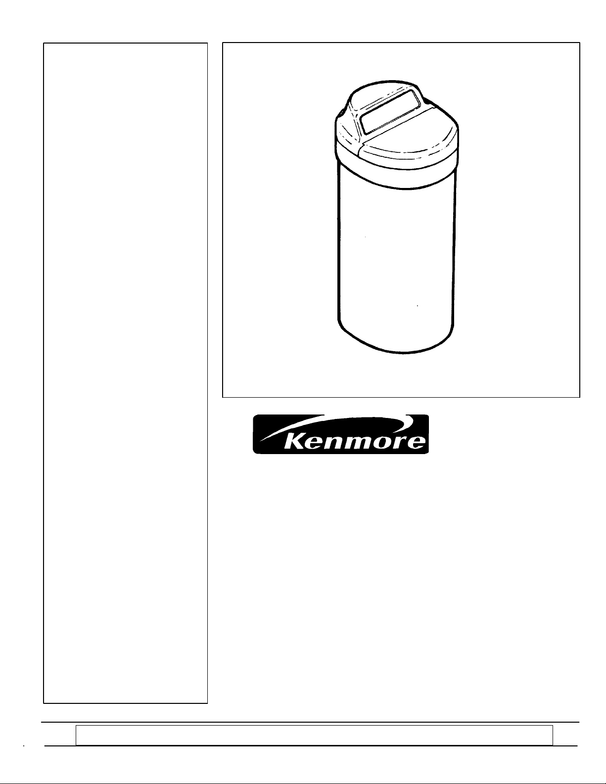
OWNER’S
MANUAL
MODEL NO.
625.348321
Caution:
Read and Follow
All Safety Rules and
Operating Instructions
Before First Use of
This Product.
Solid State Water Softener
z Warranty
z Start Up / Setting Timer
If you have questions when
installing, operating or maintaining your softener, and
when setting the timer, call
this toll---free number...
1---800---426---9345
SAVE THIS MANUAL
Sears, Roebuck and Co., Hoffman Estates, IL 60179 USA
PRINTED IN U.S.A.
z How It Works
z Care Of / Troubleshooting
z Specifications
z Repair Parts
Use plastic bag and tie provided, to hang manuals nearby
the softener for future reference.
Page 2
WARRANTY
SEARS RESIDENTIAL WATER SOFTENER
FULL ONE YEAR WARRANTY ON WA TER SOFTENER
Foroneyearfromthedateofpurchase, whenthiswatersoftenerisinstalledandmaintained
in accordance with our instructions, Sears will repair, free of charge, defects in material or
workmanship in this water softener.
FULL TEN YEAR WARRANTY AGAINST LEAKS
For ten years from the date of purchase, Sears will furnish and install a new current model
water softener tank or salt storage drum, free of charge, if either the tank or drum develop
a leak.
TO OBTAIN WARRANTY SERVICE, SIMPLY CONTACT THE NEAREST SEARS SERVICE
CENTERTHROUGHOUTTHEUNITEDSTATES.Thiswarrantyappliesonlywhilethisproduct is in use in the United States.
Thiswarrantygivesyouspecificlegalrights,andyoumayhaveotherrightswhichvaryfrom
state to state.
Sears, Roebuck and Co., D/817 WA, Hoffman Estates, IL 60179
Ifyou want yourwater softener professionallyinstalled,talk to yourSears Salesman. Hewillarrange
for a prompt, quality installation by Sears Authorized Installers.
SEARS INSTALLATION POLICY
All installation labor arranged by Sears shall be
performed in a neat, workmanlike manner in
accordance with generally accepted trade practices. Further,all installations shall comply with
all local laws, codes, regulations, and ordinances.Customershallalsobe protected,during
installation, by insurance relating to Property
Damage, Workman’s Compensation and Public
In addition to any warranty extended to you on
the Sears merchandiseinvolved, which warranty becomes effective the date the merchandiseis
installed, should the workmanship of any Sears
arranged installation prove faulty within one
year, Sears will, upon notice from you, cause
suchfaultstobecorrectedatnoadditionalcostto
you.
SEARS INSTALLATION WARRANTY
Liability.
FACTS AND FIGURES TO KEEP
Fill in the blanks below and keep this book in a safe
place so you always have these facts.
Water Softener Model No.†
Serial Number
Date Installed
Water Hardness Grains Per Gallon
Iron Content Parts Per Million
*pH Taste And/Or Odor
Water Pressure Pounds/Square Inch
Water Flow Rate Gallons Per Minute
† The model number is on the rating decal, located
on the rim, under the salt hole cover.
2
Page 3

TABLE OF CONTENTS
PAGE
NO.
SECTION 1 SOFTENER START UP
A. SAFETY GUIDES 4
B. CHECK LIST OF STEP-B Y-STEP GUIDES TO INSTALL 5
C. PROGRAM THE TIMER 6
D. SANITIZING THE WATER SOFTENER 7
E. FILL THE STORAGE TANK WITH SALT 8
SECTION 2 HOW YOUR WATER SOFTENER WORKS
A. FACE PLATE TIMER FEATURES 9-10
B. SOFT WATER SERVICE AND REGENERATION 11-13
SECTION 3 CARE OF YOUR SOFTENER
A. SALT: REFILLING STORAGE TANK, SALT BRIDGE 14
B. KEEPING THE WATER SOFTENER CLEAN 15
C. KEEP THE SOF TENER FROM FREEZING 16
D. HELPFUL HINTS CHECKLIST 17
SECTION 4 OTHER THINGS TO KNOW
A. HOW TO “FINE-TUNE” YOUR WATER SOFTENER 18-20
B. DIMENSIONS/SPECIFICATIONS 21
SECTION 5 SERVICE TECH INFORMATION
A. ELECTRICAL CONNECTIONS 22
B. REGENERATION CYCLE TIMES 23
C. TROUBLESHOOTING 24-26
D. ROTARY VALVE SERVICE 27
E. WATER FLOW THROUGH THE SOFTENER VALVE 28-30
SECTION 6 REPAIR PARTS 32-35
3
Page 4

SECTION 1
1A. SAFETY GUIDES
WATER SOFTENER START- UP
Y Read all steps, guides and rules carefully before installing and using your new water softener.
Followall steps exactly to correctly install. Failure
to follow them could cause personal injury or
property damage.Readingthisbookwillalsohelp
you to get all of the benefits from your water soft ener.
Y Your water softener will remove hardness minerals and “clear water” iron from water, up to the
limits shown on page 21. It will not remove other
types of iron, acids, tastes and odors, etc. It will
not purify polluted water or make it safe to drink.
Y Protect the softener and piping from freezing.
Damage from freezing voids the softener warranty. See page 16.
CAUTIONS
PLEASE READ AND COMPLY WITH THE FOLLOWING GUIDES TO PREVENT DAMAGE TO
THE SOFTENER OR OTHER PROPERTY,
PERSONAL INJURY, OR POSSIBLE FATAL
SHOCK.
Y THIS SOFTENER WORKS ON 24 VOLTS
ONLY. BE SURE TOUSE THE TRANSFORMER
INCLUDED, AND PLUG IT INTO A 120V OUT LET.
Y Unplug the transformer right away if the
power cable should become damaged or
frayed. Make repairs before plugging back
into the power outlet.
Y Always unplug the softener from electrical
power before removing outer valve covers.
4
Page 5
SECTION 1
1B. CHECK LIST OF ALL STEP-BY-STEP GUIDES TO INSTALL
Refer to the Installation Manual, part no.
7159931, for step-by-step guides.
To be sure you have done all the steps to install
the softener, read the following list. Page numbers referred to are in the Installation Manual.
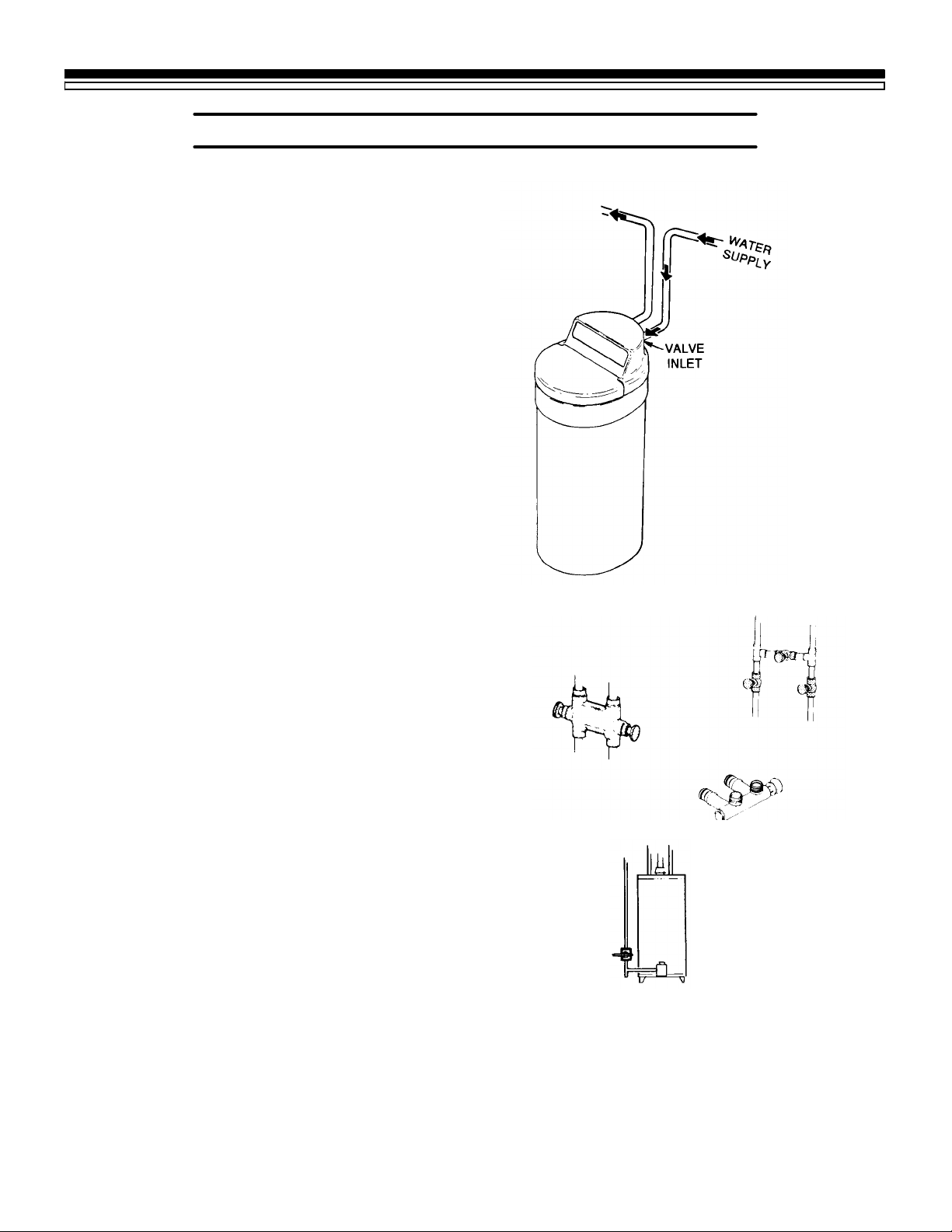
n Is the house water flow going INTO the soft-
ener valve INLET? Trace piping to be sure.
See pages 10 and 11.
n Is the plumbing bypassvalve(or3valves)set
forSERVICE?Bypassvalve(s)shouldalways
remain in soft water service position. Position in “bypass” only if needed for softener
repairs. See page 18.
WATER SOFTENER START- UP
n Is the valve drain hose connected the right
way, and without sharp bends or kinks that
couldstoporreducewaterflow?See page16.
n Is the softener power cable connected to the
transformer, and is the transformer plugged
into an inside, 120V-60Hz electrical outlet?
See page 20.
n Be sure to restart the water heater. See page
20.
3--valve
brass
Bypass
Valves
plastic
Water
Heater
Note, for installations in the State of Massachusetts:
Plumbing codes of Massachusetts shall be adhered to.
Consult with your licensed plumber.
5
Page 6
SECTION 1
1C. PROGRAM THE TIMER
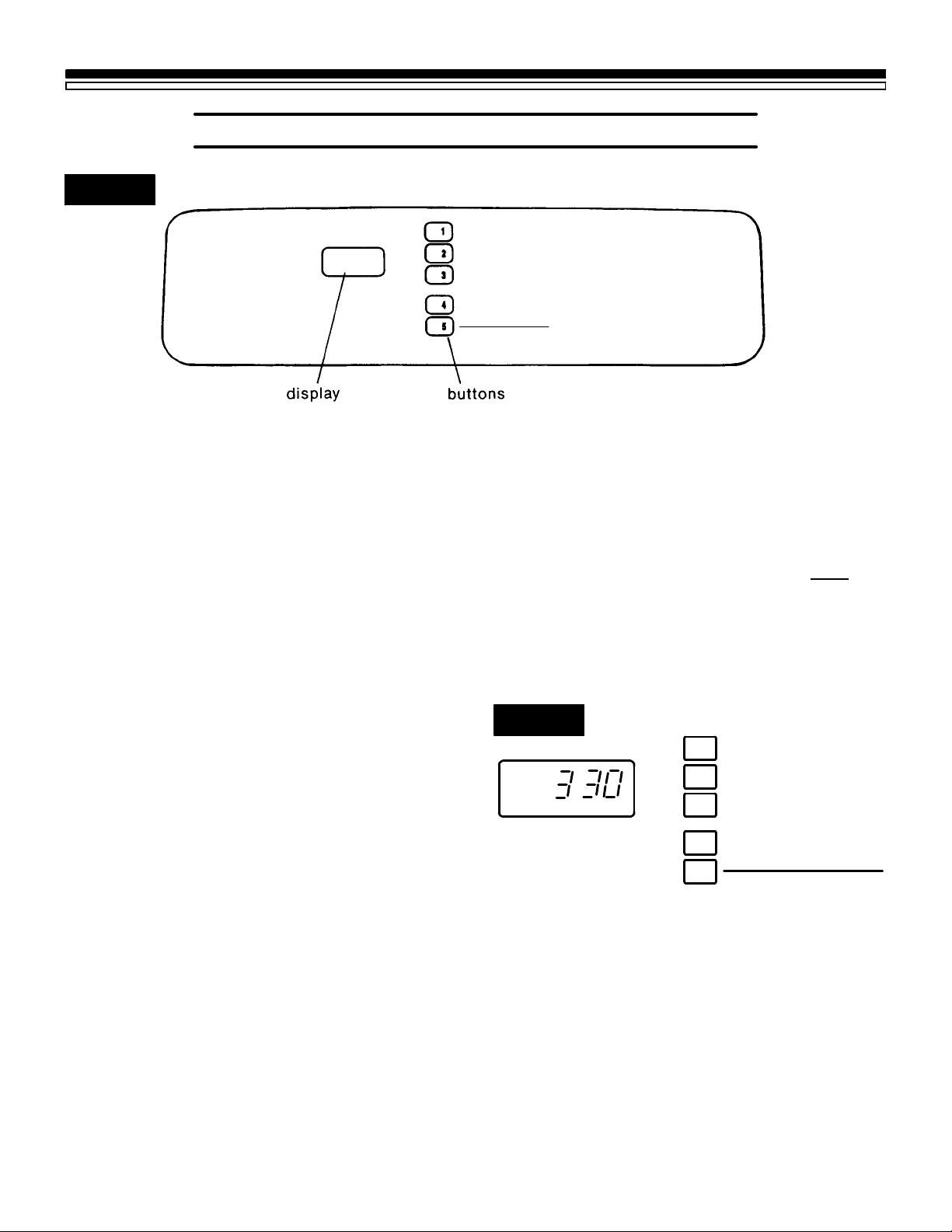
FIG. 1
WATER SOFTENER START- UP
PRESENT TIME
RECHARGE TIME
RECHARGE DAY
SET THE TIMER
Whenthetransformerispluggedintotheelectrical outlet, 12:00 AM, SUnday began to flash in
thetime display.Set thetime of day andpresent
day of week as follows:
A. SET TIME OF DAY
1. Press the PRESENT TIME AND DAY button
¡ once. The hour display continues to flash.
2. Press the SET/CLEAR button £ until the
presenthour of the day shows in the display.
Be sure AM for morning hours, or PM forafternoon and evening hours shows.
NOTE:
Press SET/CLEAR and quickly release to move
the hour display ahead 1 at a time to the correct
hour. Or, hold the SET/CLEAR button to move
the display ahead 2 hours each second, to the
correct hour.
3. Press button ¡ once to steady the hour dis-
play, and minutes begin to flash. Repeat step
A2 to set the correct minutes.
4. Press button ¡ again to steady the minute
display (day will begin flashing). Figure 2
shows the timer set at 3:30 PM. See step B to
set the present day.
SET / CLEAR
ON / OFF
VACATION
HOLD RECHARGE NOW
Solid State Water Softener
B. SET PRESENT DAY OF WEEK
1. Press the SET/CLEAR button £ to set the
present day of the week in the display.
NOTE:
Press SET/CLEAR and quickly release to move
the day display 1 at a time. Or, hold the
SET/CLEAR button to move the day display
ahead 2 days each second.
2. Press the PRESENT TIME AND DAY button
¡again to steadytheentiredisplay.Figure2
shows the timer set at TUesday.
FIG. 2
PRESENT TIME AND DAY
1
RECHARGE TIME
2
RECHARGE DAY
3
SET / CLEAR
4
ON / OFF VACATION
5
HOLD
RECHARGE NOW
TU
.
.
PM
EXAMPLE: This drawing
shows 3:30 PM as the
present time of day, and
TUesday is the current
day of the week.
No other settings are needed after installing
yourwatersoftener. Thesoftenerisfactory set to
regenerate every Monday, Wednesday and Saturday(beginning at2:00AM).Formostfamilies,
this gives enough soft water for their needs.
However, if you want the softener to regenerateata differenttime,or ondifferentdays, orto
set for the most efficiency, see “Fine-Tuning
Your Water Softener,” page 18.
SEE PAGE 9 FOR OTHER TIMER CONTROLS AND FEATURES.
6
Page 7
SECTION 1
1D. SANITIZING THE WATER SOFTENER
WATER SOFTENER START- UP
Care is taken at the factory to keep your water
softener clean and sanitary. Materials used to
make the softener will not infect or contaminate
yourwatersupply,andwillnotcause bacteria to
form or grow. However, during shipping, storage, installing and operating, bacteria could get
into the softener. For this reason, sanitizing as
follows is suggested¡ when installing.
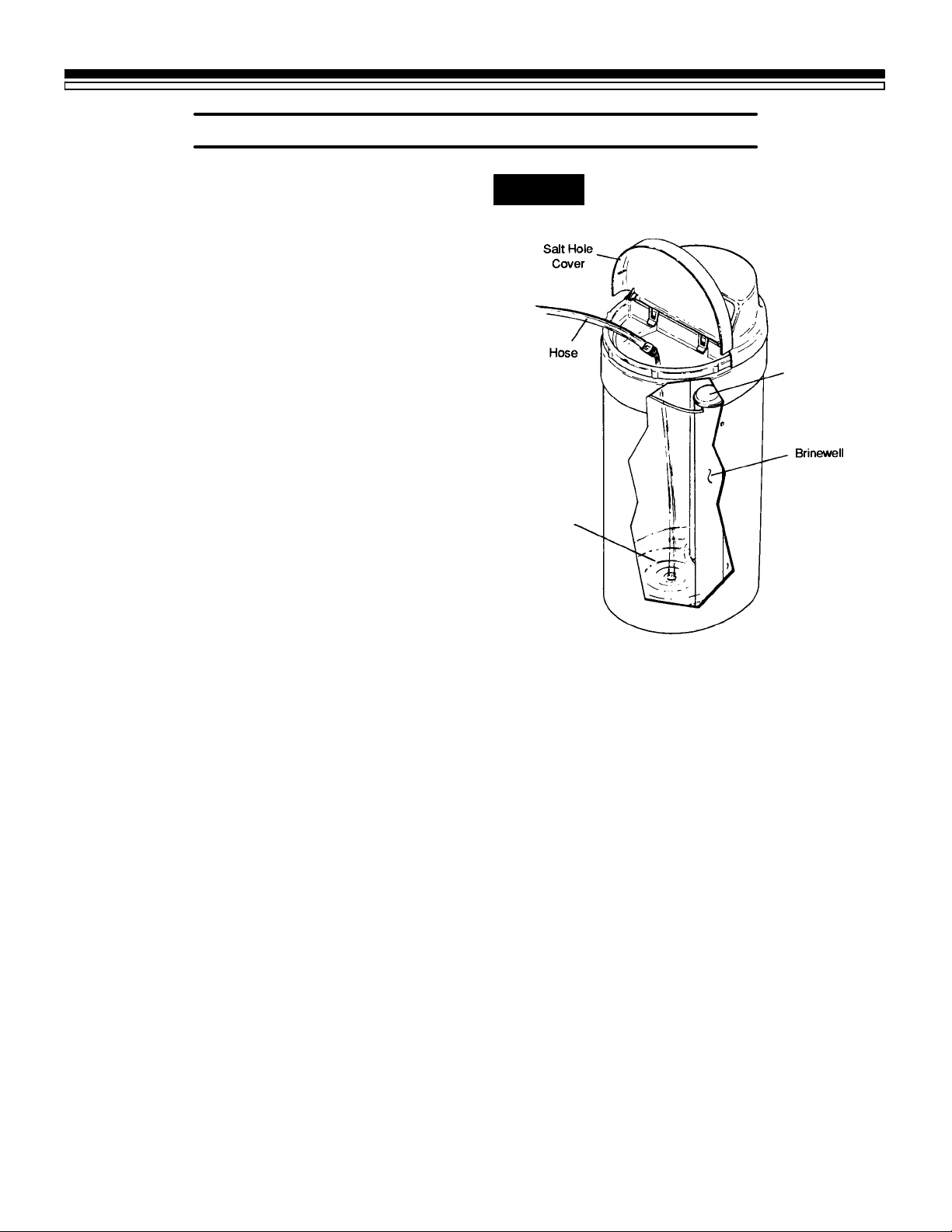
1. Lift the salt hole cover and use a pail or hose
to fill the salt storage tank with at least 3
gallons of water.
2. Remove the brinewell cover (FIG. 3) and
pour about 3/4 ounce of common 5.25%
household bleach (Clorox, Linco, BoPeep,
White Sail, Eagle, etc.) in the softener brinewell.
3. PresstheON/OFF-HOLDbuttonand holdfor
3 seconds to start a recharge. This first re-
charge does several things.
— It draws the bleach into and through the
softener to sanitize it.
FIG. 3
Brinewell
Cover
(remove and add
about 3/4 oz. bleach)
Water,
About 3 Gallons
— Itfillsthesalttanktothewaterlevelneed-
ed.
— It gets all the air out of the resin tank.
— Itmakes the resinbed (seepage 11)ready
for service.
NOTES:
This recharge takes about 2 hours.
You can sanitize the softener with or without salt in the storage tank.
¡ Recommended by the Water Quality Association. On
some water supplies, the water softener may need
periodicdisinfecting.Sanitize withor withoutsaltin the
storage tank.
7
Page 8
SECTION 1
1E. FILL THE STORAGE TANK WITH SALT
WATER SOFTENER START- UP
Brine(saltdissolvedinwater)isneeded for each
and every regeneration. The water for making
brine is metered into the salt storage tank by the
softener. However,you must keep the tankfilled
with salt.
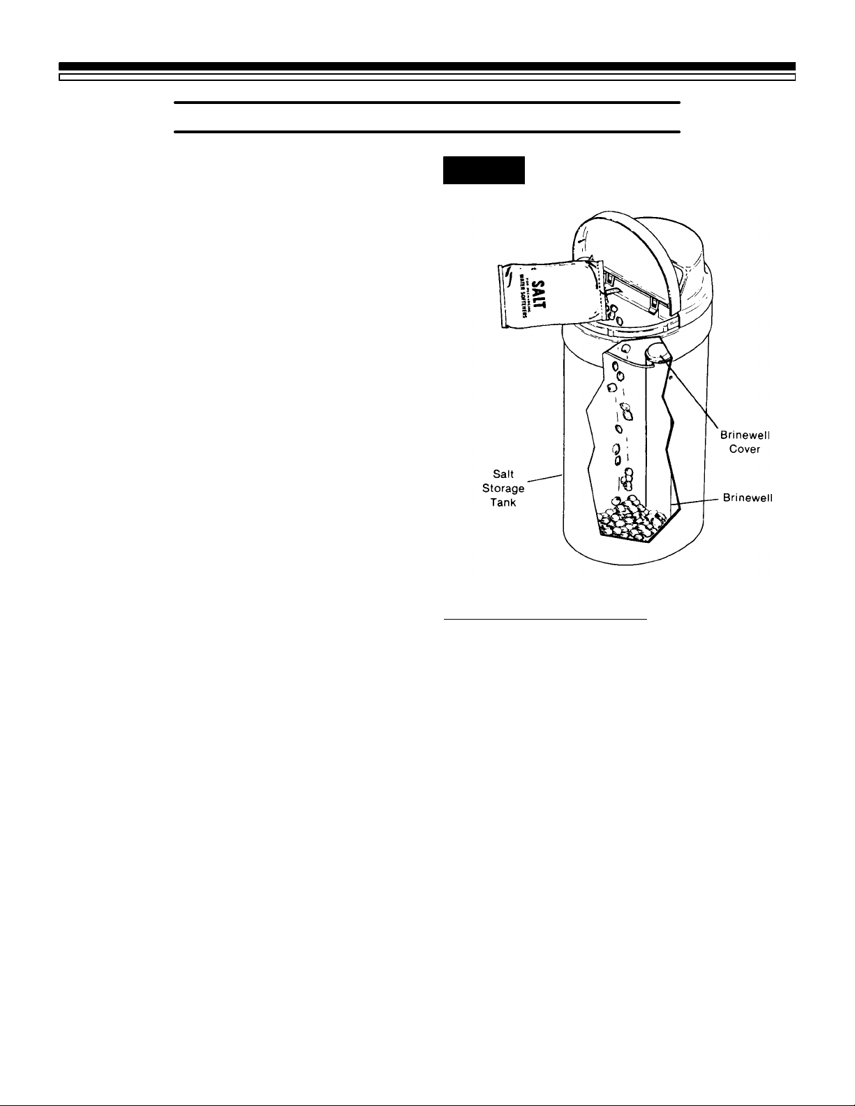
Fill the tank with NUGGET or PELLET water
softener salt. DO NOT use rock salts, as they
have dirt and sediments that will stop the
softener from working.
Before filling, be sure the brinewell cover is in
place on the top of the brinewell. Salt storage
capacity is shown on page 21.
NOTES:
In humid areas, it is best to fill the storage tank
half-full,and to refillitmoreoften.Saltbridging
(seepage14)occurs moreoften when conditions
are humid.
WA TER SOFTENING SALT WITH IRON REMOVING ADDITIVES — Some salts have an
additive to help the softener handle iron in the
water supply. Although this additive may help
to keep the softener resin clean, it may also
release corrosive fumes that will weaken and
shorten the life of some softener parts.
FIG. 4
SODIUM INFORMATION: Water softeners using sodium chloride for regeneration add sodium to the water. Persons who are on sodium
restricted diets should consider the added sodium as part of their overall sodium intake.
For example, if your water supply is 15 grains
hard, you would have to drink 3 quarts of
softened water to consume 335 milligrams of
sodium. That is equivalent to eating 2-1/2 slices
of white bread.
Personswho are concerned abouttheir drinking
water should consider a Sears Drinking Water
System that will remove or reduce in excess of
90% of the sodium and other drinking water
contaminants.
YOU HAVE NOW FINISHED THE WATER SOFTENER START UP. AFTER THE SANITIZING RECHARGE, ON PAGE 7, THE SOFTENER WILL BE GIVING YOU SOFT WATER.
8
Page 9
SECTION 2
2A. FACE PLATE TIMER FEATURES
HOW YOUR WATER SOFTENER WORKS
RECHARGE NOW — If you have guests visiting, or other times when you use more water
than usual, you could begin to run out of soft
water. If the softener is not scheduled toregenerate for another day or 2, you would get hard
water until then. If this happens, or you think it
might happen, press and hold in the HOLD-RECHARGE NOW button ¤ for 3 seconds until
RCHG shows. RCHG will flash in the display
during the regeneration, which lasts under 2
hours.
NOTE:
Avoid using HOT water while the softener
regenerates, because bypass hard water will
refill the water heater (see “Automatic Bypass,”
page 13).
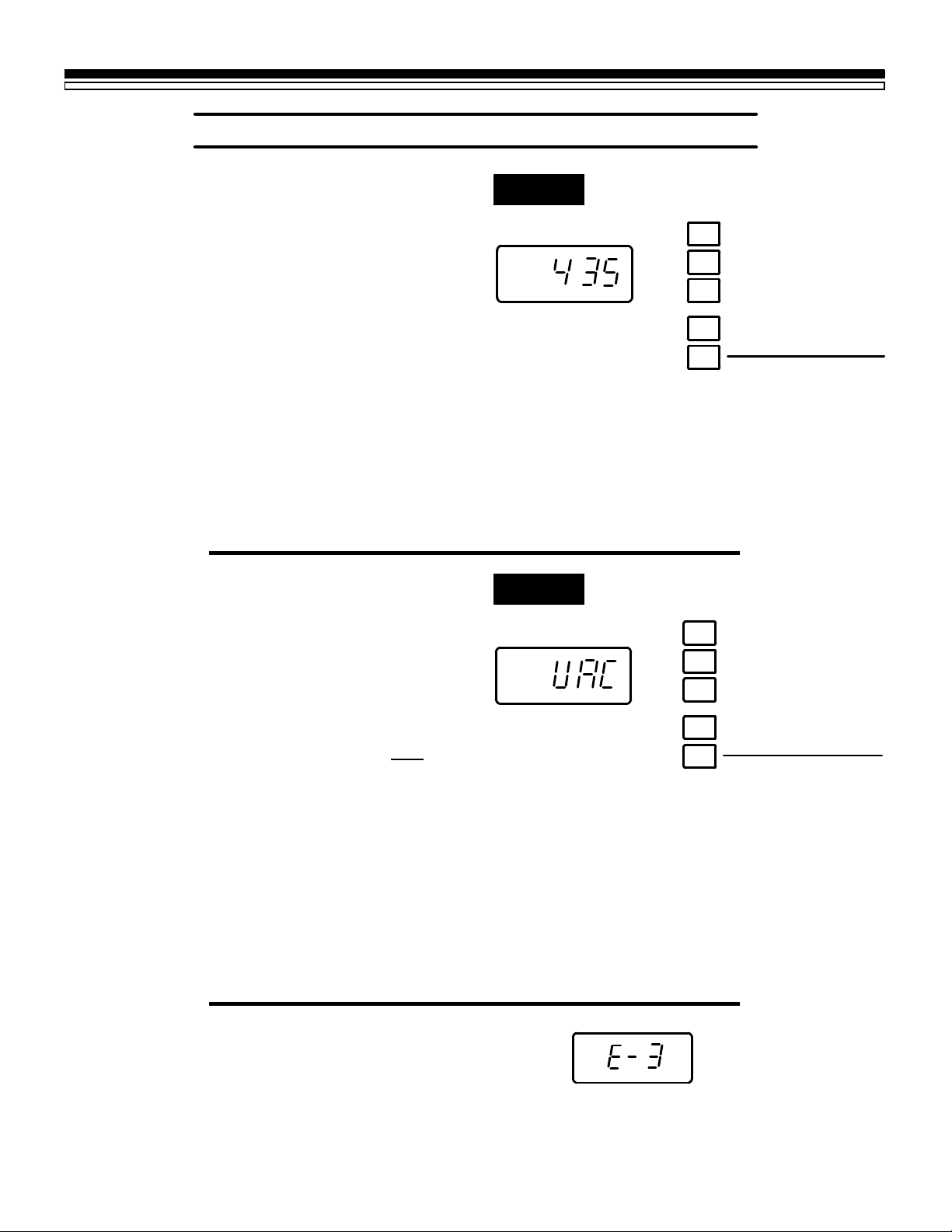
VACA TION— Thedayyouleaveonvacation,or
other long absence, press (do not hold in) the
ON/OFF VACATION button ¤. VAC begins to
flash in the display (FIG. 6). The timer will keep
time, but the softener will not regenerate to
waste water and salt.
FIG. 5
PM
RCHG
FIG. 6
PRESENT TIME AND DAY
1
RECHARGE TIME
.
.
2
RECHARGE DAY
3
SET / CLEAR
4
ON / OFF VACATION
5
HOLD
PRESENT TIME AND DAY
1
RECHARGE TIME
2
RECHARGE DAY
3
RECHARGE NOW
NOTE:
Whie in VACATION, the softener will go
througharegenerationif the RECHARGE NOW
feature is used (see above).
To shut off the water supply to the softener, use
the plumbing bypass valve(s), FIG. 16, page 21.
WHEN YOU RETURN, press the VACATION,
buttonagaintoreturnthesoftenertoservice,and
thecorrecttimeofdayinthedisplay.Remember
to do this or the softener will not regenerate
and you will soon have hard water.
ERRORCODE— Anerrorcodecouldappearin
the face plate display if a problem occurs in the
softener electronics. If you see an error code
insteadofthepresenttimeofday,please callyou
local Sears Service Department for service.
SET / CLEAR
4
ON / OFF VACATION
5
HOLD
RECHARGE NOW
Continued
9
Page 10

SECTION 2
2A. FACE PLATE TIMER FEATURES
HOW YOUR WATER SOFTENER WORKS
TIMER “POWER -OUTAGE MEMORY” — If
electrical power to the timer goes off, the
“memory” built into timer circuitry keeps all
settings for 6 hours (minimum) or more. The
display is blank and the softener will not
regenerate.Whenelectricalpowercomeson,1of
2 things will happen.
1. The present time of day will show, meaning
the timer memory has kept all settings.
NOTE:
Ifthesoftenerwasinaregenerationwhenpower
was lost, it will now finish the cycle.
2. The display will show a time, but it will be
flashing.Thetimermemory did not keepthe
timesettings and theymust be reset(page6).
The flashing display is to remind you to reset
the timer.
NOTE:
When power comes on, the flashing display
returns to a time of 12:00 AM Sunday, then
begins to keep time again. If you do not reset all
timesettings, the softener will regenerate3 days
each week. However, regeneration will most
likely be on the wrong days and at the wrong
time.
Ifthesoftenerwasinaregenerationwhenpower
wentoff,thevalvewill returnto service position
without finishing the regenerationcycle. If your
water tastes salty:
-- use RECHARGE NOW (see page 9) to start
another regeneration, or
-- open1ormoresoftwaterfaucetsandallowto
run until the salt taste is gone.
10
Page 11
SECTION 2
2B. SOFT WATER SERVICE AND REGENERATION
HOW YOUR WATER SOFTENER WORKS
SERVICE
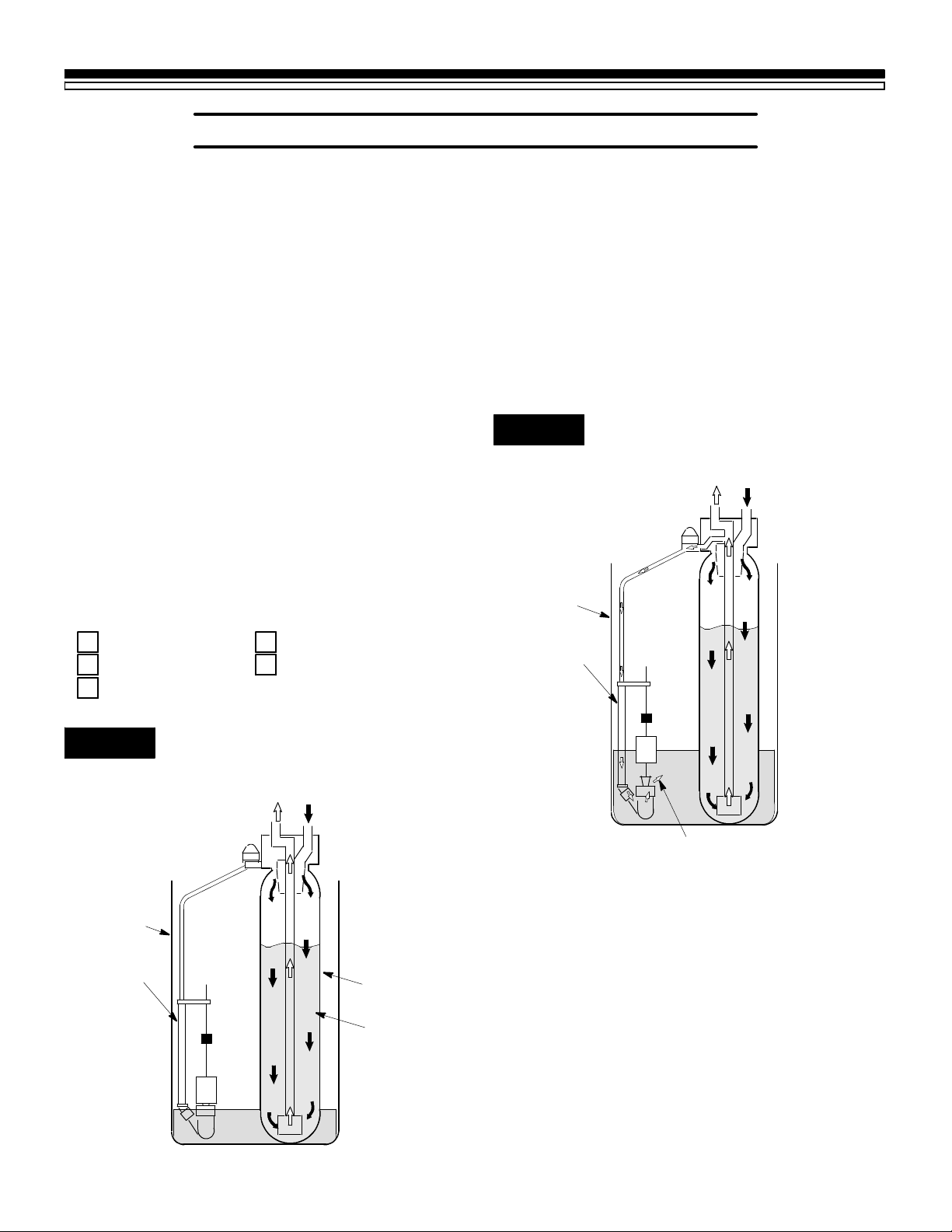
When the softener is giving you soft water, it is
called “Service”. During service, hard water
comes from the house main water pipe into the
softener. Inside the softener resin tank is a bed
madeupofthousandsoftiny,plastic resinbeads
(FIG. 7). As hard water passes through the bed,
each bead attracts and holds the hardness
minerals. This is called ion-exchanging. It is
much like a magnet attracting and holding
metals. Water without the hardness minerals
(softwater)flowsoutofthesoftenerandintothe
house soft water pipes.
After a period of time, the resin beads become
coated with hardnessminerals and they have to
be cleaned. This cleaning is called recharge, or
regeneration.
Regeneration is started at about 2:00 a.m. (factory setting) by the timer. It takes place in 5 stages
or cycles. These are:
REGENERATION
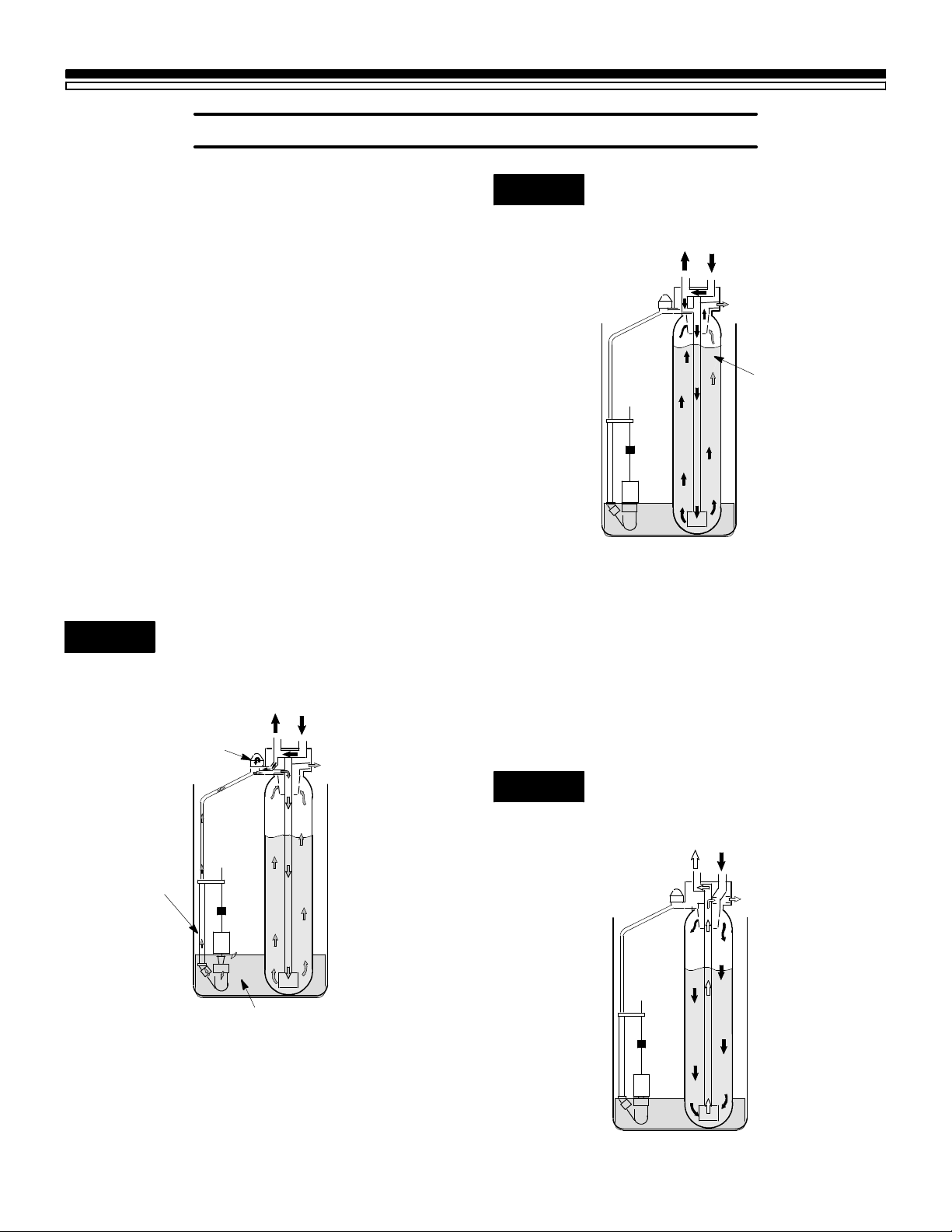
¡FILL: Salt, dissolved in water, is called brine.
Brine is needed to clean the hardness minerals
from the resin beads. To make the brine, soft
water flows into the salt storage area during the
fill cycle as shown in FIG. 8.
The length of the fill cycle is factory set to
providesofteningcapacityforanaveragefamily.
You can reset this time when “fine-tuning” the
water softener, pages 18 through 20.
FIG. 8 WATER FLOW THROUGH THE
SOFTENER IN FILL
soft water
OUT
salt storage
tank
hard water
IN
FILL
1
BRINING
2
3
BRINE RINSE
BACKWASH
4
5
FAST RINSE
FIG. 7 WATER FLOW THROUGH THE
SOFTENER IN SERVICE
soft water
OUT
salt storage
tank (salt
not shown)
brine valve
hard water
IN
resin tank
resin bed
brine valve
fill water
11
Page 12
SECTION 2
2B. SOFT WATER SERVICE AND REGENERATION
HOW YOUR WATER SOFTENER WORKS
©BRINING: During brining,the brine ismoved
from the salt storage area, into the resin tank.
Inside the resin tank, brine cleans hardness
minerals from the resin beads and they are
discharged out the drain. How much brine is
needed to clean the resin depends on:
-- the amount of resin in the softener.
-- how fast the brine goes through the bed.
The nozzle and venturi (FIG. 9) makes the
suctionto take brinefromthesalttankand put it
into the resin tank. It keeps the brine flow down
to a very slow rate to get the best resin cleaning
with the least salt.
¢BRINE RINSE: After all of the brine goes into
the resin tank, the brine valve closes. Water
keeps flowing the same way it did during
brining, except the brine flow has stopped.
Hardness minerals and brine flush from the
resin tank to the drain.
FIG. 9 WATER FLOW THROUGH THE
SOFTENER IN BRINING AND
BRINE RINSE
hard water
bypass OUT
nozzle &
venturi
hard water
IN
drain
FIG. 10 WATER FLOW THROUGH THE
SOFTENER IN BACKWASH
hard water
bypass OUT
hard water
IN
drain
resin bed lifted
and expanded
¤FAST RINSE: Backwash is followed by a fast
flow of water down through the resin tank. The
fastflowpackstheresinbedandgetsitreadyfor
return to service (FIG. 11).
After fast rinse, the softener returns to service.
Hard water goes into the resin tank where the
resinbed again takes out the hardness minerals.
Soft water goes to the house soft water pipes.
FIG. 11 WATER FLOW THROUGH THE
SOFTENER IN FAST RINSE
brine valve
brine
£BACKWASH: During backwash, water flows
UP through the resin tank (FIG. 10) at a fast rate
to flush iron minerals, dirt and sediments from
the bed and to the drain. The bed lifts and
expands for good cleaning.
12
soft water
OUT
hard water
IN
drain
Page 13

SECTION 2
2B. SOFT WATER SERVICE AND REGENERATION
HOW YOUR WATER SOFTENER WORKS
AUTOMA TIC BYPASS
During the brining, brine rinse and backwash
cycles of regeneration, HARD water goes
through the softener valve and to the house
pipes. If a faucet is opened, hard water is there
for your needs. However, you should not use
HOTwater,if possible, becausethe water heater
willrefillwith hard water.Thesoftenerregeneratesfrom2:00AMtoabout4:00AM,(youcanset
anytime), a time when not much water is used.
If you get up early in the morning and you can
hear the softener regenerating, change the time
setting.Set the rechargetimeto12:00AM or 1:00
AM (page 18). Then regeneration will start and
endthatmuchearlierandyourwaterheaterwill
not refill with hard water if a hot faucet is
opened.
13
Page 14
SECTION 3
3A. SALT¼REFILLING STORAGE TANK/BREAKING A SALT BRIDGE
CARE OF YOUR SOFTENER
WHEN TO REFILL WITH SALT: Check the salt
level a few weeks after you install the softener
and every week after that. Refill when the
storage tank is about 1/3 full. Never let the
softener use all the salt before refilling. Without
salt, you will soon have hard water.
PLEASE SEE PAGE 8 FOR SALT FILLING DIRECTIONS.
SALT BRIDGE
Sometimes, a hard crust or salt bridge forms in
thesalt storage tank.It is usuallycaused by high
humidityorthewrongkindofsalt.Whenthesalt
bridges, an empty space forms between the
waterandsalt.Then,saltwillnotdissolve(melt)
in the water to make brine. Without brine, the
resinbed does not regenerate and you will have
hard water.
IMPORTANT:
You will have a loss in softening capacity and
may get partly hard water if less than 10 inches
of salt is in the storage tank.
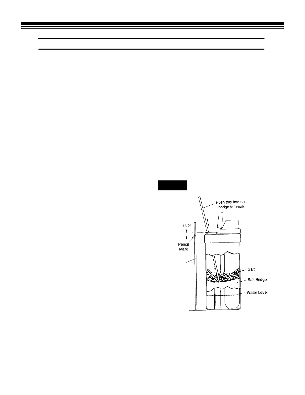
FIG. 12 A SALT BRIDGE
Ifthe storage tankis full ofsalt,itis hardto tell if
youhaveasaltbridge.Saltislooseontop,butthe
bridge is under it. The following is the best way
to check for a salt bridge.
Salt should be loose all the way to the bottom of
thetank.Holdabroomhandle,orliketool,upto
the softener as shown in FIG. 12. Make a pencil
markon the handle,1, or 2,below the top height
of the rim. Then,carefully push it straight down
into the salt. If a hard object is felt before the
pencil mark gets to the top of the tank, it’s most
likely a salt bridge. Carefully push into the
bridge in a few places to break it. Do not try to
break the salt bridge by pounding on the
outside of the salt tank. You may damage it.
Ifthe wrong kind of salt made the bridge, take it
out. Then fill the tank with nugget or pellet salt
only.
Broom Handle
14
Page 15
SECTION 3
3B. KEEPING THE WATER SOFTENER CLEAN
CARE OF YOUR SOFTENER
COVERS
To keep your new Kenmore water softener
looking nice, apply a coat of paste wax and
repeat once a year. When dusty, wipe it with a
damp cloth to keep it sparkling.
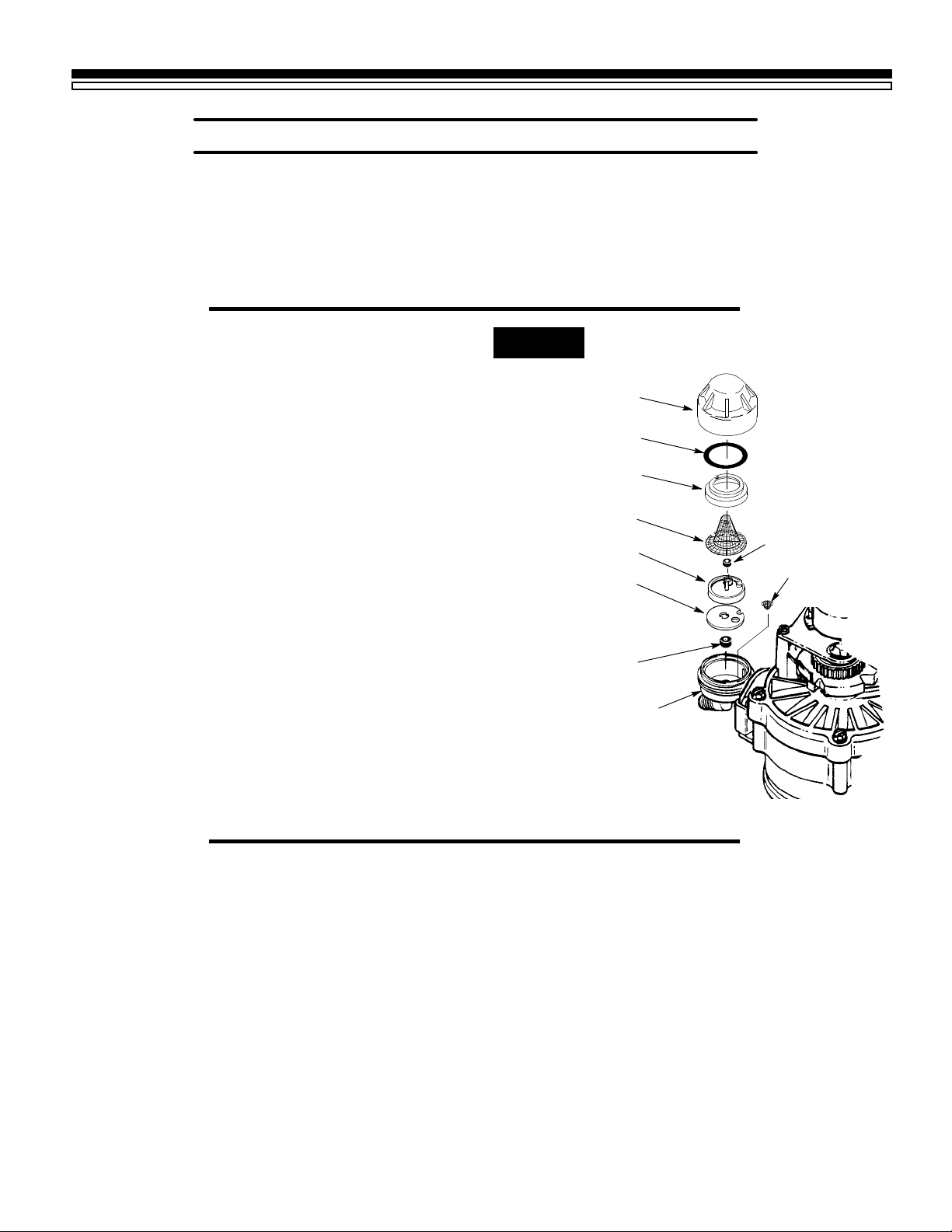
NOZZLE AND VENTURI
Acleannozzleandventuri(FIG.13)isamustfor
thesoftenertoworkright.Thissmallunitmoves
brine from the salt storage tank to the resintank
duringregeneration.If itbecomes pluggedwith
sand, silt, dirt, etc., the softener will not work
and you will get hard water.
To get to the nozzle and venturi, remove the
softener top cover. Be sure the softener is in
service cycle (no water pressure at nozzle and
venturi), then turn off the cap from the nozzle
and venturi housing. DO NOT LOSE THE
LARGE O-RING SEAL. Lift out the screen
supportand screen, then thenozzleandventuri.
Wash and rinse the parts in warm water until
clean.Ifneeded,useasmallbrushtoremoveiron
or dirt. Also check and clean the gasket, small
screen and flow plug.
Carefully replace all parts in the correct order.
Lubricate the o-ring seal with silicone grease or
Vaseline and place in position. Install and
tighten the cap, by hand only. Do not overtigh-
ten and break the cap or housing.
NOTE:
Never use cleaners having ammonia or abrasives. They may scratch and dull the surface.
FIG. 13
Cap
O--ring Seal
Screen Support
Screen
Nozzle & Venturi
Gasket
NOTE: Be sure holes in the
gasketalign with theholesatthe
bottom of the nozzle & venturi
housing.
*Flow Plug
(HVDC)
Nozzle & Venturi
Housing
*INSTALL WITH
NUMBERED SIDE UP
CONCAVE SIDE DOWN.
*Flow Plug
(1--EP)
Screen
IRON FROM THE RESIN BED
Your water softener takes hardness minerals
(calciumandmagnesium)outofthewater.Also,
it can control some “clear water” iron0see
maximum allowed in the specifications on page
21. With clear water iron, water from a faucet is
clear when first put into a glass. After 15 to 30
minutes, the water begins to cloud or turn rust
colored. A water softener WILL NOT remove
any iron which makes the water cloudy or rusty
as it comes from the faucet (called red water
iron).Totake redwater ironout of water,orover
themaximumofclear wateriron,anironfilteror
other equipment is needed. Your local Sears
store has trained people to help you with iron
water problems.
If your water supply has clear water iron, even
thoughless than the maximum allowed, regular
resinbedcleaning is needed.Sears has resinbed
cleaner, Stock No. 42-34426 for this. Clean the
bed at least every 6 months. If iron shows up in
thesoftwater before6 months, clean moreoften.
Printed instructions are on the resin bed cleaner
bottle.
IF YOU HAVE QUESTIONS ABOUT CLEANING AND MAINTAINING YOUR SOFTENER,
CALL TOLL FREE, NUMBER 1-800-426-9345.
15
Page 16
SECTION 3
3C. KEEP THE SOFTENER FROM FREEZING
CARE OF YOUR SOFTENER
If the softener is installed where it could freeze
(summercabin, lake home,etc.), you mustdrain
all water from it to stop possible freezedamage.
To drain the softener —
1. Close the shut-off valve on the house main
water pipe, near the water meter or pressure
tank.
2. Open a faucet in the soft water pipes to vent
pressure in the softener.
3. LookingatFIG.16onpage21,movethestem
in a single bypass valve to bypass. Close the
inlet and outlet valve in a 3-valve bypass
system, and open the bypass valve. If you
want water in the house pipes again, reopen
the shut-off valve on the main water pipe.
4. Unplug the transformer at the wall outlet.
Remove the salt hole cover and the main
cover. Take off both drain hoses.
5. Carefully remove the large holding clips at
the softener inlet and outlet (see Key No. 61,
on page 34). Separate the softener from the
adaptors or bypass valve.
6. Remove the brinewell cover and disconnect
the brine valve tubing at the nozzle and
venturiassembly (see page34). Lift the brine
valveoutof thebrinewell.Tipthebrinevalve
upside down to drain out water.
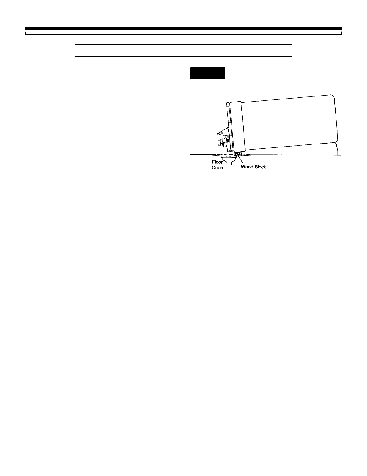
FIG. 14 DRAIN WATER FROM THE
SOFTENER
7. Looking at FIG. 14, lay a piece of 2 inch thick
boardnearthefloor drain. Move thesoftener
close to the drain. SLOWLY and CAREFULLY tip it over until the rim rests on the wood
blockwiththeinletandoutletoverthedrain.
Donotallowthesoftener’s weighttoreston
the inlet and outlet fittings or they will
break.
8. Tipthe bottomofthesoftenerupafewinches
and hold until all water has drained. Leave
the softener laying like this until you are
readyto use it. Plug the inlet and outlet with
rags to keep dirt, bugs, etc. out.
16
Page 17
SECTION 3
WATERHARD
CARE OF YOUR SOFTENER
3D. HELPFUL HINTS CHECKLIST
... TO HELP YOU SAVE MONEY
NOTE:
1. Read “ERROR CODE”, page 9.
2. If your water softener fails to work, make the following easy checks. Often, you will find what’s
wrongyourselfandyouwon’thavetocallandwaitforservice.If,aftermakingthechecks,yoursoftener still does not work right, call your Sears Service Department, or call toll free, number
1-800-426-9345 for telephone assistance.
You can find the model number of your water softener on the rating decal, on the brine tank rim. See
page 32.
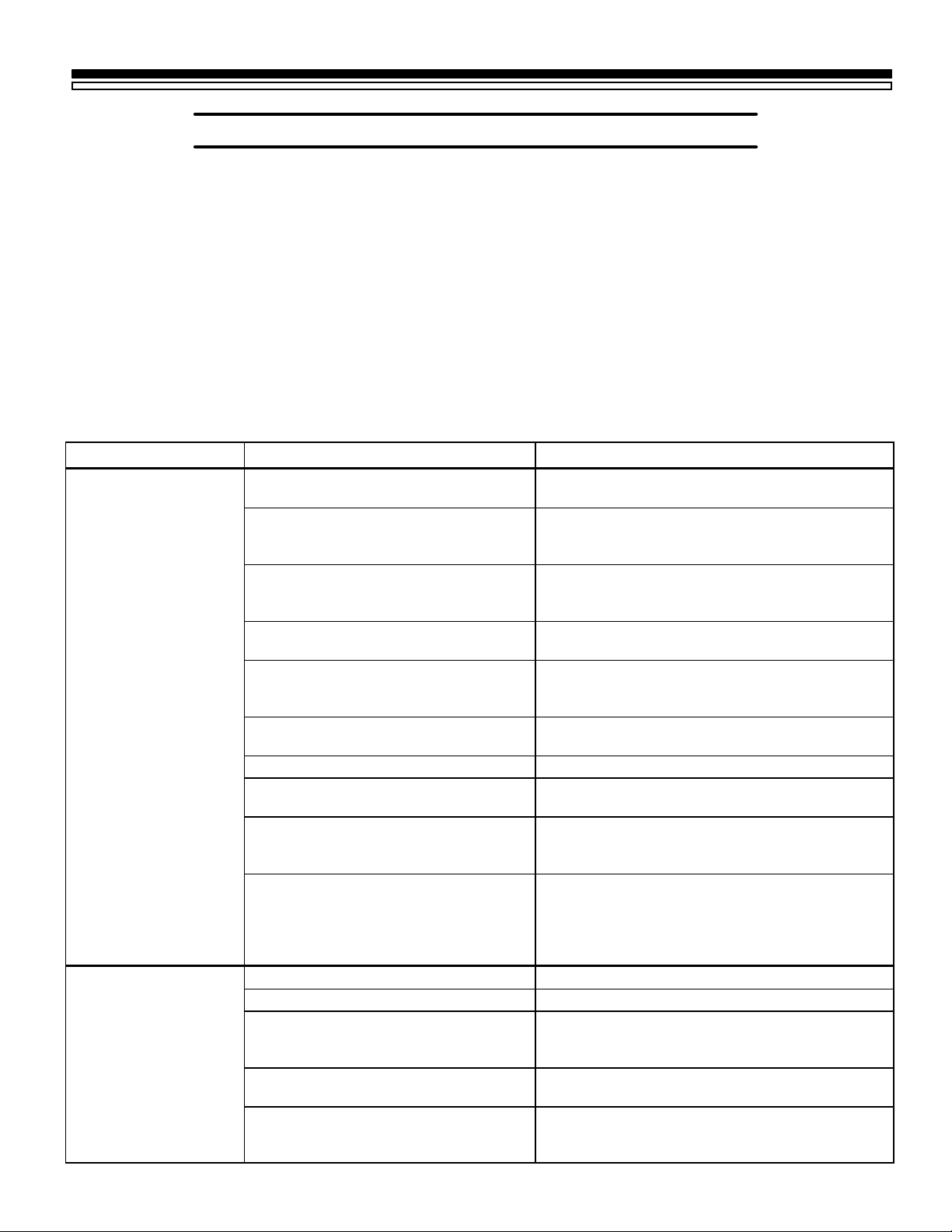
PROBLEM CAUSE CORRECTION
NO SOFT WATER No salt in the storage tank Refill with salt (see page 8). Use the RECHARGE
NOW button to start a regeneration (see page 9).
Transformer unplugged at the wall
outlet, or power cable disconnected
Fuse blown, circuit breaker popped, or
circuit switched off—SEE PAGE 10,
“TIMER POWER-OUTAGE MEMORY”.
Timer in the vacation (VAC) position See VACATION feature to return the softener to
No regenerations set on the timer See pages 18-20 to select and program a
Manual bypass valve(s) in bypass
position
Salt in storage tank bridged Refer to page 14 to break.
Dirty, plugged or damaged nozzle &
venturi
Valve drain hose plugged Hose must not have kinks, sharp bends, or any
Loworhigh system water pressure (Low
pressure may disrupt brine draw during
recharge. High pressures may cause
inner valve parts failure.)
Check for loss of power and correct. Reset the
times, then use the RECHARGE NOW button to
start a regeneration (see page 9).
Replacefuse, resetcircuit breaker, orswitchcircuit
on. Reset times and use the RECHARGE NOW
button to start a regeneration.
service (page 9).
schedule. Use the RECHARGE NOW button to
start an immediate regeneration.
See FIG. 16, page 21. Move stem in single bypass
valve to SERVICE.
Take apart and clean (see page 15) or replace
damaged parts.
water flow blockage (see page 16 in your
installation manual).
If pressure is low, increase well pump output to a
minimumof20 psi.Add apressurereducing valve,
in the supply pipe to the softener, if day time
pressure is over 100 psi (see installation manual).
WATER HARD
SOMETIMES
Regenerations too few Refer to pages 18-20 to find correct setting.
More water being used See pages 18-20 for correct regeneration setting.
Hot water used when softener is
regenerating
Possible increase in water hardness Ask your Sears retail or catalog store for a new
Leaking faucet or toilet valve Asmall leakwill wastehundreds ofgallons ofwater
Avoid using hot water as the water heater refills
with hard water (see “Automatic Bypass” on page
13).
water analysis.
in a few days. Fix all plumbing leaks and always
fully close faucets.
17
Page 18
SECTION 4
4A. HOW TO “FINE-TUNE” YOUR SOFTENER
OTHER THINGS TO KNOW
It is not hard to fine-tune your softener, but it
does take a few minutes of your time to do it
right.You maysave up to500 pounds ormoreof
salt each year with proper tuning. Read the
following carefully.
To have softwater all thetime, the softenermust
regenerate,orrechargeacertainnumberoftimes
in each 7 day period. How many times to
regenerate (set the timer) depends on 3 things.
1. The number of people in your home — tells
you how much water is used.
2. Thegrainspergallon(GPG)hardnessofyour
watersupply—listedonyourwateranalysis
report(see page 2 in your Installation Manual, or page 2 of this manual).
NOTE:
If your water supply contains iron, compensate
for it by adding to the water hardness number.
For example, assume your water is 15 gpg hard and
contains2ppmiron.Add5tothehardnessnumberfor
each1 ppm ofiron.In this example,youwould use 25
for your hardness number.
15 gpg hardness
2 ppm iron x 5 = 10 +10
(times) 25 HARDNESS NUMBER
3. How much salt is used each regeneration —
determinedby the lengthof the fillcycle (see
pages 19 and 20).
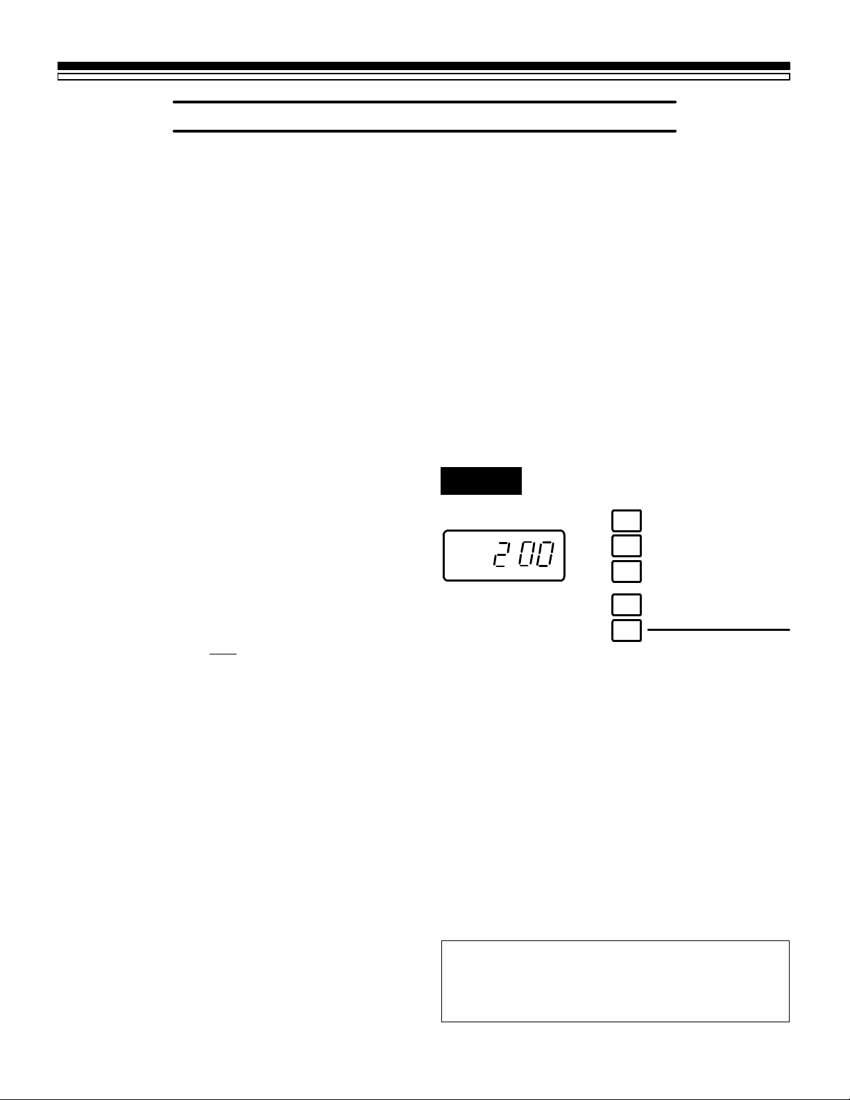
TO SET THE TIMER FOR DAYS OF REGENERATION AND FILL MINUTES, DO THE FOLLOWING.
NOTE:
Remember, the timer is factory set for Monday,
WednesdayandSaturdayregenerationsstarting
at 2:00 AM. Fill time is factory set for 8 minutes.
1. SET DAYS AND TIME OF REGENERATION, OR RECHARGE
a. Press the RECHARGE TIME button © once
to display the factory set regeneration days
andstartingtime(flashing).Tochangetheregeneration start time, do step b following.
Otherwise go to step c.
FIG. 15
PRESENT TIME AND DAY
1
AM
MO WE SA
.
.
NOTE:
Read“Automatic Bypass” page13, whenchoosing a regeneration starting time other than 2:00
AM.
RECHARGE TIME
2
RECHARGE DAY
3
SET / CLEAR
4
ON / OFF VACATION
5
HOLD
RECHARGE NOW
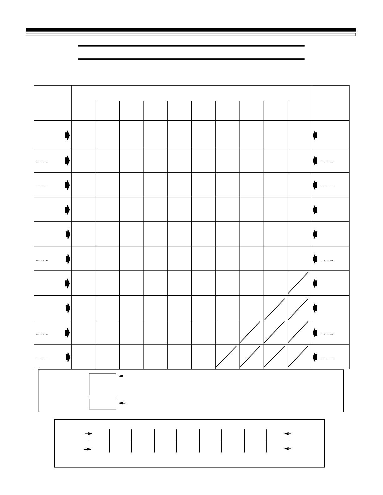
REGENERATION TABLE: The table (page 20)
makesiteasyfoyoutopickthebestregeneration
and fill time setting to use.
Step 1 — Go down the side of the table to the
numberofpersonsinyourfamily,or thenumber
of people in the house using water.
Step 2 — Across the top of the table, find the
column listing the grains per gallon hardness of
your water, or hardness number for iron water.
Step 3 — Readacross and down the table to find
the point where steps 1 and 2 meet. At this
meeting point, suggested days to regenerate,
and fill cycle minutes needed are shown.
b. PresstheSET/CLEARbutton£untilthede-
siredregeneration starting time shows in the
display.
NOTE:
Press SET/CLEAR and quickly release to move
the display ahead 1 hour at a time. Or, hold the
SET/CLEARbuttontomove thedisplayahead2
hours each second.
WRITE IN YOUR RESULTS HERE.
1. M T W TH F S SU Suggested days to
---circle suggested days--- regenerate
2. ______Fill Cycle minutes needed
18
Page 19

SECTION 4
4A. HOW TO “FINE-TUNE” YOUR SOFTENER
OTHER THINGS TO KNOW
c. Press the RECHARGE DAY button ¢ and
SUnday begins to flash.
---- If you want regenerations on Sunday (from
regeneration table), press the SET/CLEAR but-
ton £ to display ON.
----IfyoudonotwantSundayregenerations,press
SET/CLEAR button £ to display OFF.
d. Press the RECHARGE DAY button ¢ again
todisplayaflashingMOndayandON(factory set recharge).As you did in step c, use the
SET/CLEARbutton£tochangethedisplay
from ON to OFF, or from OFF to ON.
2. SET THE FILL CYCLE MINUTES
a. Pressand hold the RECHARGE TIME button
© until FILL shows in the display, then re-
lease button ©. After a few seconds, the fill
cycle minutes (factory setting¼8) will flash.
e. PressRECHARGEDAYbutton ¢todisplay
a flashing TUesday, WEdnesday, etc., each
timeusingtheSET/CLEARbutton£to display either ON or OFF as needed.
After recharge is either set or cancelled for
SAturday, press the PRESENT TIME AND
DAYbutton ¡onceagain to returnthepresent time and day display.
NOTE:
Press SET/CLEAR and quickly release to move
thedisplay ahead 1minute at atime. Or,holdthe
SET/CLEARbuttontomove thedisplayahead2
minutes each second. THE DISPLAY BEGINS
OVER AT 0 AFTER PASSING 59.
b. Press the SET/CLEAR button £ to set the
minutes of fill cycle needed, as shown in the
regeneration table.
NOTE:
You may get hard water between regenerations
ifyousetthetimer forfewerfillminutesthanthe
Regeneration Table shows you to set. A higher
setting than needed will waste salt.
IF YOU NEED HELP TO PROGRAM THE TIMER, CALL TOLL FREE,
NUMBER 1-800- 426-9345.
c. Press PRESENT TIME AND DAY button ¡
to return the present time and day display.
TO SET THE PRESENT TIME OF DAY, AND
DAY OF WEEK, SEE PAGE 6.
19
Page 20
SECTION 4
REGENERATIONTABLE
REGENERATIONTABLE
HOUSEHOLD
HOUSEHOLD
INTHE
INTHE
INTHE
INTHE
INTHE
INTHE
INTHE
INTHE
INTHE
INTHE
INTHE
INTHE
INTHE
INTHE
INTHE
INTHE
INTHE
INTHE
4A. HOW TO “FINE-TUNE” YOUR SOFTENER
SEE INSTRUCTIONS FOR USING THE TABLE, PAGE 18.
OTHER THINGS TO KNOW
WATER HARDNESS -- GRAINS PER GALLON
1
PERSON
IN THE
2
PERSONS
IN THE
HOUSEHOLD
3
PERSONS
IN THE
HOUSEHOLD
4
PERSONS
IN THE
HOUSEHOLD
5
PERSONS
IN THE
HOUSEHOLD
6
PERSONS
IN THE
HOUSEHOLD
7
PERSONS
IN THE
HOUSEHOLD
8
PERSONS
IN THE
HOUSEHOLD
9
PERSONS
IN THE
HOUSEHOLD
10
PERSONS
IN THE
HOUSEHOLD
Up to 5 6 to 10
11 to1516 to2021 to2526 to3031 to3536 to4041 to4546 to
M M M M M M M M M
2 2 2 2 3 3 4 5 2 6
M M M M M
TH
M
TH
M WSM WSM WSM T
2 2 3 5 3 3 2 3 3 2
M M M
TH
M
TH
M WSM WSM WSM T
TH
S
2 3 2 3 3 3 3 3 2 3
M M M
TH
M WSM T
TH F
S
M T
TH
S
M T
TH F
S SU
EVERY
DAY
2 5 3 3 2 3 2 2 3 3
M M
TH
M WSM T
TH F
S
M T
TH F
S SU
M T
TH F
S
M T
TH F
S SU
EVERY
DAY
3 3 3 2 2 3 3 3 4 4
M M
TH
M WSM WSM T
TH
S
M T
TH F
S SU
EVERY
DAY
EVERY
DAY
3 3 3 2 3 3 3 4 5 7
M M WSM WSM T
TH F
S SU
M T
TH F
S SU
EVERY
DAY
EVERY
DAY
EVERY
DAY
4 2 3 2 3 3 4 5
M M WSM T
TH
S
EVERY
DAY
EVERY
DAY
EVERY
DAY
EVERY
DAY
EVERY
DAY
5 3 3 2 3 4 5 8
M
TH
M WSM T
TH F
S SU
M T
TH F
S SU
EVERY
DAY
EVERY
DAY
EVERY
DAY
2 3 2 3 4 5 8
M
TH
M T
TH F
S
M T
TH F
S
EVERY
DAY
EVERY
DAY
EVERY
DAY
3 2 3 3 4 7
TH
M T
TH F
S SU
M T
TH F
S SU
EVERY
DAY
EVERY
DAY
EVERY
DAY
8
50
M
TH
TH F
S
M T
TH F
S
EVERY
DAY
EVERY
DAY
EVERY
DAY
1
PERSON
IN THE
2
PERSONS
IN THE
HOUSEHOLD
3
PERSONS
IN THE
HOUSEHOLD
4
PERSONS
IN THE
HOUSEHOLD
5
PERSONS
IN THE
HOUSEHOLD
6
PERSONS
IN THE
HOUSEHOLD
7
PERSONS
IN THE
HOUSEHOLD
8
PERSONS
IN THE
HOUSEHOLD
9
PERSONS
IN THE
HOUSEHOLD
10
PERSONS
IN THE
HOUSEHOLD
LEGEND:
M T W
TH F
S SU
4
DAYS TO REGENERATE: M = Monday, T = Tuesday, W = Wednesday
TH = Thursday, F = Friday, S = Saturday, SU = Sunday
(factory set for Monday, Wednesday and Saturday)
MINUTE-LENGTH OF FILL CYCLE NEEDED
(factory set for 8 minutes)
MINUTES OF FILL @ 0.3 GPM
minutes
pounds
2 3 4 5 5 7 8 9 10 minutes
1.8
2.7 3.6 4.5 5.4 6.3 7.2 8.1 9
pounds
POUNDS OF SALT USED EACH REGENERA TION
20
Page 21
SECTION 4
4B. DIMENSIONS/SPECIFICATIONS
OTHER THINGS TO KNOW
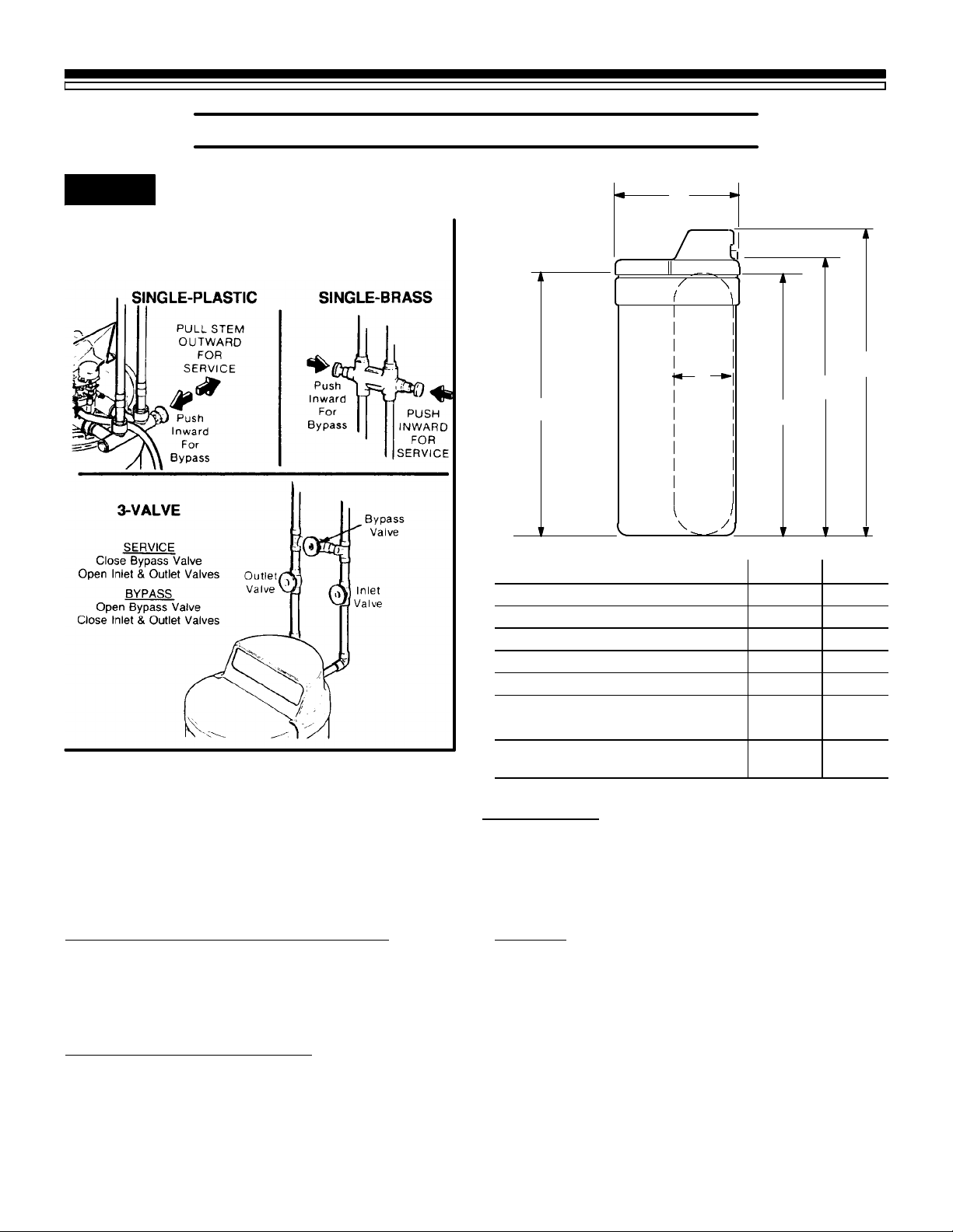
FIG. 16 BYPASS VALVES
Bypassvalve(s)shouldalwaysremaininsoft
water service position. Position in “bypass”
only if needed for softener repairs.
F
B
A
INCHES CM
A Salt Tank Height 40-1/4 102.2
B Resin Tank Diameter(nominal) 8 20.3
C Resin Tank Height (nominal) 40 101.6
D Inlet-Outlet Height 41-1/2 105.4
E Overall height 46 116.8
F1Length 19-1/2 49.5
F2Width 16-1/2 41.9
— Distance between inlet-outlet
center lines
3-3/8 8.6
D
C
E
MODEL NO. 625.348321
NOTE:
Please see the rating decal for water softener operating capacity,salt usageand service flow rate/pressur eloss
performancespecifications.Performancespecificationsarevalidatedbythe WaterQuality Association(WQA).
The rating decal is located on the rim, under the salt hole cover (see page 32).
WATER SUPPLY TO WATER SOF TENER
MINIMUM WATER SYSTEM FLOW (gpm) 3
MINIMUM-MAXIMUM WATER PRESSURE (psi) 20-120
MAXIMUM WATER TEMPERATURE (5F) 120
MAXIMUM WATER HARDNESS (gpg) 50
MAXMUM “CLEAR WATER” IRON (ppm) 2
SALT FOR WATER SOF TENER
TYPE OF SALT NEEDED Nugget/Pellet
ALTERNATE TYPE OF SALT Pure, evaporated, compacted
water softener salt
STORAGE CAPACITY (pounds) 200
OTHERS
TYPE OF ION EXCHANGE MATERIAL (resin) High Capacity
AMOUNT OF RESIN (cu.ft.) .52
REGENERATION (RECHARGE) CYCLE TIME (min.)
FILL (factory setting-time is adjustable) 8
BRINING/BRINE RINSE 80
BACKWASH 12
FAST RINSE 4
TOTAL REGENERATION TIME (factory setting) 118
gpm = gallons per minute psi = pounds per square inch
gpg = grains per gallon ppm = parts per million
21
Page 22
SECTION 5
SERVICE TECH. INFORMATION
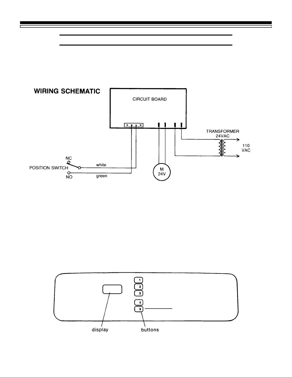
5A. ELECTRICAL CONNECTIONS
IMPORTANT:
Keepthismanualwithyourwatersoftener.Ifrepairsareneeded,theservice technician must havethe
information on the following pages. For telephone assistance, call toll free, 1-800-426-9345.
FACEPLATE TIMER
PRESENT TIME
RECHARGE TIME
RECHARGE DAY
SET / CLEAR
ON / OFF
VACATION
HOLD RECHARGE NOW
22
Solid State Water Softener
Page 23
SECTION 5
(flowtodrain)
5B. REGENERATION CYCLE TIMES
SEE REGENERATION TABLE ON PAGE 20, AND SPECIFICATIONS, PAGE 21.
FILL (flow to salt storage tank) 0.3 (1.1 liters)
BRINING .16 (.6 liters)
BRINE RINSE
BACKWASH
FAST RINSE 1.8 (6.8 liters)
SERVICE TECH. INFORMATION
CYCLE FLOW RATES (GALLONS PER MINUTE)
.11 (.4 liters)
1.8 (6.8 liters)
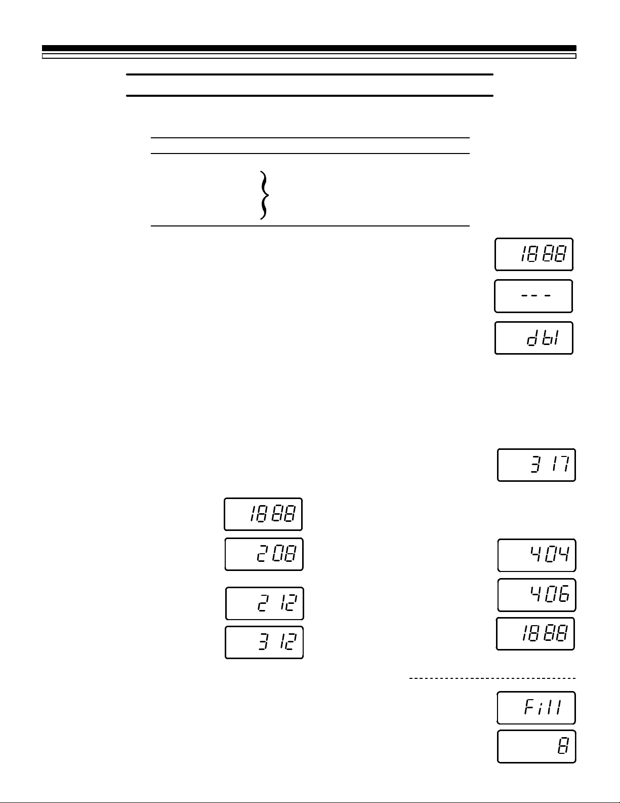
TOSETDOUBLE BACKWASH(Softenerhasabackwashandfastrinsecyclebeforebrining,and
after brining, which is beneficial on some kinds of iron bearing water):
USE BUTTONS £ (SET/CLEAR), and ¡ (PRESENT TIME AND DAY)
AM
PM
RCHG
MO WE TH FR SA
SU
.
.
TU
1. Press and hold £ entire display comes on.. . . . . . . . . . . . . . .
" Press ¡ to display 3 dashes
" Press £ to display dbl
" Press ¡ to display 18:88
2. Press £ to return present time.
REPEAT ABOVE STEPS TO CANCEL DOUBLE BACKWASH.
CYCLESEQUENCEWITH DOUBLE BACKWASH:1. Fill 2. Backwash 3. FastRinse 4. Brining/BrineRinse 5. Back-
wash 6. Fast Rinse — Return to Service
OTHER RECHARGE CYCLE TIME ADJUSTMENTS
Cycle times in specifications are factory settings. Do the following to check for correct cycle times.
NOTE: Removing from electrical power (varies from 6 to
15 hours) resets timer to factory programming.
DISPLAY MUST SHOW TIME AND DAY
1. Press and hold £ ¼entiredisplay
comes on.
PM
RCHG
MO WE TH FR SA
SU
.
.
TU
AM
2. Press © ¼2:08 shows; meaning
#2 cycle (brining & br. rinse) and
80 minutes (8 x 10).
.
.
a. If 2:08 does show, go to step 3.
b. If other than 2:08 (2:00 to 2:15),
press £ until 2:08 shows.
3. Press © ¼3:12shows, meaning
#3 cycle (backwash) and 12 minutes.
.
.
.
.
a. If 3:12 does show, go to step 4.
.
.
b. If other than 3:12 (3:00 to 3:30),
press £ until 3:12 shows.
NOTE: Instead of programming a double backwash, a
longersinglebackwash is beneficial on sometypesofiron
water.
.
4. Press © ¼4:04shows; meaning
.
#4 cycle (fast rinse) and 4 minutes.
a. If 4:04 does show, go to step 5.
.
.
b. If other than 4:04 (4:00 to 4:30),
press £ until 4:04 shows.
5. Press © ¼18:88 shows.
AM
PM
RCHG
MO WE TH FR SA
SU
.
.
TU
6. Press £ ¼toreturn to present time and day .
TO SET MINUTE — LENGTH OF FILL CYCLE (factory setting, 8 minutes)
USE BUTTONS © (RECHARGE TIME), £ (SET/CLEAR),and ¡ (PRESENT TIME AND DAY)
1. Press and hold © until FILL shows, then 16 (factory setting).
" Press £ to set the desired fill minutes
(from regeneration table).
2. Press ¡ to return present time and day.
23
Page 24
SECTION 5
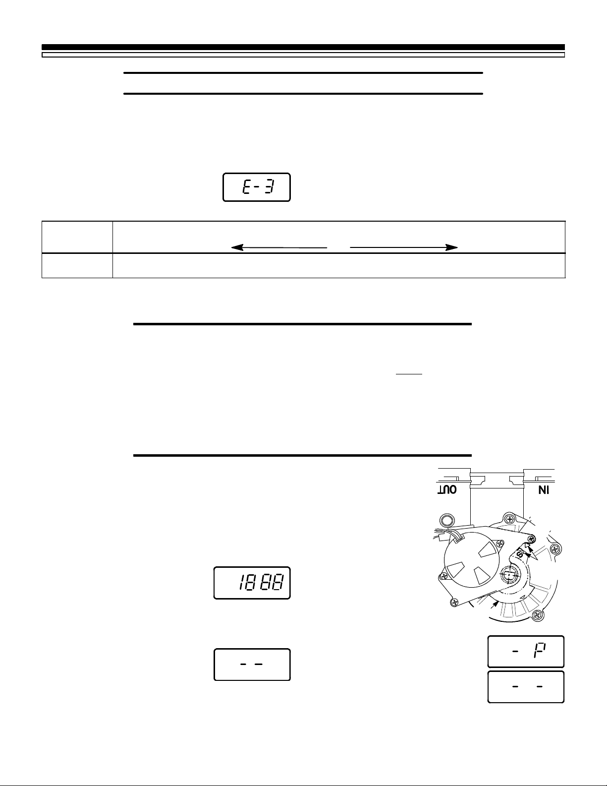
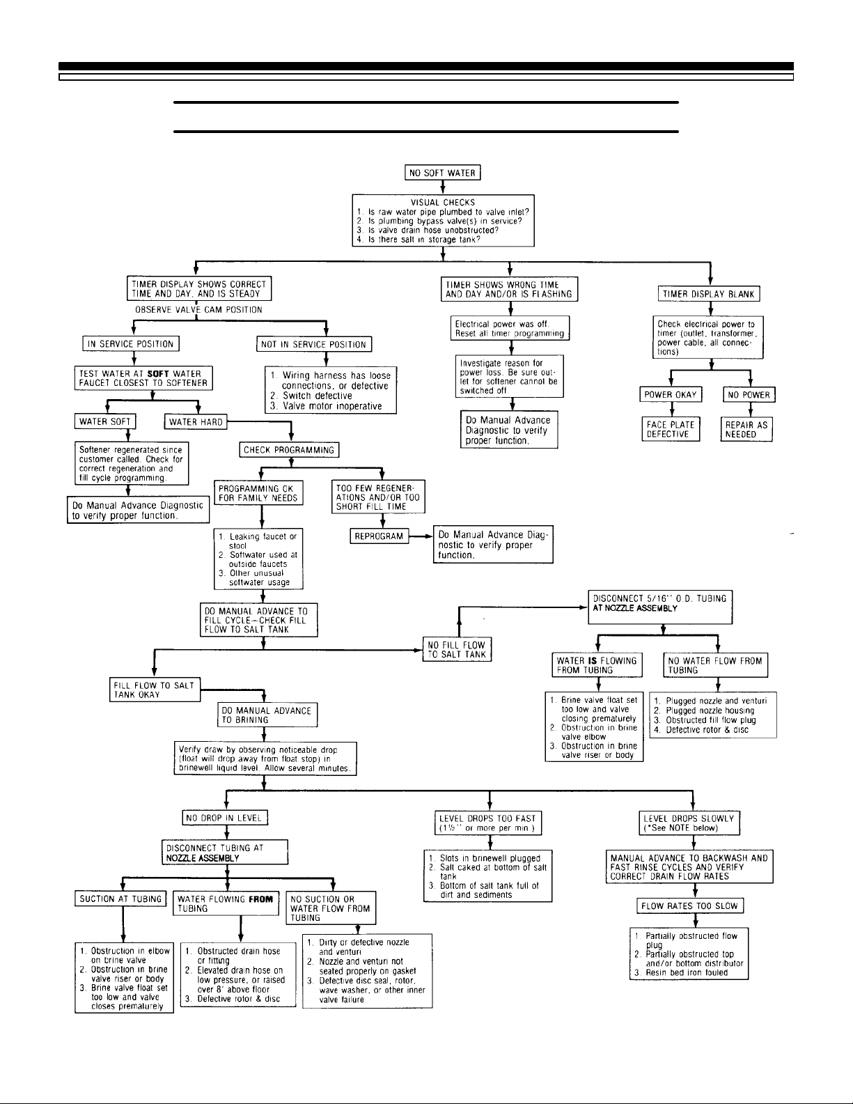
E—1,E—2,wiringharnessorconnectiontoswitch/positionswitch/motorinoperative/valvedefectcausingE—3,E—4hightorque
5C. TROUBLESHOOTING
SERVICE TECH. INFORMATION
AUTOMA TIC ELECTRONIC DIAGNOSTICS
The face plate has a self-diagnostic function for the
electricalsystem(exceptinputpower). Thefaceplate
monitors the electronic components and circuits for
correct operation. If a malfunction
occurs,anerrorcodeappearsinthe
face plate display.
The chart below shows the error codes that could
appear ,and the possible defects for each code.
While an error code appears in the display, all face
plate buttons are inoperable except the SET button.
The SET button remains operational so the service
person can make the MANUAL ADVANCE DIAGNOSTICS to further isolate the defect.
POSSIBLE DEFECT
CODE
MOST LIKELY LESS LIKELY
PROCEDURE FOR REMOVING ERROR CODE FROM FACEPLATE: 1. Unplug transformer 2. Correct defect 3. Plug-in transformer 4. Wait for 6 minutes. The error code will return if the defect was not corrected.
FACE PLATEREPLACEMENT: Be sure the valve is in service position (observe valve cycle indicator.. . see
below) when replacingthe face plate.
If, after installing and programmingthereplacementfaceplace,the valve is not in service position, do the following to assure correct cycle orientation, or timing, between the face plate and valve.
Use the MANUAL ADVANCE procedures, below .Withthe RECHARGE NOW button, advance through the
recharge cycles until the valve stops in service position, and RECHARGE no longer flashes in the timer.
NOTE: The valve motor may automatically drive through several valve positions while sear chingforservice.
MANUAL ADVANCE DIAGNOSTIC
Use the following procedures to advance softener
valve through regeneration cycles to check operation.
While the valve is rotating from 1 cycle to
another , the display
will show(- P), meaningthepositionswitch
Remove top cover to observe valve rotation.
DISPLAY MUST SHOW TIME AND DAY
1. Press and hold £ for 3 seconds
until 18:88 displays.
PM
RCHG
MO WE TH FR SA
SU
.
.
TU
AM
2. Press ¢ to display position (P) switch open or
closed indicator.
If the valve is in service, fill, brining, backwash or fast rinse (see
markingsoncamundermotor),the
display will show¼(- -), meaning
the position switch is open.
is closed.
3. T o advance valve,
press ¤ each time
MOTOR
you want to move
into next cycle.
(Pressing ¤ while
valve is rotating
CAM
has no affect.)
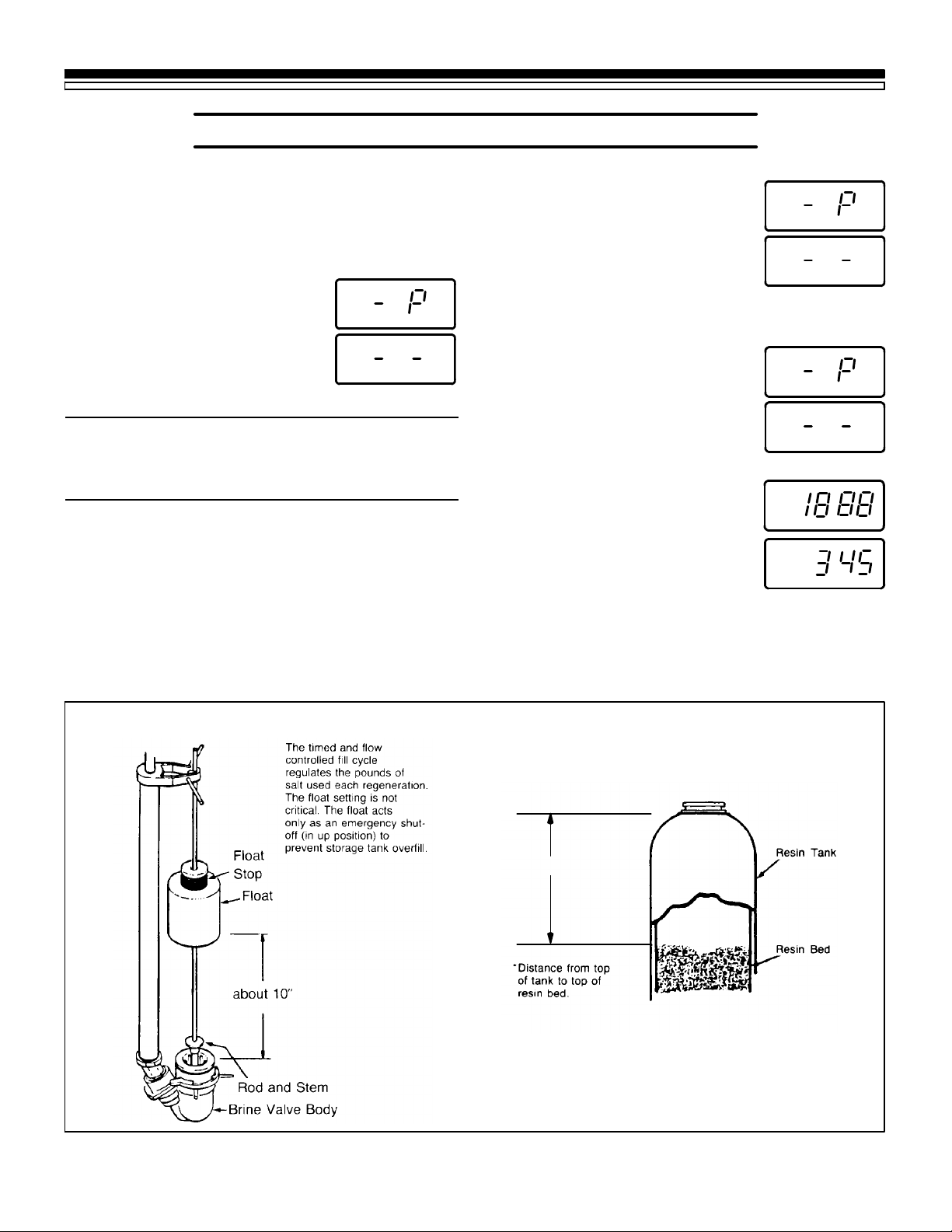
—Pressandhold¤for3 seconds to
move softener into fill cycle. Remove brinewell cover and, usinga
flashlight, observe fill water entering tank.
position
markers
continued
24
Page 25
SECTION 5
5C. TROUBLESHOOTING
SERVICE TECH. INFORMATION
a. If it does not move into fill, valve motor is inop -
erative. Check all wiring and connections.
b. If water does not enter tank, see “Quick-Check
Troubleshooting,” page 26.
— After fill, press ¤ to move
softener into brining. A slow flow
of water to drain begins. Verify
brine draw from brine tank. See
flow rates on page 23.
NOTE: WHILE IN MANUAL ADVANCE, THE
TIME DISPLAY WILL AUTOMATICALLY RETURN TO THE PRESENT TIME IF A BUTTON IS
NOT PRESSED WITHIN 4 MINUTES.
c. If softener does not draw brine¼see “Quick -
Check Troubleshooting”.
NOTE: Be sure a salt bridge is not preventing water
with salt contact.
—Again press ¤to move softener
intobackwash.Lookfor afastflow
of water from drain hose.See flow
rates, page 23.
d. An obstructed flow indicates a
plugged top distributor, backwash flow plug, or drain hose.
—Press ¤ to move softener into
fast rinse. Again look for fast drain
flow. Allow softener to rinse for a
few minutes to flush out anybrine
remaining in resin tank from brining cycle test.
—To return softener to service,
press ¤.
4. Press ¢ to display 18:88.
5. Press £ toreturnpresent time
and day.
AM
PM
RCHG
MO WE TH FR SA
SU
PM
MO
.
.
TU
.
.
BRINE VALVE FLOAT SETTING FREEBOARD MEASUREMENT
Freeboard*
25
Page 26
SECTION 5
5C. TROUBLESHOOTING
SERVICE TECH. INFORMATION
*NOTE: Proper draw indicated.Be
sure to check for a salt bridge. As a
positive check for brine draw into the
resintank,keep softener in briningfor
20 minutes or more. Then, make a
taste test for salt at the drain water.
26
Page 27
SECTION 5
5D. ROTARY VALVE SERVICE
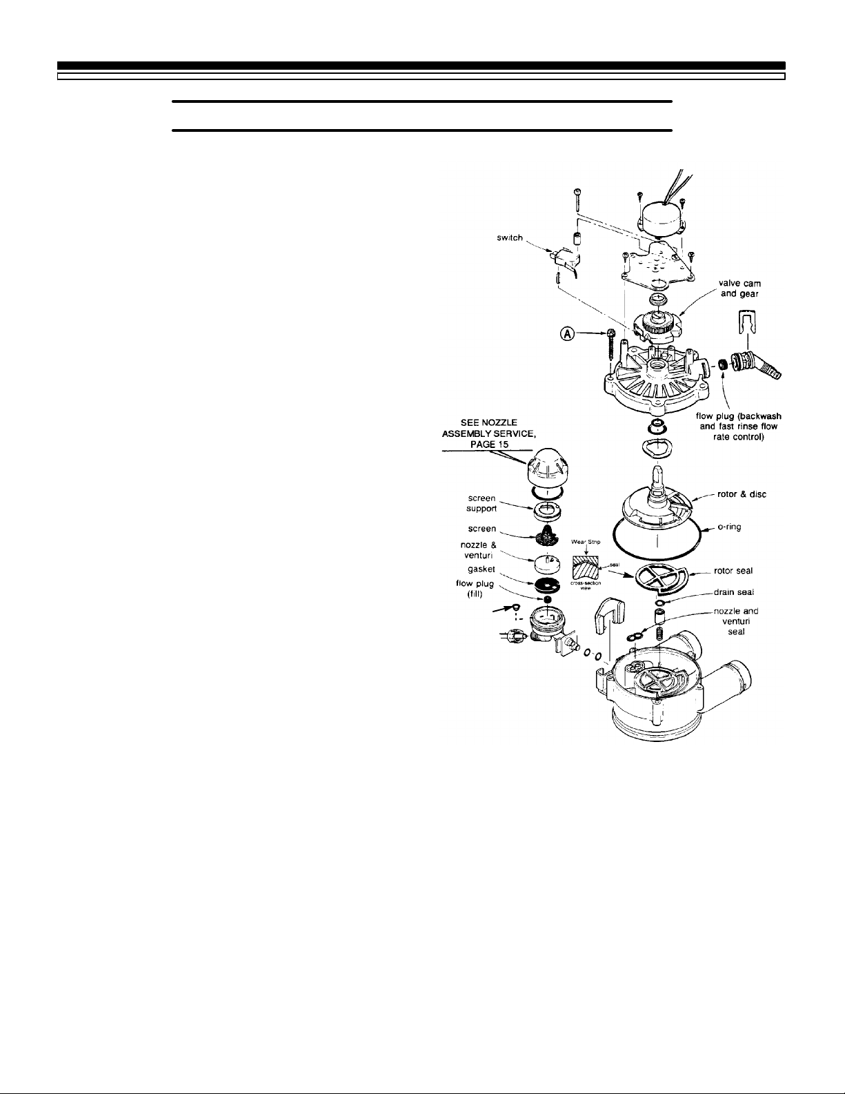
Before working on the valve, turn off the water
supply and disconnect from electrical power. TO
RELIEVE PRESSURE:
-- 3VALVE BYPASS:Closetheinletvalveandopena
soft water faucet. Then close the outlet valve and
open the bypass valve.
-- SEARS SPECIAL BYPASS:Slide the bypass valve
stemtobypassposition.Loosenthe3hex headscrews
(see A in drawing) toward the back side of the valve
toallowpressurewatertobleedout(catchwaterwith
a rag).
DISASSEMBLY
To removea part or groupof parts, referto the valve
drawing. A common screwdriver or nut driver,
Phillips screwdriver and pliers are the only tools
needed to completely disassembe.
SERVICE TECH. INFORMATION
SERVICING THE VALVE
Inspect all o- rings, seals and gaskets for wear or
defects.
Inspect the bottom surface of the rotor and disc for
scratches, chips or wear .
NOTE: If replacement is needed, be sur e to use the
current replacement part.
ASSEMBLY
Be sur e all parts are in place and in the proper
position. Lubricate ALL o-rings and seals with FDA
approved silicone grease. To install the rotor seal,
first place the seal into the valve groove, rounded
side down (see cross- section). Apply a light coating
of silicone grease to the seal’s crossing ribs. Then,
carefullycenter thewearstripontheseal,andpushit
downward onto the seal.
Install the nozzle and venturi seal and drain seal.
Assemble 2 o-rings and the wave washer onto the
rotor and disc. Then center the rotor and disc, in the
valve body, on the rotor seal.
Lowerthe cover onto the valve bodyand rotorshaft.
Then install the cover holding screws. Before tight-
ening the screws, install the valve cam and gear.
Then, turn the rotor (clockwise only) to service
position. T ighten the screws using a criss-cross
pattern. If a torque wrench is available, torque to
30-40 inch pounds.
screen
Lubricate the gear on the motor, and the valve cam
gearwithMolykotegrease,orotherhighqualitygear
lubricant.
Be sure to orient switch as shown,withlevertoward
the cam.
27
Page 28
SECTION 5
SERVICECYCL
E
FILLCYCLE
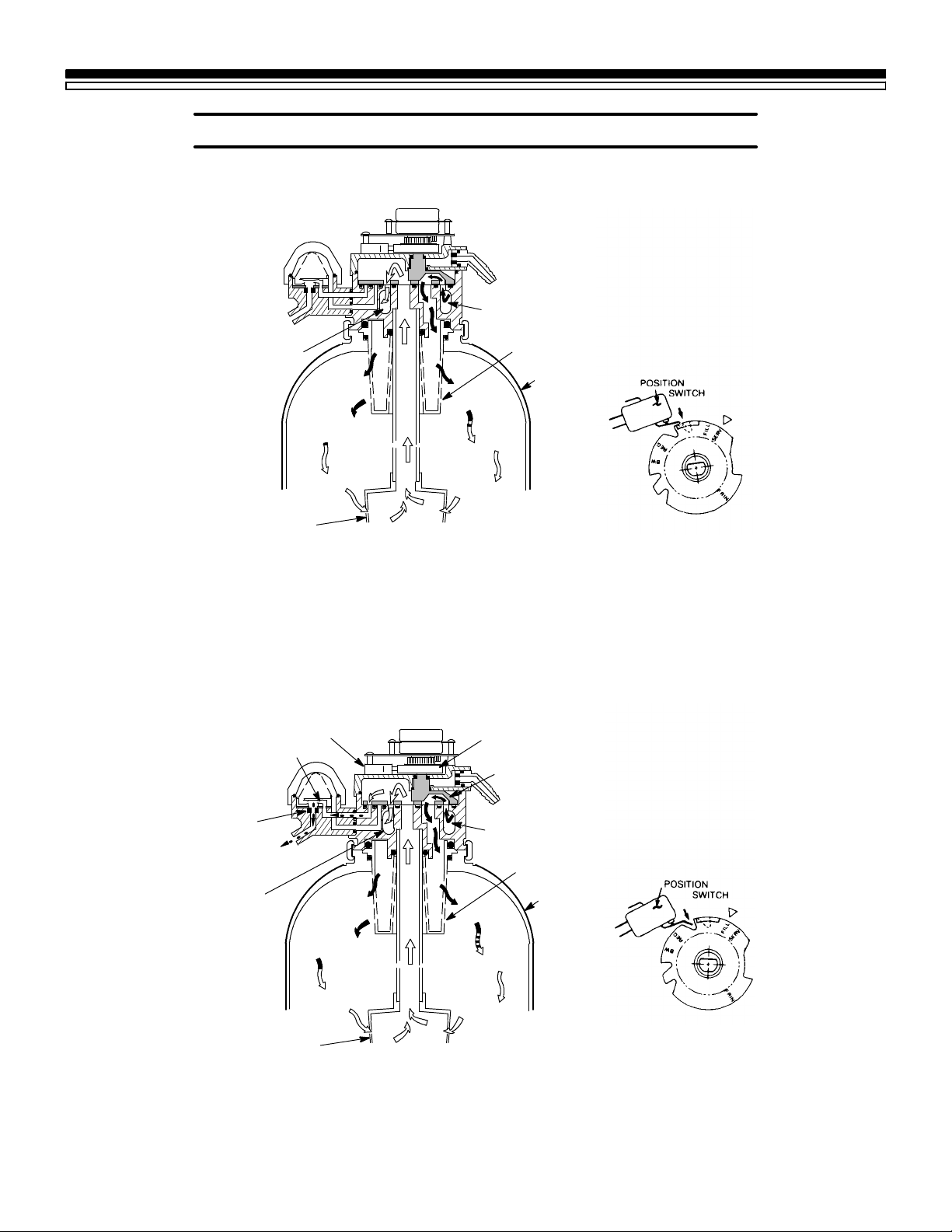
5E. WATER FLOW THROUGH THE SOFTENER VALVE
SERVICE TECH. INFORMATION
from Valve Inlet
(hard water)
To Valve Outlet
(soft water)
resin
bed
bottom distributor
Hardwaterenters thevalve inletport.Internal valveportingroutes thewaterdown and
outthetop distributor, intotheresintank.Hardwater issoftenedasit passesthroughthe
resinbed,thenenters thebottomdistributor.Softwaterflows backinto thevalveand out
the valve outlet, to the house soft water pipes.
position switch
venturi
resin
bed
top distributor
resin tank
valve cam
rotor & disc
fill flow
plug
fill water
(soft)
To Valve Outlet
(soft water)
resin
bed
bottom distributor
To begin a regeneration, the solid state timer energizes the circuit to the valve motor. The
valvemotorrotatestherotoranddiscandthe valvecamuntilthe positionswitchleverdrops
to open the motor circuit and position the valve in FILL. As the rotor and disc rotates, the
portopensfor SOFTwaterfillthroughtheventuri.Fillflowcontinuesto thebrinevalve,and
into the salt storage tank. Soft water is still available to the house lines.
from Valve Inlet
(hard water)
top distributor
resin tank
resin
bed
28
Page 29
SECTION 5
5E. WATER FLOW THROUGH THE SOFTENER VALVE
bypass hard water
to valve outlet
venturi
SERVICE TECH. INFORMATION
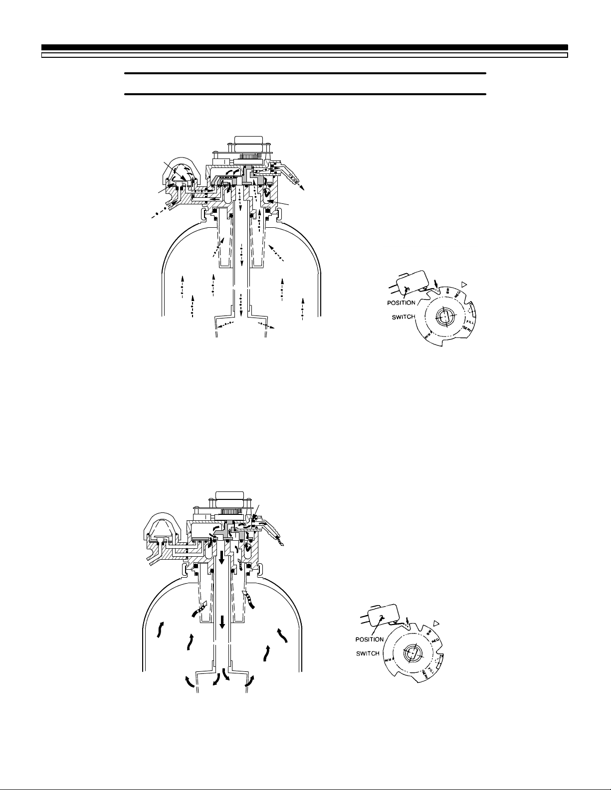
BRINING AND BRINE RINSE CYCLES
nozzle
brine from
salt storage tank
After fill,timer/switch action allows themotor to turnthe rotorand discinto BRINING position.
Waterflow isdirected tothe nozzle. Suction,created bythe nozzleand venturi, drawsbrine from
thesalt storagetank andinjects itinto theresin bedvia thebottomdistributor.Flowcontinues out
the top distributor and to the drain. Hard water is available at the valve outlet.
Whenthebrinevalveclosestoendbrinedraw,waterflowcontinuesinthesamedirectionstoslowly RINSE brine from the resinbed and to the drain.
drain
from Valve Inlet
(hard water)
BACKWASH CYCLE
bypass hard water
to valve outlet
flow plug
drain
29
Timer/switchaction again allows the motor
to turn the rotor & disc to place the valve in
BACKWASH, stopping water flow to the
nozzle.Waterisrouteddownandoutthebottom distributor, up through the bed, andout
the topdistributor to the drain.The fastflow
(controlledbyaflow pluginthedrainfitting)
flushes dirt, sediments, iron deposits, remaining brine and hardness to the drain.
Page 30
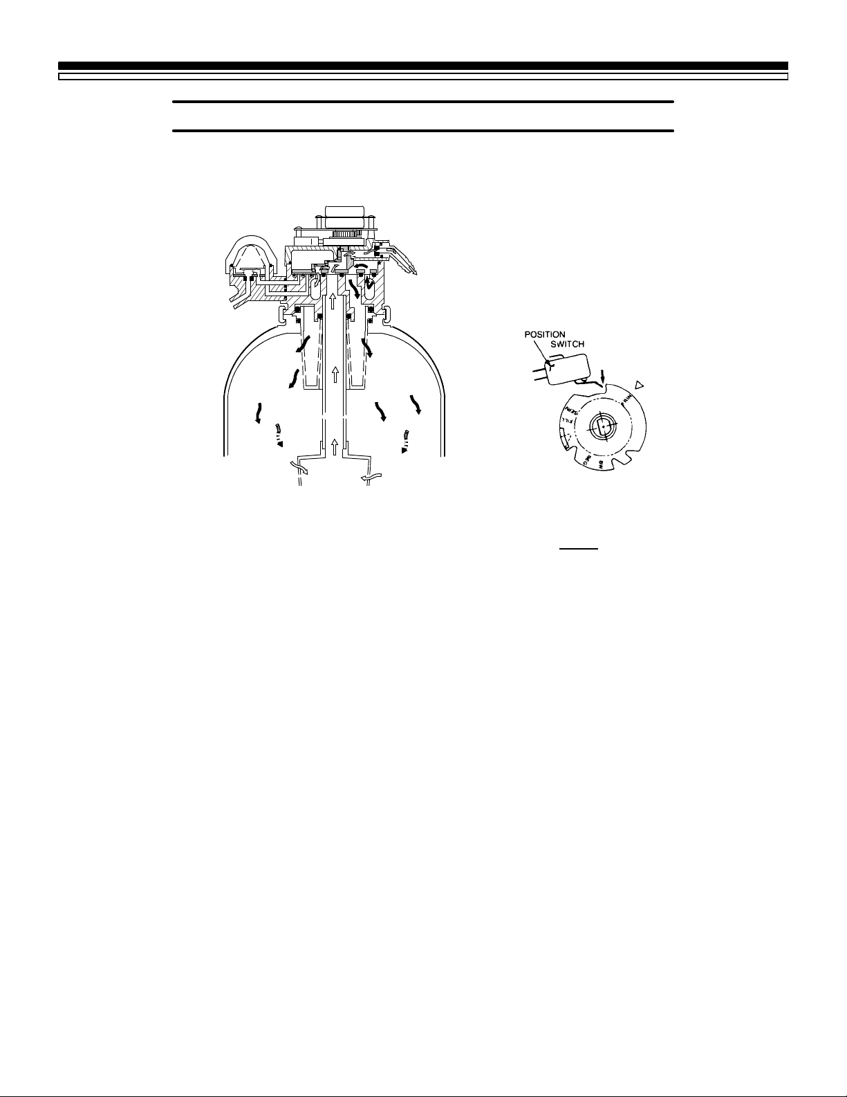
SECTION 5
5E. WATER FLOW THROUGH THE SOFTENER VALVE
soft water
to valve outlet
SERVICE TECH. INFORMATION
FAST RINSE CYCLE
drain
During FAST RINSE, the rotor & disc is positioned so water flow enters the resin tank
through the top distributor, and exits through the bottom distributor,to the drain.
The solidstate timer again energizesthe motor toreturn the valveto service, andas the
valverotates, theposition switchlever dropstoopen thecircuit.The valveremainspositioned in service until the timer initiates the next regeneration.
30
Page 31

SECTION 5
SERVICE TECH. INFORMATION
NOTES
31
Page 32
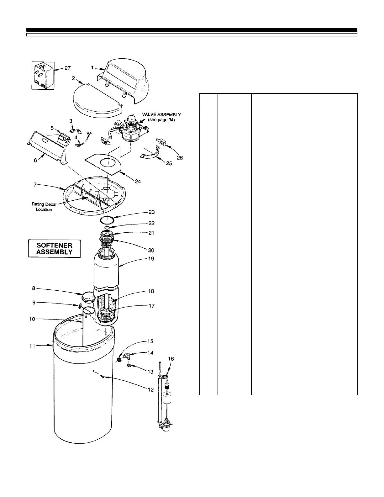
SECTION 6
REPAIR PARTS
SEARS WATER SOFTENER
MODEL NO. 625.348321
KEY
NO.
1 7137604 Cover (main)
2 7137612 Salt Hole Cover
3 7118333 Wire Harness (switch)
4 7132840 Power Cord (transformer)
5 7144978 Timer Repl. (PWA)
6 7137581
7 7137599 Rim
8 7137727 Brinewell Cover
9 7082150 Wing Nut, 1/4²
10 7100819 Brinewell
11 7144619 Salt Storage Tank
12 7148875 Screw, Plastic, 1/4² x 5/8²
13 0900431 Tube Clamp F
14 1103200 Tube Adaptor F
15 9003500 Grommet F
16 7116488 Brine Valve Assy. (also see pg. 33)
17 7105047 Replacement Distributor
18 0501741 Resin
19 7092155 Resin Tank (incl. Key No. 18)
20 7170270 O-Ring, 2-3/4² x 3²
21 7077870 Top Distributor
22 7170254 O-Ring, 13/16² x 1-1/16²
23 7170296 O-Ring, 2-7/8² x 3-1/4²
24 7141001 Vapor Barrier
25 7176292 Clamp Section (2 req.)
26 7088033 Clamp Retainer (2 req.)
27 7095373 Transformer, 24V-10VA F
P ART
NUMBER DESCRIPTION
Face Plate (order decal below)
7155872
Face Plate Decal
32
7159931 Installation Manual
z
7199012 Owners Manual
z
z not illustrated
F Included in parts bag¼see page 35.
Page 33
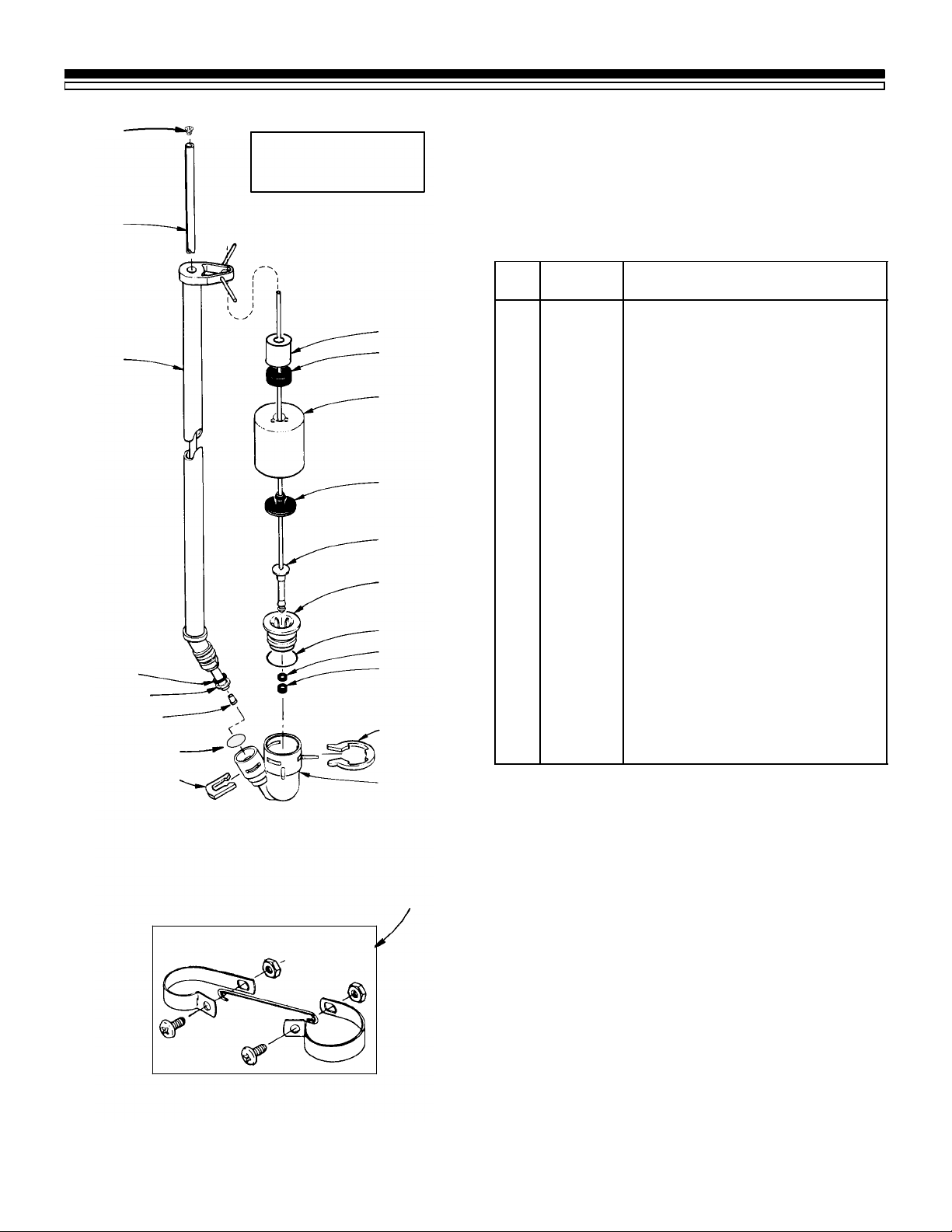
SECTION 6
48
REPAIR PARTS
BRINE VALVE
ASSEMBLY
SEARS WATER SOFTENER
47
46
45
44
43
42
41
11 12
30
31
32
33
34
35
36
37
38
39
40
MODEL NO. 625.348321
KEY
NO.
30 7168647 Ceramic Weight
31 0513860 Float Stop
32 7097202 Float (Includes Key No. 33)
33 0516947 Float Seal
34 7093216 Float Rod & Stem
35 7092278 Guide Cap
36 7170288 O-Ring 15/16 x 1-3/16
37 0516211 Seal
38 0516924 Retainer, Bottom Seal
39 7116713 Clip
40 7092252 Brine Valve Body
41 7080653 Clip
42 7131365 Screen
43 7094979 Insert
44 7092294 Retaining Ring
45 7176161 O-Ring, 5/16 x 9/16
46 7095470 Brine Tube
47 7113016 Tubing Assembly (Includes Key
48 7171349 Cone Screen
49 7112997 Ground Clamp Kit F
F Included in small parts bag¼see page 35.
P ART
NUMBER DESCRIPTION
Nos. 43, 44 & 45)
INLET --- OUTLET
GROUNDING CLAMPS
49
33
Page 34
SECTION 6
REPAIR PARTS
SEARS WATER SOFTENER
MODEL NO. 625.348321
VALVE ASSEMBLY
82
81
80
79
78
77
83
84
13
14
34
Page 35
SECTION 6
REPAIR PARTS
SEARS WATER SOFTENER
MODEL NOS. 625.348321
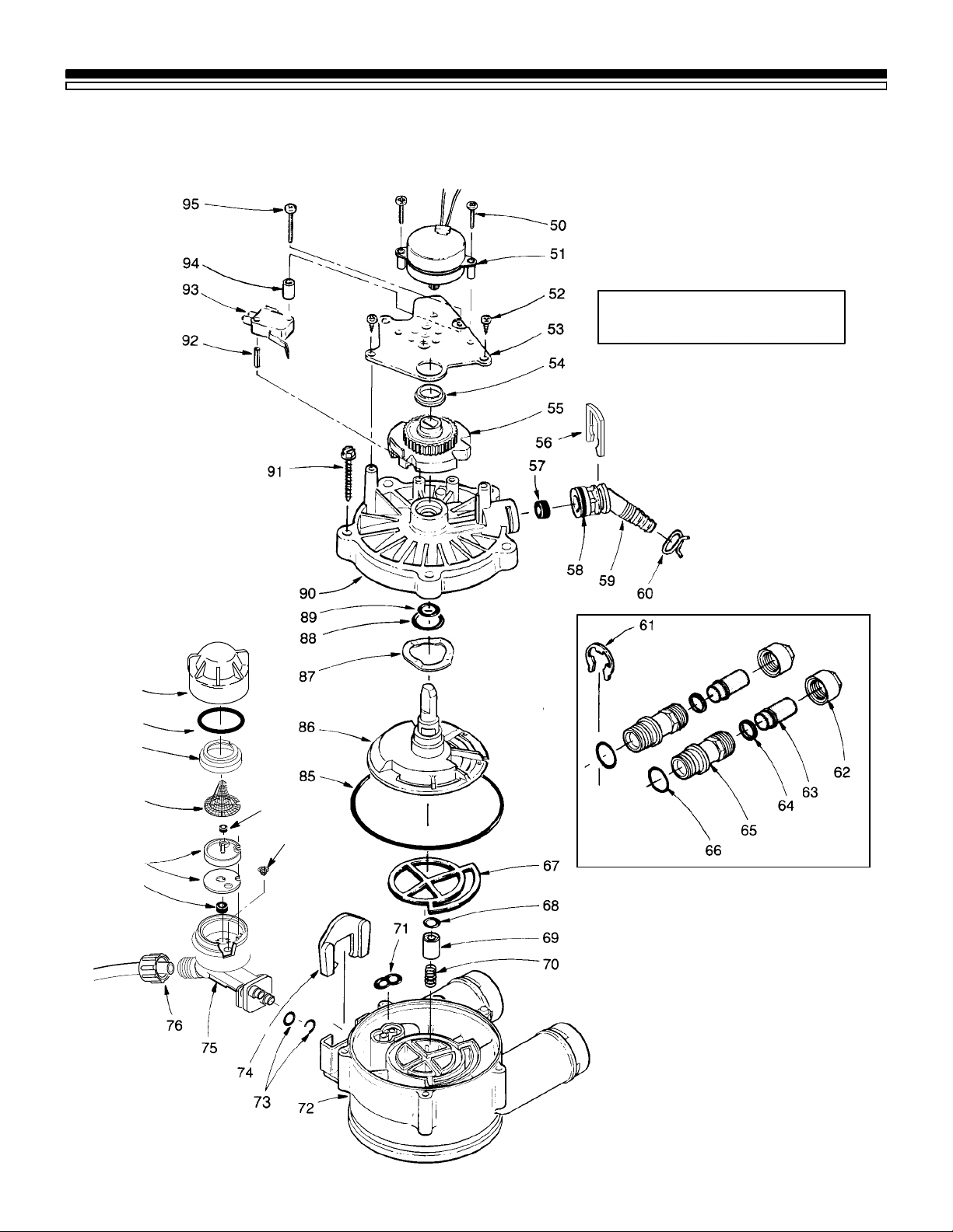
PARTS LIST
KEY
NO.
50 7131755 Screw, #6-20 x 7/8 (2 req.)
51 7133008 Motor (incl. 2 ea. of Key No. 50)
52 0900857 Screw, #6-20 x 3/8 (2 req.)
53 7117808 Motor Plate
54 0503288 Bearing
55 7113927 Cam and Gear
56 7142942 Clip (Drain)
57 0501228 Flow Plug
58 7170327 O-Ring, 5/8 x 13/16
59 7024160 Drain Hose Adaptor
60 0900431 Tube Clamp F
61 7116713 Clip (2 req.) F
62 0507369 Installation Nut (2 req.) ¡
63 0507615 Installation Tube (2 req.) ¡
64 7170335 Washer (2 req.) ¡
z 42-3441 Installation Kit (includes Key Nos.
65 2207800 Installation Adaptor (2 req.) F
66 7170288 O-Ring, 15/16 x 1-3/16 (2 req.) F
67 7134224 Rotor Seal
68 7170204 O-Ring, 3/8 x 9/16
69 7092642 Plug (Drain Seal)
70 7129889 Spring
71 7081764 Seal (Nozzle & Venturi)
72 7082053 Valve Body
73 7170319 O-Ring, 1/4 x 3/8 (2 req.)
74 7081201 Retainer (Nozzle & Venturi)
75 7081104 Nozzle & Venturi Housing
76 1202600 Nut — Ferrule
77 1148800 Flow Plug, .3 gpm
¡ PARTS NOT INCLUDED WITH MODEL NO. 625.348321, avail-
able from Sears.
P ART
NUMBER DESCRIPTION
62, 63 & 64) ¡
KEY
NO.
78 7187772 Nozzle and Venturi — Gasket Kit
79 7146043 Screen
80 7167659 Screen Support
81 7170262 O-Ring, 3/8 x 1-3/8
82 7081188 Cap
83 0521829 Flow Plug, .1 gpm
84 7095030 Cone Screen
85 7170246 O-Ring, 3-3/8 x 3-5/8
86 7199232 Rotor & Disc
87 7082087 Wave Washer
88 7170212 O-Ring, 3/4 x 15/16
89 7170238 O-Ring, 7/16 x 5/8
90 7085263 Valve Cover
91 7074123 Screw, #10-14 x 2 (5 req.)
92 7077472 Expansion Pin
93 7030713 Switch
94 7117816 Spacer
95 7070412 Screw, #4-24 x 1-1/8 (flat head)
z 7187065 Nozzle & Venturi Assy. (includes
z 7147112 Parts Bag, (includes parts marked
z 7129716 Seal Kit (includes Key Nos. 67, 68,
z 42-3433 Drain Tube, 3/8² I.D. x 20 ¢ ¡
z not illustrated
P ART
NUMBER DESCRIPTION
Key Nos. 75, and 78 through 84)
with a F , pages 32, 33 & 35) — or-
der manuals separately, if needed.
71, 85, 88 and 89)
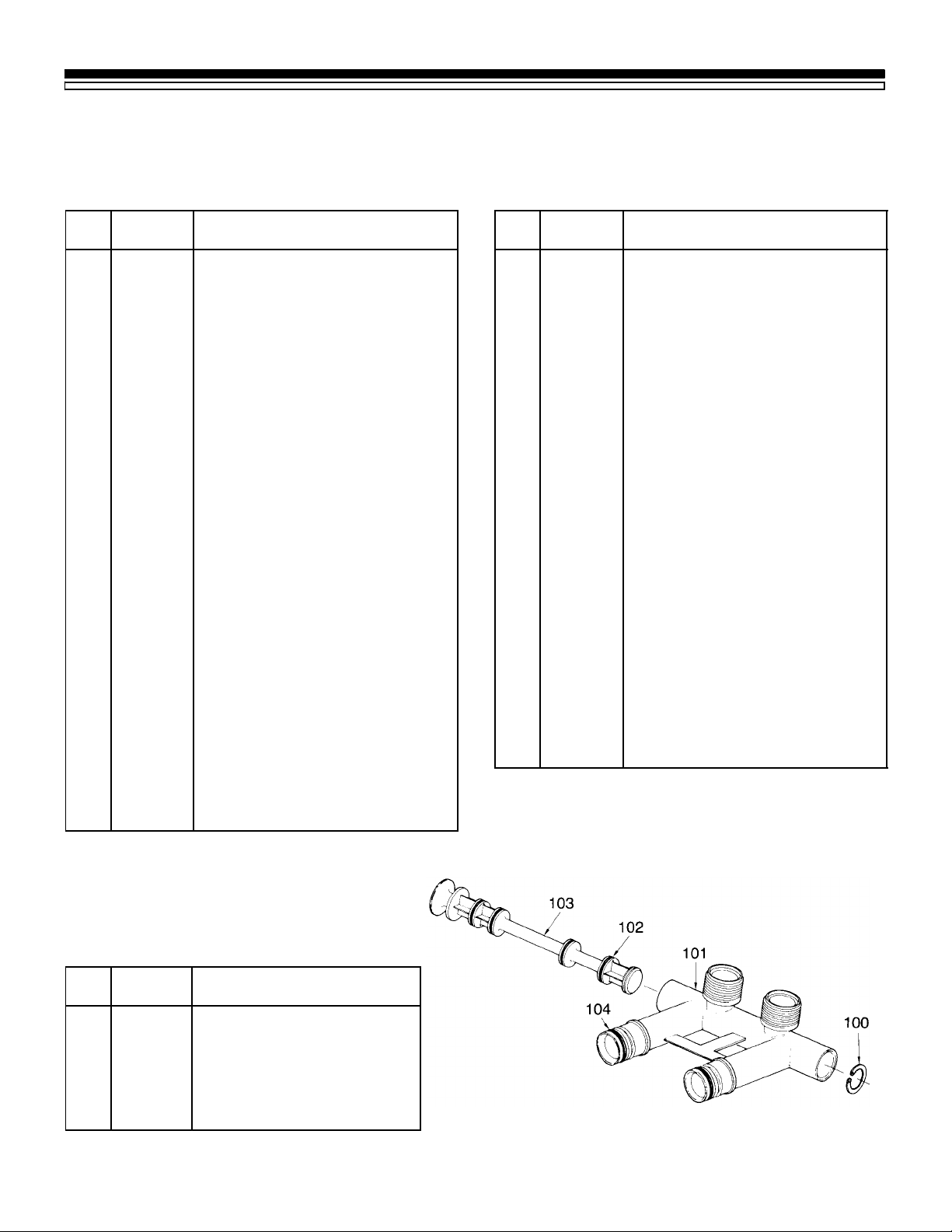
BYPASS INSTALLATION VALVE
MODEL NO. 625.34372
KEY
NO.
100 0502206 Retainer Ring
101 7129863 Bypass Body
102 7105013 O-Ring, 13/16 x 1 (4 req.)
103 7130911 Stem
104 7170288 O-Ring, 15/16 x 1-3/16 (2 req.)
z 42-3437 Bypass Valve (Complete) ¡
PART
NUMBER
DESCRIPTION
35
Page 36

OWNERS
MANUAL
MODEL NO.
625.348321
The model number of
your water softener is
found on the rating decal. This decal is on the
rim, under the saltcover.
When requesting service
or ordering parts, always
provide the following information:
z Product T ype
z Model Number
z Part Number
z Part Description
SOLID STATE
WATER SOFTENER
For the repair or replacement parts you need
Call 7 am -- 7 pm, 7 days a week
1 -- 800 -- 366 -- PART
(1 -- 800 -- 366 -- 7278)
For in--home major brand repair service
Call 24 hours a day, 7 days a week
1 -- 800 -- 4 -- REPAIR
(1 -- 800 -- 473 -- 7247)
For the location of a
Sears Repair Service Center in your area
Call 24 hours a day, 7 days a week
1 -- 800 -- 488 -- 1222
For information on purchasing a Sears
Maintenance Agreement, or to inquire
about an existing Agreement
Call 9 am -- 5 pm, Monday -- Saturday
1 -- 800 -- 827 -- 6655
REPAIR SERVICES
REPAIR SERVICES
America’s Repair Specialists
Sears, Roebuck and Co., Hoffman Estates, IL 60179 U.S.A.
7199012 ( 3/00 )
 Loading...