

Kenmore 5871656583, 5871656581, 5871656580, 5871648581 Owner’s Manual
Do-It-Yourself
REPAIR
for
AUTOMATIC DISHWASHERS
Easy-to-follow step-by-step repair
procedures and illustrations
Sold by Sears, Roebuck and Co, Chicago, IL 60684
i
22/587
.... _ _ _'r_-=:_- ,"_'_¸
We Service Wh_,t We Sell
Wherever you live, you may be
assured that there is a Sears
Service Organization as near as
your telephone.
The Technical Training Centers
pictured are staffed by the
finest, most capable Technical
Instructors we can find. In turn,
the Technicians in your local
Sears Service Organiz_ion have
in all probability been _rained in
one of these schools.
If ever you need us -- we're
available.
You Can Count On Us,
No part of this book may be reproduced
without the written permission of
Sears. Roebuclc and Co
_ Copyright 1981 by Se_rs, Roebuck
and Co
[Sears t
WHEN SEARS PEOPLE SAY, "WE SERVICE WHAT WE SELL." THEY MEAN IT,
When you get your appliance from Sears, Roebuck and Con, you get something
• nobody else can give you - Sears service. Many families who've been around hate to
buy even a toaster anywhere else.
Every month, about 400,000 Americans change jobs and move to other towns or
states. Many more are transferred by their compames, Families on the way up should
be prepared for moves around the cotJntry_
One important way to prepare_° take a tip from the military who really have to move
around the country_ Buy your appliances from Sears.
Suppose you live in Denver and you're moving to Bay Shore, NX, As soon as you and
the moving van arrive, all you have to do is call your Bay Shore Sears store and they'll
schedule a technician to hook up your Sears appliances.
"We service what we sell." To back up this slogan, Sears has thousands of service
trucks, logging millions of miles each yean
Is it worth it? Ask anyone who's ever had to move a family - around the country or
around the corner. Sears is nationwide.
For handy reference, use this space for
your nearest Sears Service Phone Nurnber_
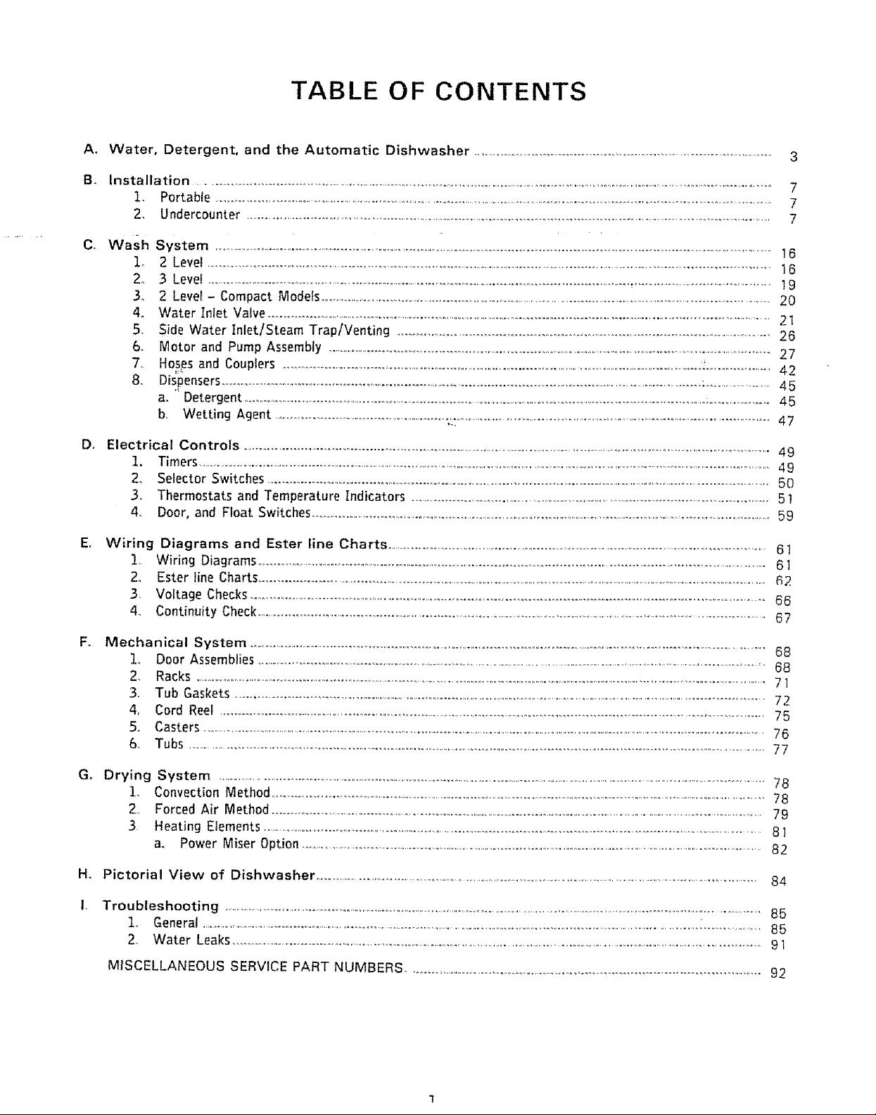
TABLE OF CONTENTS
A÷
Water, Detergent, and the Automatic Dishwasher ................................................................................................ 3
B_
Installation ...........................................................................................................................................................................................................
,
Portable ..........................................................................................................................................................................................
2,
Undercounter ....................................................................................................................................................................................
C_
Wash System ....................................................................................................................................................................................................16
I_ 2 Level .....................................................................................................................................................................................................16
2, 3 Level .........................................................................................................................................,......................................................19
3. 2 Level - Compact Modeis ...................................................................................................................................................................20
4. Water Inlet Valve.............................................................................................................................................................................21
5, Side Water Inlet/Steam Trap/Venting ....................................................................................................................................26
6. Motor and Pump Assembly .........................................................................................................................................................................27
7. Hos_sand Couplers ......................................................................................................................................................._:.................. 42
8. Dispensers...................................................................................................................................................................:........................45
a. ' Detergent ...................................................................................................................................................................................:,.................. 45
b. Wetting Agent ........................................................._,:................................................................................................................47
D,
Electrical Controls .............................................................................................................................................................................................49
1. Timers .......................................................................................................................................................................................................................................49
2. SelectorSwitches..........................................................................................................................................................................................50
34 Thermostats and Temperature Indicators .........................................................................................................................51
4. Door,and FloatSwitches..........................................................................................................................................................................59
7
7
7
Er
Wiring Diagrams and Ester line Charts ............................................................................................................................................61
i Wiring Diagrams .........................................................................................................................................................................................61
2. Ester line Charts...................................................................................................................................................................................................R2
3 Voltage Checks.................................................................................................................................................................................66
4. ContinuityCheck.........................................................................................................................................................................................67
Fo Mechanical System ..................................................................................................................................................................................68
!, Door Assemblies ....................................................................................................................................................................................................68
2_ Racks ...............................................................................................................................................................................................................................71
3. Tub Gaskets ....................................................................................................................................................................................................72
& Cord Reel ......................................................................................................................................................................................................75
5,, Casters ..........................................................................................................................................................................................................................76
6. Tubs ........................................................................................................................................................................................................77
G. Drying System ....................................................................................................................................................................................................................78
1_ Convection Method..........................................................................................................................................................................................78
2, Forced Air Method...............................................................................................................................................................................79
3, Heating Elements .....................................................................................................................................................................................8]
a. Power Miser Option .....................................................................................................................................................................82
H, Pictorial View of Dishwasher ...........................................................................................................................................................84
Troubleshooting .........................................................................................................................................................................................................85
1, General ....................................................................................................................................................................................................85
2,, Water Leaks......................................................................................................................................................................................................91
MISCELLANEOUS SERVICE PART NUMBERS ......................................................................................................................92
INTRODUCTION
This service manual is designed to provide you with a basic knowledge of the operation
of your Kenmore Dishwasher.
It was not designed to cover a specific model, but covers, in detail, the repa!r of most
components used on any model. The production of a service manual for each individual
model is not practical because of the excessive duplication that would resutL
Thorough study of this manual will provide a good working knowledge of the compo-
,nents that may be used within a Kenmore Dishwasher,. Application of this knowledge
to a specific dishwasher should make repair relatively simple.
Included in this manual are installation instructions and service procedures.
The importance of proper installation of any appliance cannot be overstressed. Our
experience indicates that incorrect installation is a major cause of unsatisfactory
product performance.
CAUTION - PLEASE NOTE
Sears, Roebuck and Co. assumes no responsibility for any repairs made on our products
by anyone other than our own Service Technicians,
Replacement of the dishwasher tub should be performed only by a qualified technician°
It is recommended that you contact your nearest Service Department for this service.
As a safety precaution, ALWAYS disconnect electrical power from the dishwasher
before attempting to make any repairs_
A. WATER, DETERGENT AND THE AUTOMATIC
DISHWASHER
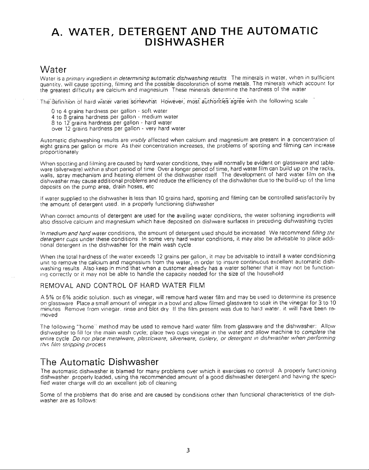
Water
Water is a primary ingredient in determining automatic dishwashing result5 The minerafs in water, when in sufficient
quantity, wilt cause spotting, filming and the possible discoloration of some metals. The minerals which account tot
the greatest difficulty are calcium and magnesium These minerals delermine the hardness ol the water
Theaefin[tibn of hard _ate_: varies s6h_ewP;at However[ m6s{-a_Jthor[fies a'gree G4th the following scaie "
0 to 4 grains hardness per gatlon - soft water
4 to 8 grains hardness per gallon - medium water
8 to 12 grains hardness per gallon - hard water
over 12 grains hardness per gallon - very hard water
Automatic dishwashing results are v_stb/y affected when calcium and magnesium are present in a concentration ot
eight grains per gallon ol more As their concentration increases, the problems of spotting and filming can increase
proportionately
When spotting and filming are caused by hard water conditions, they wilt normally be evident on glassware and table-
ware (silverware! within a short period of time Over a longer period of time, hard water film can build up on the racl.:s,
walls, spray mechanism and heating element of the dishwasher itself The development of hard wa'ter film on the
dishwasher may cause additional problems and reduce the efficiency of the dishw_tsher due to the build-up of the time
deposits on the pump area, drain hoses, etc
If water supplied to the dishwasher is less than !0 grains hard, spotting and filming can be controlled satisfactorily by
the amount of detergent used. in a properly functioning dishwasher
When correct amounts of detergent are used for the availing water conditions, the water softening ingredients wilt
also dissolve calcium and magnesium which have deposited on dishware surfaces in preceding dishwashing cycles
In medium and hard water conditions, the amount of detergent used should be increased We recommend fdhng the
detergent cups under these conditions In some very hard water conditions, it may also be advisable to place addi-
tional detergent in the dishwasher for the main wash cycle
When the total hardness of the water exceeds 12 grains per gallon, it may be advisable to install a water conditioning
unit to remove the catcium and magnesium from the water, in order to insure continuous excellent automatic dish-
washing results Also keep in mind that when a customer already has a water softener that it may not be function-
_nq correctly or it may not be able to handle the capacity needed for the size of the household
REMOVAL AND CONTROL OF HARD WATER FILM
A 5% or 6% acidic solution, such as vinegar, will remove hard water film and may be used lo determine its presence
on glassware Place a small amount of vinegar in a bowl and allow filmed glassware to soak in the vinegar for 3 to 10
minutes Remove from vinegar, rinse and blot dry tf the film present was due to hard water, it will have been re-
moved
The following "home" method may be used to remove hard water film from glassware and the dishwasher: Allow
dishwasher to fill for the main wash cycle; place two cups vinegar in the water and allow machine 1o complete the
entire cycle Do not place metalware, plasricvvare, silverware, cutlery, or detergent m dJsh_c'asher when performing
[h_ fffm _tnpping prodes_
The Automatic Dishwasher
The automatic dishwasher is blamed for many problems over which it exercises no control A properly funclioning
dishwasher, properly loaded, using the recommended amount of a good dishwasl_er detergent and having the speci*
fled water charge will do an excellent job of cleaning
Some of the problems that do arise and are caused by conditions other than functional characleristics of the dish*
washer are as follows:
Sudsing- You are familiar with the mountains of suds that result from using the wrong detergent in an automatic
washer A similar problem in an automatic dishwasher can be caused by using improper detergents, using solid
jet dry. a leaking wetting agent dispenser or excessively tow or high water temperature A complaint of poor
cleaning of dishware may accompany this problem Sudsing leaks in a dishwasher will usually occur at the door
gasket or the blower housing On hard to find leaks, suspect sudsing and check the following:
Use a fresh detergent made especcal/y for automatic d_shwashing. Such detergents are labeled on each container
for automatic or electric dishwashing When in doubt, consult the Owner's Manual; i1 contains the recommended
detergents, or use recognizable major brands
Water temperature recommended on most detergent packages is 140° if water temperature is extremely low
(120 °) or extremely high (180°}, then sudsing will surely occur For best results from detergent and wetting agent
liquid, water temperature should be between t40 ° - 150°F Solid jet dry should be avoided except if you should
choose to place the jet dry in dishwasher for the final rinse only
Hand pre-washing of dishware with .Joy or other such dishwashing liquids or soaps prior 1o loading can cause ex-
cessive sudsing since this liquid may not be thoroughly rinsed away and, ,when agitated in the dishwasher, can
cause sudsing
A malfunctioning of the wetting agent dispenser mechanism which would allow excessive amounts of liquid jet
dq,' to be released in the rinse or wash may also cause excessive sudsing Each injection of wetting agent liquid
should be approximately 8cc
Etching - Etching of glassware is the result of soft glass and an alkaline compound. The surface of the glass has
actually been destroyed and no amount of rubbing can restore the glassware to its original state
A quick check for etching can be made by scratching the surface of the glass with a pin If the "stain" or "spott-
ing" (white film) can be removed, the condition is an undesirable film but not etching
Permanent etching of glassware can in no way be caused by the operation of the dishwasher The dishwasher can
only be a contributor to the problem if it is not properly circulating the water charge
Make sure the dishwasher is operating normally and there is an adequate supply (volume) of water to insure a good
fill each time Check to be certain the water is circulating and the detergent is fresh
There are several factors which cause or contribute to permanent (etching) staining
1 Extremely hot water
2 Excessive use of detergent for water condition
3 The water ts soft (0 to 4 grains hard, either naturally or thru a softener)
4 Composition [mineral makeup] of water
5 Composition of the glasses themselves
Softened water is more detrimental than naturally soft water We do not imply that the water softener be re,-
moved There may be a definite need for a softener
We can elfectively control only two of the above factors; wa[er temperature and amount of detergent.
We recommend when etching is encountered that water temperature be set no higher than !40°; and a reduction
in the amount of detergent used, consistent with good dishvvashing results One tablespoon per detergent cup
may be adequate
This may not completely eliminate etching, but it wilt help 1o slow down the process of etching of glassware
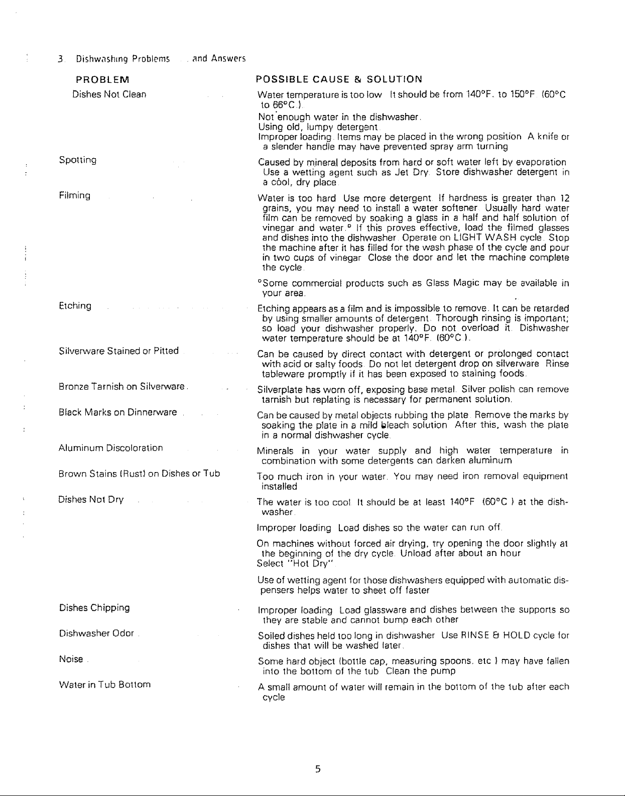
3 DishwashmgProblems andAnswers
PROBLEM
DishesNotClean
Spotting
Filming
Etching ...........
Silverware Stained or Pitted
Bronze Tarnish on Silverware
Black Marks on Dinnerware
Aluminum Discoloration
Brown Stains (Rust) on Dishes or Tub
Dishes Not Dry
POSSIBLE CAUSE & SOLUTION
Water temperature is too low It should be from t40°Fo to t50°F (60°C
to 66°C,)
Not enough water in the dishwasher
Using old, lumpy detergent
Improper loading Items may be placed in the wrong position A knife or
a slender handle may have prevented spray arm turning
Caused by minera! deposits from ha(d or soft water left by evaporation
Use a wetting agent such as Jet Dry Store dishwasher detergent in
a c0ol, dry place
Water is too hard Use more detergent tf hardness is greater than ]2
grains, you may need to install a water softener Usually hard water
film can be removed by soaking a glass in a half and half solution of
vinegar and water, ° If this proves effective, load the filmed glasses
and dishes into the dishwasher Operate on LIGHT WASH cycle Stop
the machine after it has filled for the wash phase of the cycle and pour
in two cups of vinegar Close the door and let the machine complete
the cycle
°Some commercial products such as Glass Magic may be avaifable in
your area
Etching appears as a film and is impossible to remove It can be retarded
by using smaller amounts of detergent Thorough rinsing is important;
so load your dishwasher properly. Do not overload it Dishwasher
water temperature should be at 140°F. (60°C),
Can be caused by direct contact with detergent or prolonged contact
with acid or salty foods Do not let detergent drop on silverwai'e Rinse
tableware promptly if it has been exposed to staining foods.
Silverplate has worn off, exposing base metal, Silver polish can remove
tarnish but replating is necessary for permanent solution
Can be caused by metal objects rubbing the plate Remove the marks by
soaking the plate in a mild Meach solution After this, wash the ptate
in a normal dishwasher cycle
Minerals in your water supply and high water temperature in
combination with some detergents can darken aluminum
Too much iron in your water You may need iron removal equipment
installed
The water is too cool It should be at least 140°F (60°C) at the dish-
washer
Improper loading Load dishes so the water can run off
On machines without forced air drying, try opening the door slightly at
the beginning of the dry cycle Unload after about an hour
Select "Hot Dry"
Use of wetting agent for those dishwashers equipped with automatic dis-
pensers helps water to sheet off faster
Dishes Chipping
Dishwasher Odor
Noise
Water in Tub Bottom
Improper loading Load glassware and dishes between the supports so
they are stable and cannot bump each other
Soiled dishes held too long in dishwasher Use RINSE 8 HOLD cycle for
dishes that will be washed later
Some hard object (bottle cap, measuring spoons, etc ) may have fallen
into the bottom of the tub Clean the pump
A small amount of water will remain in the boltom of the tub after each
cycle
CLEANINGMINERALDEPOSITSFROMPORCELAINSURFACES
Thefollowingprocedureissafeif theinstructionsarecarefullyfollowed
Manycomplaintsofporcelaindeleriorationhavebeentracedtoasurfacediscolorationduetothepresenceofiron,
manganeseorcalciuminthewa;ersupplyInareashavingahighmineralcontentinthewater,particularlyiron,
discolorationorstainscanusuallyberemovedbythefollowingmethod:
t UsewatersoftenerResinCleanerThiscompoundisavailablefromSearsPlumbingand Heating Department
2 Pour 8 ounces of the compound into the bottom of the tub
3 Fill the 2rid wash detergent cup with dishwasher detergent and close the cup
4 Select a normal cycle - must have 2 washes and 4 rinses
5 Allow the dishwasher to complete all washes and rinses It is not necessary to complete the dry cycle
6 DO NOT place dinnerware or silverware in the dishwasher during the cleaning operation,
CA UT/ON:
Because of the obnoxious odor of the cleaner in solution - Do Not open the dishwasher
door until the completion of the last rinse°
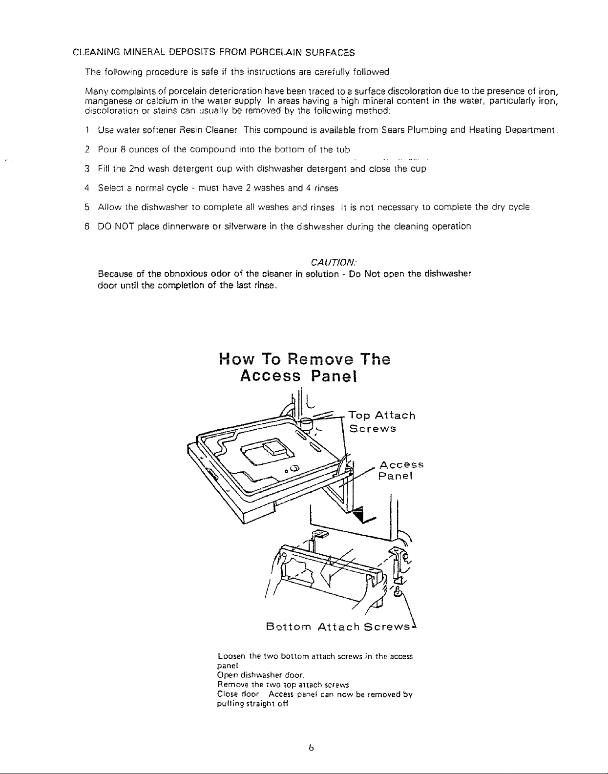
How To Remove The
Access Panel
Attach
Screws
/
Bottom
Access
Panel
Loosen the two bottom attach screws in the access
pane_
Open dishwasher door,
Remove the two top attach screws
Close door Access panel can now be removed by
puIling straight off
B. INSTALLATION
Portable Dishwasher
Hot Water Connections - Portable Dishwasher
I. Attach the AERATOR ADAPTOR furnished with the dishwasherto the sink faucet.
2. Check the power outlet.
A. Will it take the three-prong plug on the power cord?
B. Is the outlet grounded?
CHECKING POWER OUTLET
The dishwasherwilloperateon regularhousecurrent,Do notuseanyotherapplianceon thesame circuit,Use a circuit
withatJeasta 15 Ampere,butnotmore thana 20 Ampere fuse.The dishwasherpowercordisathreeprongtypeand
must be pluggedintoa threeholegroundedoutlet°The dishwasherMUST BE GROUNDED forsafeoperation,,Do not,
underanycircumstances,removethepowersupplycordgroundprong°
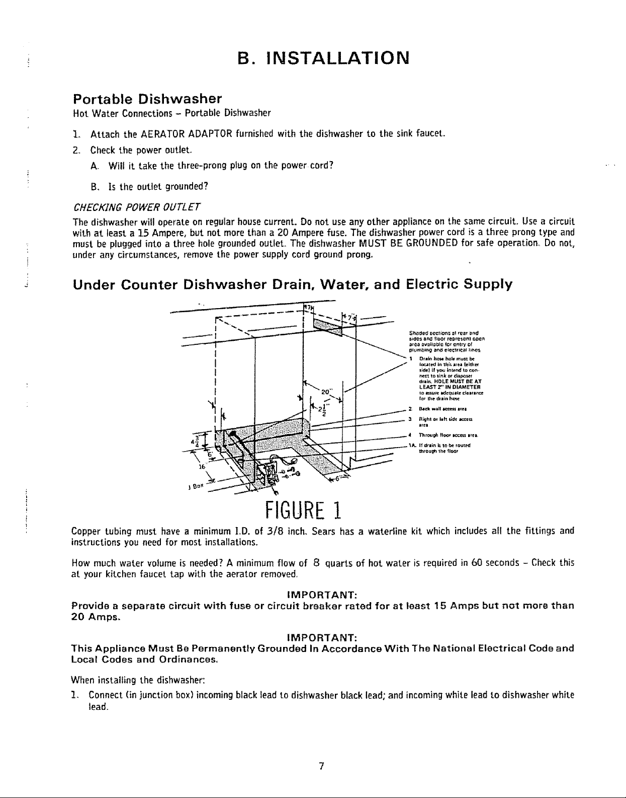
Under Counter Dishwasher Drain, Water, and Electric Supply
I
I
I
!
I
I
16
FIGURE!
Copper tubing must have a minimum I,D. of 3/8 inch. Sears has a waterline kit which includes all the fittings and
instructions you need for mostinstallations.
How much water volume is needed? A minimum flow of 8 quarts of hot water is requiredin 60 seconds - Check this
at your kitchen faucet tap with the aerator removed.
IMPORTANT:
Provide a separate circuit with fuse or circuit breaker rated for at least 15 Amps but not more than
20 Amps.
IMPORTANT:
This Appliance Must Be Permanently Grounded In Accordance With The National Electrical Code and
Local Codes and Ordinances°
When installing the dishwasher:
I. Connect (in junction box) incoming black lead to dishwasher black lead; and incomingwhite lead to dishwasher white
lead.
2 Attach grounding wire to green grounding screw
CAUTION:
The joining of aluminum building wire to stranded copper wire leads on the dishwasher involves special
problems It should be done only by qualified personnel using material recognized by U/L (or CSA) as suitable
DRAIN. Improper!y installed drain hoses can kink and result in poor washability or failure of the dishwasher to
drain Do not use the drain hose supplied with the dishwasher for the water supply line It is not a reinforced hose
and wil! burst under water line pressure
NOTE,"
A properly operating dzshwasher will have approxtma_e/y .2 cups of clean water rematmng in [he [ub at the com-
pletion .of [he cycle. .........
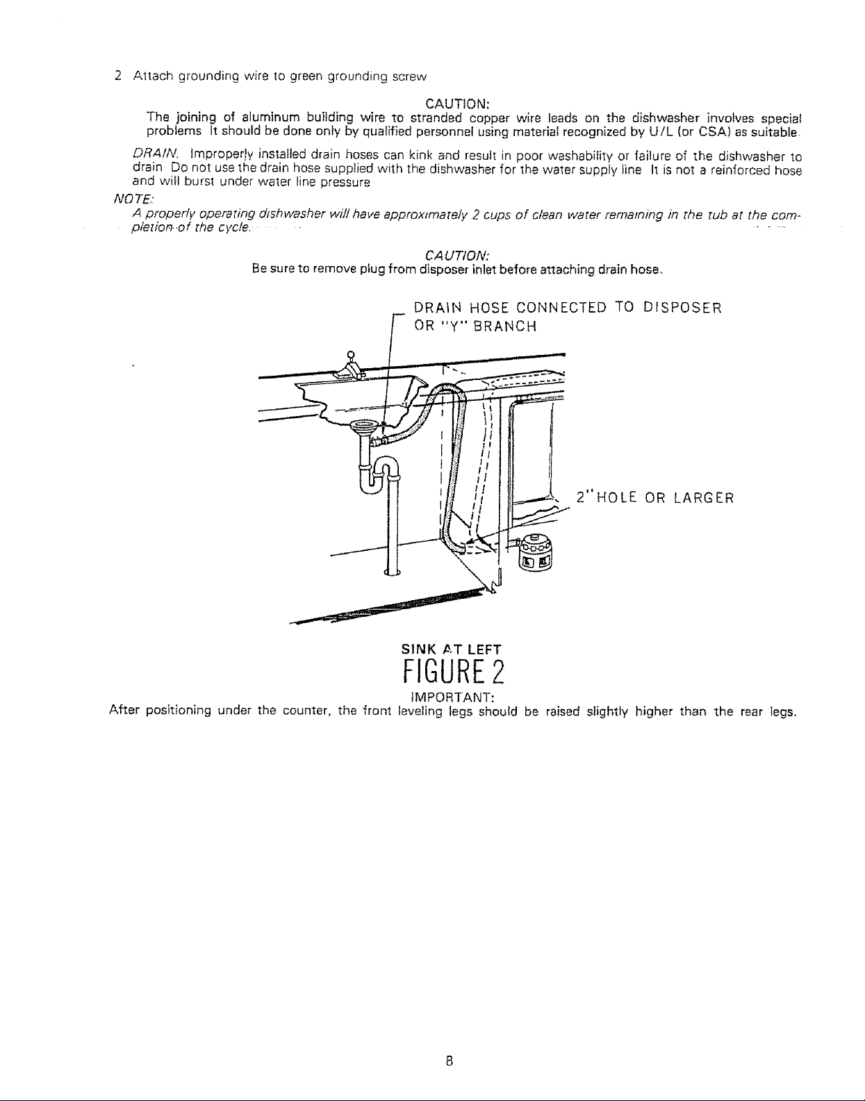
CA UTION:
Be sure to remove plug from disposer inlet before attaching drain hose,
DRAIN HOSE CONNECTED TO DISPOSER
OR "y" BRANCH
2"HOLE OR LARGER
SINK X,,T LEFT
FIGURE2
iMPORTANT:
After positioning under the counter, the front leveling legs should be raised slightly higher than the rear legs.
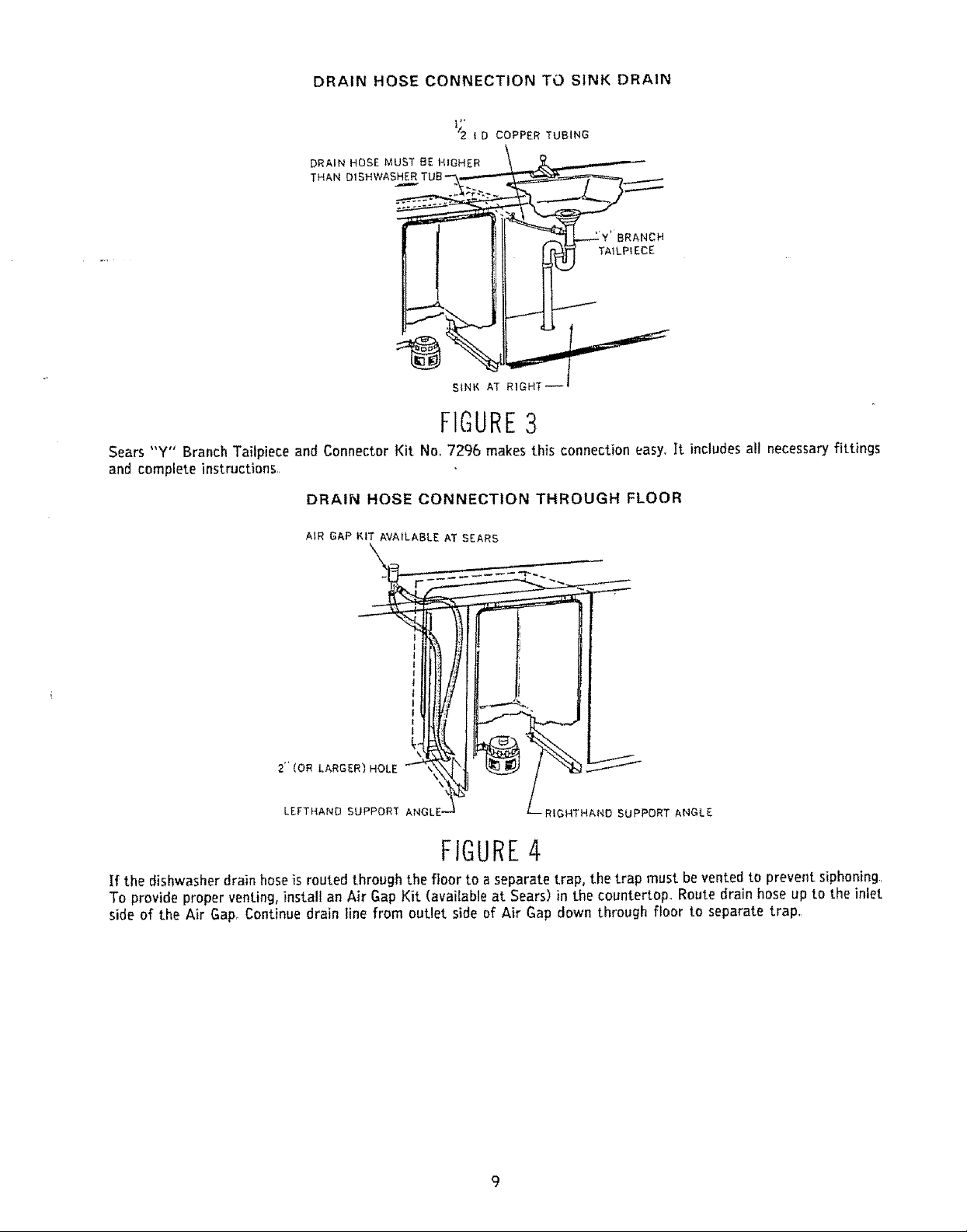
DRAINHOSECONNECTIONTOSINKDRAIN
/2 ! O COPPER TUBING
DRAIN HOSE MUST BE _tGHER
THAN DIS
3RANCH
TAILPIECE
S{NF, AT RIGHT
FIGURE3
Sears "Y" Branch Tailpiece and Connector Kit No, 729b makes this connection easy, It includes a!l necessary fittings
and complete instructions,
DRAIN HOSE CONNECTION THROUGH FLOOR
AIR GAP KIT AVAILABLE AT SEARS
2"{OR LARGER) HOLE
LEFTNAND SUPPORT
\
\
RIGHTHAND SUPPORT ANGLE
FIGURE4
If the dishwasher drain hose is routed through the floor to a separate trap, the trap must be vented to prevent siphoning,
To provide proper venting, install an Air Gap Kit (available at Sears) in the countertop, Route drain hose up to the inlet
side of the Air Gap, Continue drain line from outlet side of Air Gap down through floor to separate trap,
Models Equipped With Installation Module
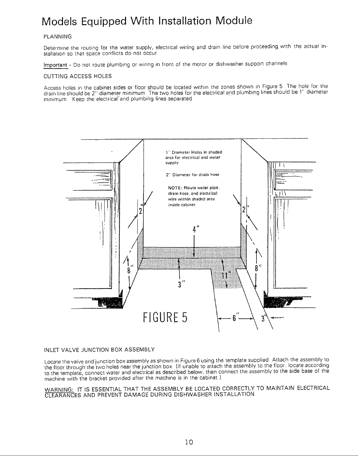
PLANNING
Determine the rouling for the water supply, eleclrical wiring and drain line before proceeding with the actual in-
sin!tarpon so that space conflicts do not occur
Important - Do no1 [oute ptumbing or wiring in front of the motor or dishwasher support channels
CUTTING ACCESS HOLES
Access holes in the cabinet sides or floor should be located within the zones shown in Figure 5 The hole for lhe
drain lineshould be 2" diameter minimum The two holes for the electrical and plumbing lines should be 1" d,ameter
minimum Keep the electricaland plumbing lines separated
fl!:.....
FIGURE5
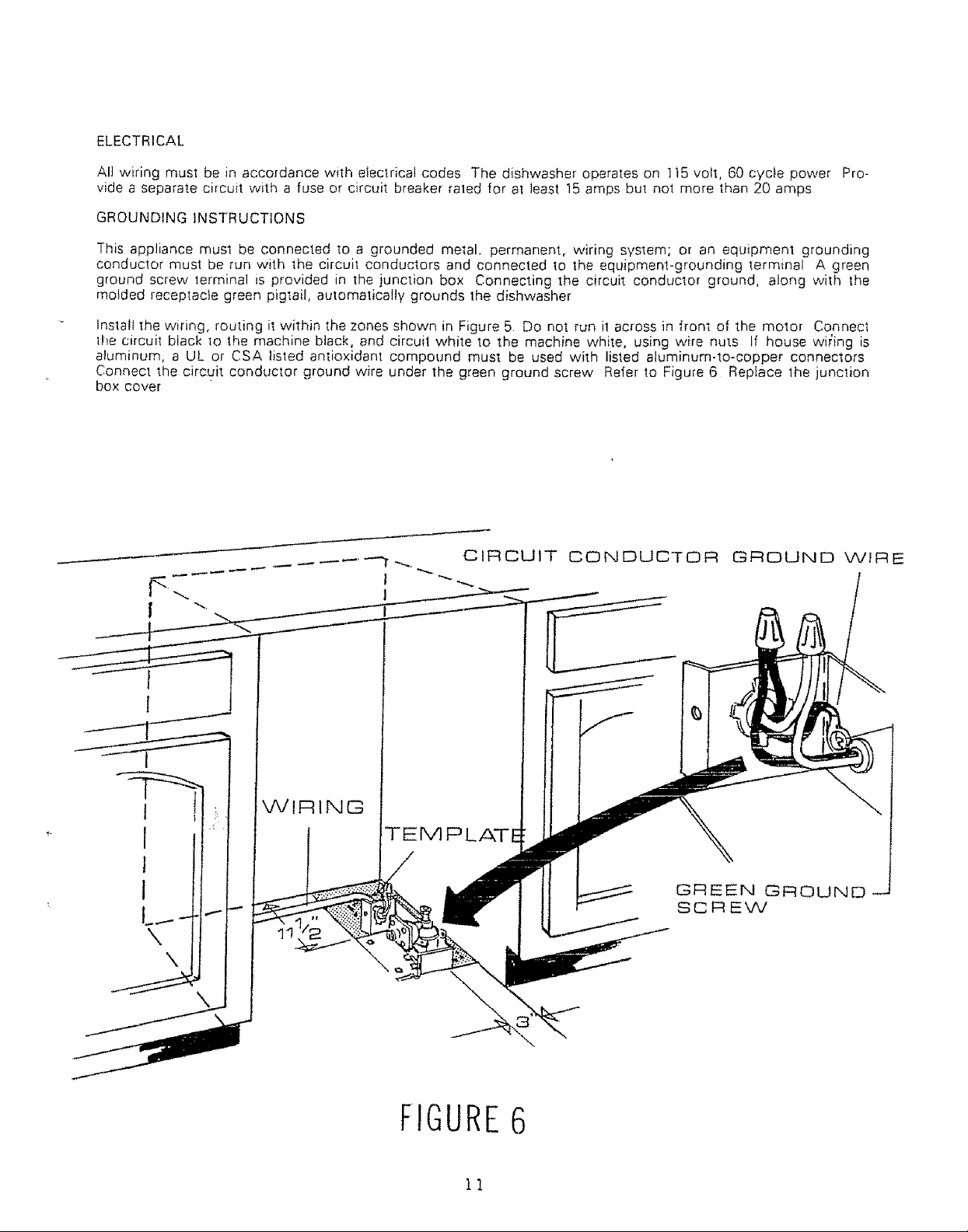
INLET VALVE ,JUNCTION BOX ASSEMBLY
Locale the valve and junction box assembly as shown in Figure 6 using the template supplied Attach the assembly 1o
the floor through 1he two holes near the junction box (If unable to atlach the assembly to the floor, locale according
to the template, connect water and electrical as described below, then connect the assembly to the side base ol the
machine with the bracket provided after the machine is in the cabinet )
WARNING: IT IS ESSENTIAL THAT THE ASSEMBLY BE LOCATED CORRECTLY TO MAINTAIN ELECTRICAL
CLEARANCES AND PREVENT DAMAGE DURING DISHWASHER INSTALLATION
t0
ELECTRICAL
All wiring must be in accordance with electrical codes The dishwasher operates on !15 volt, 60 cycle power Pro-
vide a separate circuit with a fuse or circuit breaker rated for at least 15 amps bul not more than 20 amps
GROUND1NGINSTRUCTIONS
This appliance must be connected to a grounded metal, permanent, wiring system; or an equipment grounding
conductor must be run with the circui_ conductors and connected to the equipment-grounding terminal A green
ground screw terminal is provided in The junction box Connecting the circuit conductor ground, along with the
molded receptacfe green pigtail, automatically grounds 1he dishwasher
install the wiring, routing it within the zones shown in Figure 5 Do not run i! across in front of the motor Connect
lhe circuit black 1o the machine black, and circuil white to the machine white, using wire nuts If house wi_ing is
aluminum, a UL or CSA listed antioxidant compound must be used with listed aluminum-to-copper connectors
Connect the circuit conductor ground wire under the green ground screw Refer to Figure 6 Replace the junction
box cover
CIRCUIT CONDUCTOR GROUND WIRE
¢7IRING
GREEN GROUND
SCREW
\
FIGURE6
11
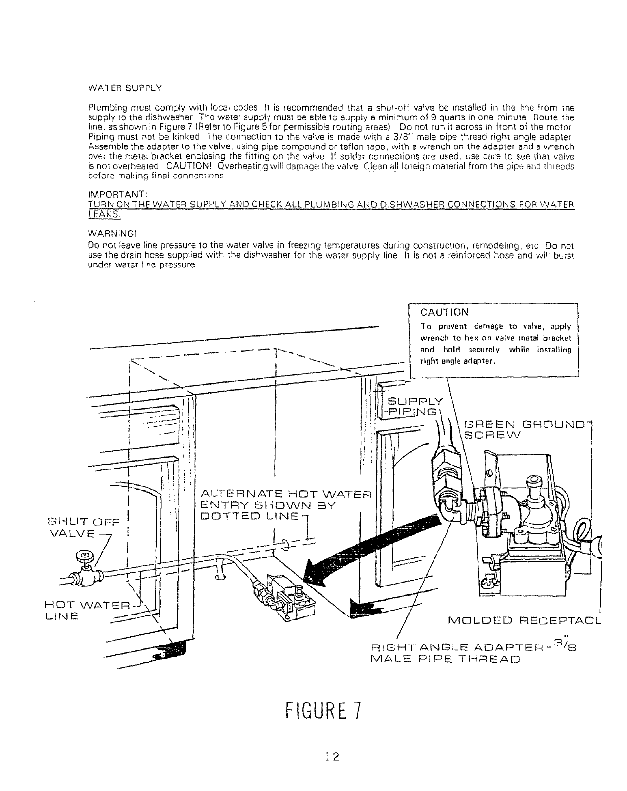
WA] ER SUPPLY
Plumbing must comply with local codes It is recommended that a shul-off valve be installed in the line from the
supply to the dishwasher The water supply must be able lo supply a minimum of 9 quarts in one minute Route the
Ime, as shown in Figure 7 (Refer to Figure 5 for permissible routing areas) Do not run it across in front of the motor
Piping must not be kinked The connection to the valve is made with a 3/8" male pipe thread right angle adapter
Assemble the adapter to the valve, using pipe compound or teflon tape, with a wrench on the adapler and a wrench
over the metal bracket enclosing the fitting on the valve If solder connections are used. use care to see that valve
is not overhea!ed CAUTION! Qverheating witl da0qage the valve Clean all ioreign matedal from the pipe and threads
before maldng final connections
IMPORTANT:
TURN ON THE WATER SUPPLY AND CHECK ALL PLUMBING AIqD DISHWASHER CONNECTIONS FOR WATER
LEAKS.
WARNING!
Do not have line pressure Io the water valve in freezing temperatures during construction, remodeling, elc Do not
use the drain hose supplied with the dishwasher for the water supply line It is not a reinforced hose and will burst
under water line pressure
CAUTION
I
To prevent damage to valve,apply
wrench to hex on valvemetal bracket
and hold securely while installing
rigflt angle adapter,,
SHUT OFF
VA LV E
HOT WATE
LINE
SUPPLY
I
I
ALTERNATE HOT WATER
ENTRY SHOWN BY
DDT_ED LINE
_REEN GROUND"
SCREW
\
MOLDED REO EPTACL
/
RIGHT ANGLE ADAPTER -3/8
MALE PIPE THREAD
FIGURE7
12
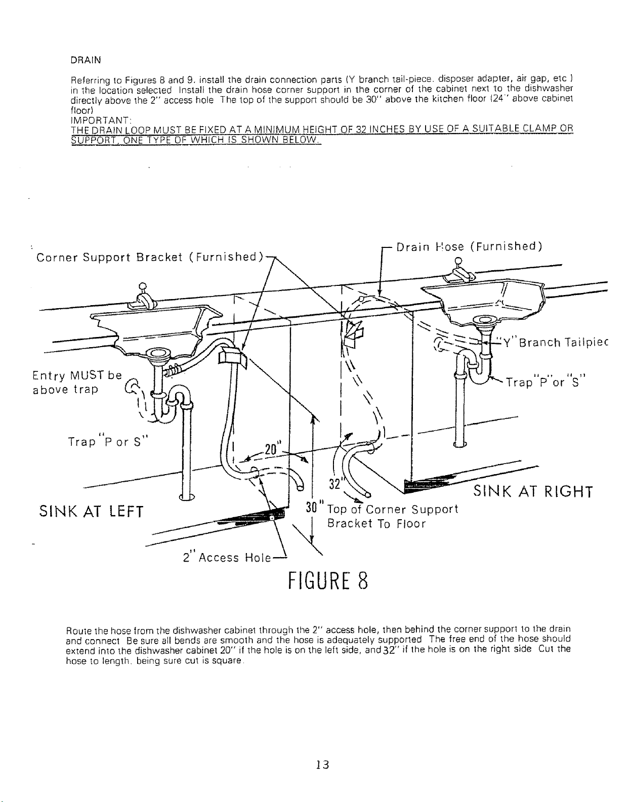
DRAIN
Referring to Figures 8 and 9. install the drain connection parts (Y branch tail-piece, disposer adapter, air gap, etc )
in the location selected Instali the drain hose corner support in the corner of the cabinet next to the dishwasher
directly above the 2" access hole The top of the support should be 30" above the kitchen floor 124-' above cabinet
floor)
IMPORTANT:
THE DRA!N LOOP MUST BE FIXED ATA lvl!N,!MUM HEIGHT,,QF,,,32 INCHES BY USE OF A SUITABLE CLAMP OR
SUPPORT._ONE -IYPE OF WHICH IS SHOWN BELOW.
Corner Support Bracket (Furnished
Drain Hose (Furnished)
"'Branch Tailpie(:
Entry MUST be
above trap _1_ t
Trap P or S
SINK AT LEFT
Route the hose from the dishwasher cabinet through 1he 2" access hole, then behind the corner support to the drain
and connect Be sure all bends are smooth and the hose is adequately supported The free end of the hose should
extend into the dishwasher cabinet 20" if the hole is on the left side, and32" if the hole is on the right side Cut the
hose to length, being sure cut is square
\
\
Trap P or S
SINK AT RIGHT
3O"Top of Corner Support
Bracket To Floor
2 Access Hole--
FIGURE8
13
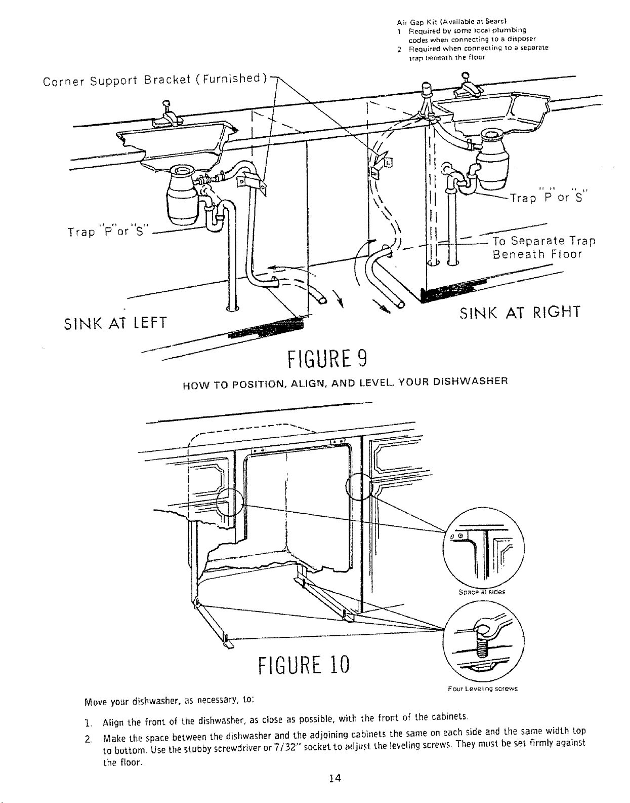
Corner Support Bracket (Furnished)
Trap P or S
Air Gap Kit {Available at Sears}
1 Required by some local plumbing
codes when connecting 10 a disposer
2 Required when connecting 7o a separate
Irap benea'lh 1he floor
To Separate Trap
Beneath Floor
SINK AI LEFT
\
SINK AT RIGHT
FIGURE9
HOW TO POSITION, ALIGN, AND LEVEL, YOUR DISHWASHER
FIGUREIO
Move your dishwasher, as necessary, to:
Align the front of the dishwasher, as close as possible, with the front of the cabinets,
2.
Make the space between the dishwasher and the adjoining cabinets the same on each side and the same width top
to bottom, Use the stubby screwdriver or 7/=32" socket to adjust the teveling screws, They must be set firmly against
Lhe floor,
14
F $oc_r anchori_g
with _' lag screw_
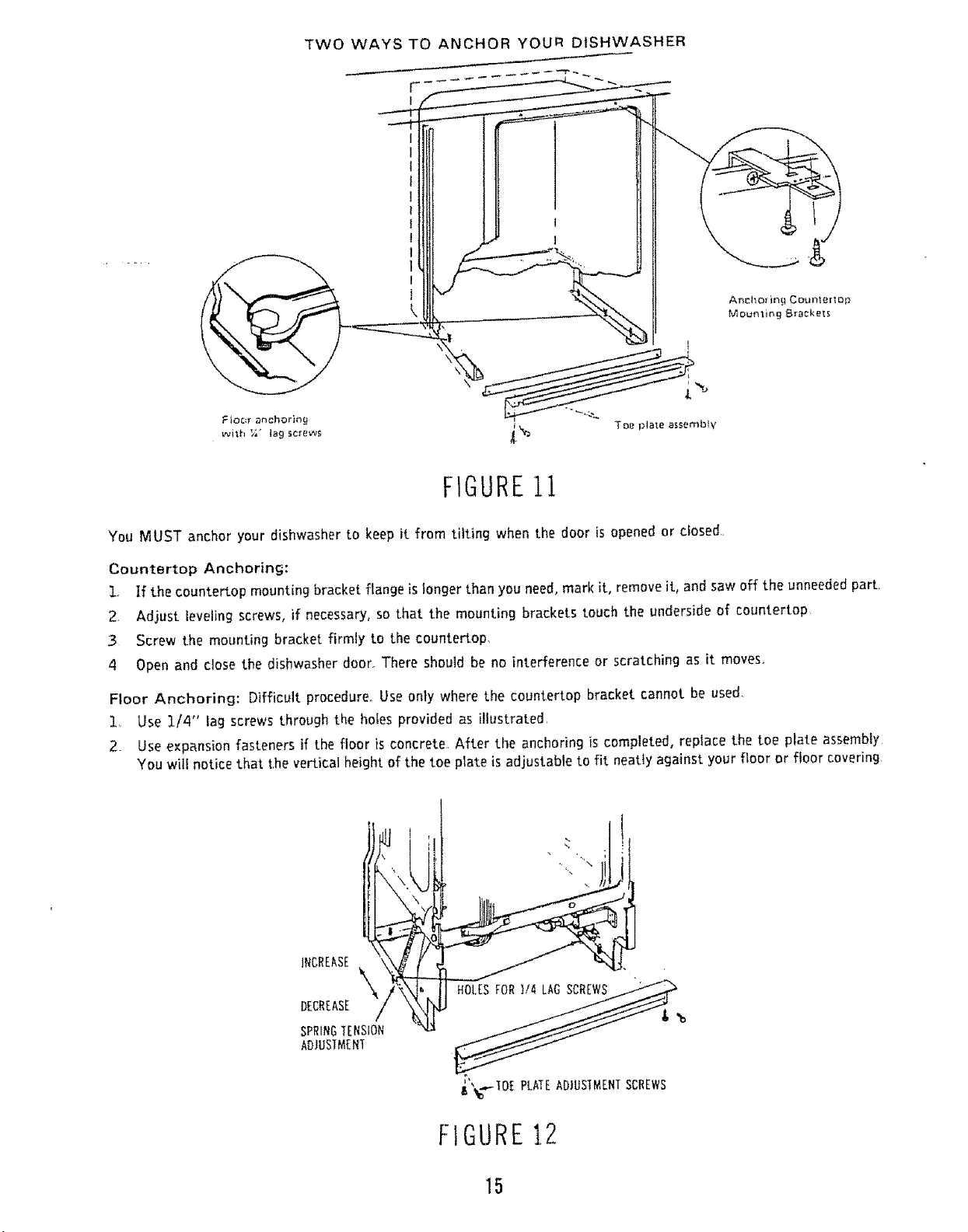
TWO WAYS TO ANCHOR YOUR DISHWASHER
_ Toe plate assembtv
FIGURE11
You MUST anchor your dishwasher to keep it from tilting when the door is opened or closed.
Countertop Anchoring:
1. If the countertop mounting bracket flange is }onger than you need, mark it, remove it, and saw off the unneeded part.
2, Adjust leveling screws, if necessary, so that the mounting brackets touch the underside of countertop
3 Screw the mounting bracket firmlyto the counter[op,
4 Open and dose the dishwasherdoor°There should be no interferenceor scratchingas itmoves,
Floor Anchoring: Difficult procedure. Use only where the countertop bracket cannot be used.
1 Use 1/4" lag screws through the holes provided as illustrated
2. Use expansion fasteners if the floor is concrete After the anchoring is completed, replace the toe plate assembly
You will notice that the vertical height of the toe plate is adjustable to fit neatly against your floor or floor covering
INCREASE
\
DECREASE
_"_-.,-_OEPLATEADJUS]MENTSCREWS
FIGURE12
15
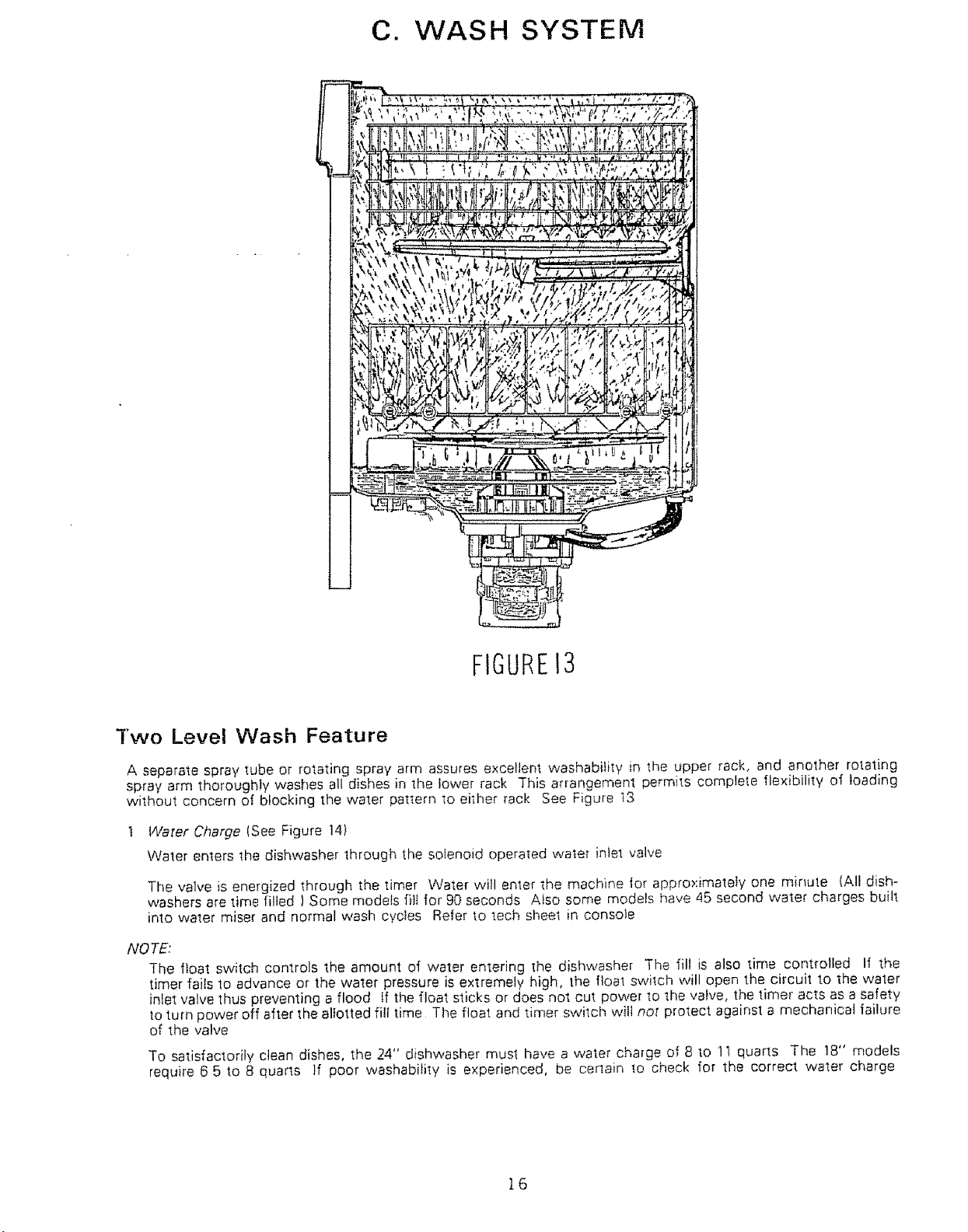
C. WJASH SYSTEM
FIGUREI3
Two Level Wash Feature
A separate spray tube or rotating spray arm assures excellent washability in the upper rack, and another rotating
spray arm thoroughly washes all dishes in the lower rack This arrangement permits complete flexibility of ioading
without concern of blocking the water pattern to el;her rack See Figure t3
Water Charge (See Figure 14)
Water enters the dishwasher through the solenoid operated water inlet valve
The valve is energized through the timer Water will enter the machine 1or approximately one minute (All dish-
washers are time filled ) Some models fill for 90 seconds Also some models have 45 second water charges built
into water miser and normal wash cycles Refer to tech sheet in console
NOTE:
The float switch controls the amount of water entering the dishwasher The fill is also time controlled If the
timer fails to advance or the water pressure is extremely high, the float switch will open the circuit to the water
inlet valve thus preventing a flood If the float sticks or does not cut power to the valve, the timer acts as a safety
_oturn power off after the allotted fill time The float and timer switch will not protect against a mechanical failure
of the valve
To satisfactorily clean dishes, the 24" dishwasher must have a water charge of 8 to 11 quarts The !8" models
require 6 5 to 8 quarts if poor washability is experienced, be certain to check for the correct water charge
16
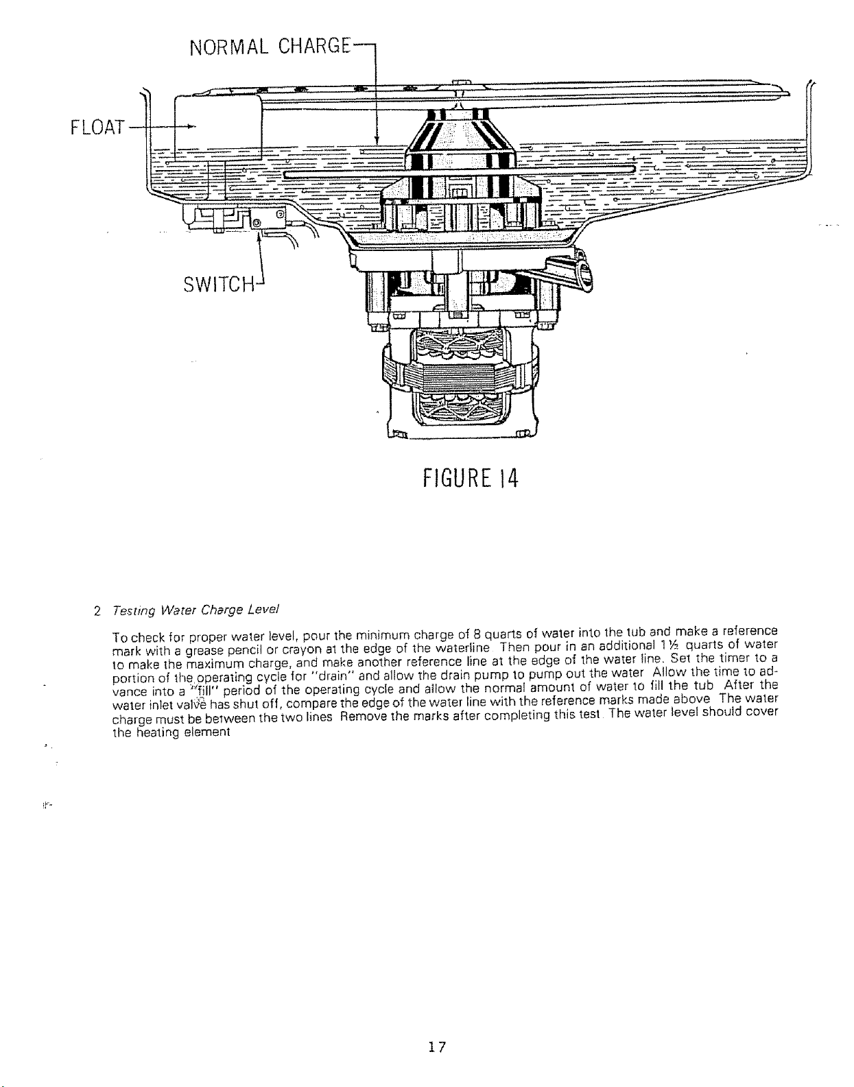
FLOAT
NORMAL
SWITCH
FIGURE14
2 Testing Water Charge Level
To check for proper water level, pour the minimum charge ol_8 quarts of water into the tub and make a reference
mark with a grease pencil or crayon at the edge of the waterline Then pour in an additional 1 Y_,quarts of water
to make the maximum charge, and make another reference line at the edge of the water line, Set the timer to a
portion of the operating cycle for "drain" and allow the drain pump to pump out the water Allow the time to ad-
vance into a )_;fill" period of the operating cycie and allow the normal amount of water to fill the tub After the
water inlet valge has shut off, compare the edge of the water line with the reference marks made above The water
charge must be belween the two lines Remove the marks after completing this test The water level should cover
tile heating element
17
ttttt
t t
FIGURE15
.
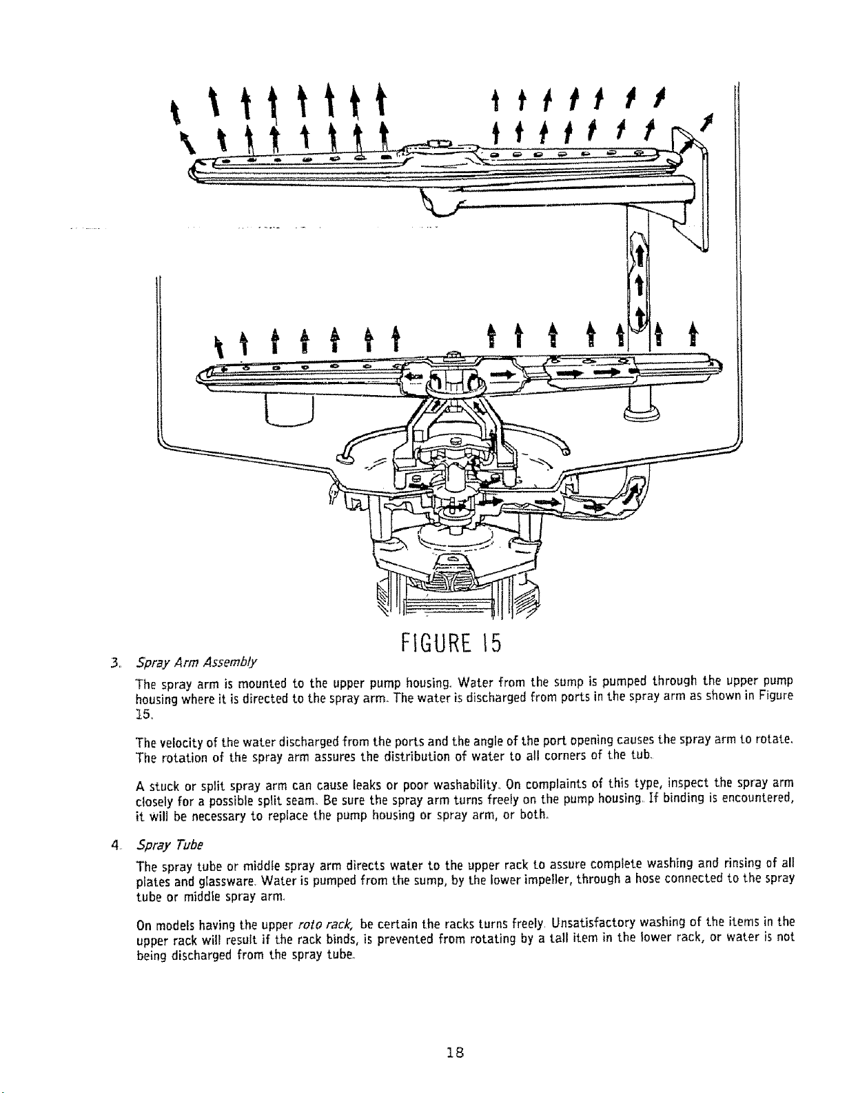
Spray Arm Assembly
The spray arm is mounted to the upper pump housing_Water from the sump is pumped through the upper pump
housingwhere it isdirected to the spray arm..The water is discharged from ports in the spray arm as shown in Figure
t5..
The velocityof the water discharged from the ports and the angle of the port opening causesthe spray arm to rotate.
The rotation of the spray arm assures the distribution of water to all corners of the tub,
A stuck or split spray arm can cause ieaks or poor washability. Oncomplaints of this type, inspect the spray arm
closely for a possible split seam. Be sure the spray arm turns freely on the pump housing. If binding is encountered,
it wilt be necessary to replace the pump housing or spray arm, or both°
_
5pray Tube
The spray tube or middle spray arm directswater to the upper rack to assure complete washing and rinsing of all
plates and glassware. Water ispumped from the sump, by the lower impeller, through a hoseconnected to the spray
tube or middle spray arm,
On models having the upper rolo rack, be certain the racks turns freely. Unsatisfactory washing of the items in the
upper rack will result if the rack binds, is prevented from rotating by a tall item in the lower rack, or water is not
being discharged from the spray tube..
18
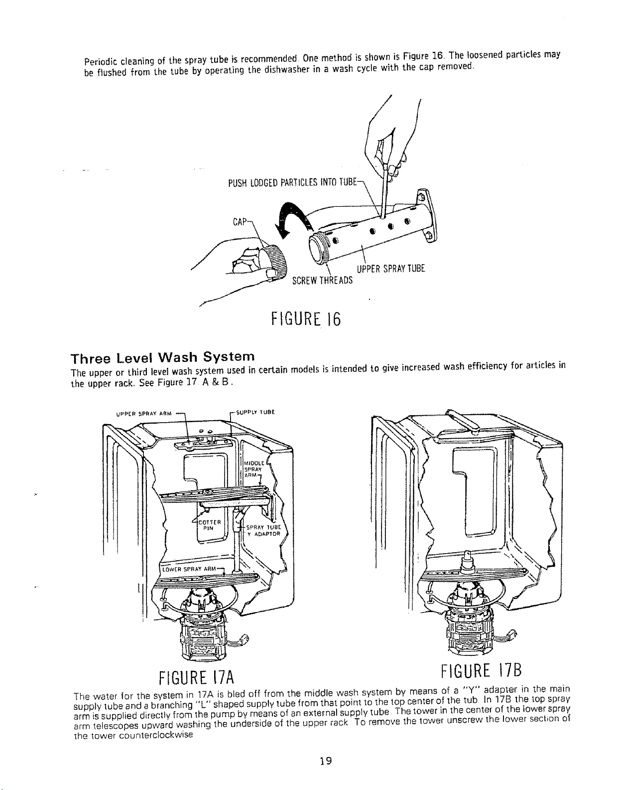
Periodic cleaning of the spray tube is recommended Onemethodis shown is Figure 16. The loosened particles may
be flushed from the tube by operating the dishwasher in a wash cycle with the cap removed,
PUSHLODGEDPARTICLES
UPPERSPRAYTUBE
SCREWTHREADS
FIGURE16
Three Level Wash System
The upper or third level wash system used in certain models is intended to give increased wash efficiency for articles in
the upper rack° See Figure ]7 A & B.
SPRAY 'iUBE
Y ADAPIDR
FIGURE17A FIGURE17B
The water for the system in 17A isbled off from the middle wash system by means of a "Y" adapter in the main
supply tube and a branching "L" shaped supplytube from thatpointtothe lop centerof the tub In 17B the top spray
arm is supptied directly from 1he pump by means of an external supply tube The tower in the center of the lower spray
arm telescopes upward washing the underside of the upper rack To remove the tower unscrew the lower section of
the tower counterclockwise
19
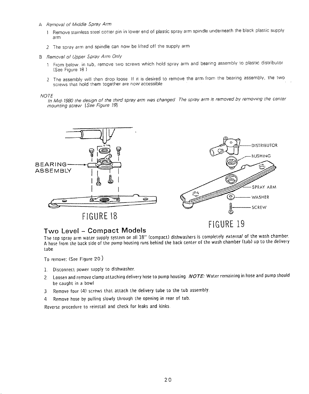
A Removal of Mtddle Spray Arm
1 Remove stainless steeI cotter pin in lower end of plastic spray arm spindle underneath the black plastic supply
arm
2 The spray arm and spindle can now be lifted off the supply arm
Removal of Upper Spray Arm Only
1 From below, in tub, remove two screws which hold spray arm and bearing assembly to plastic distributor
(See Figure 18 )
2 The assembly will then drop loose If il is desired to remove the arm from the bearing assembly, the 1we
screws the1 hold them together are nowraccessibte
NOTE
In Mid- 1980 [he design of the third ,spray arm was changed The spray arm is removed by removing the center
moun_ing screw [See Figure 79]
BEARING
ASSEMBLY
&$
ARM
;HER
(_ SCREW
FIGURE18
FIGURE19
Two Level - Compact Models
The top spray arm water supply system on all 18" (compact) dishwashers is completely external of the wash chamber,
A hose from the back side of the pump housing runs behind the back center of the wash chamber (tub) up to the delivery
tube
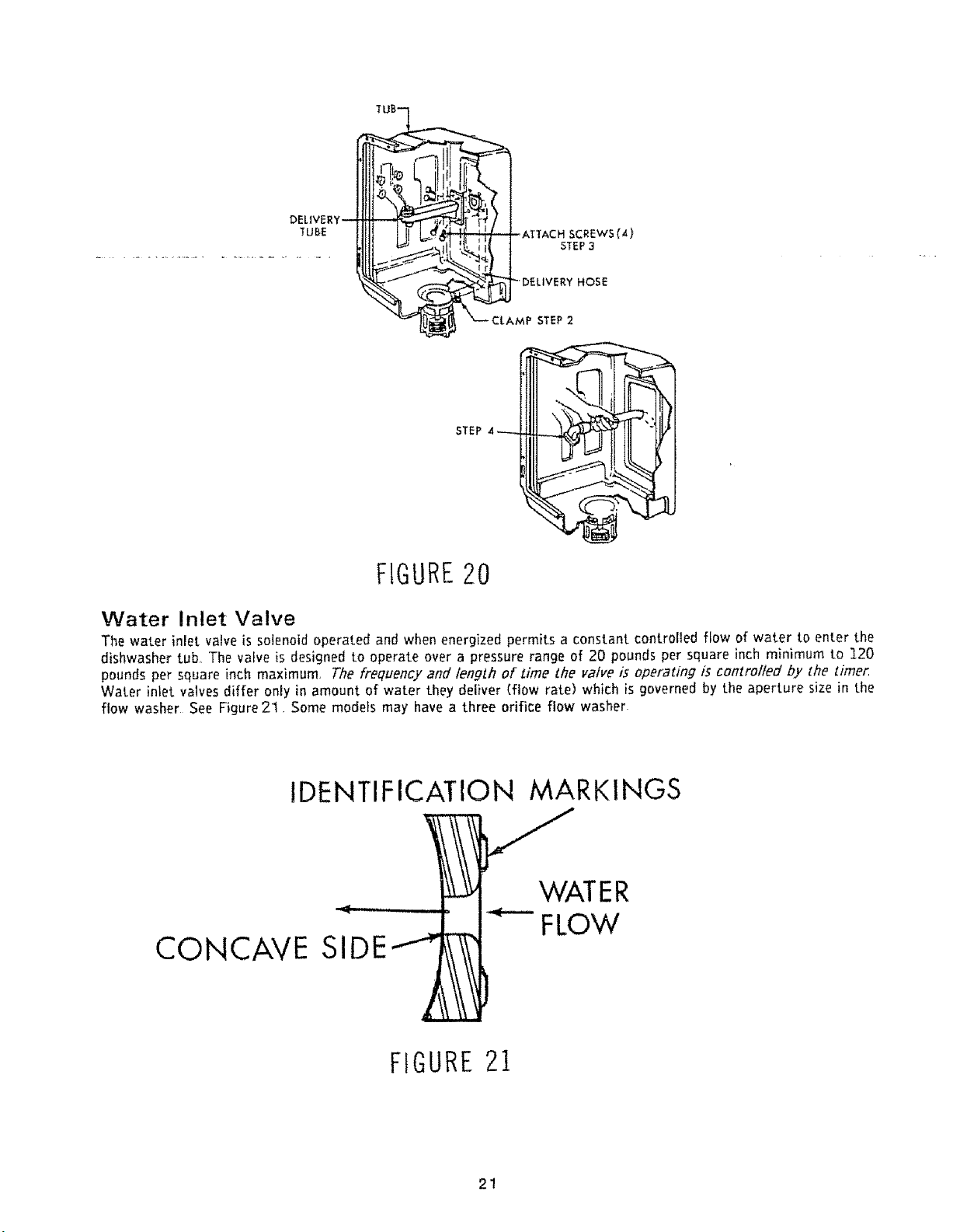
To remove: (See Figure 20)
1, Disconnect power supply to dishwasher,
2 Loosenandremoveclamp attaching deliveryhoseto pump housing /VOTE: Water remaining in hoseand pump should
be caught in a bowl
3 Remove four (4) screws that attach the delivery tube to the tub assembly,
4 Remove hose by pulling slowly through the opening in rear of tub.,
Reverseprocedure to reinstalf and check for leaks and kinks,
20
DELIVER
TUBE
HOSE
STEP 2
STEP
FIGURE20
Water Inlet Valve
The water inlet valve is solenoid operated and when energized permits a constant controlled flow of water to enter the
dishwasher tub, The valve is designed to operate over a pressure range of 20 pounds per square inch minimum to 120
pounds per square inch maximum, The frequency and length of Lime the valve is operating is controlled by the timer,
Water inlet valves differ only in amount of water they deliver (flow rate) which is governed by the aperture size in the
flow washer See Figure 21, Some models may have a three orifice flow washer
CONCAVE
IDENTIFICATION MARKINGS
"_WATER
' __1 '_-" FLOW
SIDE
FIGURE21
21
A
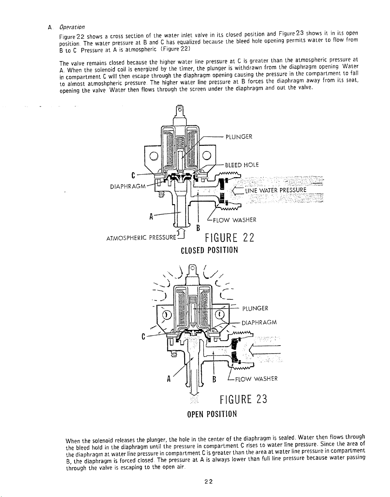
Operation
Figure 22 shows a cross section of the water inlet valve in its closed position and Figure 23 shows it in its open
position The water pressure at B and C has equalized because the bleed hole opening permits water to flow from
B to C Pressure at A is atmospheric (Figure 2.2)
The valve remains closed because the higher water line pressure at C is greater than the atmospheric pressure at
A. When the solenoid coil is energized by the timer, the plunger is withdrawn from the diaphragm opening Water
in compartment C wilt then escape through the diaphragm opening causing the pressure in the compartment to fall
to almost atmoshpheric pressure, The higher water line pressure at B forces the diaphragm away from its seat,
opening the valve Water then flows through the screen under the diaphragm and out the valve.
PLUNGER
HOLE
LINE WATER PRESSURE
ATMOSPHERIC PRESSURE£ B
CLOSEDPOSITION
WASHER
FIGURE22
PLUNGER
DIAPHRAGM
B -FLOW WASHER
FIGURE23
OPEN POSI'[ION
When the solenoid releasesthe plunger, the hole in the center of the diaphragm is sealed. Water then flows through
the bleed hold in the diaphragm until the pressure in compartment C rises to water line pressure. Since the area of
the diaphragm at water line pressurein compartment Cis greater than the area at water finepressure in compartment
B, the diaphragm is forced closed. The pressure at A is always lower than full line pressure because water passing
through the valve is escaping to the open air.
22
Testing
To test operation of water inlet valve, place the leads of a volt meter across the termina{s of the solenoid in any
fill phase of the operating cycle where the water inlet valve should be energized If the meter indicates tine
voltage, water should flow into the tub If water does not flow into the tub, either the water inlet valve is defective
or the water supply is inadequate Make certain the hot water faucet is fully on If the water supply is not at fault,
the water inlet valve is defective
C
Sen/zcing
To Clean Operating Parts of the Vaive:
! Remove valve bracket from tub or installation module
2 Remove 4 screws holding solenoid, valve body and bracket together
3 Remove the plunger housing, spring and plunger
4 Check the parts for defects, dirt particles or for formation of lime
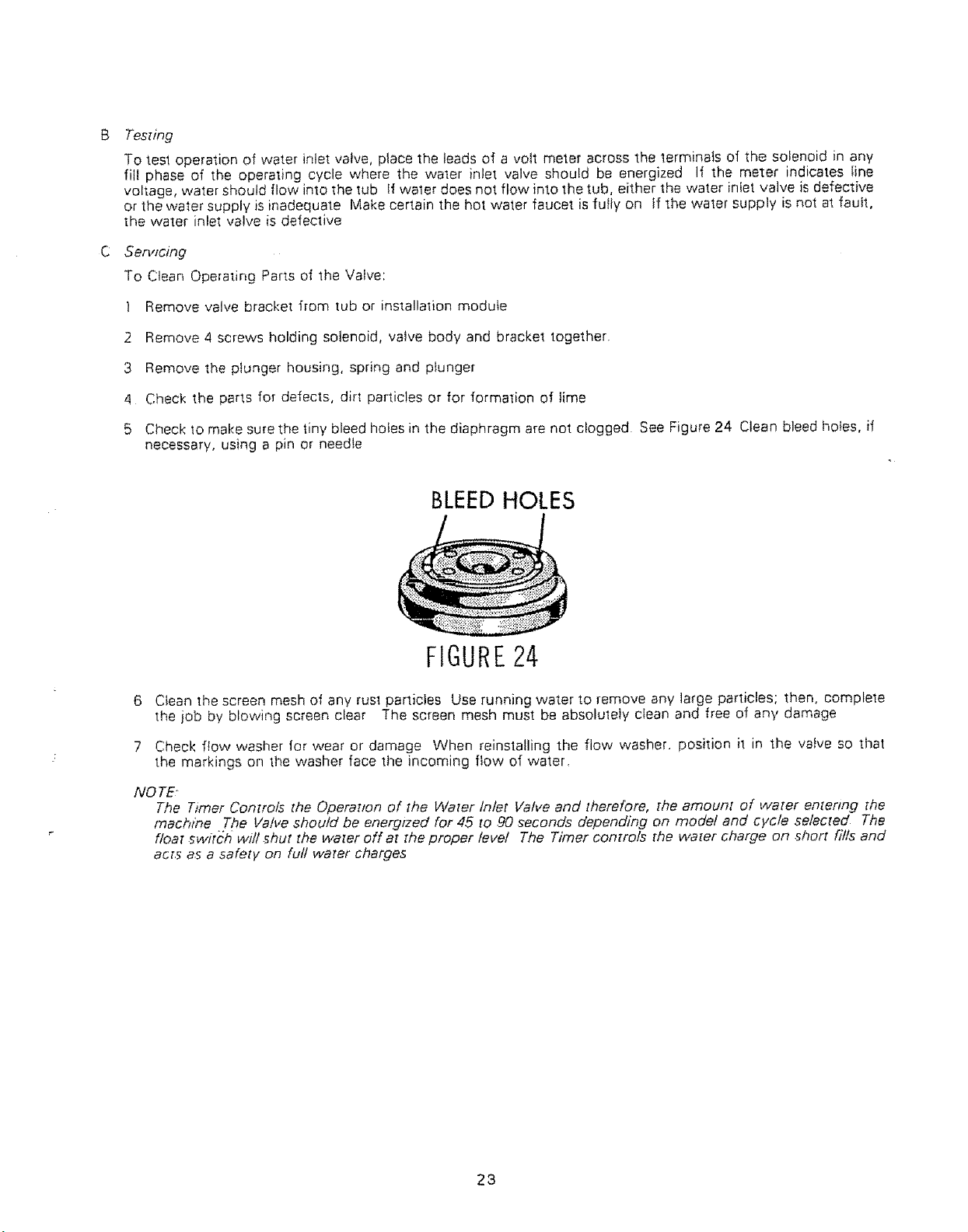
5 Check 1o make sure the tiny bleed hoies in the diaphragm are not clogged See Figure 24 Clean bleed holes, if
necessary, using a pin or needte
BLEED HOLES
FIGURE24
6
Clean the screen mesh of any rust particles Use running water to remove any large particles; then, complete
the iob by blowing screen clear The screen mesh must be absolutely clean and free of any damage
7
Check flow washer for wear or damage When reinstalling the flow washer, position i1 in the valve so that
the markings on the washer face the incoming flow of "water.
NOTE
The Timer Controls the Operazton of the Water Inlet Valve and therefore, the amount of water emenng the
machine The Valve should be energzzed for 45 to .90 ._econds depending on model and cycle selected The
float switch will .shut the water off at the proper level The Timer controls the wa[er charge on short fills and
acts as a safety on full water charges
23
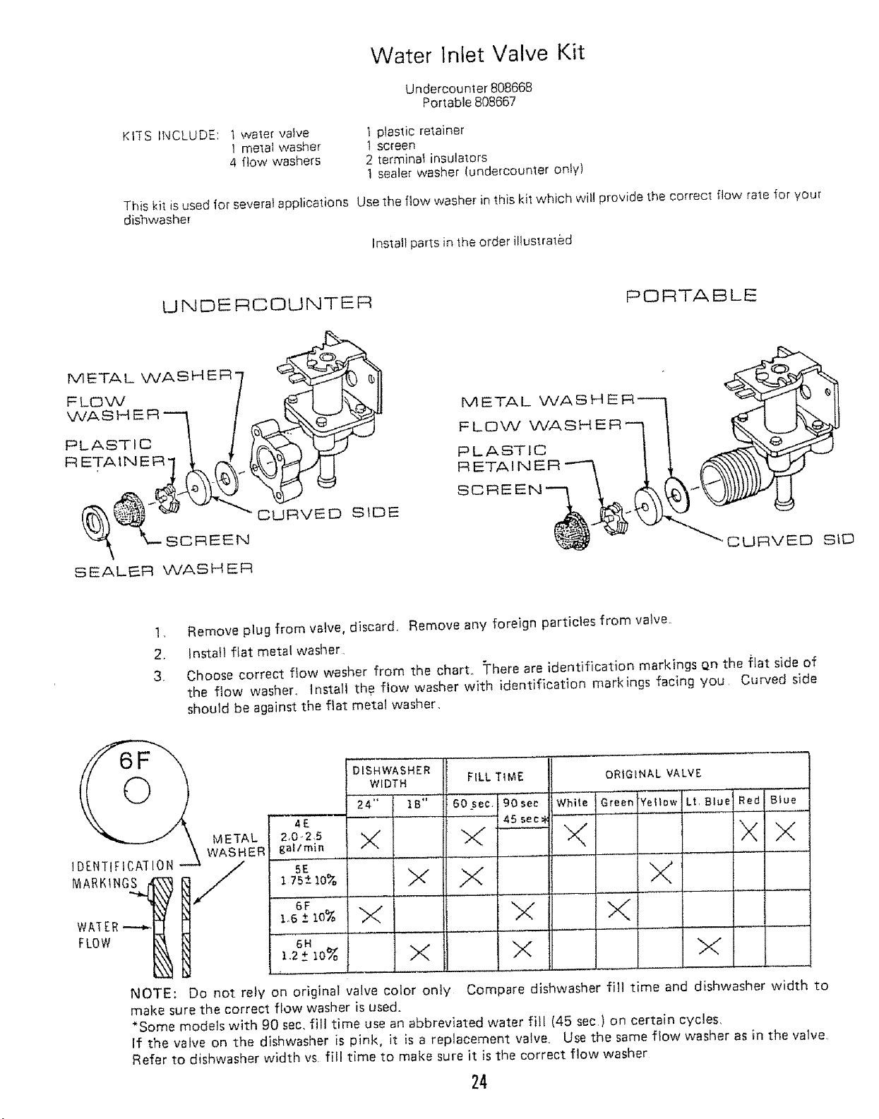
Water Inlet Valve Kit
Undercounler 808668
Portable 808667
KI'[S INCLUDE: t water vane
This ki_is used for several applications Use the flew washer in this kit which wi_! provide the correct flow rate for your
dishwasher
UNDERCOUNTER
METAL WASHER"
FLOW
WASHER--'_
PLASTIC _ ]
F:RETAIN E __
(__ SCREEN
! metal washer
4 flow washers
CURVED SIDE
t plastic retainer
1 screen
2 terminal insulators
t sealer washer (undercounter only)
Install parts in the order illustrated
PORTABLE
METAL
FLOW WASHE
PLASTIC
RETAINER
SCREEN
SEALER WASHER
1 Remove plug from valve, discard Remove any foreign particles from valve
2. install flat metal washer,
3, Choose correct flow washer from the chart. =Fhereare identification markings Qn the fiat side of
the flow washer° Install the flow washer with identification markings facing you Curved side
should be against the ftat metal washer.
IDENTIFICATION
MARKING_
METAL
WASHER
4E
2,0,2,5
_af/min
5E
175_-lo%
6F
1,6 Z 10%
DISHWASHER
WIDTH
24'; IB" '"
X
X
X
X
FILL TIME
-60sec,(gO see
---'-----1 45 sec_
F---
X
b<
X
ORIGINAL VALVE
Whiiei_'oeo
E ....
"Yellow Lt, Blue Red
IX
X
b<
Biue
X
NOTE:
make sure the correct flow washer is used.
*Some models with 90 sec. fill time use an abbreviated water fill (45 sec) on certain cycles.
If the valve on the dishwasher is pink, it is a replacement valve, Use the same flow washer as in the valve
Refer to dishwasher width vs, fill time to make sure it is the correct flow washer
Do not rely on original valve color only Compare dishwasher fill time and dishwasher width to
24
4, Install plastic retainer into valve with center protrusion facing you, Push untii it snaps into the groove
cut into the body of the valve
Press screen into valve, being careful not to crush or change the shape of the screen,, This is important
to keep dirt particles out of the valve tha't will cause it to malfunction,
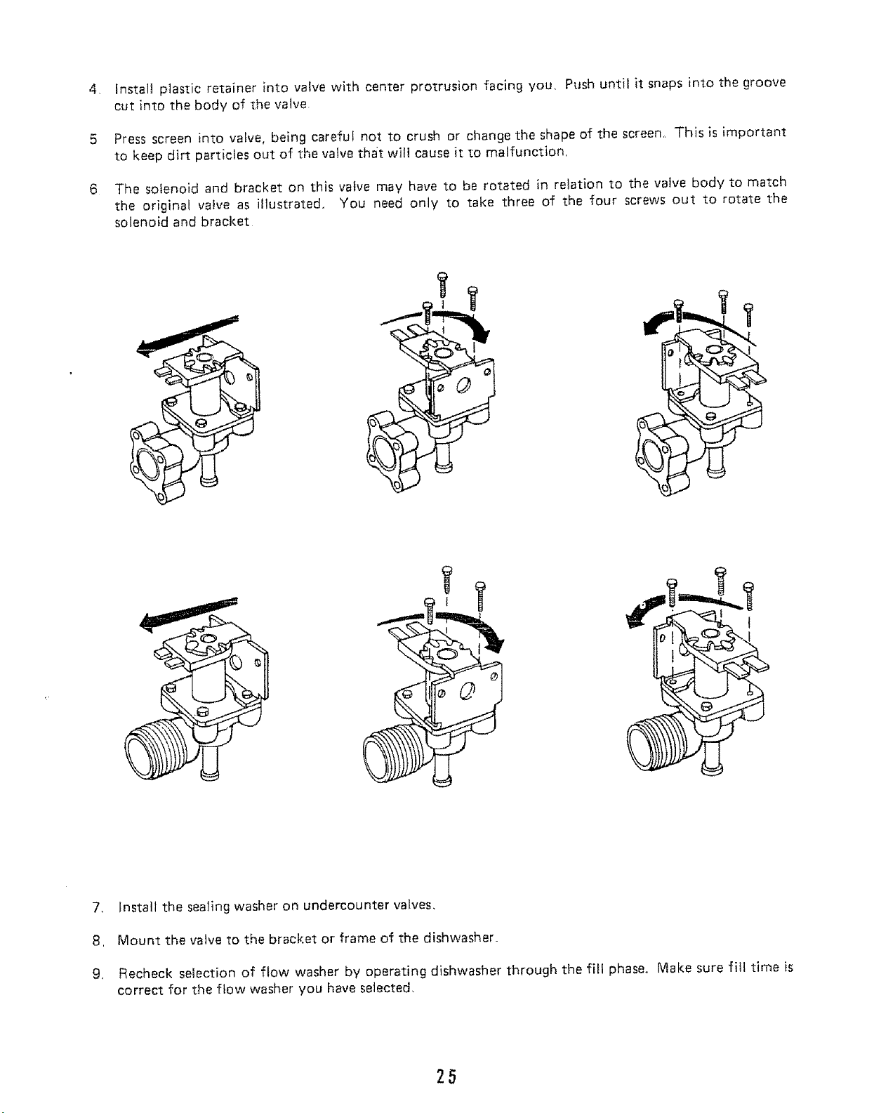
6
The solenoid and bracket on this valve may have to be rotated in relation to the vatve body to match
the original valve as illustrated, You need only to take three of the four screws out to rotate the
solenoid and bracket
7., Install the sealing washer on undercounter valves,
8, Mount the valve to the bracket or frame of the dishwasher_
9. Recheck selection of flow washer by operating dishwasher through the fill phase° Make sure fill time is
correct for the flow washer you have selected,
25
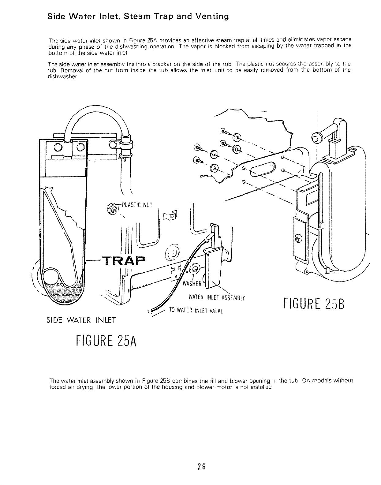
Side Water Inlet, Steam Trap and Venting
The side water inlet shown in Figure 25A provides an effective steam trap at all times and eliminates vapor escape
during any phase of the dishwashing operation The vapor is blocked from escaping by the water trapped in the
bottom of the side water inlet
The side water inlet assembly fits into a bracket on the side of the tub The plastic nut secures the assembly to the
tub Removal of the nul from inside the tub allows the inlet unit to be easily removed from the botlom of the
dishwasher
PLASTICNUT I
-,..
WA1ERiNLETASSEMBLY
FIGURE25B
TOWATERINLETVALVE
SIDE WATER INLET
FIGURE25A
The water inlet assembly shown in Figure 25B combines the fill and blower opening in the lub On models without
forced air drying, the lower portion of the housing and blower motor is not installed
26
 Loading...