

Kenmore 5871540590 Installation Guide
Printed in U. S. Ao 154043601A
Before You Begin
Please read this book completely before you begin. The instructions will help you anticipate drain, water and
electrical connections and help you select the best location for your dishwasher.
BE SURE YOU OBSERVE ALL LOCAL CODES AND ORDINANCES FOR ELECTRICAL AND PLUMBING
CONNECTIONS. ALL ELECTRICAL AND PLUMBING WORK SHOULD BE DONE BY QUALIFIED PERSON-
NEL.
Plan The Ins_allation
Locate the dishwasher where there is easy access to existing drain, water and electrical lines, Be sure the water
inlet valve is protected from freezing. If the valve freezes, flooding may occur.
The best location for the dishwasher is on either side of the kitchen sink. This provides access to plumbing and is
convenient for loading.
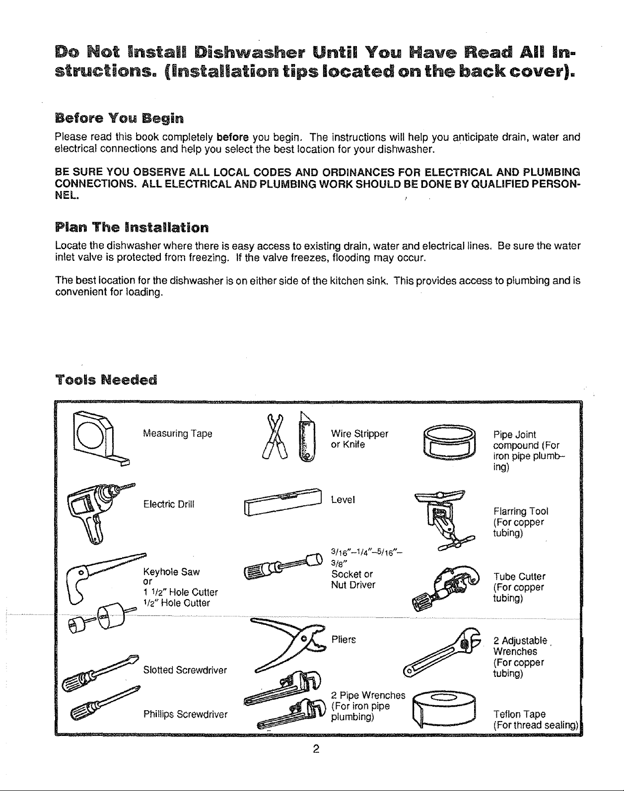
Tools Needed
i ...............
Wire Stripper Pipe Joint
Measuring Tape
or Knife compound (For
iron pipe plumb-
ing)
Electric Drill
Level
(For copper
Flarring Tool
tubing)
r _ 3/t6"--I/4'*-'5/16"-
\ \ 1 /2 Hole Cutter .._ .. Li__,
,!!ilHo!eGu!!e r ........... _ ,uuugj .
//""_'_ _.,....-.,_U Wrenches
_Siotted Screwdriver _ 2 Pipe Wrenches_ IFl_[nCc_pperg
_ Phi,lips Screwdriver _ (iFu°rbir°g_ipe _ _Feof,rOt_TeaaPdeseaiing)
90°
H
Line
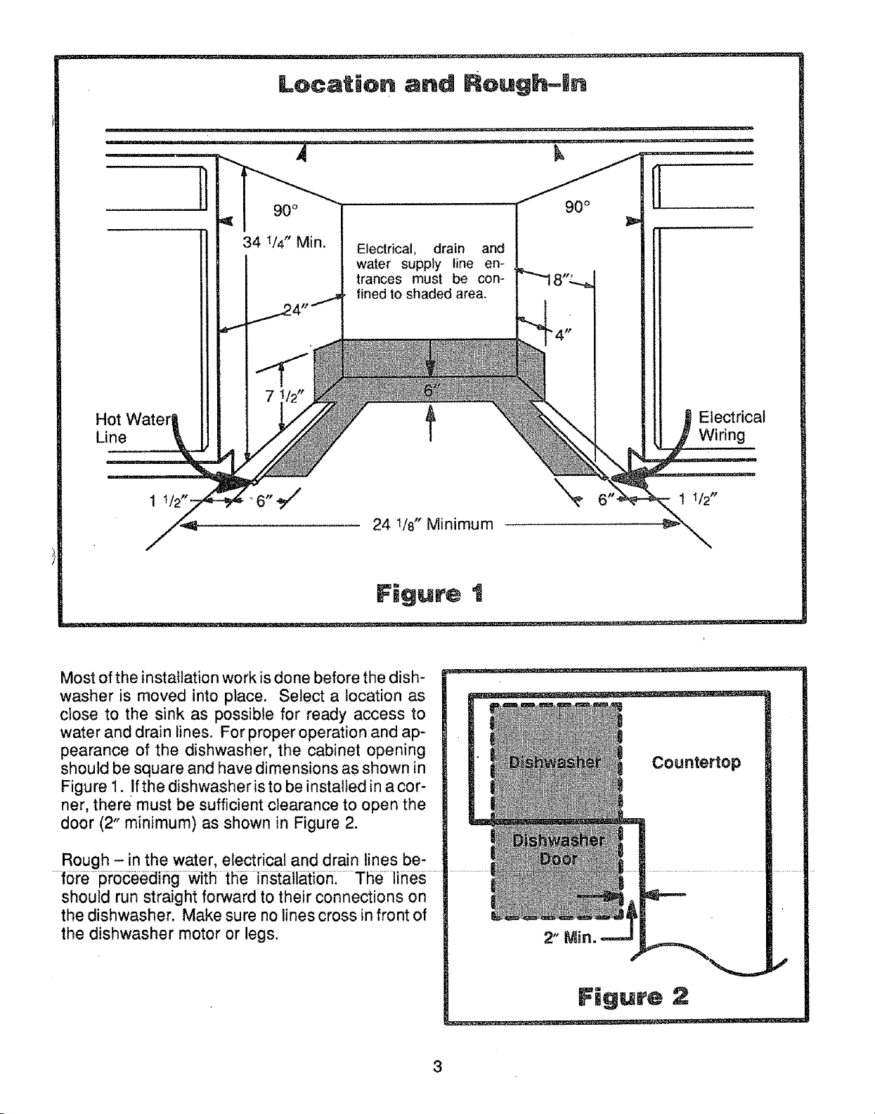
34 V4" Min.
Electrical, drain and
water supply line en-
trances must be con-
fined to shaded area.
f
Electrical
Wiring
Most of the installation work is done before the dish-
washer is moved into place. Select a location as
close to the sink as possible for ready access to
water and drain lines. For proper operation and ap-
pearance of the dishwasher, the cabinet opening
should be square and have dimensions as shown in
Figure 1. Ifthe dishwasheris to be installed in acor-
ner, there must be sufficient clearance to open the
door (2" minimum) as shown in Figure 2.
Rough - in the water, electrical and drain lines be-
f6repi;ocee_ing with tlie installatio
should run straight forward to their connections on
the dishwasher. Make sure no lines cross in front of
the dishwasher motor or legs.
3
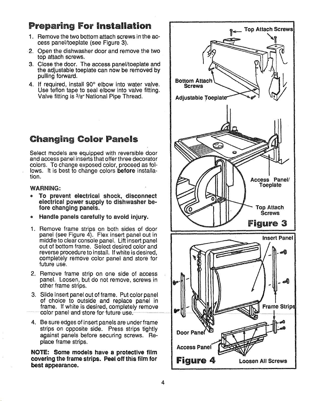
Preparing For |nstallation
1. Remove the two bottom attach screws inthe ac-
cess panel!toeplate (see Figure 3).
2. Open the dishwasher door and remove the two
top attach screws.
3. Close the door. The access panel/toeplate and
the adjustable toeptate can now be removed by
pulling forward.
4. If required, install 90° elbow into water valve.
Use teflon tape to seal elbow into valve fitting.
Valve fitting is 3/8_National Pipe Thread.
Changing Color Panels
Select models are equipped with reversible door
and access panel inserts that offer three decorator
colors. To change exposed color, proceed as foF
lows. It is best to change colors before installa-
tion.
WARNING:
• To prevent electrical shock, disconnect
electrical power supply to dishwasher be-
fore changing panels.
. Handle panels carefully to avoid injury.
Bottom
Screws
Adjustable Toepl=
Access Panel!
Toeplate
Top Attach
Screws
1. Remove frame strips on both sides of door
panel (see Figure 4). Flex insert panel out in
middle to clear console panel. Lift insert panel
out of bottom frame. Select desired color and
reverse procedure to install. Ifwhite is desired,
completely remove color panel and store for
future use.
2. Remove frame strip on one side of access
panel. Loosen, but do not remove, screws in
other frame strips.
3. Slide insert panel out of frame. Put color panel
of choice to outside and replace panel in
frame, tf white is desired, completely remove
color panel and store for future use.
.
Be sure edges of insert panels are under frame
strips on opposite side. Press strips tightly
against panels before securing screws. Re-
place frame strips.
NOTE: Some models have a protective film
covering the frame strips. Peel off this film for
best appearance.
Door
Access Panel
Figure 4
ii i, i, ,,,i
Loosen All Screws
ilLUI ' I'I_1'111
4
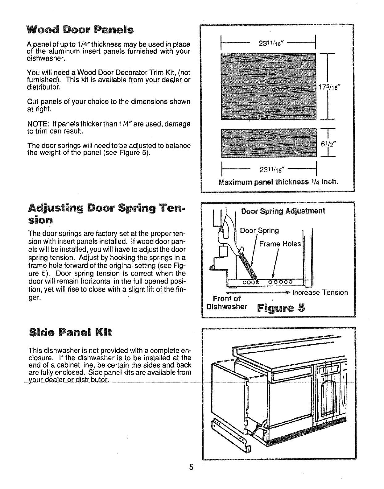
Wood Door Panels
A panel of upto 1/4"thickness may be used in place
of the aluminum insert panels furnished with your
dishwasher.
You will need a Wood Door Decorator Trim Kit, (not
furnished). This kit is available from your dealer or
distributor.
Cut panels of your choice to the dimensions shown
at right.
NOTE: If panels thicker than 1/4" are used, damage
to trim can result.
The door springs will need tobe adjusted to balance
the weight of the panel (see Figure 5).
-r-
6112pp
_J_
I
I 2311/16"
Maximum panel thickness 1/4 inch.
Adjusting Door Spring Ten-
sion
The door springs are factory set at the proper ten-
sion with insert panels installed. If wood door pan-
els will be installed, you will have to adjust the door
spring tension. Adjust by hooking the springs in a
frame hole forward of the original setting (see Fig-
ure 5). Door spring tension is correct when the
door will remain horizontal in the full opened posi-
tion, yet will rise to close with a slight lift of the fin-
ger.
Side Pane[ Kit
This dishwasher is not provided with a complete en-
closure. If the dishwasher is to be installed at the
end of a cabinet line, be certain the sides and back
are full 'enclosed. Side panel kits are available from
Door Spring Adjustment
Door Spring
 Loading...