

Service Manual
®
ROOMAIRCONDITIONER
Model: 79053/79056/79074/79122
79184/79188
• PREFACE
• DISASSEMBLY INSTRUCTIONS
• INSTALLATION
• TROUBLESHOOTING GUIDE
• CIRCUIT DIAGRAM
• EXPLODED VIEW AND SERVICE PARTS LIST
CAUTION
- BEFORE SERVICING THE UNIT, READ THE
"SAFETY PRECAUTIONS" IN THIS MANUAL.
- ONLY FOR AUTHORIZED SERVICE
PERSONNEL.
Sears, Roebuck and Co., Hoffman Estates, IL. 60179 U.S.A.
CONTENTS
1. PREFACE ..................................................................................................................................................3
1.1 FEATURES .................................................................................................................................................. 3
1.2 SPECIFICATIONS ........................................................................................................................................ 3
1.3 LOCATIONS OF CONTROLS ...................................................................................................................... 4
1.4 SAFETY PRECAUTIONS ............................................................................................................................ 8
1.5 INSULATION RESISTANCE TEST ..................................................................... "......................................... 8
2. DISASSEMBLY INSTRUCTIONS ..............................................................................................9
• MODELS: 79053/79056 .................................................................................................................................. 9
• MODEL: 79074 .............................................................................................................................................. 15
• MODEL: 79122 .............................................................................................................................................. 20
• MODELS: 79184/79188 ................................................................................................................................ 25
3. INSTALLATION ...................................................................................................................................32
• MODELS: 79053/79056 ................................................................................................................................ 32
• MODELS: 79074/79122 ................................................................................................................................ 34
• MODELS: 79184/79188 ................................................................................................................................ 37
4. TROUBLESHOOTING GUIDE ...................................................................................................40
4.1 OUTSIDE DIMENSIONS ............................................................................................................................ 40
4.2 PIPING SYSTEM ....................................................................................................................................... 41
4.3 TROUBLESHOOTING GUIDE ................................................................................................................... 42
5. CIRCUIT DIAGRAM ..........................................................................................................................47
• MODEL: 79053 .............................................................................................................................................. 47
• MODEL: 79056 .............................................................................................................................................. 48
• MODEL: 79074 .............................................................................................................................................. 49
• MODEL: 79122 .............................................................................................................................................. 50
• MODEL: 79184 .............................................................................................................................................. 51
• MODEL: 79188 .............................................................................................................................................. 52
6. EXPLODED VIEW AND SERVICE PARTS LIST ...........................................................53
• MODEL: 79053 .............................................................................................................................................. 53
• MODEL: 79056 .............................................................................................................................................. 56
• MODEL: 79074 .............. "............................................................................................................................... 59
• MODEL: 79122 .............................................................................................................................................. 62
• MODEL: 79184 .............................................................................................................................................. 65
• MODEL: 79188 .............................................................................................................................................. 68
--2--
1. PREFACE
This service manual provides various service information, including the mechanical and electrical parts, etc.
This room air conditioner was manufactured and assembled under a strict quality control system.
The refrigerant is charged at the factory. Be sure to read the safety precautions prior to servicing the unit.
1.1 FEATURES
• DESIGNED FOR COOLING ONLY
• POWERFUL AND INCREDIBLE COOLING
• THE SIMPLE INSTALLATION AND SERVICE
• BUILT-IN ADJUSTABLE THERMOSTAT
• WASHABLE ONE-TOUCH FILTER
• COMPACT SIZE
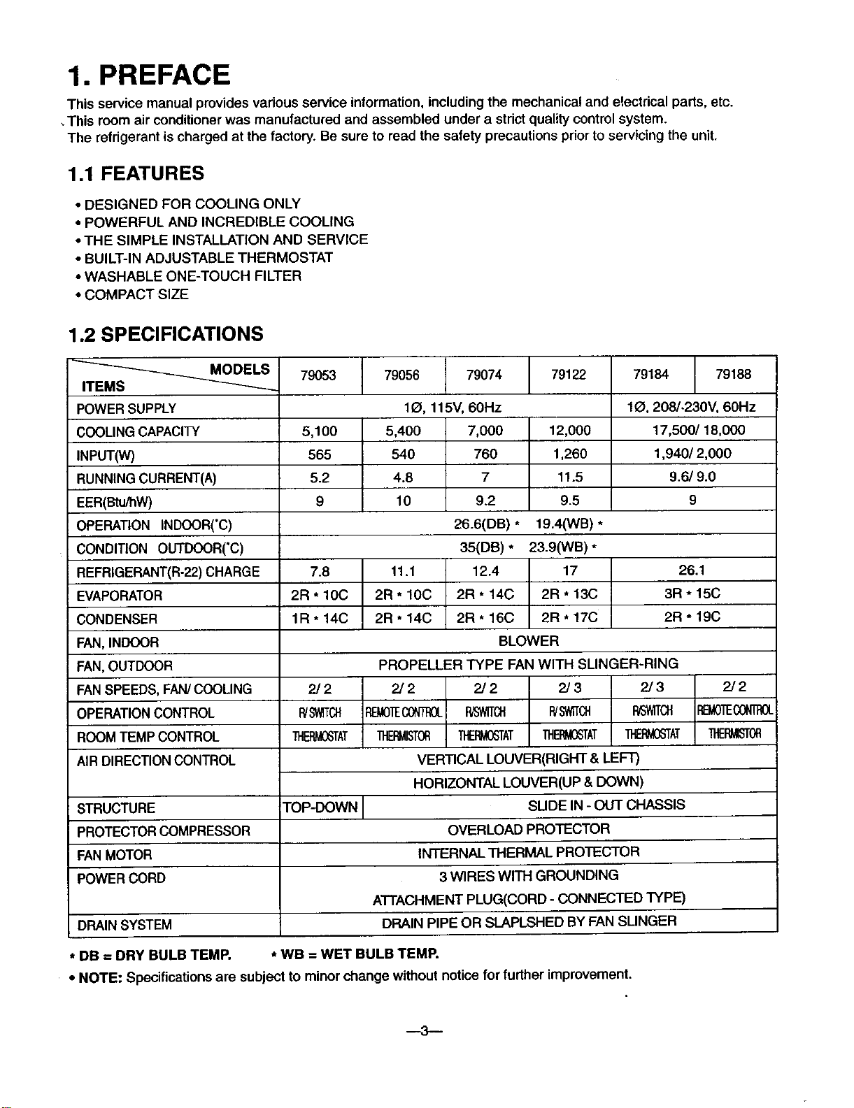
1.2 SPECIFICATIONS
__ MODELS
ITEMS
POWER SUPPLY
COOLING CAPACITY
INPUT(W)
RUNNING CURRENT(A)
EER(Btu/hW)
OPERATION INDOOR('C)
CONDITION OUTDOOR('C)
REFRIGERANT(R-22) CHARGE
EVAPORATOR
CONDENSER
FAN,INDOOR
FAN,OUTDOOR
FANSPEEDS, FAN/COOLING
OPERATIONCONTROL
ROOM TEMP CONTROL
AIR DIRECTION CONTROL
STRUCTURE TOP-DOWN
PROTECTOR COMPRESSOR
FAN MOTOR
POWER CORD
DRAIN SYSTEM
79053 79056 79074 79122
5,100
565
5.2
9
7.8
2R * 10C
1R * 14C
2/2
R/St_T_
THERMOSTAT
79184 79188
1(_, 115V,
5,400
540
4.8
10
11.1
2R * 10C
2R * 14C
PROPELLER TYPE FAN WITH SLINGER-RING
2/2 2/2 2/3 2/3
P,B/_)]Ecokr'_OL RISWlTCH R/SWITCH R_'WlTCH
11"IE_ISTOB _IEEV_3_rAT THE!_'TAT _AT
VERTICAL LOUVER(RIGHT & LEFT)
HORIZONTAL LOUVER(UP & DOWN)
INTERNAL THERMAL PROTECTOR
ATTACHMENT PLUG(CORD - CONNECTED TYPE)
DRAIN PIPE OR SLAPLSHED BY FAN SLINGER
60Hz
7,000
760
7
9.2
26.6(DB) *
35(DR) *
12.4
2R * 14C
2R * 16C
BLOWER
OVERLOAD PROTECTOR
3 WIRES WITH GROUNDING
12,000
1,260
11.5
9.5
19.4(WB) *
23.9(WB) *
17
2R * 13C
2R * 17C
SUDE IN - OUT CHASSIS
10, 208/-230V, 60Hz
17,500/18,000
1,940/ 2,000
9.6/9.0
26.1
3R "15C
2R "19C
2/2
REMOTECON]t_OL
]HER_ISTOR
* DB = DRY BULB TEMP. * WB = WET BULB TEMP.
• NOTE: Specifications are subject to minor change without notice for further improvement.
--3--
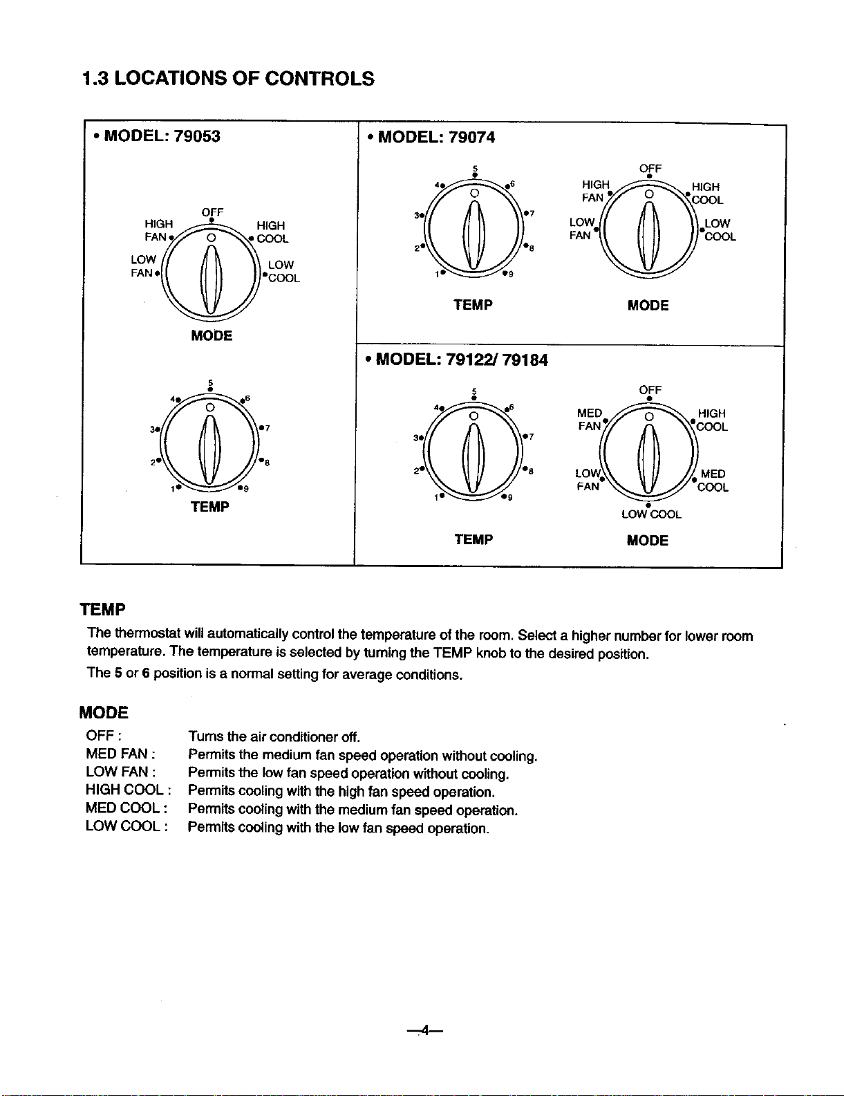
1.3 LOCATIONS OF CONTROLS
• MODEL: 79053
OFF
HIGH F-_--------_-._ HIGH
FANFF" -oooL
LOW /r I LOW
FAN'I _ ( !"cOOL
MODE
3• 4e •6 •7
TEMP
• MODEL: 79074
s OFF
FAN "gOOOL
HIGH_ HIGH
i ,. ow
2• _ % FAN 3 _i I r COOL
TEMP MODE
• MODEL: 79122/79184
5
3• •7 FAN e///f _ _'COOL
2 % LOW•_\ J_ / I MED
s OFF
MED _ HIGH
FAN _ COOL
LOW COOL
TEMP MODE
TEMP
The thermostat will automatically control the temperature of the room. Select a higher number for lower room
temperature. The temperature is selected by turningthe TEMP knob to the desired position.
The 5 or 6 position is a normal setting for average conditions.
MODE
OFF :
MED FAN :
LOW FAN :
HIGH COOL :
MED COOL :
LOW COOL :
Turns the air conditioner off.
Permits the medium fan speed operation without cooling.
Permits the low fan speed operation withoutcooling.
Permits cooling with the high fan speed operation.
Permits cooling with the medium fan speed operation.
Permits cooling with the low fan speed operation.
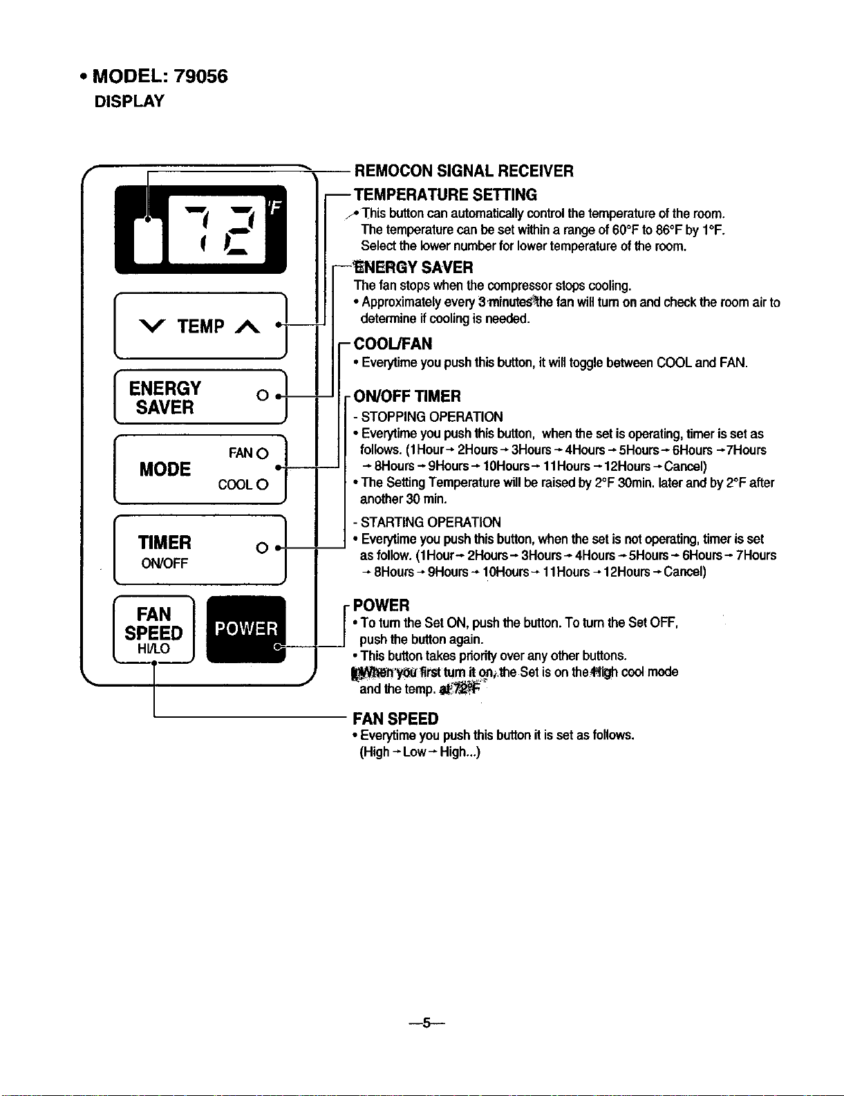
• MODEL: 79056
DISPLAY
REMOCON SIGNAL RECEIVER
-- TEMPERATURE SETTING
y' Th s buttoncan automaticay controthetemperatureoftheroom.
The temperaturecan be setwithina rangeof 60°F to86°F by I°F.
Selectthe lowernumberforlowertemperatureofthe room.
The fan stopswhenthe compressorstopscooling.
• Approximatelyevery3 minute_the fan willturnonand checkthe roomairto
determineifcoolingis needed.
--INERGY SAVER
OOUFAN
[ENERGY O _._._ I :I_:F_e_M;R shthisbutt°n'itwillt°gglebetweenCOOLandFAN"
_ SAVER _N OO_ I: STOPPING OPERATION
( T"T'_MER O ! ] ; STeArRtTImNGO:pEut_iONbutt°n,whentheset is n°t °perking ,umeris set
L ON/OFF_ [ as_lo°W__ HHUru"rs2H_JoHou3HlUlHo4H°urs"5H°urs 6H°urs 7H°urs
• To turn the Set ON, pushthe button.To rumthe Set OFF,
pushthe buttonagain.
-
• Thisbuttontakespriorityoveranyotherbuttons.
_jN_rl'y_ _irsttum it_the Set is onthe_gh coolmode
andthe temp._"
FAN SPEED
• Everytimeyoupushthis buttonitissetas follows.
(High--Low-- High...)
- 12Hours--_Cancel)
--5--
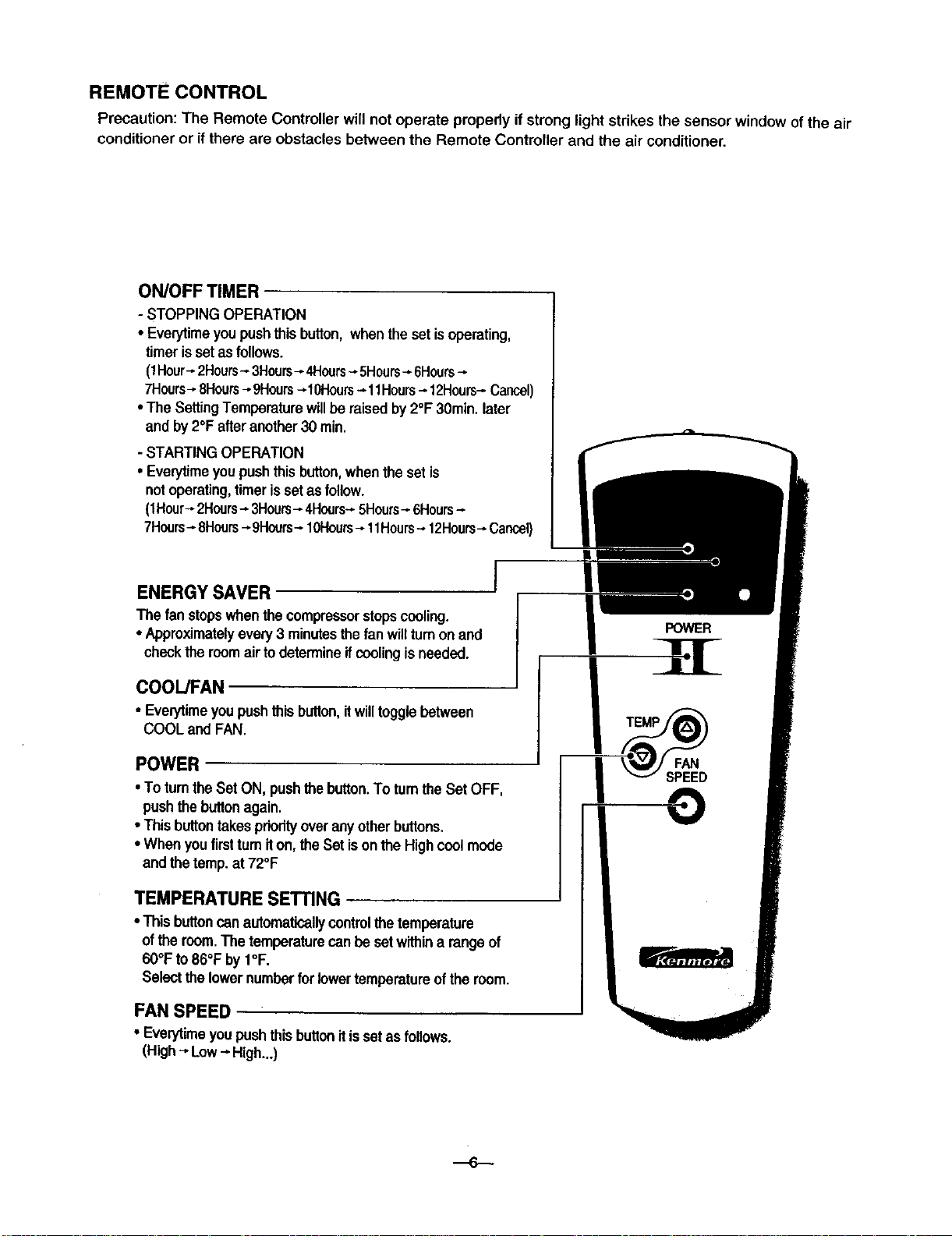
REMOTE CONTROL
Precaution: The Remote Controller will not operate propedy ifstrong light strikes the sensor window of the air
conditioner or if there are obstacles behveen the Remote Controller and the air conditioner.
ON/OFF TIMER
- STOPPING OPERATION
• Everytimeyou push this button, when the set isoperating,
timer is set as follows.
(1Hour=.2Hours- 3Hours- 4Hours- 5Hours-- 6Hours
7Hours-8Hours_-9Hours-10Hours_ 11Hours--12Hours_Cancel)
•The SettingTemperaturewillbe raisedby 2°F 30rain.later
and by2°F afteranother 30 rain.
- STARTING OPERATION
• Even/timeyou pushthis button,whenthe setis
not operating, timer is set as follow.
(1Hour_2Hours-*3Hours_ 4Hours-_5Hours_6Hours-
7Hours- 8Hours_-9Hours_ 10Hours_ 11Hours-_12Hours- Cancel)
ENERGY SAVER
The fan stopswhenthe compressorstopscooling.
• Approximatelyevely 3 minutesthe fan willtumon and
checkthe roomairto determineifcoolingisneeded.
COOL/FAN
• Eve_time youpushthis button,itwilltogglebetween
COOL and FAN.
POWER
• To turnthe Set ON, pushthe button.Totumthe Set OFF,
pushthe button again.
• Thisbuttontakespriorityoveranyotherbuttons,
• Whenyoufirstturniton, the Set ison the Highcoolmode
and thetemp. at72°F
TEMPERATURESETTING
• This buttoncanautomatically control thetemperature
of the room.The temperature can beset withina rangeof
60°Fto 86°F by I°F.
Selectthe lower number for lower temperature of the room.
FAN SPEED
• Everytimeyoupush thisbuttonitis set as follows.
(High--,Low-_High...)
POWER
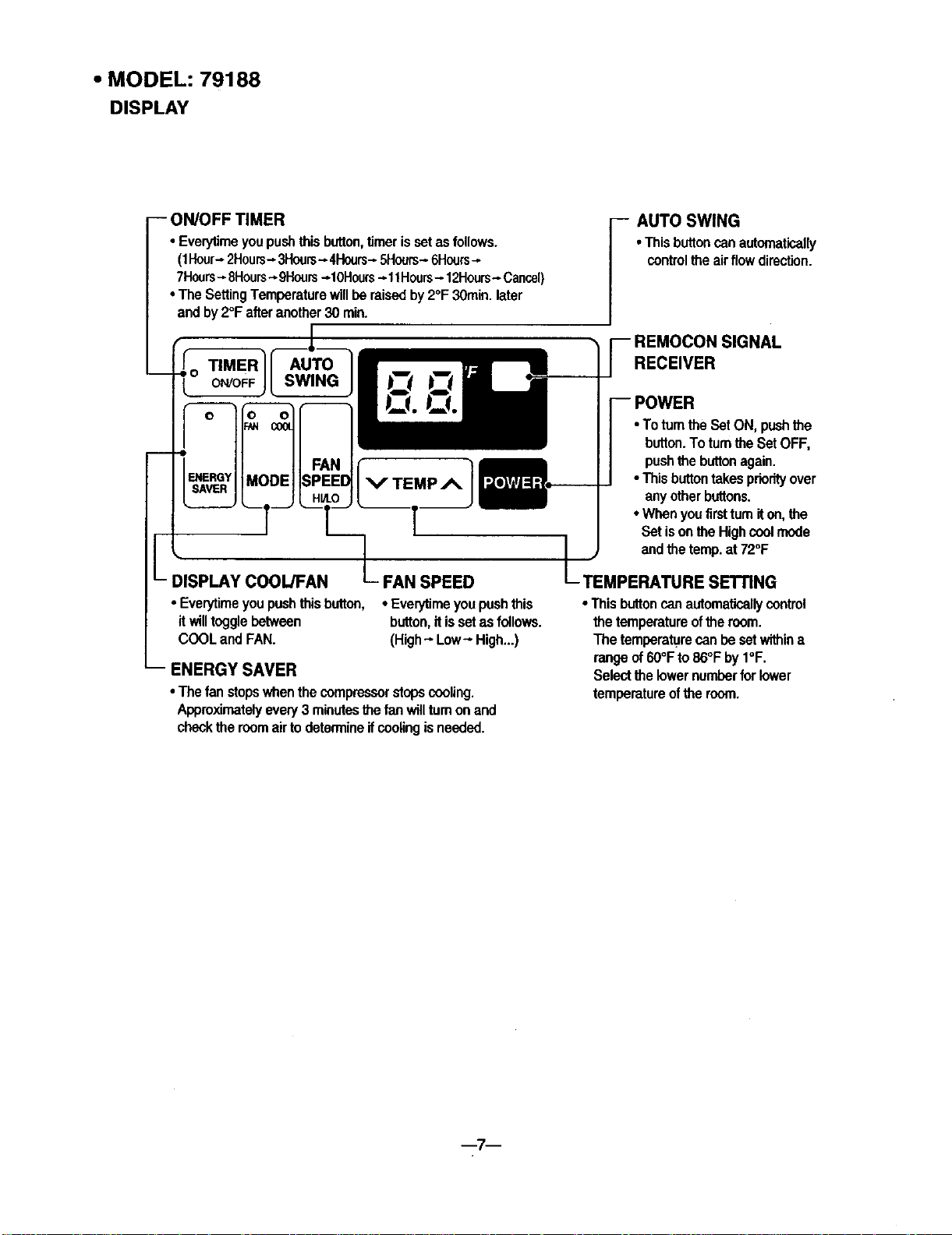
• MODEL: 79188
DISPLAY
-- ON/OFF TIMER
• Everyfimeyoupushthisbutton,timerissetasfollows,
(1Hour-2Hours- 3Hours-*4Hours_5Hours-6Hours-
7Hours_8Hours-*9Hours-*10Hours-*11Hours- 12Hours-Cancel)
• TheSettingTemperaturewillberaisedby2°F 30rain.later
andby2°F afteranother30 rain,
•This buttoncan automatically
controltheairflowdirection.
I UTO SWING
TIMER AUTO
L
,-0
FAN SPEED
• Everytimeyoupushthisbutton,
itwilltogglebetween
COOLandFAN.
ENERGY SAVER
•Thefanstopswhenthecompressorstopscooling.
Approximatelyevery3minutesthe fanwilltumonand
checkthe roomair todetermineif coolingis needed.
• EverylJmeyoupushthis
button,it issetasfollows,
(High_ Low- High...)
RECEIVER
•To turntheSetON, pushthe
button.TotumtheSetOFF,
pushthebuttonagain.
•This buttontakespriorityover
anyotherbuttons.
•Whenyoufirsttumiton, the
Setisonthe Highcoolmode
andthetemp.at72°F
TEMPERATURESETTING
• Thisbuttoncanautomatloailycontrol
thetemperatureoftheroom.
Thetemperaturecan be setwithine
rangeof60°Fto86°FbyI°F.
Selectthe lowernumberfor lower
temperatureoftheroom.
m7m
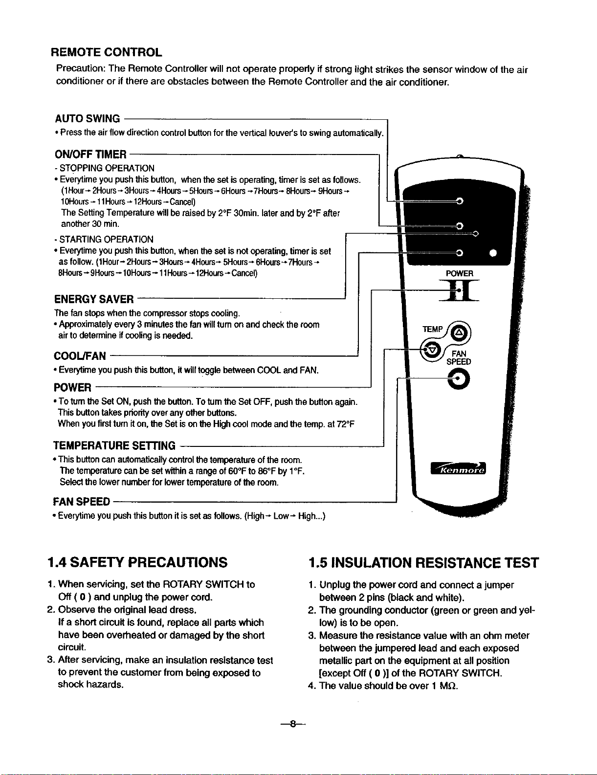
REMOTE CONTROL
Precaution: The Remote Controller will not operate properly if strong light strikes the sensor window of the air
conditioner or if there are obstacles between the Remote Controller and the air conditioner,
AUTO SWING
• Presstheairflowdirectioncontrolbuttonforthe verticalIouver'stoswingautomatically,
ON/OFF TIMER
- STOPPINGOPERATION
• Ever/timeyoupushthisbutton,whenthesetisoperating,timeris setasfollows.
(1Hour_2Hours_3Hours- 4Hours-5Hcers_ 6Hours--_7Hours-8Hours-9Hours-*
10Hours-11Hours-12Hours-Cancel)
TheSettingTemperaturewillberaisedby2°F 30rain.laterandby2°Fafter
another30 min.
- STARTINGOPERATION
• Everytimeyoupushthisbutton,whenthesetisnotoperating,timer isset
asfollow.(1Hour-2Hours- 3Hours-4Hours-5Hours-6Hours-_7Hours
8Hours-, 9Hours_ 10Hours_ 11Hours--12Hours--Cancel)
POWER
ENERGY SAVER
Thefanstopswhenthecompressorstopscooling,
•Approximatelyevery3minutesthe fanwillturnonandchecktheroom
airtodetermineifcoolingis needed.
COOL/FAN
• Everytimeyoupushthisbutton,itwilltogglebetweenCOOLandFAN.
FAN
SPEED
POWER
•To turntheSetON, pushthebutton.Totumthe SetOFF, pushthe buttonagain.
Thisbuttontakespriorityoveranyotherbuttons.
Whenyoufirstturniton,theSetis onthe Highcoolmodeandthe temp.at72°F
TEMPERATURE SEI"rlNG
• This buttoncanautomaticallycontrolthe temperatureofthe room.
The temperaturecanbe setwithina rangeof60°Fto86°F byI°F.
Selectthelowernumberforlowertemperatureofthe room.
FAN SPEED
• Everytimeyoupushthisbuttonit issetasfollows.(High---Low---High..,)
1.4 SAFETY PRECAUTIONS
1. When servicing, set the ROTARY SWITCH to
Off ( O ) and unplug the power cord.
2. Observe the original lead dress.
If a short circuit is found, replace all parts which
have been overheated or damaged by the short
circuit.
3. After servicing, make an insulation resistance test
to prevent the customer from being exposed to
shock hazards.
1.5 INSULATION RESISTANCE TEST
1. Unplug the power cord and connect a jumper
2. The grounding conductor (green or green and yel-
3. Measure the resistance value with an ohm meter
4. The value should be over 1 M_.
---8--
between 2 pins (black and white).
low) is to be open.
between the jumpered lead and each exposed
metallic part on the equipment at all position
[except Off ( 0 )] of the ROTARY SWITCH.
2. DISASSEMBLY INSTRUCTIONS
• MODEL: 79053/79056
2.1 MECHANICAL PARTS
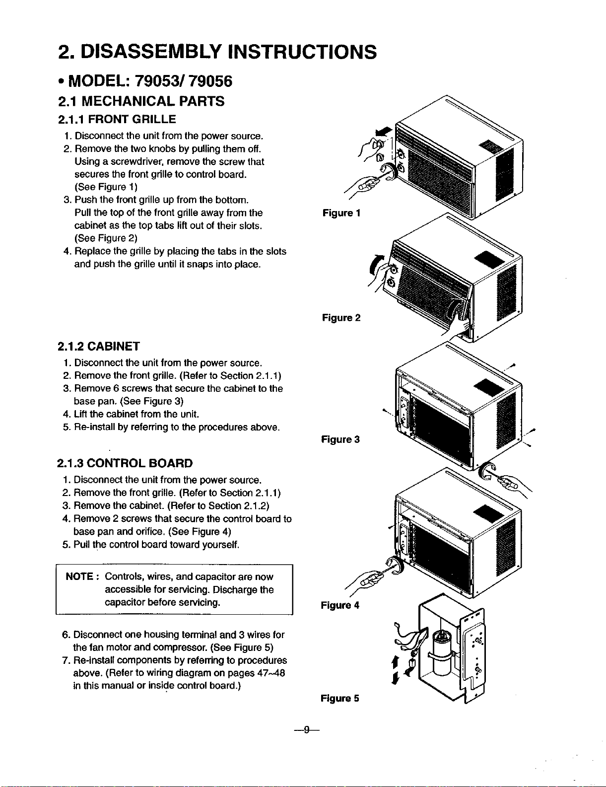
2.1.1 FRONT GRILLE
1. Disconnect the unit from the power source.
2. Remove the two knobs by pullingthem off.
Using a screwdriver, remove the screw that
secures the front grille to control board.
(See Figure 1)
3. Push the front grills up from the bottom.
Pull the top of the front grille away from the
cabinet as the top tabs lift out of their slots.
(See Figure 2)
4. Replace the grille by placing the tabs in the slots
and push the grille until itsnaps into place.
Figure 1
Figure 2
2.1.2 CABINET
1. Disconnect the unit from the power source.
2. Remove the front grille. (Refer to Section 2.1.1)
3. Remove 6 screws that secure the cabinet to the
base pan. (See Figure 3)
4. Lift the cabinet from the unit.
5. Re-install by referring to the procedures above.
2.1.3 CONTROL BOARD
1. Disconnect the unit from the power source.
2. Remove the front gdlle. (Refer to Section 2.1,1)
3, Remove the cabinet. (Refer to Section 2.1.2)
4. Remove 2 screws that secure the control board to
base pan and orifice, (See Figure 4)
5. Pull the control board toward yourself,
NOTE : Controls, wires, and capacitor are now
accessible for servicing. Discharge the
capacitor before servicing.
Figure 3
6. Disconnect one housing terminal and 3 wires for
the fan motor and compressor. (See Figure 5)
7. Re-install components by referring to procedures
above. (Refer to wiring diagram on pages 47-48
in this manual or inside control board.)
Figure 4 :_
Figure 5
--9---
2.2 AIR HANDLING PARTS
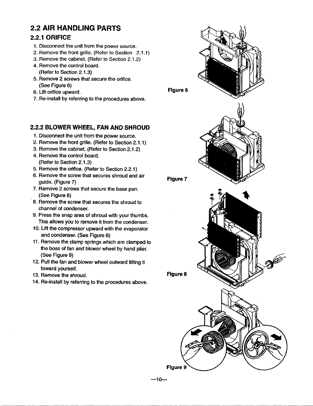
2.2.1 ORIFICE
1. Disconnect the unit from the power source.
2. Remove the front gdlle. (Refer to Section 2.1.1)
3. Remove the cabinet. (Refer to Section 2.1.2)
4. Remove the control board.
(Refer to Section 2.1.3)
5. Remove 2 screws that secure the orifice.
(See Figure 6)
6. Uft orifice upward.
7. Re-install by referring to the procedures above.
2.2.2 BLOWER WHEEL, FAN AND SHROUD
1. Disconnect the unit from the power source.
2. Remove the front gdlle. (Refer to Section 2.1.1)
3. Remove the cabinet. (Refer to Section 2.1.2)
4. Remove the control board.
(Refer to Section 2.1.3)
5. Remove the orifice. (Refer to Section 2.2.1)
6. Remove the screw that secures shroud and air
guide. (Figure 7)
7. Remove 2 screws that secure the base pan.
(See Figure 8)
8. Remove the screw that secures the shroud to
channel of condenser.
9. Press the snap area of shroud with your thumbs.
This allows you to remove it from the condenser.
10. Lift the compressor upward with the evaporator
and condenser. (See Figure 8)
11. Remove the clamp springs which are clamped to
the boss of fan and blower wheel by hand plier.
(See Figure 9)
12. Pull the fan and blower wheel outward tilting it
foward yourself.
13. Remove the shroud.
14, Re-install by referring to the procedures above.
Figure 6
Figure 7
Figure 8
--10--
Figure 9
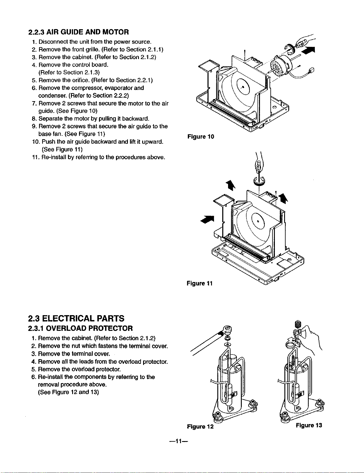
2.2.3 AIR GUIDE AND MOTOR
1. Disconnect the unit from the power source.
2. Remove the front grille. (Refer to Section 2.1.1)
3. Remove the cabinet. (Refer to Section 2.1.2)
4. Remove the control board.
(Refer to Section 2.1.3)
5. Remove the orifice. (Refer to Section 2.2.1 )
6. Remove the compressor, evaporator and
condenser. (Refer to Section 2.2.2)
7. Remove 2 screws that secure the motor to the air
guide. (See Figure 10)
8. Separate the motor by pulling it backward.
9. Remove 2 screws that secure the air guide to the
base fan. (See Figure 11)
10. Push the air guide backward and lift it upward.
(See Figure 11)
11. Re-install by referring to the procedures above.
Figure 10
2.3 ELECTRICAL PARTS
2.3.1 OVERLOAD PROTECTOR
1. Remove the cabinet. (Refer to Section 2.1,2)
2. Remove the nut which fastens the terminal cover.
3. Remove the terminal cover.
4. Remove all the leads from the overload protector.
5. Remove the ovedoad protector.
6. Re-install the components by referring to the
removal procedure above.
(See Figure 12 and 13)
Figure 11
Figure 12 Figure 13
--11--
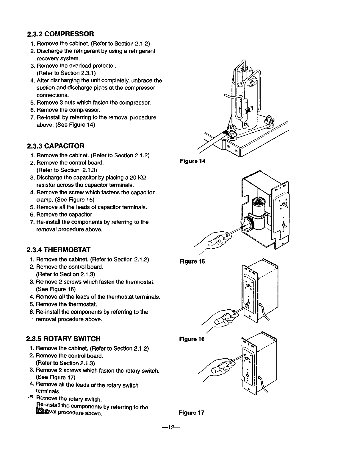
2.3.2 COMPRESSOR
1. Remove the cabinet. (Refer to Section 2.1.2)
2. Discharge the refrigerant by usinga refrigerant
recovery system,
3. Remove the overload protector.
(Refer to Section 2.3.1)
4. After discharging the unit completely, unbrace the
suction and discharge pipes at the compressor
connections.
5. Remove 3 nuts which fasten the compressor.
6. Remove the compressor.
7. Re-install by referring to the removal procedure
above, (See Figure 14)
2.3.3 CAPACITOR
1. Remove the cabinet. (Refer to Section 2.1.2)
2. Remove the control board.
(Refer to Section 2.1.3)
3. Discharge the capacitor by placing a 20 K.Q
resistor across the capacitor terminals.
4. Remove the screw which fastens the capacitor
clamp. (See Figure 15)
5. Remove all the leads of capacitor terminals.
6. Remove the capacitor
7. Re-install the components by referring to the
removal procedure above.
Figure 14
2.3.4 THERMOSTAT
1. Remove the cabinet. (Refer to Section 2.1.2)
2. Remove the control board.
(Refer to Section 2.1.3)
3. Remove 2 screws which fasten the thermostat.
(See Figure 16)
4. Remove all the leads of the thermostat terminals.
5, Remove the thermostat.
6. Re-install the components by referring to the
removal procedure above.
2.3.5 ROTARY SWITCH
1. Remove the cabinet, (Refer to Section 2,1.2)
2. Remove the control board.
(Refer to Section 2.1.3)
3. Remove 2 screws which fasten the rotary switch.
(See Figure 17)
4. Remove all the leads of the rotary switch
terminals.
_-_ Remove the rotary switch.
_!nstaU the components by referring to the
R_;_val procedure above.
Figure 15
Figure 16
Figure 17
--12 D
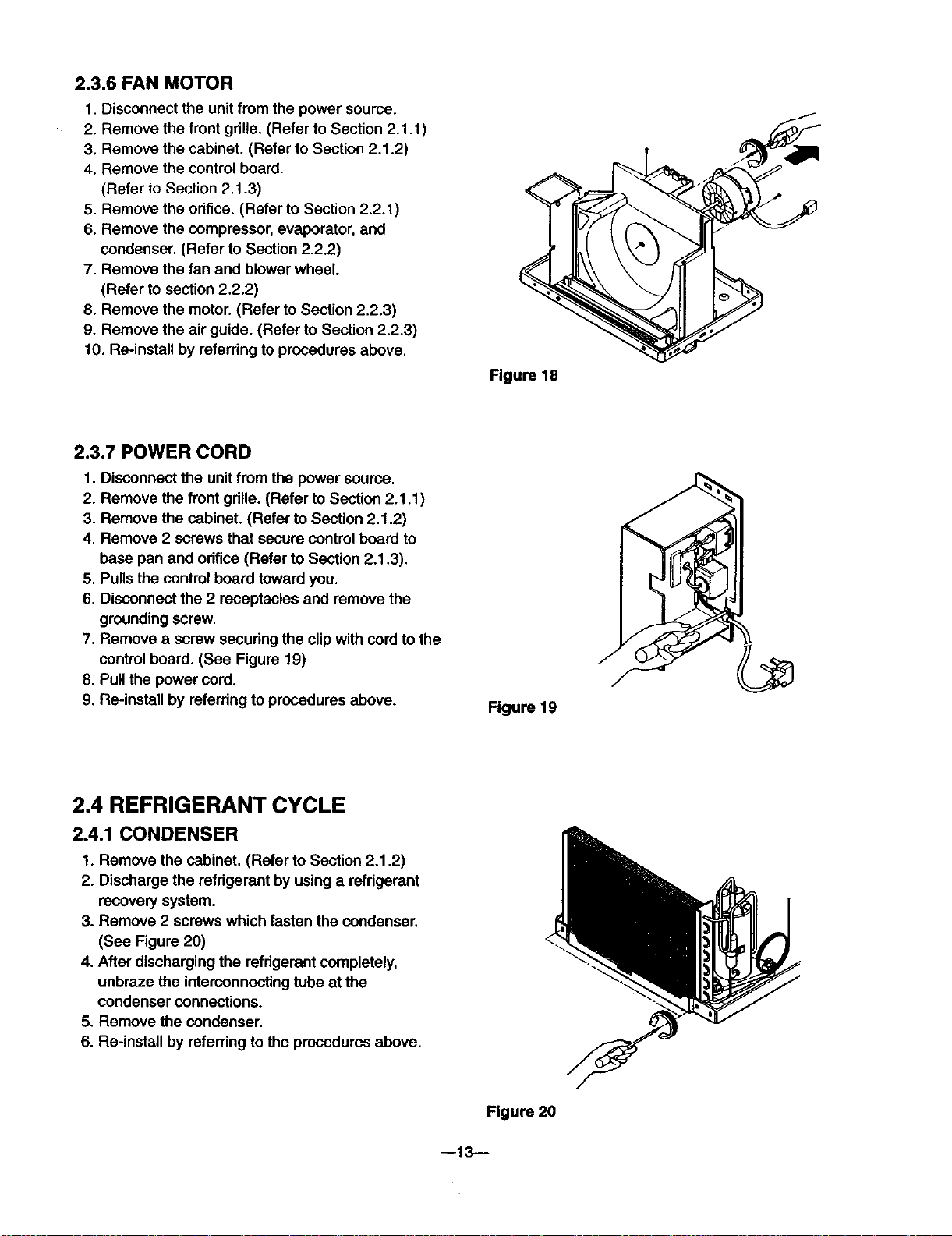
2.3.6 FAN MOTOR
1. Disconnect the unit from the power source.
2. Remove the front grille. (Refer to Section 2.1.1 )
3. Remove the cabinet. (Refer to Section 2.1.2)
4. Remove the control board.
(Refer to Section 2.1.3)
5. Remove the orifice. (Refer to Section 2.2.1)
6. Remove the compressor, evaporator, and
condenser. (Refer to Section 2.2.2)
7. Remove the fan and blower wheel.
(Refer to section 2.2.2)
8. Remove the motor. (Refer to Section 2.2.3)
9. Remove the air guide. (Refer to Section 2.2.3)
10. Re-install by referring to procedures above.
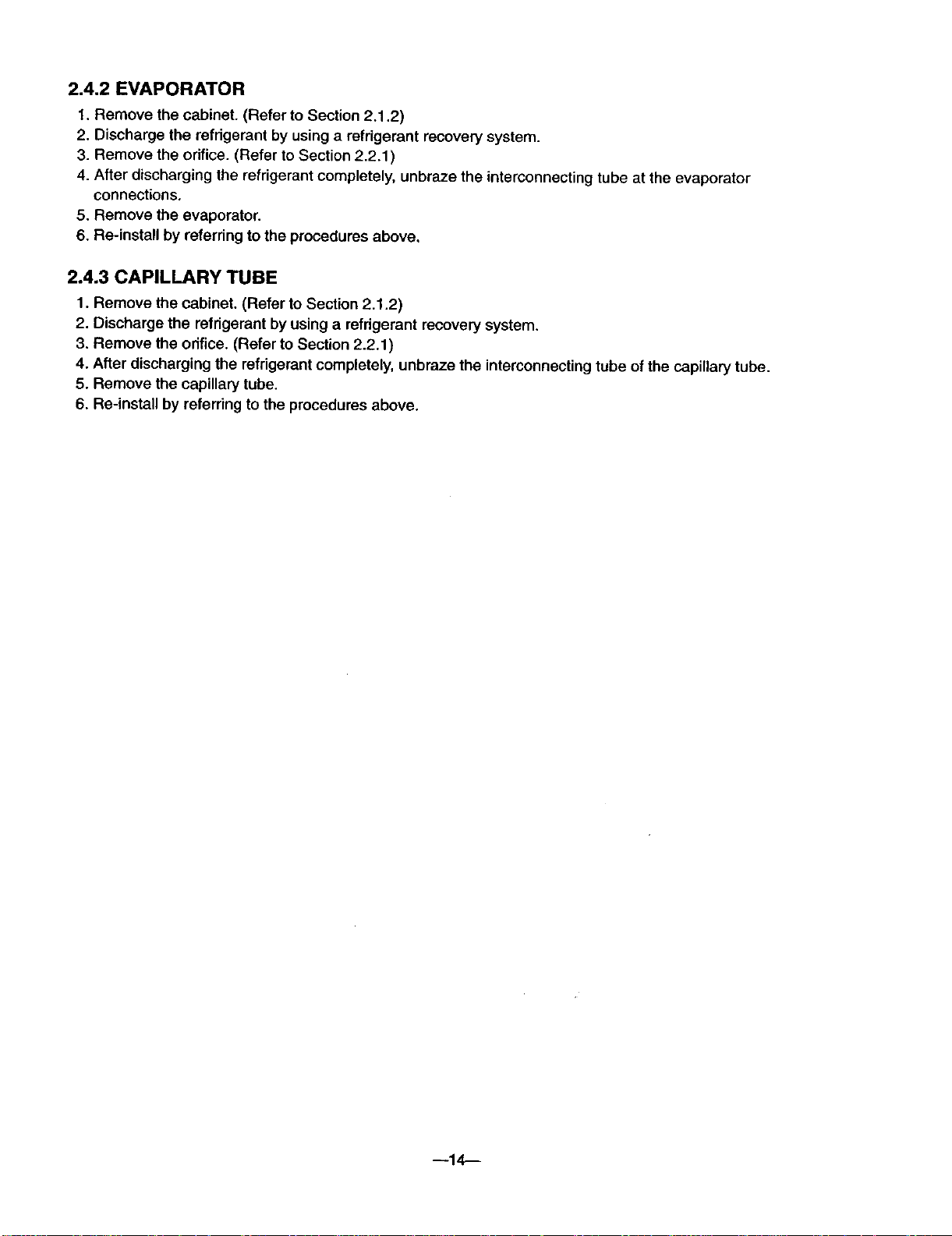
2.3.7 POWER CORD
1. Disconnect the unit from the power source.
2. Remove the front grille. (Refer to Section 2.1.1 )
3. Remove the cabinet. (Refer to Section 2.1.2)
4. Remove 2 screws that secure control board to
base pan and orifice (Refer to Section 2.1.3).
5. Pulls the control board toward you.
6. Disconnect the 2 receptacles and remove the
grounding screw.
7. Remove a screw secudng the clip with cord to the
control board. (See Figure 19)
8. Pull the power cord.
9. Re-install by referring to procedures above.
Figure 18
Figure 19
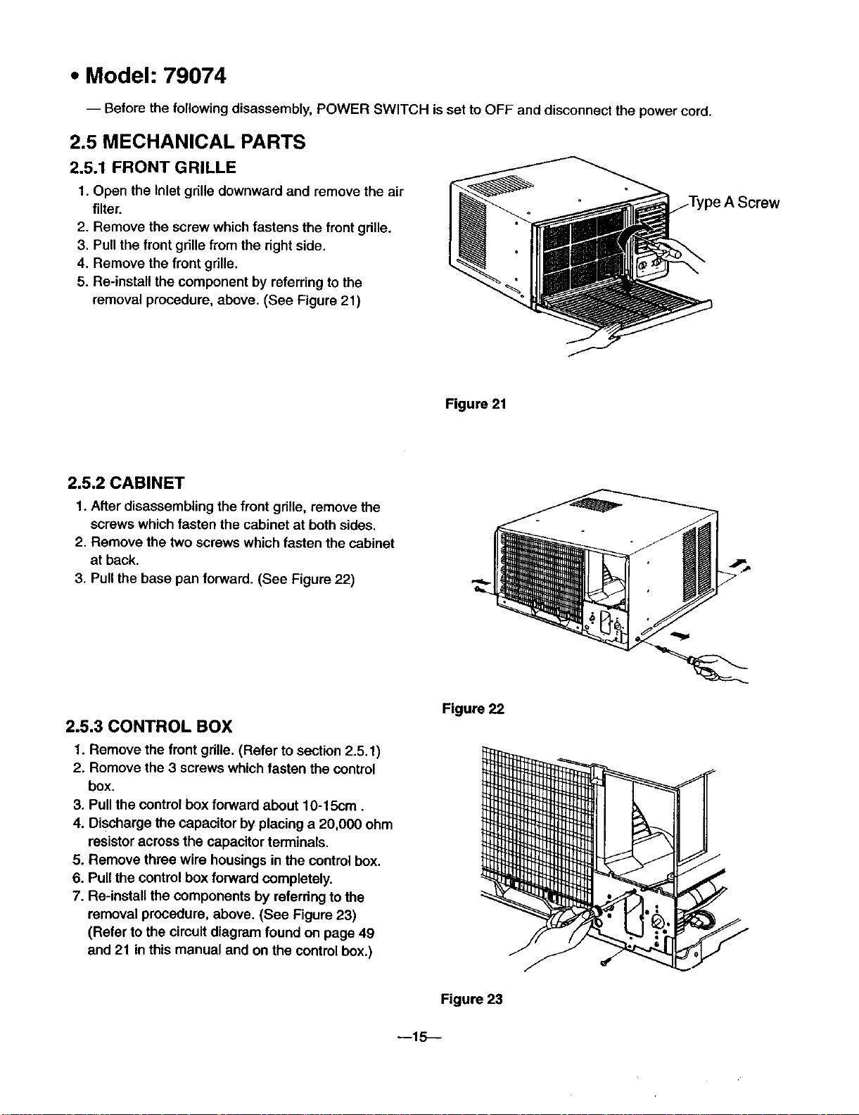
2.4 REFRIGERANT CYCLE
2.4.1 CONDENSER
1. Remove the cabinet. (Refer to Section 2.1.2)
2. Discharge the refdgerant by using a refdgerant
recovery system.
3. Remove 2 screws which fasten the condenser.
(See Figure 20)
4. After discharging the refrigerant completely,
unbraze the interconnecting tube at the
condenser connections.
5. Remove the condenser.
6. Re-install by referring to the procedures above.
Rgure 20
--13--
2.4.2 EVAPORATOR
1. Remove the cabinet. (Refer to Section 2.1.2)
2. Discharge the refrigerant by using a refrigerant recovery system.
3. Remove the orifice. (Refer to Section 2.2.1)
4. After discharging the refrigerant completely, unbraze the interconnecting tube at the evaporator
connections,
5. Remove the evaporator.
6, Re-install by referring to the procedures above,
2.4.3 CAPILLARY TUBE
1. Remove the cabinet. (Refer to Section 2.1.2)
2. Discharge the refrigerant by using a refrigerant recovery system.
3. Remove the orifice. (Refer to Section 2.2.1 )
4. After discharging the refrigerant completely, unbraze the interconnecting tube of the capillary tube.
5. Remove the capillary tube.
6. Re-install by referring to the procedures above.
--14--
• Model: 79074
-- Before the following disassembly, POWER SWITCH is set to OFF and disconnect the power cord.
2.5 MECHANICAL PARTS
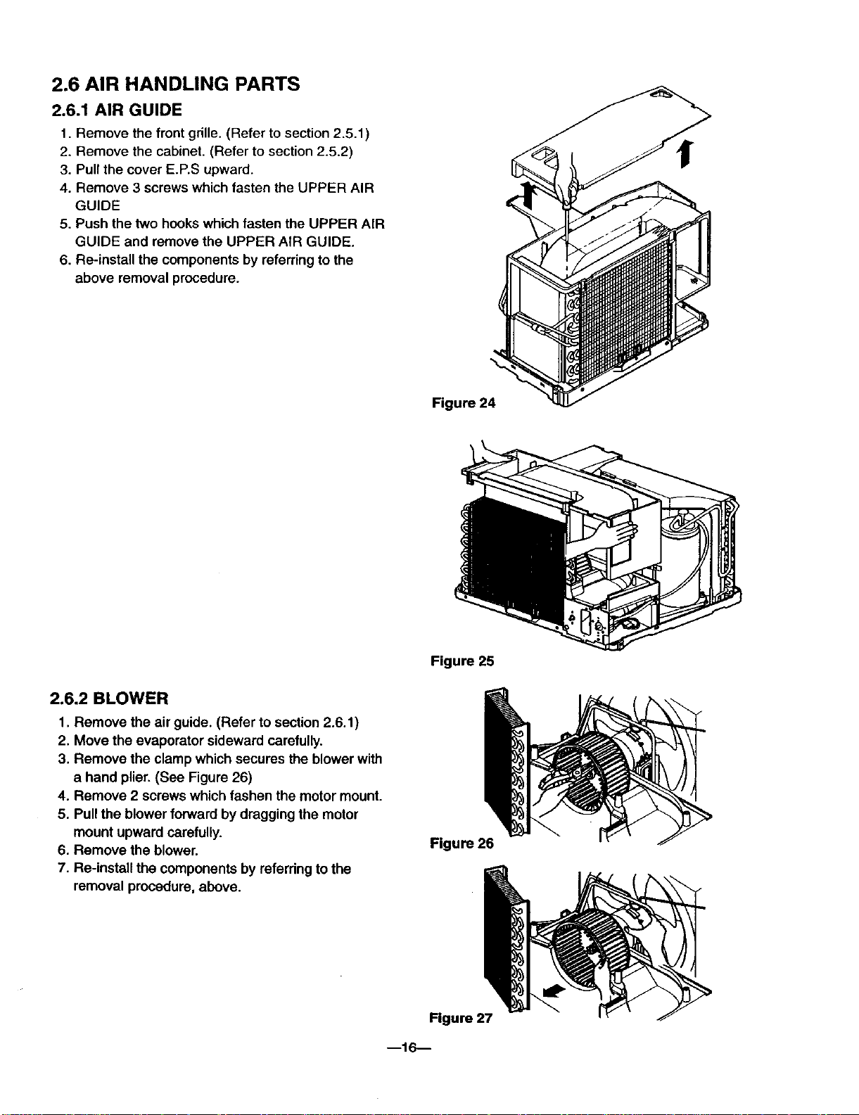
2.5.1 FRONT GRILLE
1. Open the Inlet grille downward and remove the air
filter.
2. Remove the screw which fastens the front grille.
3. Pull the front grille from the right side.
4. Remove the front grille.
5. Re-install the component by referring to the
removal procedure, above. (See Figure 21)
Figure 21
2.5.2 CABINET
1. After disassembling the front gdile, remove the
screws which fasten the cabinet at both sides.
2. Remove the two screws which fasten the cabinet
at back.
3. Pull the base pan forward. (See Figure 22)
2.5.3 CONTROL BOX
1. Remove the front grille. (Refer to section 2,5.1)
2. Romove the 3 screws which fasten the control
box.
3. Pull the control box forward about 10-15cm.
4, Discharge the capacitor byplacing a 20,000 ohm
resistoracross the capacitor terminals,
5. Remove three wire housings in the control box.
6. Pullthe control box forward completely.
7, Re-install the components by referring to the
removal procedure, above. (See Figure 23)
(Refer to the circuit diagram found on page 49
and 21 in this manual and on the control box.)
Figure22
--15_
Figure 23
2.6 AIR HANDLING PARTS
2.6.1 AIR GUIDE
1. Remove the front grille. (Refer to section 2.5.1)
2. Remove the cabinet. (Refer to section 2.5.2)
3. Pull the cover E.P.S upward.
4. Remove 3 screws which fasten the UPPER AIR
GUIDE
5. Push the two hooks which fasten the UPPER AIR
GUIDE and remove the UPPER AIR GUIDE.
6. Re-install the components by referring to the
above removal procedure.
Figure 24
2.6.2 BLOWER
1. Remove the air guide. (Refer to section 2.6.1)
2. Move the evaporator sideward carefully.
3. Remove the clamp which secures the blower with
a hand plier, (See Figure 26)
4. Remove 2 screws which fashen the motor mount.
5. Pull the blower forward by dragging the motor
mount upward carefully.
6. Remove the blower.
7. Re-install the components by referring to the
removal procedure, above.
Figure 25
Figure 26
Figure 27
--16---
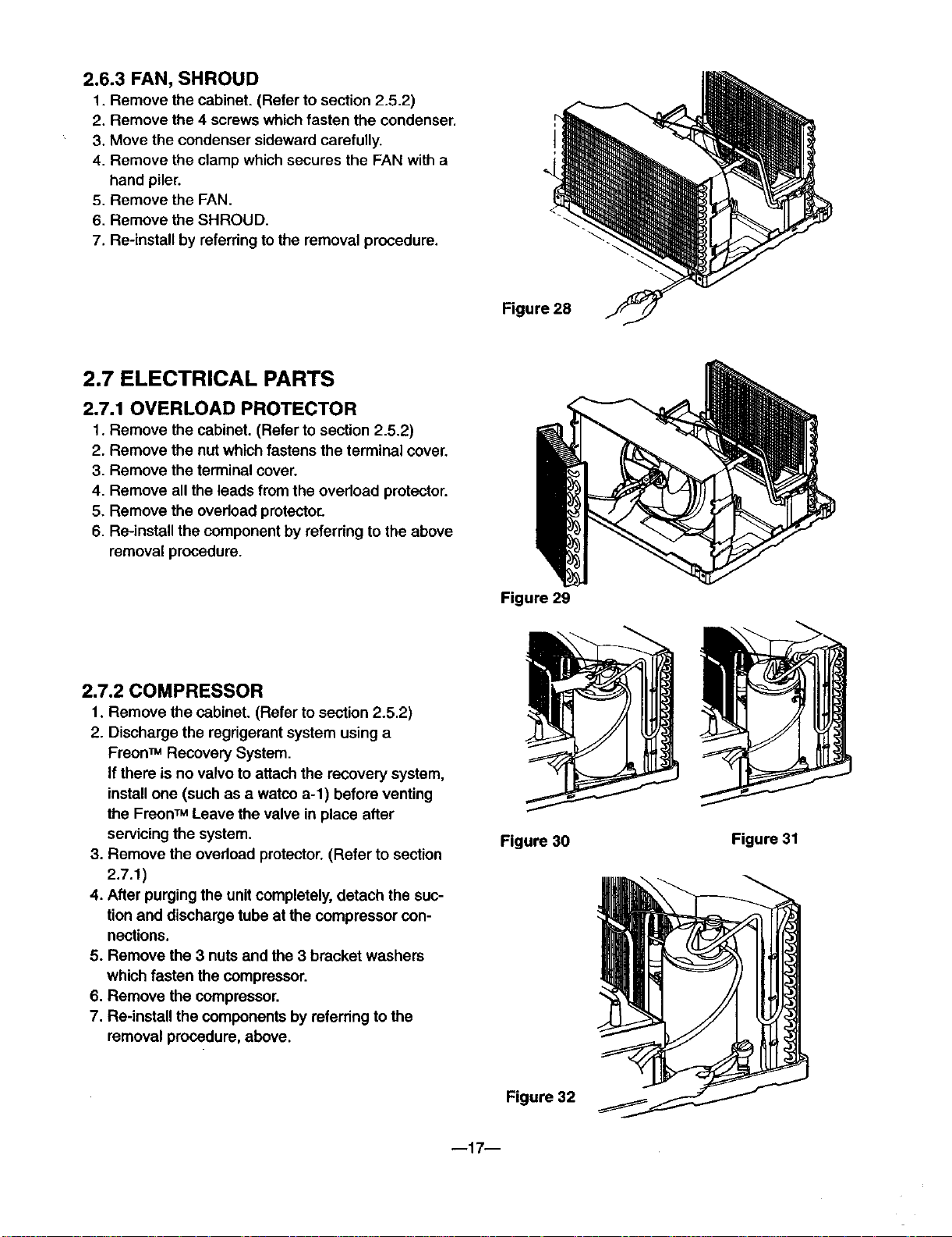
2.6.3 FAN, SHROUD
1. Remove the cabinet. (Refer to section 2.5.2)
2. Remove the 4 screws which fasten the condenser,
3. Move the condenser sideward carefully.
4. Remove the clamp which secures the FAN with a
hand plier.
5. Remove the FAN,
6. Remove the SHROUD.
7. Re-install by referring to the removal procedure.
2.7 ELECTRICAL PARTS
2.7.1 OVERLOAD PROTECTOR
1. Remove the cabinet. (Refer to section 2.5.2)
2. Remove the nut which fastens the terminal cover.
3. Remove the terminal cover.
4. Remove all the leads from the overload protector.
5. Remove the overload protecto_
6. Re-install the component by referring to the above
removal procedure.
Figure 28
2.7.2 COMPRESSOR
1. Remove the cabinet. (Refer to section 2.5.2)
2. Discharge the regdgerant system using a
FreonTM Recovery System.
If there is no valvo to attach the recovery system,
install one (such as a watco a-l) before venting
the FreonTM Leave the valve in place after
servicingthe system.
3. Remove the ovedoad protector. (Refer to section
2.7.1)
4. After purging the unit completely, detach the suc-
tion and discharge tube at the compressor con-
nections.
5. Remove the 3 nuts and the 3 bracket washers
which fasten the compressor.
6. Remove the compressor.
7. Re-install the components by referring to the
removal procedure, above.
Figure 29
Figure 30
Figure 31
m17--
Figure 32
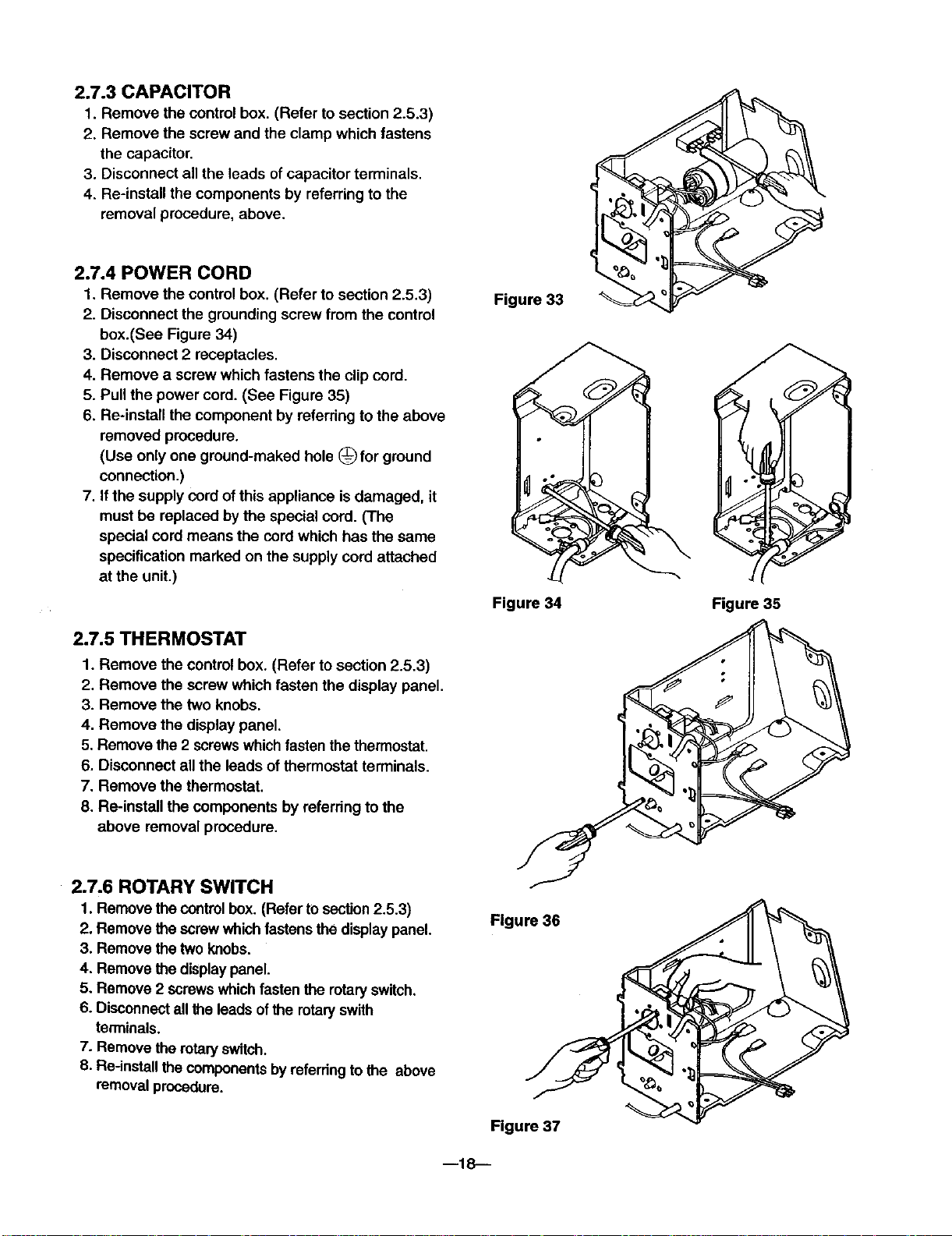
2.7.3 CAPACITOR
1. Remove the control box. (Refer to section 2.5.3)
2. Remove the screw and the clamp which fastens
the capacitor.
3. Disconnect all the leads ofcapacitor terminals.
4. Re-instan the components by referring to the
removal procedure, above.
2.7.4 POWER CORD
1. Remove the control box. (Refer to section 2.5.3)
2. Disconnect the grounding screw from the control
box.(See Figure 34)
3. Disconnect 2 receptacles.
4. Remove a screw which fastens the clip cord.
5. Pull the power cord. (See Figure 35)
6. Re-install the component by referring to the above
removed procedure.
(Use only one ground-maked hole (_ for ground
connection.)
7. If the supply cord of this appliance is damaged, it
must be replaced by the special cord. (The
special cord means the cordwhich has the same
specification marked on the supply cord attached
at the unit.)
Figure 33
Figure 34
Figure 35
2.7.5 THERMOSTAT
1. Remove the control box. (Refer to section 2.5.3)
2. Remove the screw which fasten the display panel.
3. Remove the two knobs.
4. Remove the display panel.
5. Remove the 2 screws whichfasten the thermostat.
6. Disconnect all the leads ofthermostat terminals.
7. Remove the thermostat.
8. Re-install the components by referring to the
above removal procedure.
2.7.6 ROTARY SWITCH
1. Remove the controlbox. (Refer to section2.5.3)
2. Remove the screw which fastensthe display panel.
3. Remove the two knobs.
4. Remove the displaypanel.
5. Remove 2 screws whichfastenthe rotaryswitch.
6. Disconnect all the leads ofthe rotaryswith
terminals.
7. Remove the rotaWswitch.
8. Re-install the componentsby referringto the above
removal procedure.
Figure 36
m18--
Figure 37
2.7.7 MOTOR
1. Remove the cabinet. (Refer to section 2.5.2)
2. Remove the air guide. (Refer to section 2.6.1)
3. Remove the blower, (Refer to section 2.6.2)
4. Remove the fan. (Refer to section 2.6.3)
5, Remove the shroud. (Refer to section 2.6.3)
6, Remove the control box. (Refer to section 2.5.3)
7, Remove the 2 screws which fasten the motor.
8. Remove the motor.
9. Re-install the components by referring to the
above removal procedure,
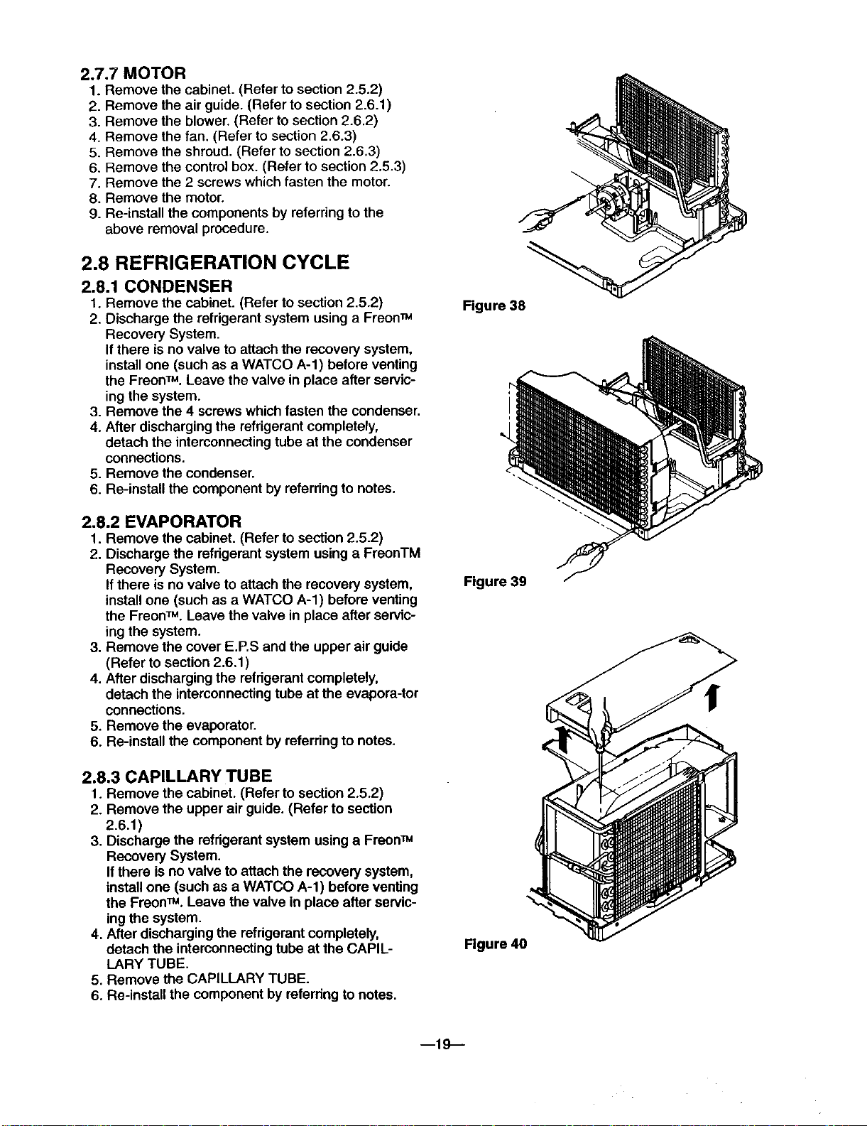
2.8 REFRIGERATION CYCLE
2.8.1 CONDENSER
1. Remove the cabinet. (Refer to section 2.5.2)
2. Discharge the refrigerant system using a Freon_
Recovery System.
If there is no valve to attach the recovery system,
install one (such as a WATCO A-l) before venting
the FreonTM. Leave the valve in place after servic-
ing the system.
3. Remove the 4 screws which fasten the condenser.
4. After discharging the refrigerant completely,
detach the interconnecting tube at the condenser
connections.
5. Remove the condenser.
6. Re-install the component by referring to notes.
Figure 38
2.8.2 EVAPORATOR
1. Remove the cabinet. (Refer to section 2.5.2)
2. Discharge the refrigerant system using a FreonTM
Recovery System.
If there is novalve to attach the recovery system,
install one (such as a WATCO A-l) before venting
the FreonTM. Leave the valve in place after servic-
ing the system.
3. Remove the cover E,P.S and the upper air guide
(Refer to section 2.6.1)
4. After discharging the refrigerant completely,
detach the interconnectingtube at the evaporator
connections.
5. Remove the evaporator.
6. Re-install the component by referring to notes.
2.8.3 CAPILLARY TUBE
1. Remove the cabinet. (Refer to section 2.5.2)
2. Remove the upper air guide. (Refer to section
2.6.1)
3. Discharge the refrigerant system using a Freon_
Recovery System.
Ifthere is no valve to attach the recovery system,
install one (such as a WATCO A-l) before venting
the FreonTM. Leave the valve in place after servic-
ingthe system.
4. After discharging the refrigerant completely,
detach the interconnecting tube at the CAPIL-
LARY TUBE.
5. Remove the CAPILLARY TUBE.
6. Re-install the component by referring to notes.
Figure 39
Figure 40
m19--
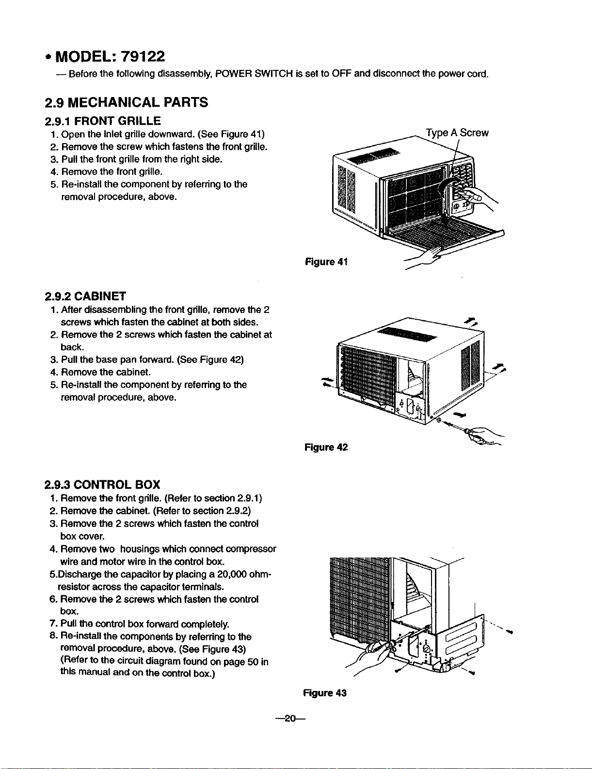
• MODEL: 79122
-- Before the following disassembly, POWER SWITCH is set to OFF and disconnect the power cord.
2.9 MECHANICAL PARTS
2.9,1 FRONT GRILLE
1. Open the inlet gdlle downward. (See Figure 41)
2. Remove the screw which fastens the front gdlle.
3. Pull the front gdlle from the right side.
4. Remove the front gdlle.
5. Re-install the component by referring to the
removal procedure, above.
Figure 41
2.9.2 CABINET
1. After disassembling the frontgdlle, remove the 2
screws which fasten the cabinet at both sides.
2. Remove the 2 screws which fasten the cabinet at
back.
3. Pull the base pan forward. (See Figure 42)
4. Remove the cabinet.
5. Re-install the component by referring to the
removal procedure, above.
Type A Screw
2.9.3 CONTROL BOX
1. Remove the front gdlle. (Refer to section 2.9.1 )
2. Remove the cabinet. (Refer to section 2.9.2)
3. Remove the 2 screws whichfasten the control
box cover.
4. Remove two housings which connect compressor
wire and motor wire in the control box.
5.Discharge the capacitor by placing a 20,000 ohm-
resistor across the capacitor terminals.
6. Remove the 2 screws which fasten the control
box.
7. Pull the control box forward completely.
8. Re-install the components by referring to the
removal procedure, above. (See Figure 43)
(Refer to the circuit diagram found on page 50 in
this manual and on the controlbox.)
Figure 42
Rgure 43
--20--
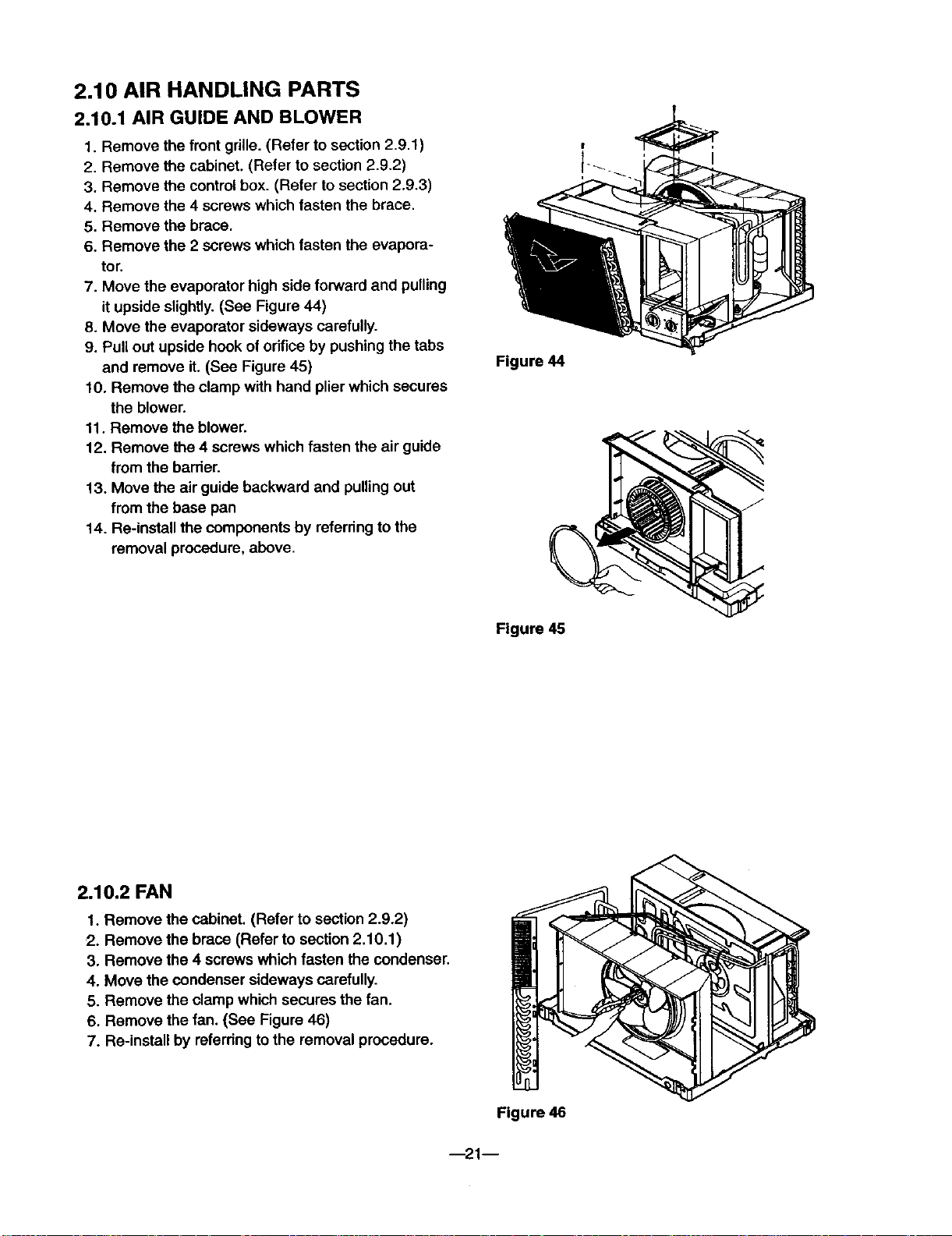
2.10 AIR HANDLING PARTS
2.10.1 AIR GUIDE AND BLOWER
1, Remove the front grille. (Refer to section 2.9.1)
2. Remove the cabinet, (Refer to section 2.9.2)
3. Remove the control box. (Refer to section 2.9,3)
4. Remove the 4 screws which fasten the brace,
5. Remove the brace.
6. Remove the 2 screws which fasten the evapora-
tor.
7. Move the evaporator high side forward and pulling
it upside slightly. (See Figure 44)
8. Move the evaporator sideways carefully.
9. Pull out upside hook of orifice by pushing the tabs
and remove it. (See Figure 45)
10. Remove the clamp with hand plier which secures
the blower.
11. Remove the blower.
12. Remove the 4 screws which fasten the air guide
from the barrier.
13. Move the air guide backward and pulling out
from the base pan
14. Re-install the components by referdng to the
removal procedure, above.
Figure 44
/
2.10.2 FAN
1. Remove the cabinet. (Refer to section 2.9.2)
2. Remove the brace (Refer to section 2.10.1)
3. Remove the 4 screws which fasten the condenser.
4. Move the condenser sideways carefully.
5. Remove the clamp which secures the fan.
6, Remove the fan. (See Figure 46)
7. Re-install by referdng to the removal procedure.
Figure 45
--21--
Figure 46
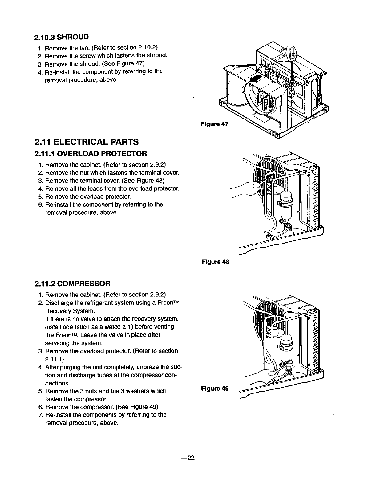
2.10.3 SHROUD
1. Remove the fan. (Refer to section 2.10.2)
2. Remove the screw which fastens the shroud.
3. Remove the shroud. (See Figure 47)
4. Re-install the component by referring to the
removal procedure, above.
2.11 ELECTRICAL PARTS
2.11.1 OVERLOAD PROTECTOR
1. Remove the cabinet. (Refer to section 2.9.2)
2. Remove the nut which fastens the terminal cover.
3. Remove the terminal cover. (See Figure 48)
4. Remove all the leads from the ovedoad protector.
5. Remove the overload protector.
6. Re-install the component by referring to the
removal procedure, above.
Figure 47
2.11.2 COMPRESSOR
1. Remove the cabinet. (Refer to section 2.9.2)
2. Discharge the refrigerant system using a Freon_
Recovery System.
If there is no valve to attach the recovery system,
install one (such as a watco a-l) before venting
the FreonTM.Leave the valve in place after
servicing the system.
3. Remove the overload protector. (Refer to section
2.11.1)
4. After purging the unit completely, unbraze the suc-
tion and discharge tubes at the compressor con-
nections.
5. Remove the 3 nuts and the 3 washers which
fasten the compressor.
6. Remove the compressor. (See Figure 49)
7. Re-install the components by referring to the
removal procedure, above.
Figure 48
Figure 49
--22D
 Loading...