

Page 1
Owner^s Manual
Manual dal Propietario
KenmorG
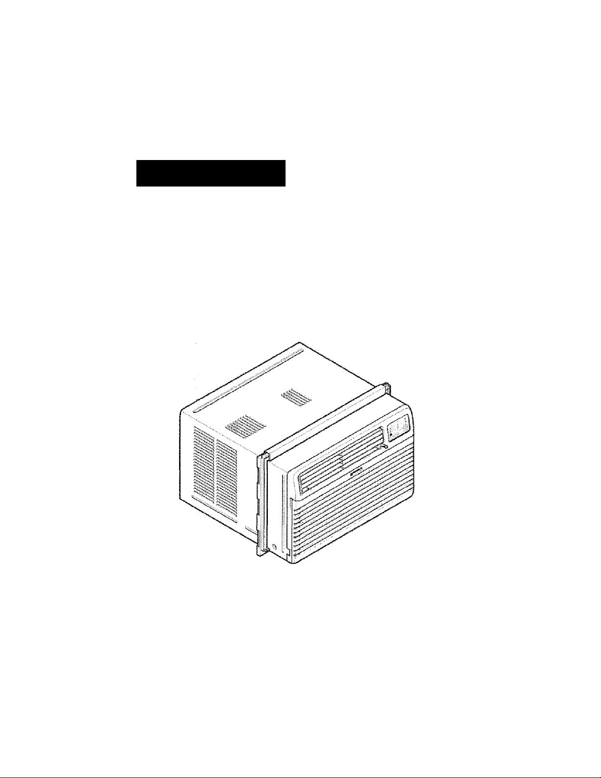
ROOM MR CONDITIONER
ACONDICIONADOR DE AIRE DE VENTANA
Model, Modelo 580.76100
DIstríbyW by Sears, Roebuck and Co., Hofman Estati», !L 60179
www.sears.COTn
Page 2

TABLE OF CONTiNTS
TABLE OF CONTENTS
WARRANTY
SAFETY
fmporteni Safety instructions"*’—'-"--*............................3
.......................................
......................................
..........................
2
3
ELECTRICAL REQUIREMENTS..........4
INSTALLING THE POWER CORD
INSTALLATION
Installation Requirements
Installation
How to Install.............................................................. ®
Removal frcrni Window
.....................................
.............................................
.................................................................
...........................................
.....
4
&
6
8
OPERATION...............................................................9
How and Why.....................................................*.........
Normal Sounds
Capacity and Running Time
...............
—...............*
.........................*...............
.........
..........9
2
®
9
-9
Features.................................................................... =10
Using the Air Conditioner............................................ 10
Control Panel
Remote Control
MAINTENANCE
Air Filter Cleaning-—”
Air Conditioner Cleaning
How to Remove the Front Grille
How to Replace the Front Grille
TROUBLESHOOTING".
Before Calling for Service
ESPANOL
........................*..................................
...........................................................
......................................................
............................. .................
..............................................
....................................
....................................
..................
.............................................
..................
-.........................
MASTER PROTECTION
AGREEMENTS
........................................................
SERVICE NUMBERS --Back Cover
11
12
13
—13
13
13
13
.14
14
15
30
WARRANTY
FULL ONE YEAR WARRANTY ON
ROOM AIR CONDITIONER
For one year from the date of purchase, when this
air conditioner is operated and maintained for
normal room cooling according to the instructions
in this owner's manual, Sears vs^il lepair this air
conditioner, free of charge, ff defective irt material or
workmanship.
FULL FIVE-YEAR WARRANTY ON
SEALED REFRIGERATION SYSTEM
For five years from the date of purchase, when this
air conditioner is operated and maintained for
normal room cooling areordlng to the instructions
in this owner's manual, Sears will repair the sealed
refrigeration system (consisting of refrigerant,
connecting tuWng, and compressor), free of charge,
if defective In material or workmanship.
WARRANTY SERVICE IS AVAILABLE BY
CONTACTING SEARS SERVICE AT
1-800-4-MY-HOME®.
Warranty coverage applies onfy to air conditioners
used for non-commercial, private household
purposes.
This warranty applies only «rtilie this product is in
use m the United States.
This warranty gives you specific legal rights, and
you may also have other right which vary from state
to state.
KlilribiiMl ^ Seam, Rosbudc aiici Cki.,
-2-
Page 3
SAFETY
iMPORTANT SAFETY INSTRUCTIONS
The safety instructions bsiow will tell you how to use your room air conditioner to avoid harm to yourself or
damage to your ROOM AIR CONDiTiONER.
FOR YOUR SAFETY
Do not store or use gasoline or other flammable
vapors and liquids in the vicinity of this or any other
appliance. Read product labels for flammability and
other warnings.
.................. PREVENT ACCIDENTS
AWARN!Nd
To reduce the risk of fire, electrical shock, or injury
to persons when using your air conditioner, follow
basic precautions, inciuding the following:
• Be sure toe eiectrica! service is adequate for the
model you have chosen.
• If the air conditioner is to be installed In a window,
you will probably wartt to dean both sides of the
glass first. If toe window is a triple-track type with a
screen pane! inducted, you may want to remove
the screen completely before installation,
• Be sure the air conditioner has been securely and
correctly installed according to the separate
installation instructions provided wito this manual.
Save tois manual and installation instructions for
possible future use in removing or reinstalling this
unit.
• Use gloves when handling tie шг conditioner.
Be careful to avoid cuts from sharp metal fins on
front and rear coils.
шШШ
The complete electrical rating of your new room air
conditioner is stated on the serial plate. Refer to the
rating «toen checking the eiectrica! requirements.
" Be sure the air conditioner is properly grounded.
To minimize shock and fire hazards, proper
grounding is important. The power cord is
equif^ed vwth a three-prong grounding plug for
protection against shock hazards.
• Your air conditioner must be plugged into a
property grounded w^l reoeprtacle. if the wall
rec^tade you intend to use is not adequately
grounded or protected by a time delay fuse or
circuit breaker, have a qualified eieotridan install
the proper receptacle,
• Do not run air conditioner with a protective
covering. This could result in mechanical damage
within the aJr conditioner.
ELECTRICAL INFORMATION
> Do not use an esdension coifo or an adapter
plug.
Do not an extension cord or an adapter plug.
Do not remove any prong from the power cord.
cord
ENIRSY SAVING IDEAS
• The capacity of toe room air conditioner must fit
the room size for efficient and satisfactory
operation,
• install the room air conditioner on the shady side
of your home. A window that faces north Is best
because it is shaded most of the day.
• Do not block air conditioner flow inside with biinds,
curtains, or furniture, or outside with shrubs,
endosures, or other buildings.
• Close toe floor and wail registers and the fireplace
damper so cool air does not escape up the
chimney or into the duct work,
® Keep biinds and drapes in other windows closed
during the surtniest part of the day.
»Clearr the air filter as recommended in the
MAiNTCNANCE section of this manual.
■ Proper Insulation and weather stripping in your
home will help keep warm air out and cool air In,
• External house shading with trees, plants or
awninp wi!i help reduce the ^rcondittoiief's work
load.
• Operate heat producing appliances such as
ranges, washers, dryers, and dishwashers during
toe coolest part of the day.
; Avoid fire hazard or electric shock.
-3'
Page 4
ELECTRICAL REQUIREMENTS
OBSERVE ALL LOCAL CODES AND
ORDINANCES.
DO NOT, UNDER ANY CIRCUMSTANCES,
REMOVE THE POWER SUPPLY CORD
GROUND PRONG,
ELECTRICAL GROUND IS REQUIRED ON
THIS APPLIANCE.
A 2S0“VOlt 60 Hz, AG only, 2QA fused and
properly grounded electrical supply is required.
A time delay fuse or time delay circuit breaker
is recommandeti. Use a dedicated dreuft,
serving only this appliance.
DO NOT USE AN EXTENSION CORD.
115V-
NCyfE! The shape may be dlferent acoording to its rttodei.
Use Wall Receptacle
Standard 125 V,
Power Supply
fl V) grounding
\ H y recaptacl» mtad
/"■ X standard 2S0V,
f»“ *«" ] a-wire grawnding
1 ^ ; ?eü*pteds rated
/ 1 mn\ 3-wire grounding
i ~ J reœptaas rated
1SA, IffiVAC
15A,K30VAC
Standard 250V,
20A,asOVAC
Us® Î5 AMPdime
delay fuse or IS AMP,
elKsutt breafter.
Use 20 AMP. time
(Way fuse or 20 MAP.
offciifebfeaitar.
230V-
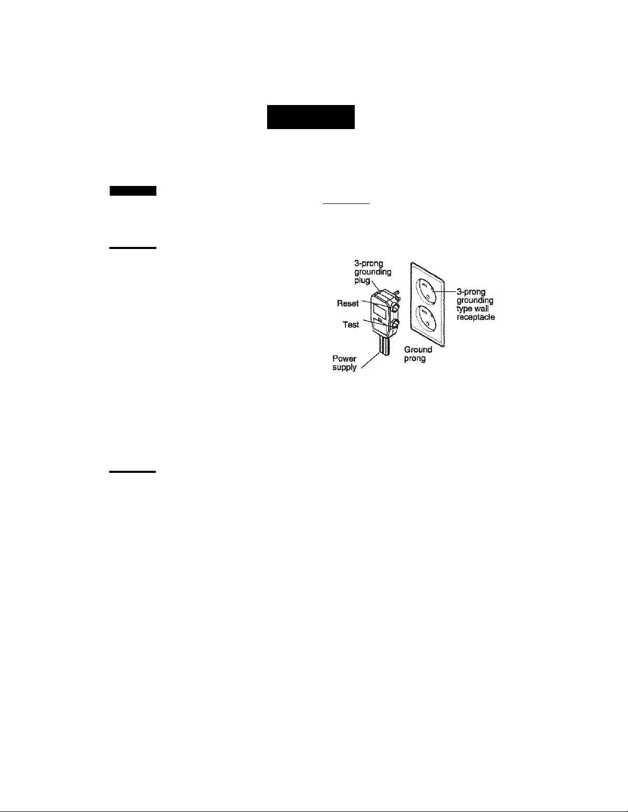
RECOMMENDED GROUNDING METHOD
For your personal safety, this appliance must
be grounded. This appiiance has a power
supply cord with a 3-prong grourrding plug. To
minimize possible shock hazard, the cord must
be plugged into a mating grounding type wall
receptacle and grounded in acoardaiic® with
the National Electrical Code {ANSI/NFPA 70)
latest edition and all local codes and
ordinances, if a mating wall receptacle is not
available, it is the personal responsibility and
obligation of the customer to have a property
grounded 3-prong wail receptacle Installed by a
qualified eiectrician.
Power ootid may irrdude a currant interrupter
device. A test arid reset butt!» is provided on the
piuo case. Th« device ^oulcf be isstad on a
psfiixlk! basis by first prassins the TEST hufttm
and Biart th® RESET butiort. If tte TEST button:
(toes not Wp or it the RESET button will not slay
engaged, dlscorstlnue use of the air oonditiorter a:nd
contact a. qualified service techntaian.
^WAMNG
Efestrloitt Shock Hazard
Plug into a grosjided 3 prong outlst.
Do not remove grounet prong.
Do not use an adapter.
Do not use an extension oord.
Failure to fellow these instructions can rssuK in
death fire or ©lacWca! shock
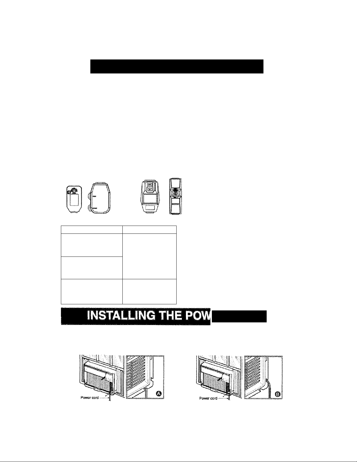
ER CORD
You can choose between two methods below according to your window stool shape and preference.
USING SLIT “A" USING SLIT "B"
Fasten the stopper using 1 screw holes, and lead
out !he power cord through slit "A",
Fasten the stopper using toft screw hole, and rotate
properly to lead the power cord out through silt *B”.
-4-
Page 5
INSTALLATION
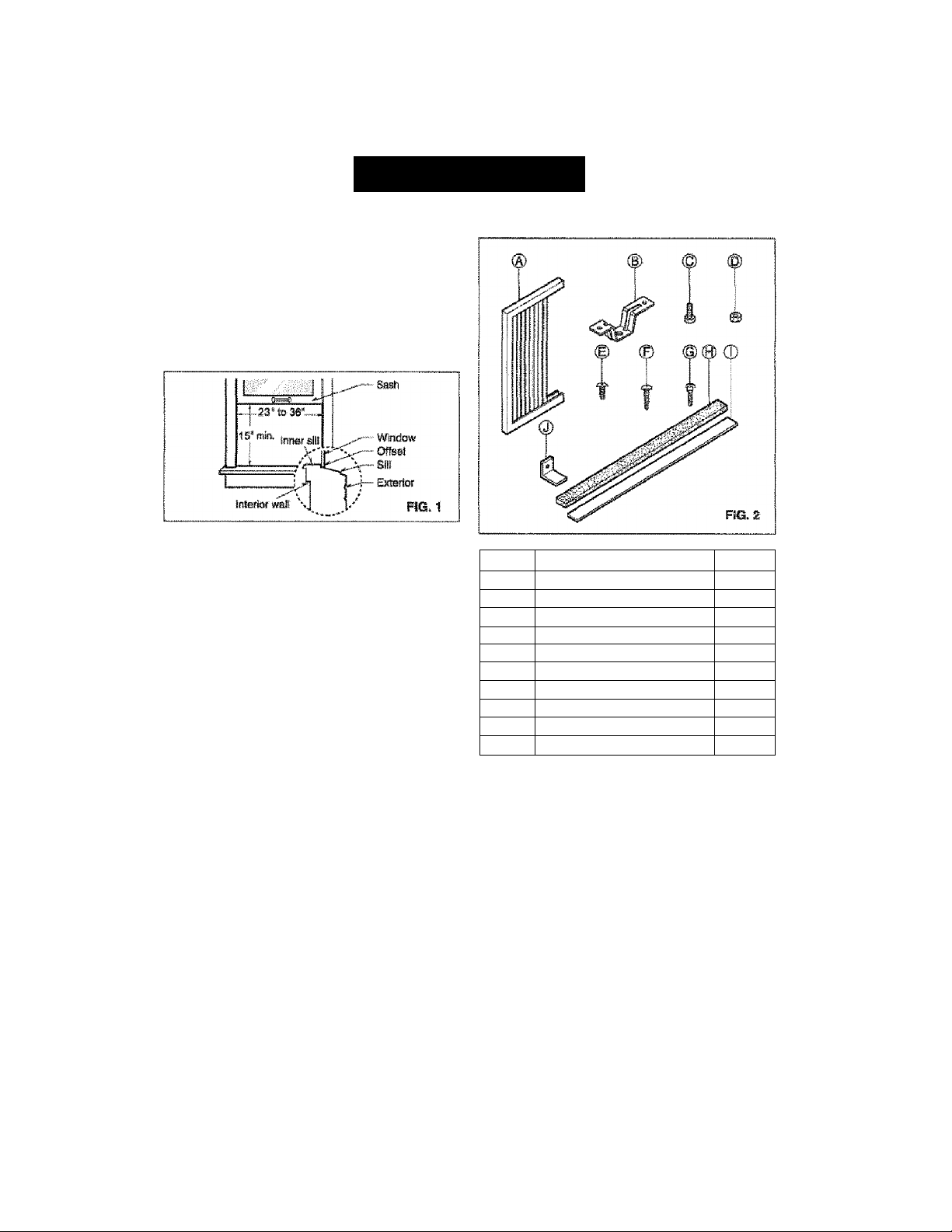
INSTALLATION REQUIREMENTS INSTALLATION HARDWARE
Your air condlliotier wil Ifisteft into stancbfd ctotiWe hursg
windows wifi actual clear opaning wiciis of 23 to 38 inches
(584mm to 914mm) (RG. 1).
Lower sash must open suffictently to allow a clear
vertical opening of 15 inches (381mm). Side louvers
and the rear of the air conditiotier must have dear
air space to allow enough airflow through the
condenser for heat removal, The rear of the unit
must be outdoors, not inside a building or garage.
ELECTRICAL SERVICE
Check your av^iiabte electrital service. The power
supply available must be the same as that shown
on the unit nameplate (iound on right side of cabinet).
AH models are ecfuipped with a S^irong service plug
t) provide proper service and safe positive
grounding. Do not chKigs plug in; any way. Do. not
use an adapter plug. If your present wail outlet does
not match your pli^, call a qualified electrician to
mate the necessary correc^ons.
SAVE CARTON and this OWJER'S MANUAL for
future reference. The canon Is the best way to store
Unit during winter or when riot In use.
ITERS
A
NAME OF PARTS Q'TY
SIDE CURTAiN
в SILL SUPPORT
c BCDLT
D LOCK NUT
E
SCREW; 2SiB4“
p
SCREW: 5/8"
e
SCREW: 5/8"
H FOAM STRIP
1
FOAM SEAL 1
L BRACKET 1
j
2
2
2
2
13
3
5
1
To avoid risk of personal injury, property damage,
or product damage due to toe weight of this
device and sharp edges toai may be exposed:
‘ Air conditioners covered in tois manual pose an
excessive weight hazard. Two or more peopfe
are needed to move and ittotaif the unit.
To prevent Injury or strain, ше proper Bfting and
carrying tertoniques when moving uni.
» Carefully IrtsiMci iocalion where sir tondiitoner
will be installed, Be sure it will support the
weight of toe unit over an extended period of
ime.
• Handle air conditioner with care. Wear
protective gloves whenever llffing or carrying toe
unit. AVOiD toe sharp meiaf fins of front and
rear cdls.
* Make sure air conditioner does not fall during
instellation.
REQUIRED TOOLS:
• Tight Fitting gloves
«Standaid screwdriver
• Philips screwdriver
• Pliers
• Sharp knife
• 3/84nch open end wrench or adjustable wrench
• 1 /4-ineh hex socket and ratehat
"Tape measure
• Eiectrfc drill
• 1/4-tnch drill bit
-5-
Page 6
NSTALLATION
INSTALLATION
Pick a iocatiori which wi allow you io blow the ooid
air into the area you want Windows used for
instaHation must be strong ertou^ to support the
weight of the air conditioner. Qood instaiiation with
special attention to the proper position of ttie unit
will lessen the tttance that service will be needed.
When cooling more than one room, instaliatfon
location is very importartt To coo! your rooms, cold
air most be blown from fie air conditioner in a
straight path.
HOW TO INSTALL
If the air conditioner is blocked by & storm
window frame, see step 19 on |oage S before
1001118 to Install.
Remove the screws which fasten the cabinet at
0
both sides and at the back. Save side screws.
Discard back screws.
window inner sill.
Carefully place the cabinet on the vwntlow toner sill
and align the center of cabinet front «iti the cerster
line marired in the Mndow inner si.
SiWe the unit out of the cabiret by gripping the
! pan handle and puli forward while bracing the
a
cabinet.
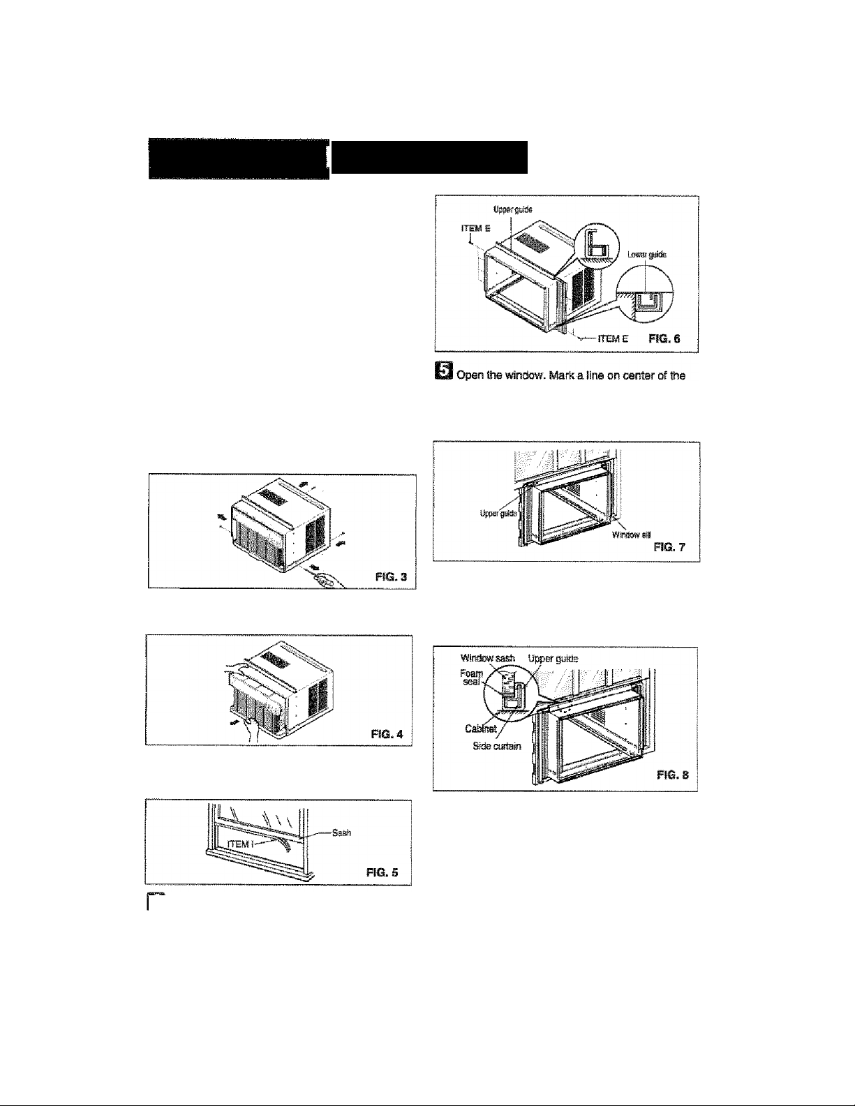
Q Cut the fOm SEAL (ITEM I) to fit the
underside of the window sash. Peei off the backing
and attach toe FOfM SEAL as shown in Fig. 5.
hbf insert the side curtain ffTEM A) Wo ths upper
guide and lower guide of the air contfMofter. Fasten
the curtains to the unit with screws |ITEM E).
m
Puli the bottom window sash down behind fie
upper puida until they meet.
MOTE; Do not puli ths window sash down so tightly
toatths movement of side curtain is restricted.
mm Loosely assemble the si supports using the
parts in FK3.9,
INDOOR
\sJ I
•ITEMO
ÌTEMC
QyypQQp
ITEM6
FIG. 9
-6-
Page 7
NSTALLATION
m Select the position that will place the sill supports
near the outermost point on sill (FIG. 10).
Attach the sill supports to the cabinet track hole
ctosest to the setected posioti using screw (ITEM E).
rrews
1
B®0C«
Place the si supports with the cabinet on the
H
window sill's sslected: frasitlon.
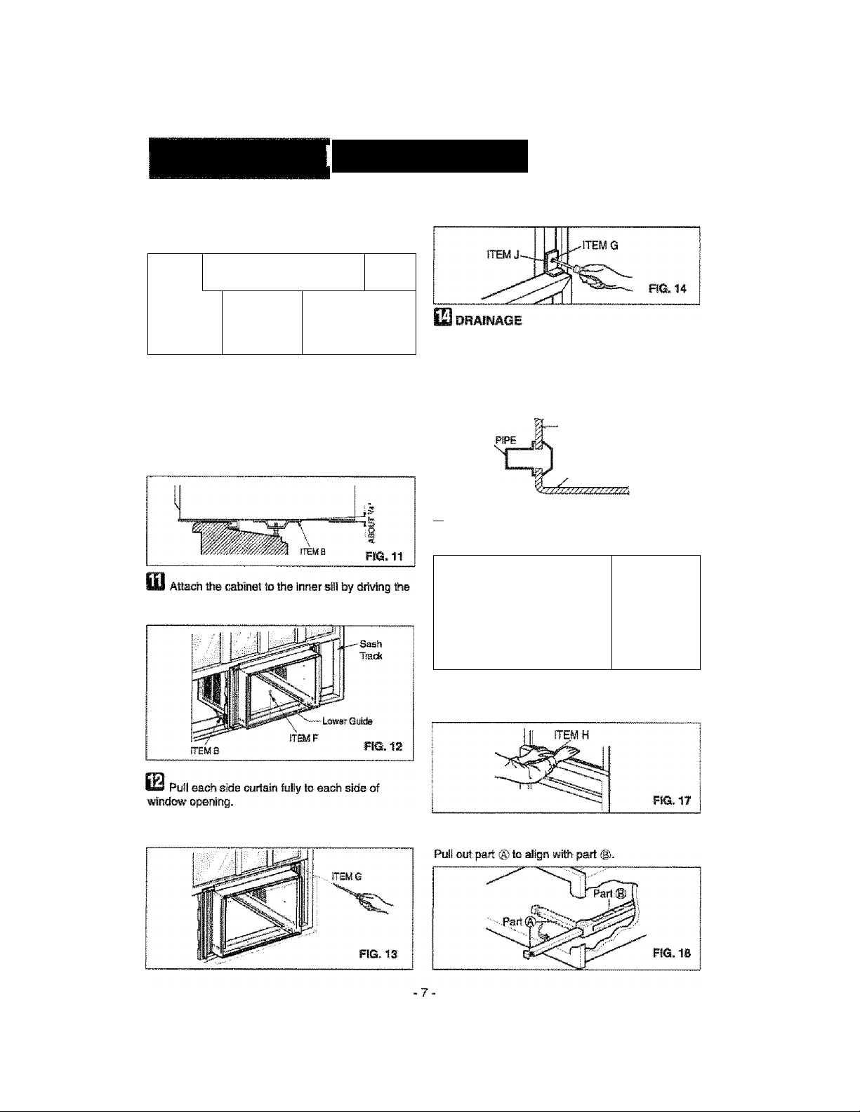
The cabinet should be installed with a vary
slight tilt (aboiJ 1/4") downward toward the outside
(FIG. 11).
Adjust toe bolts and the nuts of si supports to level
toe catoinet.
screws (ITEM F) through the Lower Guide into the
window inner si (FIG. 12).
^
................. ...............................
£
1
# /
t f
1
OuTOOfi
...Ì ^
FIG. 10
if Attach the L BRACKET (ITEM J) with screw
(ITEM G), (FIG. 14)
Be sure to insert the drain pipe into base pan before
installafion.
The air condloner must be installed with a stlght tilt
(1/4') downward to the outside for proper drainage of
excess condensed' water toraugh the drain pipe.
(RG. 15)
BASE PAN REAR
DRAIN
BASE PA« BOTTOM
FIG. 15
IP Slide the chassis into the cabinet. (FIG. 18)
CAUTION; For ssourtty purposes, reinstall side
screws you removed In step 1.
Attach each side curtain to the window sash using
screws (ITEM G). (FIG. 13)
^ FÌG. IS
22 Cot tos: foam strip (ITEM H) to the proper length
afw insert between the upper window sash and the
lower window sash. {FIG. 17)
The vent control handle must be straightened
ire the decorative front is attached.
K
Page 8
INSTALLATION
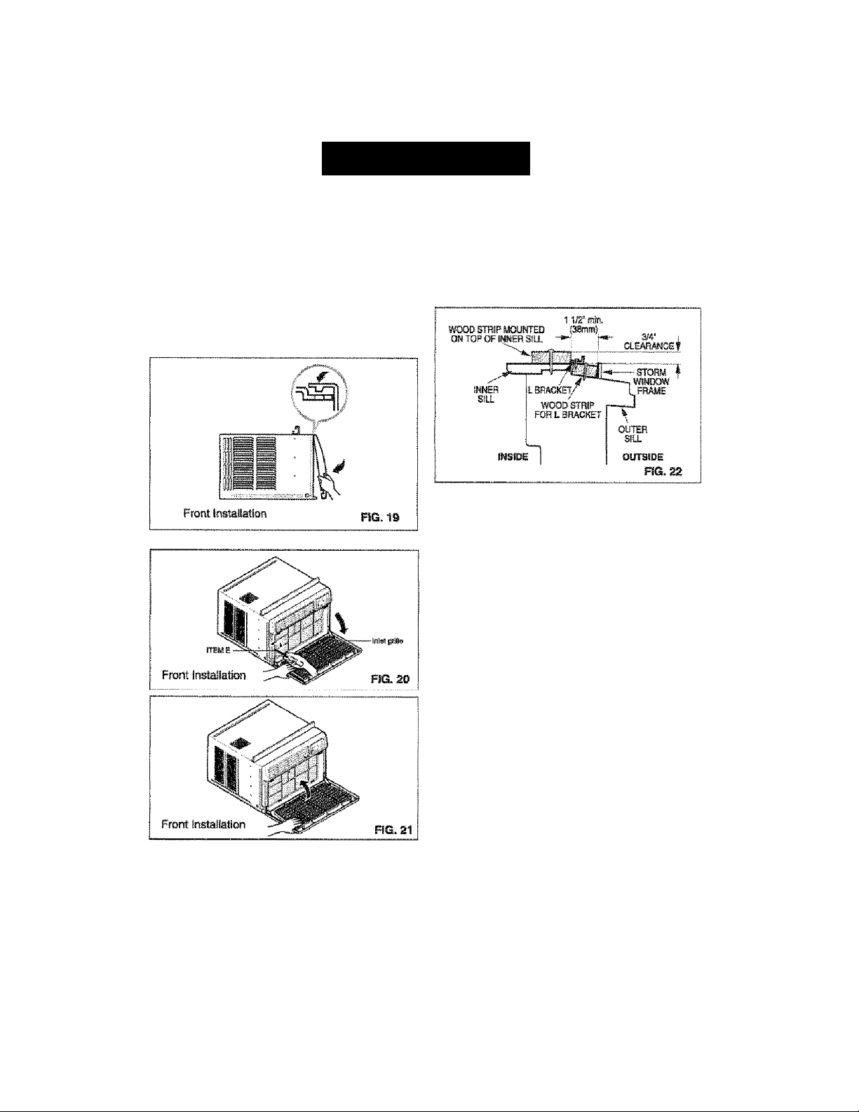
FRONT INSTALLATION
InsM ttie front grills(packed separately) onto the
cabinet as follows;
»Hook upper tabs of front grille into sloK on She
cabmet1op,(FIQ, 19)
»Push front grille's tips towards the cablrret in order
to sn^ side tabs into the cabinet. (F!Q. 19)
* 03«« the talat grille. (FIG. 20)
* install the screw (lTEf\il E) through the front grills.
(FIG. 20)
» Close inlet grille. {FIG. 21}
Top of wood strip should be atproxintately 3/4“
higher than toe storm window frame to help
condsnsatiwi- to drain properly to the outside.
► Install a second wood strip (approximatefy 6' long by
1 Vs* wide and same thickness as first strip) in the
center of the outer sill flush against the back of the
Inner si. Screw the L btactete into this strip.
This wll raise the L bracket m shown in FiG. 22.
REMOVAL FROM WINDOW
• Tum off and unplug the air conditioner.
- Remove f» front pile. See HOW TO REMOVE THE
FRONT GRILLE. Refer to page 13,
• Urtscraw fta side screws that you installed in Step 15.
• Slide toe air amdilionsr out of toe cabinet
BE CAREFUL NOT TO DROP IT. Hold onto it fitmly the
«tools way sliding It out Once femoved, set № safety out
of toe way,
«Remove flie L bracket from window frame and the sash
seat from between fie windows,
»UnsOTW the side curtains from the window frame. Fold
them bffitk to the sWas of toe cabinet
»Remove screws attaching cabinet to Inner sill. Be careful
not to let cabinet fail once scsevis are removed,
• flemovs cabinet fr«n vatidow caning.
• Place arcondlttoner into cEtoinst. Reirtstol! side screws
and Front Grille.
• Place unit and ail assemb^ hatowar® in air conditiorier
shifting caitofl, and store in clean, dry piaoe.
IF AIR COKDraONER iS BLOCKED BY
STORSKI WINDOW FRAME
M stora window presertfe Irsterferertc®, fasten a 2“
wide wood strip to the inner window sill across the full
widfri of the siii. The wood strip *oiJd be Uiiok
enough to raise toe height of the window sill so ttet
the unit can be instailed without interference ftom the
the storm window frame. See FfS. 22,
* Air conditioners cxsversd in this manual pose ®
excessive weight hazard. Two or more people
are nædecf to move and instai the unit.
To prevent injury or strain, use pnc^sr lifting and
carrying techniques when moving unît
» When handling the air cxKidiiioner, be careful to
avcsd cuts frwTt sharp matai fins on front and
rear coils,
» Mate sure alf conditioner does not fall during
removaL
-8-
Page 9
OPERATION
HOW AND WHY
Your room air conditionsr prowdes the following
functions to mate hot wealter living mors
comforteijie;
• Co<^s and circulates raom air.
" Lowers humictiiy by removir® excess moisture.
• Filters out sumnoerttae dwf, dirt, and some
aifbome impurifies.
The air conctWoner perfomis these functtons by
drawing room air torough a filter which traps dust
and dirt parttofes. The air then passes over a
cooling coll which reWgetates the air and removes
excess moisture. The same air is then returned to
tee room- cooler, drier, and cleaner. Molstur©
removed from the room air is carried to the outside
and evaporated.
Your air condfHona" is designed to be easy to
operate and to provide plenty of cooling power.
NORMAL SOUNDS fig.23
Aside from the regularían motor and oomprassor
sounds coming from your air conditioner, you wil'
once in a whit© hear a pinging sound. This is the
result of moisture being picked up from the air tn Ihe
room and thrown against the air conditioner's fan.
This is noima! and should not be cause torconoerri.
Also, do not be alarmed if you hear a slight hissing
or surgiing sound ocming tom your air conditioner
after it is off. These are normal coolant noises.
p Compressor
' The modem high effidency
compressor may have a high
pitched hum or pulsating
noise that cyeles on and off.
- Unit VibraBon
The unit may vibrate
and make noise
because of poor wai!
or window construction.
^ Condenser
You may hear droplete of water hitting
the conctanœr causing a pinging or
cSicking sound.
Fan
You may hear air
movement from
tee fan.
.........
—“
FIQ.2S
CAPACiTY AND RUNNING TIME
Proper unit size is important itt: deciding the desired
comfort for the area you want to cool. The proper
size is determined by the number of square feet
in the area to be cooled, indoor and outdoor
iemperatura and humidity.
Whffliever the heat or humidity load is above normai
Hie air coftdffloner must run longer and more often
to keep tee desired temperature you have selected.
Under heavy heat toad conditions the arroonditionsr
may need to run constantly to keep toe tempsratore
you want.
At times using the MED FAN setting to circulate the
room air may make it comfortable even though the
air is not being cooled. This will decrease your cost
of use.
9-
Page 10
OPERATION
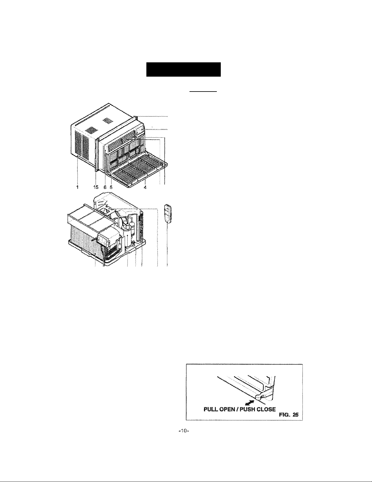
FEATURES
3 2 714
USING THE AIR CONDITIONER
To reduce the risk of fire, sleclrtc
shock, or injury to persons, read the important
SAFETY instajctions secflon before operating this
appliance
To h^in operatlns the air condliloner after
tnstaUatlon, foflow Btase steps:
1. Plug in the air ooncfitioner. (To preverst elecfrical
hamrds-, do not use an extension cord or an
adapter plug.)
2. Set the exhaust vent to tti® CLOSE position.
3. Settle TEMP Control to the coolest setting.
4. Set the MODE control at the highest COOL isvsl.
6. Adjust ihs louvers for comfortaWe air tow.
6. Once the room has ooolad, adjust the TEMP and
Mode Control to the setting you find most
comfortable.
MOTE: If the air conditiotier is turned off, wait 3
minutes hetore restarSng. This allows pressure
inside the compressor to eguaBze. Failure to wait 3
minutes before restarting may cause inefficient
operatton.
If you move the TEMP Control to a warmer, then
Immediately bmvk to a cooler setting, the urrit will
shut off. WaB 3 minutes before restarting,
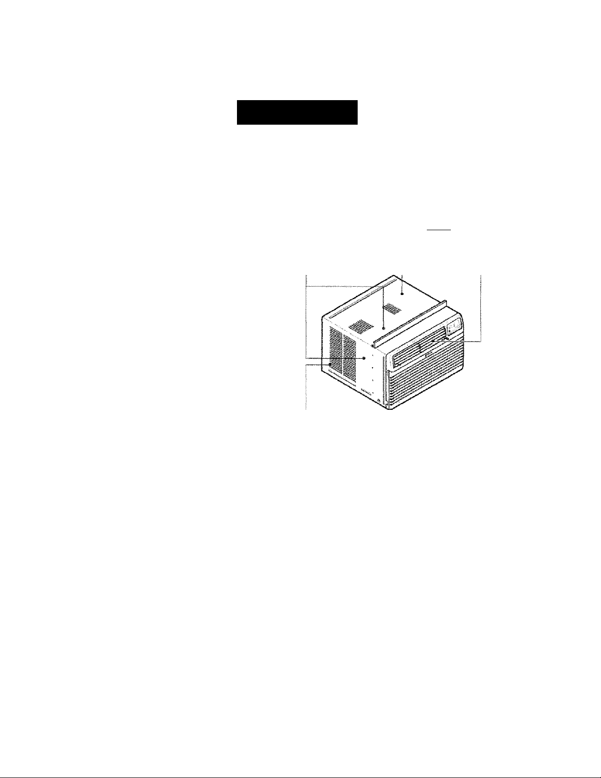
0 6 11 1210 13 16
1. Cabinet
2. Vertical Air
Directiofs Lowers
3. Horizofitei Air
Direction Louvers
4. Wet Griie
5. Air Filter
5. Front Gfiite
7, Ciontrot Panel
8. Power Cord
FÏG. 2S4
9. Evaporator Coit
10. Condenser
11. Compressor
12. Base jjan
13. Brace
14. Upper Guide
15. Curtain
16. Remote Control
VINT CONTROL
The Vent Control allows the air OMiiftioner to
either rsclrcalste inside air (CLOSE) or exhaust
air to the outside (OPEN). (FIG. 25)
• The CLOSE position is used when maximum
cooRng m desired. It may also be used for air
Mcircuiatlon without cooling when toe air
conditioner is sat in the FAN position.
• Irte OPEN position removes state air from the
room and exhausts it to toe outeide. Fresh air is
drawn into the rootn through your home's
normal air passages.
• The OPEN or CLOSE position can be used wHh
any mode selecbon.
Page 11

OPERATION
CONTROL PANEL
- REMOTE CONTROL SIGNAL RECEIVER
flR .
«rsci-Kí
m Ш
Ȥ
tm i
•
'ViC-
......
• TEMPERATURE SETTING
• Use ffiese buttons to automstlcslly control the
temperature of the room. The temperature
cart be set to one of a temperature between
64’Ffo82’F.
»Purii tie TEMP up or down buttorts to shitt
the temperature setting from
82T#^ WF X-TO'F S>»64"F
m
POWER
•To tifin the aircondSonerON, pu#t tftfe button,
TWER
- SHUT-OFF TIME
• You viflll usually use shut-off tíme while you sleep.
»If unit is nirmlng, Use timer ia set mambef of hours until shut-off.
• Every time you push Timer btrtton. h advancss the Timer
seffing as follows: 1 Hour ► 3 Hours 6 Hours>10 Hours
maximuffi.
-START TIME
• If unit te off. Us® tifflsr to set numte of hours before unit starts.
• Every ime you push Tmer btMon, it advances the Tinner setting as tttows: 1 Hour ► 3 Hours ► 6 Hours ^ 10 Hours
fti'SKlmum.
To turn the air conditioner OFF, push
the button again.
•Tliis button tekea priori^ over arty other buttort.
• Wien you first turn it on, the air condionet is on
tre High cool mode and toe Temp, at 70T.
AUTO RESTART
«In the event of a power failure,
the unit will run at the previous.
^ MODE
• Push this button to shift toe mtrde of oparatiorr from COOL-Hl ^ COOL-LOW ► FAN ONLY-HI ^ FAN ONLYLOW.
HORIZONTAL AIR DIRECTION CONTROL
Ths horizontai air direcSon fe adjustsd by moving the vertical
louvers right and left *to yarr ingertfps. (FIG. 2Q
VERTICAL AIR DIRECTION CONTROL
Ths verfisai air direíáían is adjusted by moving Ina horizouM
louvers up and down wlh your fingertips. (FIG. 27)
Page 12

OPERATION
REMOTE CONTROL
NOTE; The Remote Control wi not operate properly if strong ligW shines on the sensor window of ttis Air
Conditioner or if there are obstacles between the Remote Control and the Air Conditioner.
Every time you push button, you wiil hear a beep from the Air Condifioner.
POWER
--------------------------------------—---------------------------—...............
' To tom the air oondionsr ON, push this button. To turn tear cortdloner OFF, риЛ the
button again. This button fakes priority over any other button.
When you first turn It on, the air condiioner is on the High cool mode and the Temp at
70T
TEiiPERATURE SETTING
-----------------------------------------------------------------------------
-
• Use these buttoris to autoffl^tca!^ contro! thè temperature of ttis room.
The temperaiufa can te set w№in a range of 64’F to 82"F.
* Push thè TEMP up or down buttcsis to shift thè temperatops setting from
82T^76“F»-70'Fì*-e4'F
TIMER
- SHUT-OFF TIME
• You wffl usually use shut-off time wife you sleep.
■ If unit is running, Use Timer to set the number of hours until shut-off.
> PiBh Timer buttons to advance the Timer setting as Wlows:
1 Hour{1 Hour-2 Hcwrs)^ 3 Hours(3 Hours-5 Houre)i^ S Hcurs^S Hours-9 HoursJ
10 Hours rnaxlmum.
-START TIME
■ If unit is off, Use tt!8 Timer to set the number of hours before unit sfarts.
■ Push Timer buttons to advars® the Timer setting as follows;
1 Hour^l Hour-2 Hours)>- 3 Hours(3 Hours-B Hours)^6 Hours(6 Hours-S Hours)
P- ID Hours maximum.
MODE
-----------------------------------------------—----------------
• Push ttiis button to ahitt the mode of operatfon from:
COOL-HI ► COOL-LOW ► FAN ONLY-HI ► FAN ONLY-LOW.
POWER^
TEMP
tlMER MOD£
. ; ■: ■ ■ ■.. ■ ..
HOW TO INSERT BATTERIES INTO REMOTE CONTROL
1. Remove the covsr from the back of toe reraois
eontroller.
• Open the cow according to toe arrow direction on toe
cover.
2. Insert two batteries.
" to sure toat fte (+) and (-) directions are correct.
• Be sure toai both battartes ar® rrew.
3. Re-attech the cover.
■ Da TMi use rechargeable batteries.
Such teflerles differ fmm standard dry cete in sh^e,
dimensions, and perfomtanca,
• Rentove toe batteries tram toe remote conlroltsr if toe air
condffloher is not going to bs used for an extsnded
iefiflth of tone.
-12.
Page 13

MAINTENANCE
AIR FILTER CLEANWG
The Air Filter wi beccmie dirty as it removes dust
from ttie insWe atr. It should be washed at least
every 2 weeks. If the Air Filter remains full of dust,
the airflow will decrease ar«J the cooling capacity
will be reduced, pmsibiy damaging the unit.
* Pul! the inlst grtWe forward, grasping both tabs,
then puli out flie air fflter. {FIG, 28}
’■ Wash the Air Filter under the faucet with warm
water. Be sure to shake off af! the water before
replacing the fliter. (FIQ.29)
AIR CONDiTIORER GLEAMING
Clean the frorrt grile and inlet grille by vKlpfng with a
cloth dampened in a mild detergent sOlution.fFlG30)
The cabinet may be washed with mild soap or
detergent and tukewami water, then polished with
liquid appliance wax.
To ensure continued peak efficiency, the crandenser
coils (outdoor side M the unit) should be checked
pertodically and cleaned if they beccroe dc^ed
wito soot or dirt from the atmosphere. Brush or
vacuum exterior coils to remove debris from fins.
HOW TO REMOVE THE FRONT GRILLE
• open the iniet grille, downward.
• Remove the screw securing the Front Grille,
«Push the griile up from the bottom and puli the top
of the grille away from the case to lift the top tabs
outoftieirsiotB.
HOW TO REPLACE THE FRONT GRILLE
Attach the front grille to the cabinet by Ihseifng the
tabs on the grille into the stats on the front of the
cabinet. Push the grille in unBI it snaps into place.
13-
Page 14

TROUBLESHOOTING
BEFORE CALLING FOR SERVICE
Check the following list to be sure a service cal! is really necessary. A quick reference to this manual may
help you avoid an unneeded service t^ll.
THE AIR COMDmONER WILL NOT OPERATE.
Check if... Then...
Wall pi«j cBscoirwcted,
Ноше fuse blown or drcuit breaker tripped,
MCX5É setector is OFT posion.
Uri was turned off arid thai «1 !oo qiidtiy.
TEMP Control set шгтег йтап room tenpetafure.
The current irttermpter device is triped
AIR FROM UNIT DOES NOT FEEL COLD ENOUGH.
Check if... Then...
MODE viator in LOW COOL розШси,
TEMP Orstrol set too warm {lower tiunteh.
Room tomperature below TOT (21 “O).
loc^ №nd^rìtgnìla
THE AIR CONtsmONiB COOLING, 8UT ROOM IS TOO WARM - ICE FORMING ON COOLING COIL BEHIND FROIfT GRILLE
ser^g twbe totKihing evaporasi Шг
Check If... Then...
Ou(di»rtemperature below TO^F (ai^Cj.
Ar filler may be dirty.
TCMP Contrd set too arid fw nlght-Bme ebt^irg.
THEARC^IWIffleCOOUMGLBUTKÎOMISTOOWAWL
Check If...
Ditty air iter -- air restoded.
TEMP CtKiltol set too warm.
Front of ur»t is blociffid by drapes, blinds, funiure.
ate. dstobutfon is resBictaJ,
Ooo®, windc»ys, rajisters, ate. ¡tonn. Cold dr escapes.
Unit reoenBy turned on in hot rooti.
THE AIR CONDITIONER TURNS ON AND OFF RAPIDLY.
Check If... Then...
Out^ temperature is extremely het
NOISi WHEN UNIT IS COOLING.
Check If...
Sound of fin Wtiigweter-from toe ntobture randiS ^Sm,
Window wteto - poor ittetaSlaSon.
WATER DRIPPING INSIDE ROOM WHEN UNIT IS COOUNG.
Check If... Then...
The air cc^citfor^r is gnpropei^ Instsüíed.
WATER DRIPPING OUTSIDE WHEN UNIT IS COOLING.
Check If... Then...
The УГЙ is removing terge epntifes td rnoistiee
from humid room.
Ptidi plus firtiiy into vrall outiat.
Replace fuss with Sme delay type or rsssi drcuit breaker.
Turn MODE ^iKTlor to the dadr®J COCM. seifinq.
Turn urnl pfl and wat3 minutes before resMng,
Turn TEMP Controi dookwise to a coder sdUr^ pgher numbar).
Press the RESET button located on the power cotrf plug
It the RESET isutton will not stay engaged, discontinue use of the air
conditioner and contact a qualified service technician.
Turn sdector to HIGH OOd pesien
Turn TEMP CortrS dadwtee to a cooler settig.
tiooling may rrot occur unSi room Ёгпраайле risæ above 70”F (21 °CJ.
Straigtilen tube away ftom svsçorate «й.
To defrost toe coil, set elector to FAN portion. Then, turn TEMP control
Kwrrietdockimse to a vssmrerseang.
Clean fcr. Rater to Mántenance section of сшиГв marwai To cfetrost,
set selector to FAN posBoi.
To defrost the ссЯ, ^ seledor to a FTW posiSrai. Then, set toe MODE
oantrd at FAN posion or “Ugh Ctrd" wii the ТШР control to a warmer (гоЛзп.
Clean air flltH, Refer to Martienanoe secfai of owner's manual.
tum TEMP cwjiid oiodwrise to a cooler sattlng (higher numtter).
Srarbiockage m frail of unit.
Close doors, windows, iBgisiers, ate.
.Wlow adiiionai ittstorarncr» stored hBStomviBte, celr^, floor, and tumitee.
Set MODE on HIGH ^eed to bring air past coding cols fester.
Then...
This Is normal when tiimridify is high. Close doors, windows, and roisters.
Rater to insfaliadon tosfruidtons or chedc Mto insfeter.
Ti air condMoærsigWly to the outsids to allow water dtanage. Refer to
instafiatlon insfructlons or dieck with Instabr.
TWs is notmaf during ejeessively humid cfejra.
14-
Page 15

INDICE DE MATERIAS
(NDICE DE MATERIAS
GARANTÍA........................................................................ 15
seguridad
..........................................................................
importantes instrucciones de seguridad......................16
REQUERIMIENTOS ELÉCTRICOS
INSTALACIÓN DEL CABLE ELÉCTRICA
INSTALACIÓN
Requerimientos para instaladón
insíallación
Cómo instalarlo—
La eliminación de ia ventana
.......................... .....................
.....................................
............................
......................................
..................................
.......................................
.................
...
.............................. ......ig
.........................
-.---.21
“18
19
OPERACIÓN...............................................22
Cómo y por qué
Sonidos normales.......................................................22
Capacidad y tiempo de funcionamiento •■ ■ 22
...........
............................................ 22
15
16
17
17
18
Características
Uso dei equipo de aire acondicionado ■■ 23
Par?el de control
Control remoto
MANTENIMIENTO.................................................
Limpieza del filtro de! aire
Limpieza del equipo de dre ^ndidonado
Cómo sacar ia repla frontal
Cómo a reemplaza el grílle anterior
CORRECCIÓN DE FALLAS
Antes de Llamar fsira servido
.....................—.................................
......................................................
..........................................................25
.............................
............................
...................
..............................
■■
•■■■
23
24
•26
■26
•26
•26
■26
-■27
—■27
ACUERDOS DE PROTECCIÓN
ESPECIALIZADA....................................
PARA PEDIR SERVICIO
....................
..
Cubierta Trasera
■30
GARANTIA
garantía de un ano por el
EQUIPO DE AIRE ACONDICIONADO DE HABITACIÓN
Durante un año completo a partir de la fecha de
compra, si este equipo de aire acontScionado recibe
rnsuilanimlento y se utiliza para el enfriamiento
normal de habitación según las Instrucciones
Indicadas en este manual del propietario, Sears
reparará gratuitamente este equipo de aire
acondicionado, si tiene algún defecto en materiates
o fabricaciíVi.
GARANTÍA TOTAL DE CINCO AÑOS
POR EL SISTEMA DE REFRIGERACIÓN
HERMÉTICAMENTE SELLADO
Durante cinco años a partir de la fecha de compm,
sí este equipo de aire acondicionado recibe
mantenimiento y se utiliza para e! enfriamiento
normal de habitación según las Irtstrucdones
indicadas en este manual del propietario, Sears
repararé gratuitamente el sistema de refrigeración
hermóticamente seíiado (que consiste en el agente
refrigerante, los tubos de conexión y el compresor},
si tierie aígún defecto en materiales o fabricación.
EL servìgio de GARANTÍA ES
DISPONIBLE CONTACTANDO AL SERVICIO
SEARS AL 1-800-4-MY-HOME®
La protetxton de garantía cubre unicamente a ios
equipos de aire acondicionado usados para uso
domestico y no para uso comercial.
Esta garantía sóio tiene validez mientras ei producto
se esté usando en los Eslados Unidos.
Esta garant afle da derechos legales específicos y
usted puede tener otros derechos que varían de
estado en astado.
Di^buM by S^im, Ftebudc and Co.,
Holiinan «ates, IL 60179
15-
Page 16

SEGURIDAD
IMPORmNTES IMSTRUGCIONÉS DE SEGURIDAD
Las siguientes instrucciones de seguridad le indicarán cómo usar su equipo de aire acondicionado de
habttectón para evitar daños para usted mismo y para su EQUiPO DE AIRE ACONDICIONADO.
ДА01£ШС1А
No almacene ni use gascriina u otros vapores y
líquidos infiam^ies cerca de éste o cualquier otro
eleotrodomósíloo. Lea las etiquetas de los
productos para ver si contienen advertencias sobre
el carácter inflamable de los mismos y otras
advertencias.
ДШЕПШ
Para reducir e! riesgo de incendios, descamas
eléctricas o lesiones personales al usar su equipo
de aire acondicionado, tome las precauciones
básicas, entre las que están las siguientes;
• Asegúrese de que la alimentación eléctrica sea Sa
apropiada para el modelo que usted ha elegido,
• Si el equipo de aire acondicionado debe instalarae
en una ventana, a usted probablemente íe
conviene limpiar primero ambos tactos del vidrio.
Si !a ventena es de) tipo de tres paneles con un
panel incluido de pantalla, le conviene sacar la
ventana completamente antes de la instaíación.
■ Asegúrese de que el equipo de aire
acondicionado na sido instalado correctamente y
con seguridad según se señala en tas
instrucciones separadas de instalación que vienen
en este manual. Conserve este manual y las
instrucciones de instalación para usarlos
posiblemente en el futuro al sacar o volver a
Instalar esta unidad.
• Utilice guantes al manefar si equipo de aire
acondidonado, tenga cuidado para evitar cortadas
con las afiladas aietas metálicas que r ' '
los serpentines frontales y posteriores.
En la placa de serie det fabricante s© irteica cuál ©s
la cafácidad eléctrica ncsninal complete de su nuew
equi^ de aire acwididonado pata nafariffiáón. Consulte
esta ^aca orando vaya a vstificaf tos requerimientos
elécíriojs.
• Asegúrese de que ei equipo de aire acondicionado
úna conexión correcía a tierra. Para reetocir ai
a
es toiportante conectar el equipo correctamente a tierra.
El cordón de alimentadrón eléctrica está eqdpado con
un wKiMe de tres espgas con oxiexión a tetra para
protegerle confta riesgos de descargas efécWcas.
• Su equipo de aire acondkáonado debe mchuterse en
una toma de corriente de p®od que tenga una conejdón
correcta a ttorra. Si ia toma cte contente de pared que
usted piensa usar no está conectada oorro^temente a
tierra o no está protegida con un iusiWe de aoáón
retardada o cm un interruptor de drcuilo, toga que un
electrraste callflcado le ínstate la toma efe comente de
pared en forma correcta.
“ No ponga a tocionar el equífto de aire acondidonado
con una oibiería pratedoia exterior «ictma. Esto podría
ocaácnar dafios mecánicos dentro del dre
acondicionado.
• No use un caUe de extmsión ni un rebute
ad^tedt^.
POR SU SEGURIDAD
JPARA PREVENIR ACCIDENTES
INFORMACIÓN ELECTRICA
o tos riesgos de cfestarn^ elótatioas e incendio,
I hallan en
Evite tes peflgros de incendios y
cteatgas dáctricas. No use un cable de extensión ni un
endiufe adaptador, No elimtos rtnguna de te ^tgas
ifel enchufe del otrcldi de aBmentación elédtica.
Toma de corriente
de pared con
conexión a tierra.
\ _
Repongr
Prueba-
Bajo ninguna circunstoicia corte, quite o evite
ei uso de la conexión a tierra de esta clavija.
IDEAS PARA AHORRAR ENERGÍA
»La capacidad de! equipo de arre actondlcionado
debe corresponder al tamaño de la habitación
para el funcionamiento eficiente y satisfactorio del
equipo.
• Instale e! equipo de aire acondicionado de
habitación en ei lado sombreado de su hogar. Una
ventena orientada hacia e! norte es ia mejor
porque tiene sombra la mayor parte del día.
»No bloquee el aparato de aire acondicionado
toándolo con persianas, cortinas, muebles o en
el exterior con arbustos, recintos u otros edificios.
• Cierre el regulador de tiro de la chimenea, las
rejillas de caiefaectón deí piso y la pared, de tal
modo que el aire frío no se eses^ ni por la
chimenea rrt por los conductos.
' Mattíenga las persianas y las cortinas de otras
vsntenaa cerradas durante ia parte más soleada
dsl día,
• Limpie sí filtro del aire como se rscomlenda en la
sección “MANTENIMIENTO" de este manual.
• a aislamiento correcto y las Juntas herméticas en
puertas y ventanas en su hogar le ayudarán a
mantener el aire caliente afuera y ei aíre frfo
adentro.
• Ai darle sombra externamente a la casa con
ártsoles, plantas o toldos ayudará a reducir la
carga de toabajo del equipó de aire acondidonado.
• Opere los aparatos que producen calor como, por
ejemplo, hornos, lavadoras, secadoras y
lavaplatos durante ia parte más fría del día.
Torminal de
conexión a fierra.
Cable de
alimentación
con clavija
dolada de
conexión a
tierra de 3
terminales.
-16-
Page 17

REQUERIMIENTOS ELÉCTRICOS
RESPETE TOOOS LOS CÓOfÚOS Y
REGLAyENTOS.
BAJO NINGUNA CIRCUNSTANCIA CORTE,
QUITE O EVITE EL USO DE LA CONEXIÓN
A TIERRA DE ESTA CLAVIJA.
ESTE APARATO NECESITA SER
CONECTADO A TIERRA.
Se requiere una alimsníación eléctrica CA,
adecuadamente conectada a tierra con un
fusibfe de 20 A, de 60 Hz y de 250 V,
Se recomisncia un fusible de retando o un
disyuntor de circuito que alimente solamente a
este aparato-
NO USE CABLE ELÉCTRICO DE
EXTENSIÓN.
115V-
NOTA: La forma puede ser difererste según su modelo.
Ufiiice 8i enriiute ds la pared
¡ t 1 \ enchufe tied
\ m / do
V5L/ tSA, 1ESVAC
fsm mm\ óntXiufe de 3
\ Л / Lineas de
ХГ ^ Standard ZSOV,
/ j mm \ enchufe £te 3
l Л y LInsasde
Standard táSV,
Standard 250V,
15A, 250V AC
20A, 25QVAC
Consumo de Energía
Lítíffce un: üisHaJ® da
■tSAMP. oun
Interruptor (fe íSAMP.
Utilice un lusfóie de
ímemjpícíf de 2DAMP-
230V-
o UR
MÉTODO RECOMENDADO DE CONEXIÓN A
TIERRA
Por su propia seguridad este aparato debe
eanectarse a tierra. Este aparato viene
equipado con un cabSe de alimentación y una
clavija de tres terminales. Para reducir al
máximo e( peligro de choque eléctrico, el cable
debe estar conectado a una conexión de pared
con conexión a tierra, y este conexión debe
hacerse de acuerdo con ía úftima edición dei
Código eiéctrico Nadorral {ANSl/NFPA 70). así
como con los códigos y reglamentos íocaies. Si
no existe una conexión de pared adecuada, el
cisente tiene la responsabilidad y la obligación
de mandar instalar, con un eSectricista
calificado, una conexión de pared adecuada de
tres terminales con conexión a tierra.
E! cai» de atimentedón puede Inolulr yn dtepodlivo
intemipior de corrients. La carcasa dal enchúfe cuenta
con uí! batán de prueba y otro de reinido. 0 disposffivo
debe comprobarse periódicamente presionando
prtasro ei botón TEST y despu® RESET.
Si Bf botón TEST no ss descansctó o si ej botón
RESET na t№nnanec6 activo, suspenda el uso del aire
a<»ndio»nato y póngase en contado con un técnto
de servicio caalicsdo.
Peligro de choque eíéoíriOB
Oortecte en una conexión de pared de S tanninates
No quite la temiinaí ds conexión a ttema
No use adaptadores
No use cabte eiéctrico de extensión
Si no ae siguen estas inslruccionss, puede ocasionara
la muerta, un incendio o un choque eléctrico.
INSTALACION
Puede escoger entre ios dos métodos abajo dssraitos de acuerdo a (a forma del taburete da su ventana y su praferenraa.
UTILIZANDO LA RANURA "A"
Apretó sí obturad® isando t ho^s de temió, y т щ el raie
eléctrico 8 través ds la rWiura "A".
CaWsëédnce- '
UTILIZANDO LA RANURA "B“
АргЛ el oÈÉifâdcr usencb el (rayo ¡asuietá) de tomio, y gire
afWífladaTOtJtó рш аш el œWe eléctrico a través cíe ia muta "6*.
-17-
Page 18

INSTALACION
REQUERIMIENTOS PARA
INSTALACION
Su equipo de aire acondicionado ss Irssiaterá en verterías
astáfidar ds dopls panel can anchos «te abertura líbre de
584mm a 914 mm (23a 36 pulgadas). (Figura 1)
SI su equipo de are acondicionado es Insíaiado por la
pared, el tamaño del agujero en la pared tiene que medir
15 S
8/32" X 24 V4'(sin la guía superior).
El marco Irtferlof debe abrirse to suficiente para peimlir
una abertura vertical libre de 361 mm
(15 pulgadas). Las rejillas desviadoras laterales y la parte
posterior dal equipo de aire acondicionado deban tener
un espado libre de aire para permit suflclenle flujo tie
aire a través del condensador para así eliminar ai calor.
La paite posterior ds la unidad debe: quedar al arre libre,
no dentro de un «tifíelo o garaje.
SERVICIO ELECTRICO
i misma que se muestra en la placa dol fabricante de la
unidad (que se halla en si lado derecho del gabinete de
oorriente alterna).
Todos los modelos están equipados cpn un enchufe de
fres espigas para suministrar un servicio correoto y ima:
corjexión a tierra segura y positiva. No cambie el ertohufe
de ninguna forma, no use un enchufe adaptatfor. Si su
toma de corriente de par«f actual no puede usarse wn al
archufe del equipo, llame a un elecírtdsta oaitficado para'
que efectúe las correcciones necesarias.
CONSERVE LA CAJA y este NW^UAL DEL
PROPIETARIO para que le sirva como rsferenoia en el
Wuro. La caja es la mejor manera da conservar la unidad
durante el invierno o cuando no está en uso.
Para evitar el rfesgo de lesiones peiwiales, danos a
su propled«!, o danos al producto debido: a¡ peso de
este equipo y ios flios a que serán expuestos;
• El aire acondiciortado del que se habla en este
tranuai afirma peligro de pe«5 excesivo.
Dos o mas ftersonas se requiere para mover e
instalar la unidad. Para evlter heridas o agotamiento,
use tewttee© ^ropiatías para fevrtar y mover la
unidad.
• Cuidadosamente fospecdone el lugar dcmde el aire
acondicionado sera puesto. Asegúrese que el lugar
sostenga el peso de la unidad sobre un periodo de
tiempo prolongada.
• Martenp su aire aconcficiortado con cuidado. Use
guantes protectores cuando levante o mueva la
tmtttod, EVITE las alelas-fltesas de metei en sf
serpentín delantero y de atras.
• As^urese que el aire acondicionado no se caiga
durarte ¡a instaladmi.
\ SiSf
* •
INSTALACIÓN PIEZAS DE SSONTAJE
F^íra 2
ÍTEM NOMBRE DE U PIEZA CANTIO®
A PANEL DE GUÍA
В SOPORTE DE ANTEPECHO
c
PERNO 2
D
TUERCA 2
E TORNILLO; 25/64“
|m
TORNILLO: 5í8“
iü
TORNÍLLO: 'm"
H
CÌNTA DE ESPUREA -
I CÌNTA DE ESPUMA
J SOPORTE DE CERRADURA
HERRAMIENTAS REQÜER»AS
• Guantes apretados
• Destorntliador normal
• Destornillador PhiHips
• Pinsas
• CudilHo filoso
" Llave inglesa o llave abierta ds 3/8“
» Llave hexagonal de cubo y trinquete de 1/4
de pulgada
• Cinta para medir
•• Taladro eleotrioo
• Broca ds taladro de 1/4“
2
2
13
.
5
1
1
-18-
Page 19

INSTALACION
INSTALACIÓN
Escoja un lugar que le permita llevar si aire Irfo al área
que desea. Las ventanas que se usen para !a
instalación deben tener la resistencia suficfeníe para
soportar el peso del equipo de aíre aGondidonariq. Una
buena instalación con atanotón^ especial a ía correcta
posisión de Sa unidad disminuirá la probabilidad de que
sea necesario efectuar reparaciones.
CuOTdo se desea enWsr más de una habitadón, ia
instaiaoión es muy Importante puesto que si aire frío no
dobla esquinas. Para enfriar sus habitaciones, el aire
trío debe desptezar^ desde ei equipo de ate
acondicionado en una trayectoria recta.
CÓMO INSTALARLO
Gi Saque los tomillos que aseguran eí gabinete
en ambos lados y eti la parte posterior.
da ía repisa de la ventana (o en ia posición deseada
del equipo de aire acondicionado). Coloque
cuidadosamente el gabinete en ia repisa de la ventana
y aliñes la marca central en la parte frontal inferior con
ía línea central marcada en la repisa de la ventana.
agarrando el asa del recipierrte ds 1a base y tirando
de sita hada deferite mientras sostiene el gabinete.
El Corte ta cinta ds espuma (ÍTEM I) a la
extensión apropiada.
Deapegu© el refuerzo y pegúelo en el lado de tfrajo
dei marco de la ventana.
inserte ios paneles de guía (ÍTEM A) en ía gula
superior y las guias de marco del equipo de aíre
acondfcionado. Sujete las cortinas en ía unidad con
tos tomiifos (ÍTEM E).
! Tire del marco interior de la ventana hacia abajo
debás de la gula superior hasta que se encuentre la guía
con e) marco.
MOTA: Mo tíre ds) marco de la ventana tan hada ab^o
que quede feslríngido el movimiento deí panel guía.
, ,í
Monte sin apretar el soporte de antepecho
usando las piezas indicadas en la Figura 9.
-19-
INTEHIOH=^
4m
ÍTEMC
rf======^ E>OTRlOR
\_i_J
■^ÍTEM D
ÍTEMS
Figuras
Page 20

INSTALACION
Ul Ssieccione !a posición m !a que colocará el soporte
ite srtí^eoho cerca üsl punto más externo ©n el
anf^jecho {Figura 10). Fije et soporte de artepedto al
orificio dei carril ds! gabinete er» relación con la posición
aeleMionada usarxio el fflmillo (ÍTEM E).
la postóón ssieccionada efe! antepedio d» ventana.
EIQ El ^¿jinete debe instalarse con una inolinadón muy
ligera (cerca de 1/4 pulgada, 6.35 mm) hada abajo y
hada fuera (Figura 11),
Ajuste el ttóitis y la tuerca dei soporta ds ærtepecha para
equilibrar ©i gabirieta.
ftíílnete rfôfecloîi ОШ1 Í0 posloióft selécdonada usando
el tornio {ÍTEM FHFIgura 12),
Corte te cinta <te espuina para que tenga la longitud
corísete e tnaérteÍB entre e! marco superior ds la ventana
y el marco inferior de la ventana. (Rgum, 14)
Primero, Asegúrese de insertar e! tubo de drenaje en el
fedpísníe de loase arries de la inatotadón. B aparato de
aire acondicionado debe Instalarse cem una ligera
inclinación (1/4“) hada abajo y bacía eí exterior para
poder lograr un drenaje aderaiado de la aoumulaclótí de
agua condensada a través de la tubería ds drensjs.
(ñig. 1S)
■шжрдагЕяш
Оа-ЙЕСИЧВвТЕ
BS BASÉ
й4ЯТЕ1МГ®Я!даСШ,
.wsms.csaABE
Ferais
№ Deslice el cirasis raeíténdoio dentro del gabinete.
(Figuráis)
CUIMDOí Para garantizar la seguridad, vuelva a
ios temites en ios lados dei gabinete.
Cordón de
^Imentadéi
eléctrica
Tornilo
RguralS
Ш\
1
EsSrs cada corSna deS lado complefamants a cada
lado de abrir de ventana. Fíje cada panel gufa
completamente a <sda marco de la ventana usando
tomillos {ÍTEMQ). (Figura !3j
I
Después de volver a instalar la unidad en eí
s, habrá un espacio ite entre la cara inferior de
la unidad y el artepecho de la ventana. Use ía cinta tfe
esprta (ШМ H) provista pata cubrtr esta abertura.
decorativo. Arstes de usar la caracterfeíJea de ventílación.
Page 21

INSTALACION
ü IMSmLftCÍÓN FfíONTAL
instale la rejilla frontat can ei gabinete de la
siguiente manera:
• Tíre de te rejilla frontal hacia debajo desde la parte
superior de! gabinete
Empuje las puntas de la rejilla frontal hada el
gabinete para insertar las lengüetas de la rejilla
dentro tisi gabinste.
• Abra la rejilla de entrada
• Apriete ei tomillo (ÍTEM Ej a través de te rejilla
frontal fijándolo al recipiente de base
• Cierre la raliila de entrada
li i'
INSTALACIÓN FRONTAL
INSTALACIÓN FRONTAL
INSTALACIÓN FRONTAL
IS Si EL ACÓNOICIONADOrt OE Al№ ESTA
BLOQUEADO POñ EL MARCO DE U CONTRAVENTANA
• Si la contraventana interfiere, fije un listón de madera de
2” de ffltcho al alféizar interior de la ventana, que
atfavie^ la anchura total del alféizar. El listen de
madera debe ser suficierslemeníe grueso para levantar
te altura del atfslzar de la ventana de tal manera que la
untóad pueda ser inhalada sin la Waríerancía del marco
Figuráis
.................
Figura 21
LA ELMNACION DE U VENTANA
• Apague el acatidloíonador aéreo.
• Qurie al grille anterior. Vea COMO A REEMPLASt EL SRSLU
• Destemie ei torrtlü del lado que usted Instaló sn ^ Paso 15.
• Oesite el acondraonador aéreo fuera de! gabinete. TENGA
• Quite si paréntesis L dá «што ¡te ventana y el seto de banda
' Dastemilte las »ttinas del (ads del marro ds ventana.
:
«Quite ei tornillo ronsoíar дшг1пЛ ai аМа! toterior. Tenga cuidado
• Quits gabiftete de abrir de ventana.
»Coloque aamefciofíador aéreo en si дй>Ме. Vuelva e
«Gaioqus te imídad y toda fetretería ife la asesmbl® en el
de la cofítraventana. Vea la Figura 22.
La parte superior del lislón de madera debe ser
aproMmadamente ^4* más alto que e1 marco de ía
Dontiavantana □ st listótt de madera (tora de la casa)
para que el ущюг emanado de la unidad pueda drenar
adecuadaraante hacia el exterior.
> Instale un segundo listón de madera (tfe aproximadamente
6' de largo y T de antíio y del msmo grosor dei primer
feto) en el cerfro del alféizar awerior nivelado con la
pfflie posterior del alféizar interior. Atomílie tós soportes L
entre la faja. Esto tevanlaré el shorts L como se muestra
eniaFgufa22-
1 1/2* raiEi.
раДШАВЕЮШЕВА
MONTMiA SOBRE'
LAPAíreSUPEflK*.
DEL DESCANSO r—
INTEfllOR
ANTEPECHO
мтегаон
ANTERIOR. Reflérasa a página2e.
CUIDADO no A la GOTA Теща en to firmemente la manera
entera que desliza lueta. Una vez quitado, ic puso seguridad
fuera da te таяеш.
de entra el windows.
Dóblalos apoyan a fas lados del gabinete.
no a psrmió que pWnete falte даа vez tomllos se quito.
instalar bs tornaíos dsl lado y Grite Menor,
raitdn aéreo del envte dsl acondloíonador, y en la tienda en
limpia, saca si lugar,
TÉRADEMADEñA
fSSnim)
аир|=едт
EN L /
RARA lA MENSULA
i VMENSUUDE
ANTEPECHO
10Я I
PSSlRA^ON t
VBITANADE i
HOJA DOBLE ^
АЫ1ВРВЖ
EXT&mn
F^ura2S
A CUtDADO
• il aire acowfldonado del que se habla en este
manual afirma peligro da peso excesiva.
Dos o mas personas se requtere para mover e
irtstala’ la unidad. Para miar heridas o
agotomlento, usa tecntcas apropiadas para
tevntar y mover ia unidad,
• Al martejar ia unidad, tenga cuidado para evitar
cortarse ron las Éerto metálicas afiladas que
están en (os serpenfines trorrtet y posterior.
• Asegurase que él aire acondítíonado no se caiga
durante la inscción.
■21 -
Page 22

OPERACION
CÓMO Y POR QUÉ
Su equipo de aíre acondicionado de ^laíзtecl6n
brinda las siguientes funcionas para hacer que la
vida en climas cáiidos sea más confortahte:
• Enfría y hace circular ei aire por la habitación
« Disminuye la humedad eliminando la humedad
excesiva.
» Filtra et polvo, el sudo y algunas impurezas
transportadas sn el aire del clima veraniego.
ES equipo de aire acondicionado realiza estas
fundones hadando pasar el aire dai medio
ambiente a tevés de un filtro que atrapa ías
paiticulas de polvo y sucio. El aire pasa entonces
por un serpentín de enfriamiento que refrigera ef
aire y eíimina ei exceso de humedad E! mismo aíre
regresa entonces a! enfriador, secador y limpiador
del aire del ambiente. La humedad extelda del aire
ambiente as llevada al exterior y evaporada.
Su aire acondicionado está diseñado para operar y
suministrar una enorme potencia de enfriamiento.
SONIDOS NORMALES Figura 23
Además de los sonidos regulares dei motor érf
ventilador y el compresor que salen de su equipo
de aire acondtóortado, usted escuchará de vez en
cuando un sonido mstálico. Este sonido es
producido por la humedad qu® as recogida ctel aire
en el ambiente y es lanzada, contra el ventilador del
equipo de aire acondicionado. Esto es algo normal
que no debe ser motivo de preocupación, De igual
modo, fso se alarme si usted escucha un ligero
sonido de silbido o borboteo prownieníe de su
equipo de aíre acondidQnadD después qu® lo
apaga. Estos son ruidos normales dei refrigerante.
CAPACIDAD Y TIEMPO DE
FUNCIONAMIENTO
M
d«*Sr cuál dete ser la comodidad tíSMida para el Ésa que
usted quiere silriav, es Inparíanisctelffimíriaf
de la imitiad. Una tmldai pequeña no tenia fe capaddad para
enftfer, йфпйо te. ares calurosa, В temario tóecuado es
deíaranado por eí ntaro de metes malrados que lene si
éraa que se desea aiftiar, así como por la temperatura irtíeÉjr
exterior y por la htmected. Una unidad demasMo grande á
ertrla, pfflo ro tirahumetista, dejafKlo la
■SiefitefS ípe la сада térmica de! vsnffarfer este por moma de
bnortral, el equipo de aire aconditíonado debe irrrdorsar más
tiempo para marítener iate^eraftrra deseada tpe uáed ha
selecdQiiado. йр ¡míloionas te ипаоагрйяпЫ muy
pésate, puede ser necesatfo qu® ei equipo te aíra
acondictanate tentíone oinstertanwfile para rraiteiw la
tenpaatura deseada.
d tam mo
im
fria y húmeda.
соггайо
En ooasiorí^, tí uso de №D FAN ¡rara hacer drcuiar el aire po
te tabteciéff hace que ei arrbíirrts sea rafe rxrtfatóíle aun
cuetes el r» esté etiWarxiO' el aire. №nBas rnás tiempo
y con raaycr frectienda totee el equipo ds fee
acotxlÍBBnada, más eledrfeíted csmsutwá y mayores ssife kss
coSosdeaiuSD.
- Comprasor
El moderno compresor de gran
eficterKiia puede produte un ruido
agudo de mufíTiuito o un ruido de
pulsatíén que viene y se vs.
-Vlbraelones de l8
unidad
La unidad puede vibrar y
hacer ruido debido a la
defldente construcción
Veialfador
Usted puede
escuchar ef
movimianto del
aire proveniertis
del veniadcr
------
Conder^acior
Usted puede esjuchar gotas de agua que caen
sobre ei condensador causando un soñido
metálico o un sonido de chasquido.
Rgura23
y
‘22-
Page 23

OPERACIÓN
CAHACTEeiSTICAS
9 8 11 1212 13 16
1. Gsájineíe
2. Deflector vertical
deaíre
3. Deflector horizorttai
de aire
4. Toma de aire
5. FWfo del aire
6. Parrilla frontal
7. TatbtoK) de conto!
8. Cordón de
alímentactón
eléctiica
Figura. 24
9. Evaporador
10. Condensador
11. Compresor
12. Recipiente de base
13. Puntal
14. Gola superior
15. Cortina
16. Control remoto
USO DEL EQUIPO DE AIRE
ACONDICIONADO
descargas elóctrica o lesiones peraonates, tea las
fypORTANTES ÍNSTRUCCiONES DE
SEGURIDAD antes de operar esl® aparato.
Para corrtertzar a ytiiw at ««¡ulpo da ai№
acondicionado, siga estos pasos:
1. Enchufe ®I equipo de aire acondicionado. (Para
prevenir riesgos de descargas aiéctricas, no uss
un cable de extensión ni un enchufe adaptador.)
2. Ajuste el extractor de aire en la posidórt CLOSE
3. Ajuste el control de MODE si mas alto nivel
fresco. ■
4. Ajuste el control del ventilador al más ate nivel.
5. Ajuste las rejillas desviadoras para lograr un flujo
confortóte de aire.
6. Una vez que !a habitación se haya enfriado,
afuste el control de temperatura TEMP a. la
graduación que usted considere más confortable.
NOTA: Si se apaga el aíre acondicionado, espere 3
minutos antes de volver a encenderlo. Esto permite
que se estabilice la presión dentro del compresor, ,
Si no sigue estas instrucciones, el equipo podría .
f uncteriar con poca ef iciancía.
St usted mueve el TEMP el control a un warmer,
entonces inmedialamerjte espalda U UíliB colocación:
más fresca, !a unidad apagará. Espere 3 miniitos.
CONTROL DE VENTILACIÓN
El conird de №níilación permite qi» el equipo de ame
acondáonacto haga recircular el aire en el interior de la
habitaran (CLOSE) o saque al aire htoia el escterior
(OPEN), (Figura 25|
• la posid&t CLOSE síiw cuando se desea un
enimmientó máximo. Tafnbién puede usares pata
tiK»r redícutffi- e! aire sin enfriar la habitación cuando
el equipo de aíre acondiciotrado se ^usta en la
posU&iFW.
• La j^idón OPEN exdae el ate esíancaaío de la
tabitación y lo expulsa hacia fuera. El aire fresco es
Bevado tacia si interior de la habitación a través de
los pasajes nortrates de alts que se hallati en tos
hogares.
• La posidórt OPEN O CLOSE puéde usarse con
cualquier selecckfri de ventilador.
I Para reducir et riesgo ds íncerrdia,
•
Page 24

PANEL DE CONTROL
OPERACION
•RECEPTOR DE SEÑAL
r AJUSTE DE LA TEMPERATURA
• Utilice asios botones para controlar
antomátíoamente la temperatura de ia ftabttacife.
La temperatura puede ajustarse en un rango de
e4“Fae2=F.
• pyise los botones TÊMP arriba o abajo pata
cambiar el ajuste de tempeatura errtre 82“F ►
7r’F*^7rF^64”F,
ENECNDIDO/APAGADO
• Pera ENCENDER e! sistema presione el botón,
y para APAGARLO presiofie e! botón otra vez,
• Este ¡botón tterte prioridad sobre todos ios otros
botones.
'MARCADOR DE ENCENWDO/APAGADO
“ OPERACIÓN DE PARADA:
" Noimaimente irtilizató la hora de pagado misnfras duerna.
• Cuando la unidad esté ersoendida, tifies Tmer p»a ajustar
ei número de. horas franscorridas las cuales la unidad se apagará,
• Cada vez gue pulsa el botón Timer, eí ajuste Timer avanza dsl
siguiente modoil Hora► 3 Horas»»6 Horas ¡►I0 Horas máximo.
'OPERACIÓN DE IMCIACIÓN;
• Cuando la unidad esté apagada, utiiee Timer para ajustar e! nüras'o de horas transcarridas las cy^es ía unidad se
ersenderá.
• Cada V6Z que pulsa el botín Timer, el ajuSe Timer avanza del siguiente modo: 1 Hora 3 Horas ► 6 Horas i»-10 Horas
máximo
•Cuartdo Ud, lo sndencíe por primera vez, el
sistema está el y la íerapsratóra es de 70“F.
REÎNICIO AUTOMÁTICO.
»Si se produce un corte de energía, la
tiredadí funcionara con tos ajustes previos.
■MODE
• Pulse este botón para camWar ei modo de fundonamiento entre COOL-HÍ ^ COOL-LOW► FAN ONLY-Hf
► FAN ONLY-LOW.
CONTROL DE LA- DIRECCIÓN
La. dirección horizontal del aire es ajustada rolando
ia planea verdcal batía la derecha a hacia ta
izquierda. (Fígura.28)
CONTROL DE DiRECCIÍ N VERTICAL DEL AIRE
La direcfitón vertical del mm se ajusta moviendo la
rejilla honzonfal hada delante o hacia atrás.
(F«ura. 27)
■24 -
Page 25

OPERACION
CONTROL REMOTO
Precsuciófc El tfisposStiovo de contra! remoto no ftmcíonará adecuadamente sí la ventana sensora del
acondicionador de aire es expuesta a luz fuerte, o si hay obstáculos entre el dispositivo de control remoto y
el acondicionador de aire. Cuando opere el aire acondidonado con el control remoto, deberá otr un pito.
ENECNDÍOO/APAGADO
' Para ENCENDER el sistema presione el botón, y para APACARLO presione
el botón otra vez,
Este botón ííerte prioridad sobre todos los otros botones.
Cuando Ud, lo endertde por primera vez, el sistema está en ef y la
temperatura es de 70T,
.......
....................................
......
AJUSTE DE LA TEMPERATURA -—---------------------------------
• Utilice estos botones para controlar atitomáticameote la temperatura de la
h^iíación. La terr^eratura puede gustarse en un rango de 64°Fa 82T.
• Pulse los botones TEyp arriba o abajo para cambiar el ajuste de íemperatuTa
entre 82T»“ 76“F 64“F.
MARCADOR DE ENCENWDO/APAeAÍXÍ------------------------------------------
-OPERACIÓN DE PARADA;
• Normtímsnte ufiilzará la hora de apeado mientras duernta.
• Cuando la unidad esto encardlda, utilice Timar para ajustar el número de horas
tnanscuriidas las cuales la. unidad se apagará.
• Pulse tos botones Timar para avanzar el ajuste Timer daf slgufeníe modo; 1 Hora (1
Hofa*2 Horas) )»• 3 Horas(3 Horas-5 Horas) 6 Horas (6 Horas-9 Horas) 10 Horas
méximo,
- OPERACIÓN DE INICIACIÓN;
• Cuando la unidad esté pagada, utilice Timer para ajustar el número de tioras
transcutridas fes cuates la unidad ss sncenderá.
• Pulse los botones Timer para avanzar et ajuste Timar del siguiente modo; 1 Hora(1
Hora-2 Horas) 3 Horas<3 Horas-8 Horas) ^ S Horas (6 Hsfas-9 Horas) ► W Horas
trtfedmo.
MODE ...................................................................................................
• Puíse este botón para cambiar el modo de tórscionamierto entre COOL-W ► COOL-
LOW ► FAN ONLY-HI ► FAN ONLY-LOW.
......
COMO A BATERIAS DE ADICION
1. Quite ia cubierta ds la espalda del difecfor remoto.
•Abra la cubierta según ia dirección de la flecha.
2. Meta a baíerias.
• Esté seguro pus el {^-) y (-) las direcciones son
trarreotos. ^
«Esté seguro que ambas baterías son nuevas,
a Re-coneote la cubierta.
EN EL CONTROL REMOTO
♦ No uflHce batería recargables, éstas son diferentes de
forma, de dimensión y uso respecto a las baterías
secas usuales.
• Seque las baterías del tatemando cuando el
acondtcteríaclor no vaya a ser usado durante un largo
período,
-25-
Page 26

LimPlEZA DEL FILTRO DEL AIRE
El filtro del aire se irà ensuciando a medida que va
atrapando el pdvo proveniente del aire tortor. £s
preciso lavar al filtro del aire al menos cada dos
semanas. Si si filtro del aire permanece lleno de polvo, el
flujo de aire disminuirá y se reducirá la oapaádad de
enfrtamianlo del equipo, con posWes dafios para la
unidad. (Pigura 28)
• Tire de la rejilla de srirada hacia delante aprrancío
ambas lengüetas y tira del filtra del arre hasta sacarlo.
*Lave el filtro del aire en agua tibia a. Asegúrese de
eliminar ¡otfe el agua saraidiendo el filtro antes de volver
a ponsfio en ai posicifin. (Figura 2S)
CÓMO SACAR LA REJILLA FRONTAL
•Saipe ei toratlo que mantiene ia replia frontal en poaraón.
‘Quite el torrsilto que asegura (e reja delantera,
• Empuje ia rapa hacia arriba de abajo y jale la f
LIMPIEZA DEL EQUIPO DE AIRE
ACONDICIONADO
La rejilla frotitaí y la tejía d® entrada del aire puedan lavarse
con un pafío humededdo en una saluclór? de detsrpnte
suave,(Rg«rg3í!) El gabirtete puede lavarse con m jítói o
detergente suave y agua libia, seguidamente puede pulirás
con cera líquida espacial para eIsctmítemésttecB,
Para aseprar una eficiencia máxima coníimia. ios
serpentines del condensador (lado de enfrente de la unidadi
cfeben rewsarse periódtomente y limpiarse sí están
obstHitdos OTJ holitf! s con sucio de la atmósfera.
COMO A REEMPLAZA EL
GRILLE ANTERIOR
Pegue el panel frontsi a la caja ínsertendo ios fijadores
en el pans! adentro tos del panel de la caja.
affiba de la rejilla lejos de la base para tevantar Ies
lengüetas de artiba hacia ahfsra de las ranuras.
№pa de en^'aäs.
Repía
Figura 31
Figura 80
■2S-
Page 27

CORRECCION DE FALLAS
ANTES DE LLAMAR PARA SERVICIO
Oteque la siguiente lista para asegurarse si en realidad es rrecesario llamar para servido. Una referencia tapida a
este manual puede evitar una llamada para servicio innecesaria.
EL EQUIPO DE AIRE ACOMOICIONÍADO MO FUNCIONA.
B «lotwfe no «iá ocnectado «1 la toma de ooiifent« ¡te paredConecte á «ichitfe tinnemeite en ia isim de ctrtente de paied.
0 0 ¿ WBíti^ de dnatto se te átpaiad^
B seÍBCtor ctel venílador MODE en la pos¡d6n da OFF.
U unidad se iftagó y se voMé 3 srtcmder ttaaslado )á|Ma.
El oortd da terqoetaiura TEWP se 4¡si6 más oálido pue b
tenpeiaSiiaamdientB.
El d^»s№vo №m^r de o^nte ssb desowtededo.
EL AIRE DE LA UNIDAD NO SALE BASTANTE FRÍO.
0 ssiedor a una oo^'én más LOW CX30L
B oatal de tanTOiatuaTaf“ se aiu^ demaáado oSitío írsírerD rrasbaiol.
La íempetaima arttente está por (tóiajo de tes 70“ F {21'C)
B tubo serm' de tenperatuia está tocando el serpentín evaporador
que está sSuado detrás del H№o del aite.
ЕЖДСШШтЮЕ1ПУ^РЕ1ЮиНШАа0Н5Е8ШЕ[Ет£Ш(ЙШ^^т1АШ£У11БЕ№тОЁт1АЙ1В1ГО
raHÁSOe-PANELDECmAnVO ШШМ.
LaíHip6Btuiaaniid6i*6nelaÉ5Mre^porttó^deto$TO“F(2re),
B ft№t> del aire puede estar suciú.
i control de twppwatum se «|uaió dwtasBdo frío p»a el enfifamiento
rHXrftuniQ.
Iteróte ef con un a:(^n 0 resísta SÍ
fctteiTU|)tót dnxii3Por^ el sáe¡±5rat laposidór dsCOOL,
Apague la mtíaayesperesittlfwtttgfflttes de ¥BíveraencS(feíla,
Gire ¿ Ot^lnoí do m si sedado ias dol hasta una
gr^uacjón (nuniBíts fnas alio).
PtssÉone á bofti RE^ átuado en el enctafe dai caMe ds alira«cián
9 el bcMi RESET no peimtece actwe, su^enda á use dá alte acoiidii3ot«do
y póngMe en oanads con uti técnico de sewteia cuattafte.
Gire sí selector a ima posidón HIGH СОТGite si co№á de tempeiaíj ta en ai serate delssaquissdetráttjpara
Mo puede prodiriise et епМага1Ш1Ь que la temperatura arnbletáe sttea
рогагкяяш de tos 70° F {21°Ci,
Endffisce ^ tubo aie|ánítelo del s^pentín еюрогжЬг.
Para daseempelar é seipersiín lleve el setet» a le posictort FAN.
S^kiametA, el cwitrol de tempaiáuffi TB^P wt á senf do de És spbs
del reloj pata tetarlo basta una giaduanten más cáWs.
iSpe ai ira. CorisiteSeatKiórí “Wantaínírtcf, Pa« demngSr, tete el
sstecbM'3 le pcñtiór) FAN.
Para desísít^laf el sstpenlin, «ata el stoSot a la posiotón FAM.
S^demeiite afuste el ccrAol de tempwatura a una posición rrbs cÉída,
аЖАС0гаС1ЩШ)1Нт№,Ртит[ГД{^1!8Е31ШТЕ0ЕМШР0США;№ЕГОМАШЕ0Е^Е11ЁГт1№Ш
EMFRIAiaíTO шт DB. PANEL DECOBAWO FRONTAL,
0 itfo dd aire está sudo ctm lo que se te^npe ^ ilu|o dd aire.
Bcontrol detenpei^uaTE№ se grxiuáen posicimdemas^cÉtía,
La parte frorel'dé i ti'ñídátl eaá bloqueaík por corfiras, persiariás,
etc. que restrinoen ladi^bud^del aire.
pu»fás, ventanas, r^№as de calte;№t, Urétera, están i№tas con
Id que se permite é escapa de! aite frío.
La unidad acabe de enoanderse en una bebitedóri caerte.
EL EQUIPO DE AIRE ACONDICIONADO SE APAGA Y SE ENCIENDE RÁPIDAMENTE.
U te^statura es extiemE^bmet^ caSwte. ^uste al MOiX) m la velocidad ALTA para hacer que «1 abe por la báwia
SE ESCUCHAN RUIDOS CUANDO LA UNIDAD ESTÁ ENFRIANDO.
B sonido d^ vattìador al dVKW owrtta agua tíd átona (fe
BlimiMn ds hutnetted.
Viiraaán ds lavetáana; Intoecién deficiente.
EL AGUA GOTEA DENTRO DE LA HABITACIÓM CUANDO LA UNIDAD ESTÁ ENFRIANDO.
Ins^sdén Indine 1де!шш1в É ада dsaiis aooTKtjonada haetefa píte extertiífmpemSrd
EL AGUA GOTEA AFUERA CUANDO LA UNIDAD ESTÁ ENFRIANDO.
La unidad está etdi^atoo grandes canádades de bmedad de una
habteiónhLRiKk
linpia á lito dei alíB. CatsuHe la sección ‘Martetmiento'.
Gke el Cün№a№ternpsi8№ № e) senSde de 1^ tíet ratei para llevatte a
una praduadón irás Ms. (Námsio más alto)
Bmns el Ысризо алМе de ia unidad.
Qene las puaías, vwtanas, tepes de cafefaeaón, etefiera.
Pernia qi» ttañscSiii ш poco más de lietnpo para dminar d ^or ateceratáf
en íéb paredes, á tede, sí ршу fas imtebles.
ds r^lgeraíd^ rápido.
Este es narnai a»dü ia hurnedad № alta. Сите te puerW, tolta« y гЯю
de calefacción.
Lea las irtslrutqon« de it^aclón o consute á instelador.
Лшф dd адж Ijea a» я8!шояж® da wiefedén o oonaAe ai ínaaíiSar.
Este Ю algo тгпй áirante Its días «¡oasivatiente tómectes.
-27-
Page 28

■28-
Page 29

мУ
о>
C4J
Page 30

Master Protection Agreements
Congratulations on making a smart purchase.
Your new Kenmore® product is designed and
manufactured for years of dependable operation.
But like ail prcjducts, it may require preventive
maintenance or repairfrom lime to time,
That's when having a Master Protection Agreement
can save you money and aggravation.
Purchase a Maser Protection Agreement now and
protect yourself from unergiected hassle and
expense.
The Master Protection Agreement also helps extend
the life of your new product. Here's what's included
in the Agreement;
0' Expert service by our 12,000 professlonai
repair specialists
^ Unlimited service end no charge for parts and
labor on ail covered repairs
^ “No-temon" guarantee - rspiacement of your
covered product if four or mors product feilures
occur within twelve months
g' Product replacement if your covered product
^ can't be fixed
^ Annual Preventive ülialntenance Check at your
request - no extra charge
[0 Fast help by phone - phone support from a
Sears tediniclar» on products requiring iivhome
repair, plus convenient repair scheduling
O' Power surge protection against eiectrica!
^ damage due to power fluduatlorrs
^ Rental reimbursement if repair of your covered
product takes longer than promised
Once you purchase the Agreement, a simple phone
call is all that It takes for you to schedule service.
You can call anytime day or night, or scheduie a
service appointment online.
Sears has over 12,000 professional repair
speciailsts, who have access to over 4.5 miiiion
quality parts and accessories. That's the kind of
professionalism you can count on to help prolong
the life of your new purchase for years to come.
Purchase your Master Protection Agreement todayl
Some limitations and exclusions apply.
For prices and additional information cali
1-80Q-827-66SS.
Sears installation Service
For Sears professional Installation of home
appliances, garage door openers, water
heaters, and other major home items, in the
U.S.A. call 1-800-4-MY-HOME®
Acuerdos de Protección Especializada
¡Enhambuenal Ha realizado una orxnpra inteligente.
Su nuevo aparato Kenmore® está diseñado y fabricado
para ofrecerte efios de buen funcionamiento.
Sin embaigo, ai igual que todos ios productos, puede
precisar un mantenirniento preventivo o incluso alguna
reparadén de vez en cuando. En esas ocasiones, un
Master Protectiorr í^reement puede ayudarte a ahorrar
dinero e inconvenientes.
Adquiera un Maser Protection Agreement ahora, y
protéjase a sf mismo de molestias y gastos inesperados.
Et Master Protection Agreement le ayudará también a
prolongar ia vida de su nuevo aparato. Los siguientes
servidos están incJuidos:
^ Servicio experto por parte de cualquiera de
nuestros 12.000 técnicos profesionales especialistas
de Sears.
^ Prestación de aervieíos sin íimitaciones y sin
cargarle las piezas o la mano de obra en todas las
reparecbnes cubiertas pcx el acuerdo.
^ Garantía seria de sustKucfón de ¡as piezas dei
producto cubierto por el acuerdo, sf cuatro o más
piezas se mostrasen defectuosas en un periodo de
doce meses.
^ Sustitución de! producto por otro nuevo, si ei
defectuoso no pudiese repararse.
^ Control da mantenimiento anual preventivo,
siwrtpre que lo desee y sin gasto adicional alguno.
Asistencia telefónica inmediata de un técnico
espeiáaiista en productos que han de ser reparados a
domitílio, además de una programación adecuada de
la reparación,
^ PrateceJón contra subidas de tensión que
provoquen daños eSéctricos debidos a las
fiuctiiadones en et sumirtlstro.
^ Beinbagro del alqutier si la operación del producto
^ ¡leva más tiempo de! prorntetido
Una vez que haya adquirido el Agreement, no necesitará
más que una símpia Bamada para solicitar el servido de
su aparato. Además, podrá hacerío en cualquier momenío
def día o de ia nodie, o solcítar una cita para prestación
de servidos onííne.
Sears cuenta con más de 12.000 técnicos profesonaies
especialistas en reparadones, con acceso a de 4,5
miilones de piezas de sustitución y accesorios de caSdad,
Éste será el tipo de profesionaídad y servicio con ei que
podrá contar para prolongar la vida de su nuevo producto
por muchos años. iAdqulera hoy mismo su Master
Protactirxi Agreement!
Se aplicarán algunas limitaciones y
restricciones.
Si desea hacer alguna consulta sobre ios
precios u otra Infmnacién adiclonat, te rogamos
llame a¡ teléfono 1-S00^27-665S.
Servicios de lostalaclórt Sears
Para solicitar servicios de ínslalaaón profesionales
de Sears de eíectrodomésticos, mandos de apertera
de puertas de garajes, calentadores de agua y otros
aparatos en ios Estados Unidos, puede llamar a
1-8QO-4-MY-HOME®
-30-
Page 31

Page 32

Get it fixed, at your ИЩ| dr ours!
Your Horn®
For repair - In your home-of all major brand appliances,
lawn and garden equipment, or heating and cooling systems,
nO' matter who made St, no matter who sold Itt
For the replacement parts, accessories and
owner's manuals that you need to do-it-yourself.
For Sears professional instaliation of home appliances
and Items like garage door openers and water heaters,
t-800-4-M¥-HOS^E®
Call anytime, day or night (U.S.A. and Canada)
www.sears.eoin www.$ears.ca
Our Home
For repair of carry-in items like vacuums, lawn equipment,
and electronics, call or go on-line for the location of your nearest
Sears Parts it Repair Center.
1-800-488-1222
Call anytime, day or night (U.S A only)
To purchase a protection agreement{U.S.A.)
or maintenance agreement(Canada) on a product serviced by Sears:
1 -800-827-6655 (U.S.A.) 1 “800*361-6665 (Canada)
Para pedir servicio de reparación
a domiciüo, y para ordenar piezas:
1-888-SU-HOGAR"“
(1-888-784-6427)
® Registered Trademerit / ™ TradeniiHiiî / Swv«« Sears, Rtjebuoft smS Co.
® Marra Registrada / ™ Marra de Pâtoisa /“ Haras de Setviaia de Sears, ftûabuok. arid Co,
“ Marque de cammetcs 1 “ Marque déposée de Sears, Ro^udt arsd Co.
Au Canada pour service en français:
1-800-LE-FOYER“^
(1-SOO-S33-693?)
www.sears.ca
© Seats Brands, U,C
Part No.: 3828A21007J
 Loading...