

Page 1
Owner's Manual
Manual del Propietario
KenmorG
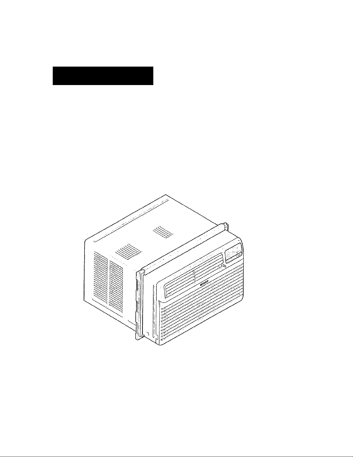
ROOM AIR CONDITIONER
ACONDICIONADOR DE AIRE DE VENTANA
Model, Modelo 580. 72089
Sears, Roebuck and Co., Hoffman Estates, IL 60179 Ü.S.A.
www.sears.com
Page 2

TABLE OF CONTENTS
TABLE OF CONTENTS..................
WARRANTY——
SAFETY
Important Safety instructions
.......................................................
.........-.................................
------------
-
ELECTRICAL REQUIREMENTS
INSTALLING THE POWER CORD
INSTALLATION
Installation Requirements-
Installation.........—......
How to Install
Removal from Window-
OPERATION
How and Why .........
Normal Sounds
Capacity and Running Time-
.......
..............
...........
...........
.... ........
...........
-
-2
-2
■ 3
“3
-4
. ..4
-"5
’5
Features
Using the Air Conditioner........................* ....-jq
Display .................................................... "i
Remote Control
MAINTENANCE ..................................... 13
Air Filter Cleaning ......................- - -
Air Conditioner Cleaning -
How to Remove the Front GrilleHow to Replace the Front Grille
........-......................................
........................................
....
............
.........
........
..........
- 10
-12
..........
...-13
13
13
6
■6
8
TROUBLESHOOTING
Before Calling for Service
REPAIR PARTS
ESPAÑOL'--
......
.................
SERVICE NUMBERS
...........
...............
..,.,.,.,.,.,.,.-¡4
.-.......,.,-14
.....................-.........
*"-——26
...............
Back Cover
16
WARRANTY
FULL ONE YEAR WARRANTY ON
ROOM AIR CONDITIONER
For one year from the date of purchase, when this
air conditioner is operated and maintained for
normal room cooling according to instructions in this
owner's manual, Sears will repair this air
conditioner, free of charge, if defective in material or
workmanship.
FULL FIVE-YEAR WARRANTY ON
SEALED gygjgjyj
For five years from the date of purchase, when this
air conditioner is operated and maintained for
normal room cooling according to instructions in this
owner's manual, Sears will repair the sealed
refrigeration system (consisting of refrigerant,
connecting tubing, and compressor), free of charge,
if defective in material or workmanship.
WARRANTY SERVICE IS AVAILABLE BY
CONTACTING SEARS SERVICE AT
1-8aO-4-MY-HOiVlE'
Warranty coverage applies only to air conditioners
used for non-commercial, private household
purposes.
This warranty applies only while this product is in
use in the United States.
This warranty gives you specific legal rights, and
you may also have other right vsihich vary from state
to state.
Sears, Roebuck and Co., D/817WA,
Hoffman Estates, !L 60179 U.S.A.
2-
Page 3
IIVIPOFITANT SAFETY INSTRUCTIONS
The safety instructions below will tell you how to use your room air conditioner to avoid harm to yourself or
damage to your ROOM AIR CONDITIONER.
FOR YOUR SAFETY
Do not store or use gasoline or other fiammabie
vapors and liquids in the vicinity of this or any other
appliance., Read product labels for flammability and
other warnings,
EH m
To reduce the risk of fire, electrical shock, or injury
to persons when using your air conditioner, follow
basic precautions, including the foilowing:
• Be sure the electrical service is adequate for the
model you have chosen..
• If the air conditioner is to be installed In a window,
you will probably want to clean both sides of the
glass first. If the window is a triple-track type with a
screen panel included, you may want to remove
the screen completely before installation.
« Be sure the air conditioner has been securely and
correctly installed according to the separate
installation instructions provided with this manual.
Save this manual and installation instructions for
possible future use in removing or reinstalling this
unit
• Use gloves when handling the air conditioner.
Be careful to avoid cuts from sharp metal fins on
front and rear coils.
PREVENT ACCIDENTS
* •
ELECTRICAL INFORMATION
The complete electrical rating of your new room air
conditioner is stated on the serial plate. Refer to the
rating when checking the eiectrical requirements.
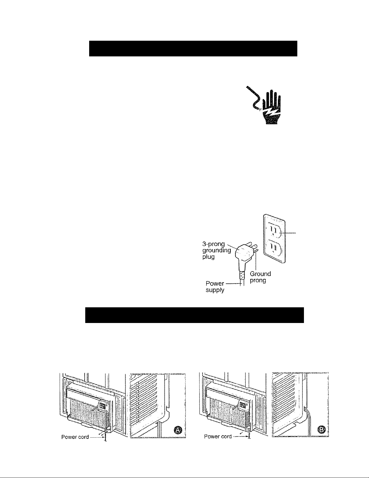
• Be sure the air conditioner is properly grounded.
To minimize shock and fire hazards, proper
grounding is important. The power cord is
equipped with a three-prong grounding plug for
protection against shock hazards,
«Your air conditioner must be plugged into in a
properly grounded wall receptacle. It the wall
receptacle you intend to use is not adequately
grounded or protected by a time delay fuse or
circuit breaker, have a qualified electrician install
the proper receptacle.
• Do not run air conditioner with a protective
covering. This could result in mechanical damage
within the air conditioner
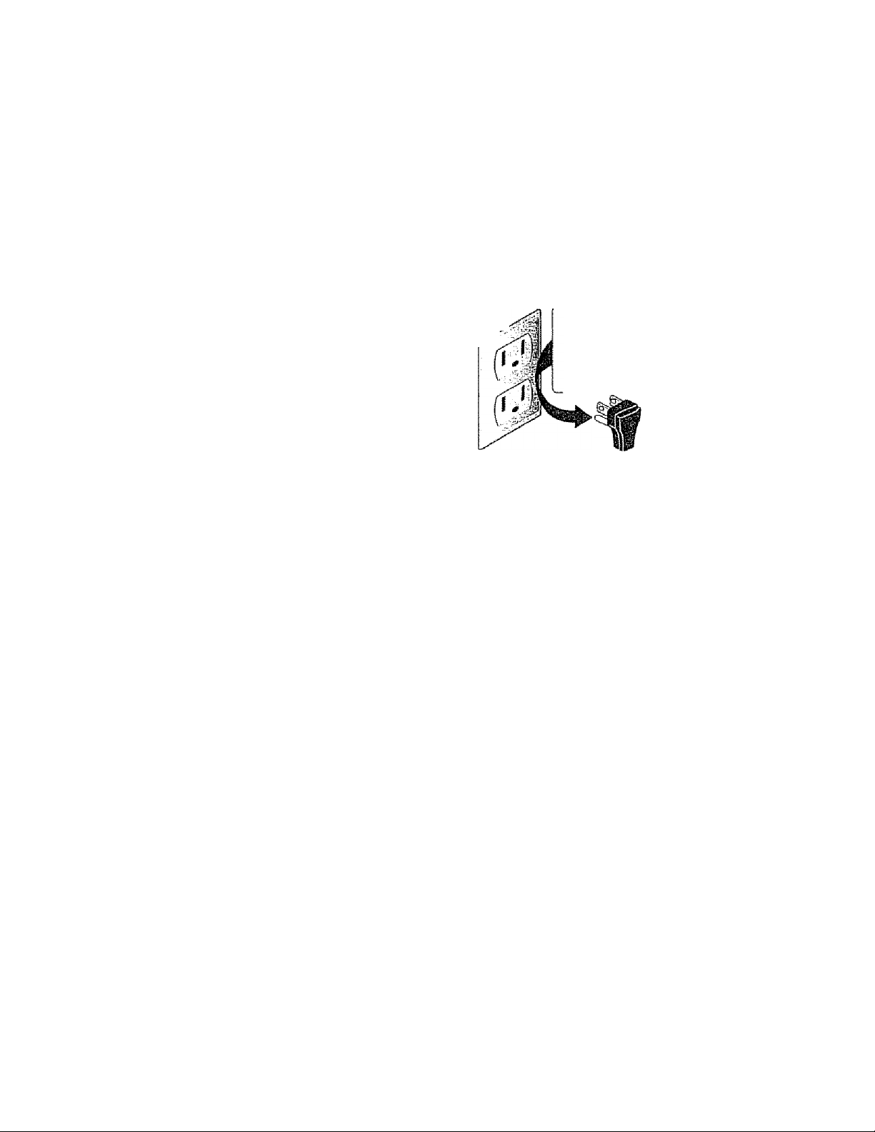
«Do not use an extension cord or an adapter
plug.
Do not use an extension cord or an adapter plug.
Do not remove any prong from the power cord.
Grounding type
wall receptacig.
ENERGY SAVING IDEAS
• The capacity of the room air conditioner must fit
the room size for efficient and satisfactory
Operation.
• Install the room air conditioner on the shady side
of your home. A window that faces north is best
because it Is shaded most of the day.
• Do not block air flow inside with blinds, curtains, or
furniture, or outside with shrubs, enclosures, or
other buildings.
• Close the floor and wall registers and the fireplace
damper so cool air does not escape up the
chimney and into the duct work,,
• Keep blinds and drapes in other windows closed
during the sunniest part of the day
• Clean the air filter as recommended in the
MAINTENANCE section of this manual
• Proper insulation and weather stripping in your
home will help keep warm air out and cool air In.
" External house shading with trees, plants or
awnings will help reduce the air conditioner's work
load.
• Operate heat producing appliances such as
ranges, washers, dryers, and dishwashers during
the coolest part of the day
13 Avoid fire hazard or electric shock.
Do not, under any
Gircumstances, cut,
remove, or bypass
the grounding prong
from this plug.
Power supply cord 1
with 3-prong
grounding plug
-3-
Page 4
ELECTRICAL REQUIREMENTS
OBSERVE ALL LOCAL CODES AND ORDINANCES.
DO NOT, UNDER ANY CIRCUMSTANCES,
REMOVE THE POWER SUPPLY CORD
GROUND PRONG.
electrical GROUND IS REQUIRED ON
THIS APPLIANCE.
A 115-vott 60 Hz, AC only, 15A fused and
properly grounded electrical supply is required,
A time delay fuse or time delay circuit breaker
is recommended. Use a dedicated circuit,
serving only this appliance,
DO NOT USE AN EXTENSION CORD.
RECOMMENDED GROUNDING METHOD
For your personal safety, this appliance must
be grounded. This appliance has a power
supply g 3"prong grounding plug. To
minimize possible shock hazard, the cord must
be plugged into a mating grounding type wall
receptacle and grounded in accordance with
the National Electrical Code {ANSI/NFPA 70)
latest edition and all local codes and
ordinances. If a mating wall receptacle is not
available, it is the personal responsibility and
obligation of the customer to have a properly
grounded 3-prong wall receptacle installed by a
qualified electrician.
AWÄRNING
Electrical Shock Hazard
Plug into a grounded 3 prong outlet.
Do not remove ground prong.
Do not use an adapter
Do not use an extension cord.
Failure to follow these instructions can result
in death, fire, or electrica! shock.
■3-prong
grounding
type wall
receptacle
cord
INSTALLING THE POWER CORD
You can choose between two methods below according to your window stool shape and preference.
USING SLIT "A” USING SLIT "B"
Fasten the stopper using 2 screw holes, and lead Fasten the stopper using left screw hole, and rotate
out the power cord through slit "A". properly to lead the power cord out through slit “B"
- ¿j. ■
Page 5
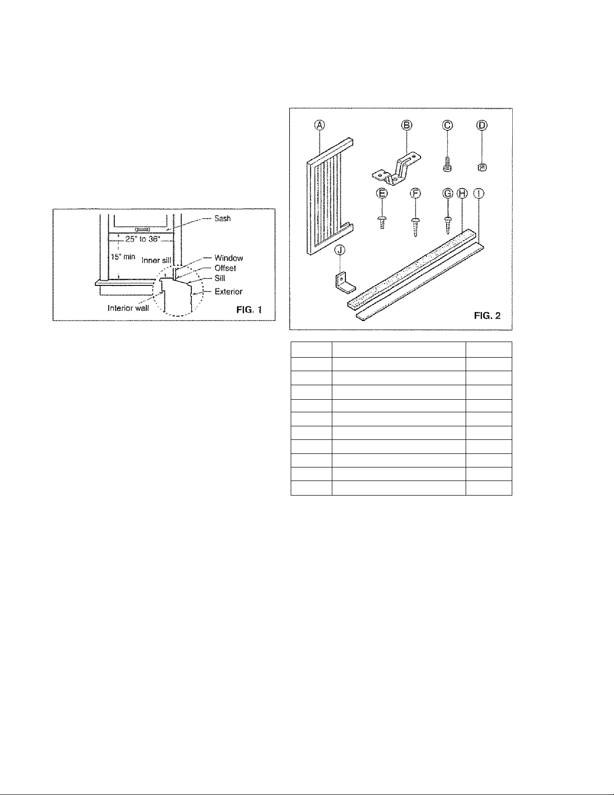
INSTALLATION REQUIREMENTS installation hardware
Your air condttfoner wil! install into standard double hung
windows with actual dear opening widths of 25 to 36
inches (635mm to 9l4mm) {FIG 1)
Lower sash must open sufficiently to ailow a clear
verlicai opening of 15 inches (381mm).. Side louvers
and the rear of the air conditioner must have dear
air space to allow enough airflow through the
príndAn^íPr fnr hppf rpmn\/Al THa tpat rtf fhp Jinif
f I I «4/4 J Í tk I I I 1%!./ ■ a l.> If l\.# i eS'Ciij \J I LI I ^4# l-iCl I E V
must be outdoors, not inside a building or garage.
pi cpTDir*AI CiFRVirF
Check your available electrical service. The power
supply available must be the same as that shown
on the unit nameplate {found on right side of cabinet)
All models are equipped with a 3-prong service plug
to provide proper service and safe positive
grounding. Do not change plug in any way Do not
use an adapter plug. If your present wall outlet does
not match your plug, call a qualified electrician to
make the necessary corrections,
SAVE CARTON and this OWNER'S MANUAL for
future reference. The carton is the best way to store
unit during winter or when not in use.
* •
ITEM
A
y
0
NAME OF PARTS Q'TY
SIDE CURTAIN
SILL SUPPORT 2
C BOLT 2
D LOCK NUT
E SCREW: 25/64" 13
p
SCREW: 5/8"
G SCREW: 5/8" 5
H FOAM STRIP 1
1 FOAM SEAL 1
J
L BRACKET 1
2
2
3
To avoid risk of personal injury, property damage,
or product damage due to the weight of this
device and sharp edges that may be exposed!
• Air conditioners covered in this manuai pose an
excessive weight hazard Two or more people
are needed to move and instail the unit,
To prevent injury or strain, use proper lifting and
carrying techniques when moving unit,.
»Carefully inspect location where air conditioner
will be installed. Be sure it will support the
weight of the unit over an extended period of
time.
■ Handle air conditioner with care. Wear
protective gloves whenever lifting or carrying the
unit. AVOID the sharp metal fins of front and
rear coils.
»Make sure air conditioner does not fall during
installation.
REQUIRED TOOLS:
. Tight Fitting gioves
• Standard screwdriver
• Phillips screwdriver
• Pliers
• Sharp knife
• 3/8-inch open end wrench or adjustable wrench
• 1/4-inch hex socket and ratcher
• Tape measure
»Electric drill
»1/4-inch drill bit
-5
Page 6
INSTALLATION
Pick a location which will aiiow you to biow the cold
air into the area you want. Windows used for
installation must be strong enough to support the
weight of the air conditioner, Good installation with
special attention to the proper position of the unit
will lessen the chance that service will be needed-
When cooling more than one room, installation
location is very important To cool your rooms, cold
air must be blown from the air conditioner in a
straight path.
HOW TO INSTALL
If the air conditioner is blocked by a storm window frame,
see step t9 on page 8 before beginning to instait
EB Remove the screws which fasten the cabinet at
both sides and at the back. Save side screws.
Discard back screws.
“V
Carefully place the cabinet on the window inner sill
and align the center of the cabinet front with the
center line marked in the window Inner sili.
llllift
Slide the unit out of the cabinet by gripping the
base pan handle and pull forward while bracing the
cabinet.
' 3 -'-Ê ■ !
FiG. 4
H Cut the FOAM SEAL (ITEM 1) to fit the
underside of the window sash. Peel off the backing
and attach the FOAM SEAL as shown in Fig, 5.
'-Sash
^ FIG. 5
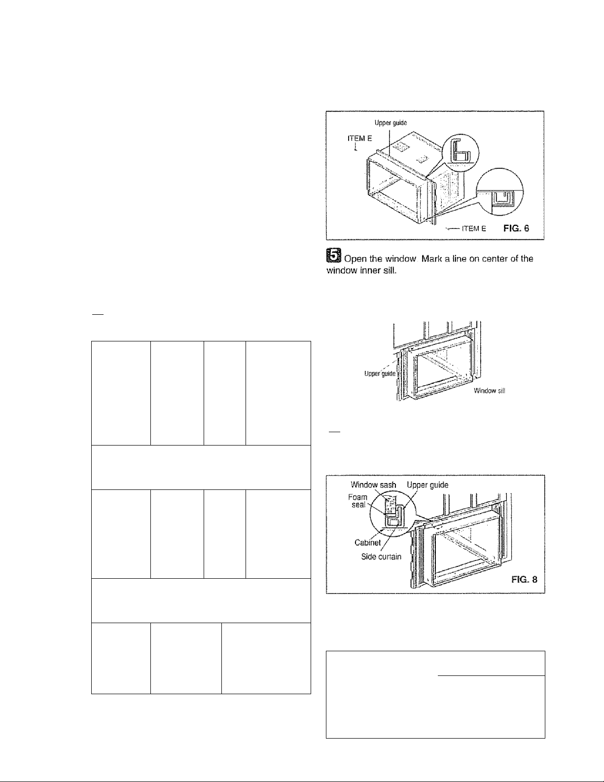
fej Insert the side curtain (ITEM A) into the upper
guide and lower guide of the air conditioner,, Fasten
the curtains to the unit with screws (ITEM E).
FIG. 7
l,",l Puli the bottom window sash down behind the
upper guide until they meet
NOTE; Do not pull the window sash down so tightly
that the movement of side curtain is restricted.
Loosely assemble the sill supports using the
parts in FIG, 9.
INDOOR ==^
item'd
^p======ç= OUTDOOR
^ ITEM В
ITEM 0
FIG. 9
6 ^
Page 7
__
Select the position that wilt place the sill supports
near the outermost point on sill (FIG. 10)
Attach the sill supports to the cabinet track hole
closest to the selected position using screw (ITEM E).
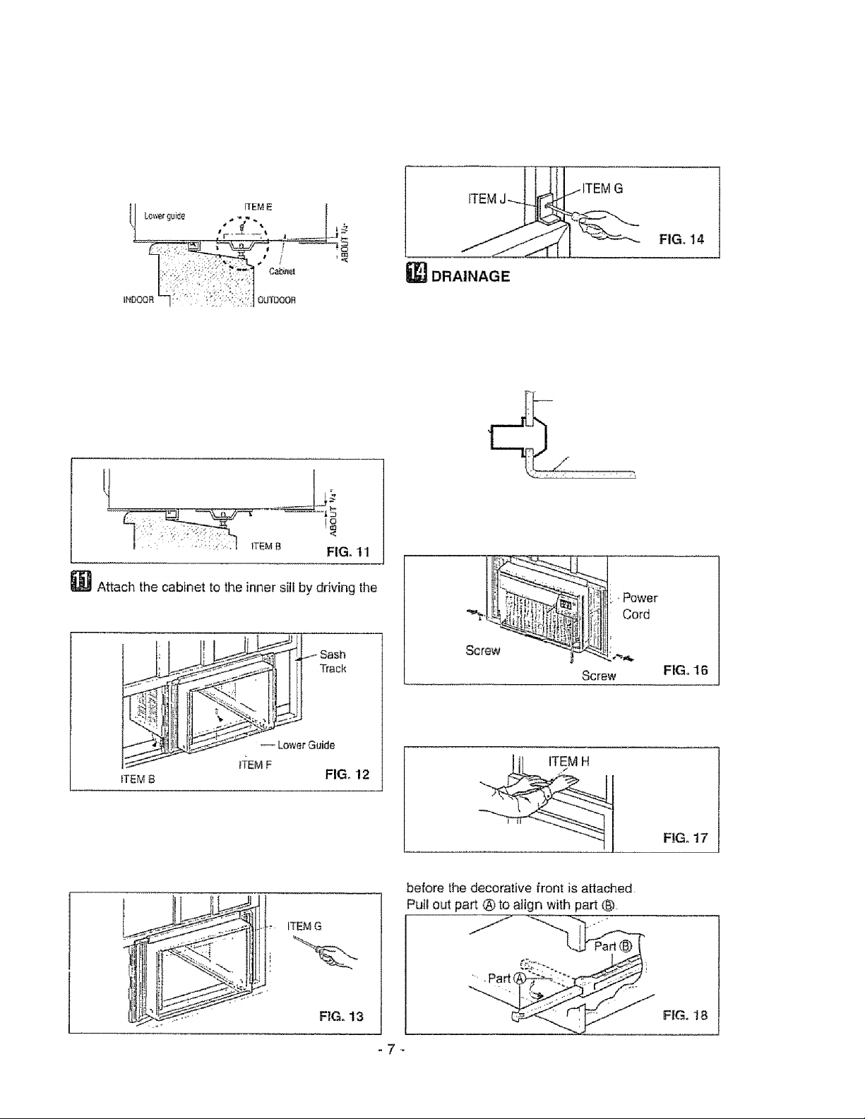
Attach the i BRACKET (ITEM J) with screw
ТЕМ G). (FIG. 14)
FIG. 10
Place the sill supports with the cabinet on the
window sill's selected position.
The cabinet should be installed with a very
slight tilt (about 1/4") downward toward the outside
(FIG. 11).
Adjust the bolts and the nuts of sil! supports to level
the cabinet.
screws (ITEM F) through the front angle into the
window inner sill (FIG. 12).
0e sure to insert the drain pipe into base pan before
installation.
The air conditioner must be installed with a slight tilt
downward to the outside for proper water drainage.
The air conditioner will drain the excess condensed
water through the drain pipe, (FIG. 15)
BASE PAN REAR
DRAIN PIPE
BASE PAN BOTTOM
FIG. 15
Slide the chassis into the cabinet (FIG. 16)
CAUTION: For security purposes, reinstall side
screws you removed in step 1.
Cut the foam strip (ITEM H) to the proper length
and inserí between the upper window sash and the
lower window sash. (FIG. 17)
Pul! each side curtain fully to each side of
window opening.
Attach each side curtain to the window sash using
screws (ITEM G), (FIG, 13)
I The vent control handle must be straightened
Page 8
INSTALLATION
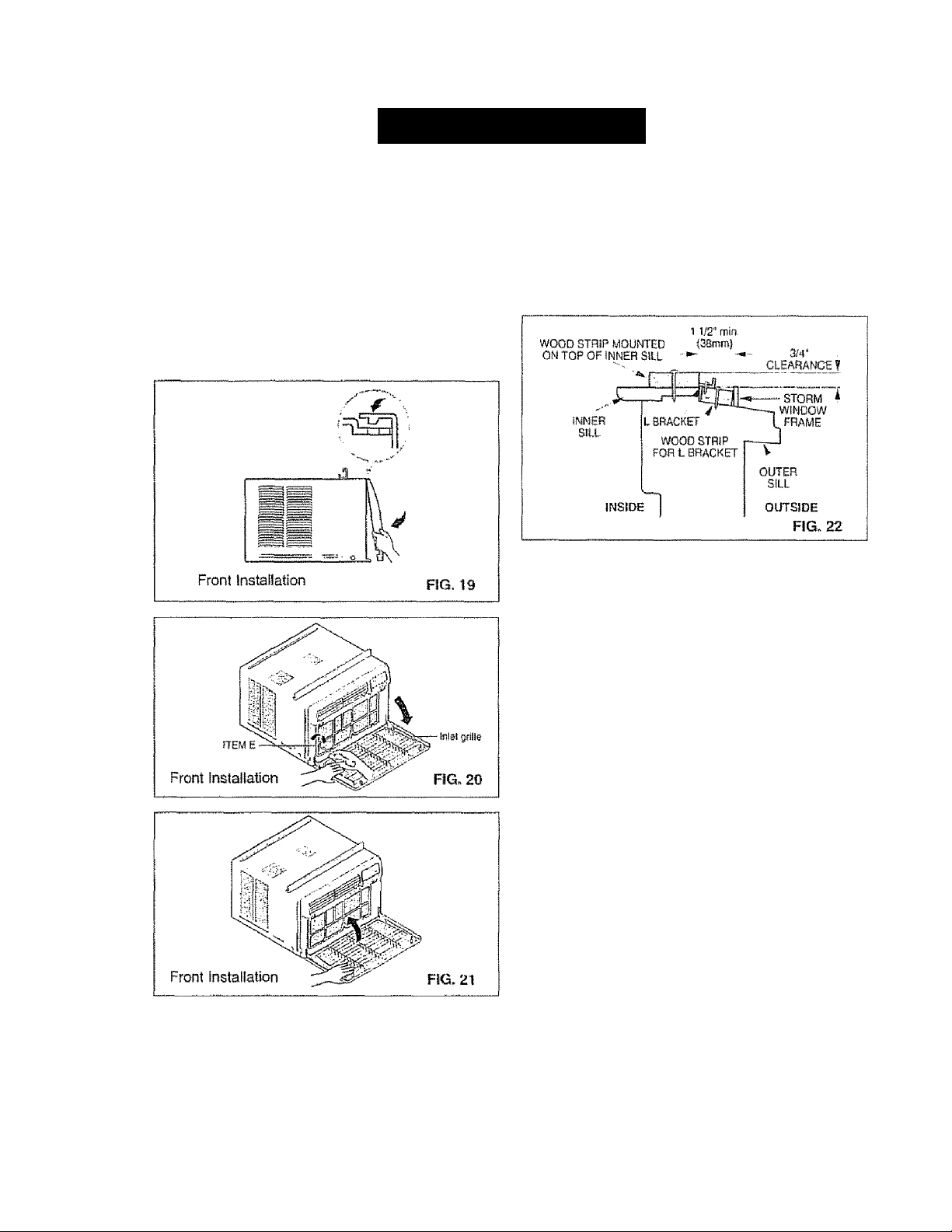
FRONT INSTALLATION
m
Install the front grillefpacked separately) onto the
cabinet as follows:
■> Hook upper tabs of front grille into slots on the
cabinet top. (FIG. 19)
“ Push front grtile’s tips towards the cabinet in order
to snap side tabs into the cabinet. (FIG. 19)
• Open the inlet grille. (FIG. 20)
• Install the screw (ITEM E) through the front grille,
(FIG. 20}
• Close inlet grille. (FIG. 21}
Top of wood strip should be approximately 3/4"
higher than the storm window frame to help
condensation to drain properly to the outside.
■ Install a second wood strip (approximately 6" long by
1V2" wide and same thickness as first strip) in the
center of the outer sill flush against the back of the
inner sill. Screw the L brackets info this strip..
This will raise the L bracket as shown in FIG, 22,
REMOVAL FROM WINDOW
• Turn off and unplug the air conditioner
• Remove the front grille, See HOW TO REMOVE THE
FRONT GRILLE - Refer to page 13,
• Unscrew the side screws that you installed in Step 15
• Slide the air conditioner out of the cabinet.
BE CAREFUL NOT TO DROP IT,. Hold onto it firmly the
whole way sliding it out Once removed, set it safety out
of the way
• Remove the L bracket from window frame and the sash
seal from between the windows
• Unscrew the side curtains from the window frame Fold
them back to the sides of the cabinet,,
• Remove screws attaching cabinet to inner sill Be careful
not to let cabinet fall once screws are removed
• Remove cabinet from window opening.
• Place air conditioner into cabinet. Reinstall side screws
and Front Grille
• Place unit and all assembly hardware in air conditioner
shipping carton, and store in clean, dry place
* •
i] IF AIR CONDITIONER IS BLOCKED BY
E
STORM WINDOW FRAME
• If storm window presents interference, fasten a 2“
wide wood strip to the inner window sill across the full
width of the sill The wood strip should be thick
enough to raise the height of the window sill so that
the unit can be installed without interference from the
the storm window frame. See FIG, 22
' Air conditioners covered in this manual pose an
excessive weight hazard. Two or more people
are needed to move and install the unit.
To prevent injury or strain, use proper lifting and
carrying techniques when moving unit
• When handling the air conditioner, be careful to
avoid cuts from sharp metal fins on front and
rear coils..
* Make sure air conditioner does not fall during
removal
-8-
Page 9
HOW ÄND WHY
Your room air conditioner provides the foliowing
functions to make hot weather living more
cornfortable:
» Cools and circulates room air.,
• Lowers humidity by removing excess moisture,
• Filters out summertime dust, dirt, and some
airborne impurities.
The air conditioner performs these functions by
drawing room air through a filter which traps dust
di lU Lin L üd.1 tiwitrb u I E Id dli Indl f pabbdb Uvxsi a,
cooling coil which refrigerates the air and removes
excess moisture. The same air is then returned to
the room- cooler, drier, and cleaner, Moisture
removed from the room air is carried to the outside
and evaporated..
Your air conditioner is designed to be easy to
operate and to provide plenty of cooling power.
NORIVIÄL SOUNDS fig. 23
Aside from the regular fan motor and compressor
sounds coming from your air conditioner, you will
once in a while hear a pinging sound. This is the
result of moisture being picked up from the air in the
room and thrown against the air conditioner’s fan.
This is normal and should not be cause for concern.
Also, do not be aiarmed if you hear a slight hissing
or gurgling sound coming from your air conditioner
after it is off. These are normal coolant noises.
- Compressor
The modern high efficiency
compressor may have a high
pitched hum or pulsating
noise that cycles on and off,
Unit Vibration
The unit may vibrate
and make noise
because of poor wall
or window construction.
Fart
You may hear air
movement from
the fan.
Condenser
You may hear droplets of water hitting
the condenser causing a pinging or
clicking sound.
FIG. 23
CAPACITY AND RUNNING TIME
Proper unit size is important in deciding the desired
comfort for the area you want to cool. An
undersized unit wili not have the capability to cool,
leaving the area uncomfortably warm. The proper
size Is determined by the number of square feet in
the area to be cooled, indoor and outdoor
temperature and humidity
Whenever the heat or humidity load is above normal
the air conditioner must run longer and more often
^Q/зг\ tHo HcJ6г:!гcs/^ ^omг^csгE^t^ iro coIq/'IoH
to
Under heavy heat load conditions the air conditioner
may need to run constantly to keep the temperature
you want
At times using the MED FAN setting to circulate the
room air may make it comfortable even though the
air is not being cooled. This will decrease your cost
of use
LHtJ UcJbiftiU wllllJcitCilUICi ywU itClVc bCiCvItJUt
-9-
Page 10
FEATURES
USING THE AIR CONDITIONER
liHiit
shock, or injury to persons, read the important
SAFETY instructions section before operating this
appliance
To reduce the risk of fire, electric
To begin operating the air conditioner after
instafiation, follow these steps:
1, Pfug in the air conditioner. (To prevent eiectrical
hazards, do not use an extension cord or an
adapter plug.)
2,. Set the exhaust vent to the CLOSE position.
3. Set the TEMP Control to the coolest setting.
4 Set the MODE control at the highest COOL level
5. Adjust the louvers for comfortable air flow.
6, Once the room has cooled, adjust the TEMP and
Mode Control to the setting you find most
comfortable
NOTE : If the air conditioner is turned off, wait 3
minutes before restarting. This allows pressure
inside the compressor to equalize. Failure to wait 3
minutes before restarting may cause inefficient
operation.
If you move the TEMP Control to a warmer, then
Immediately back to a cooler setting, the unit will
shut off,- Wait 3 minutes before restarting,
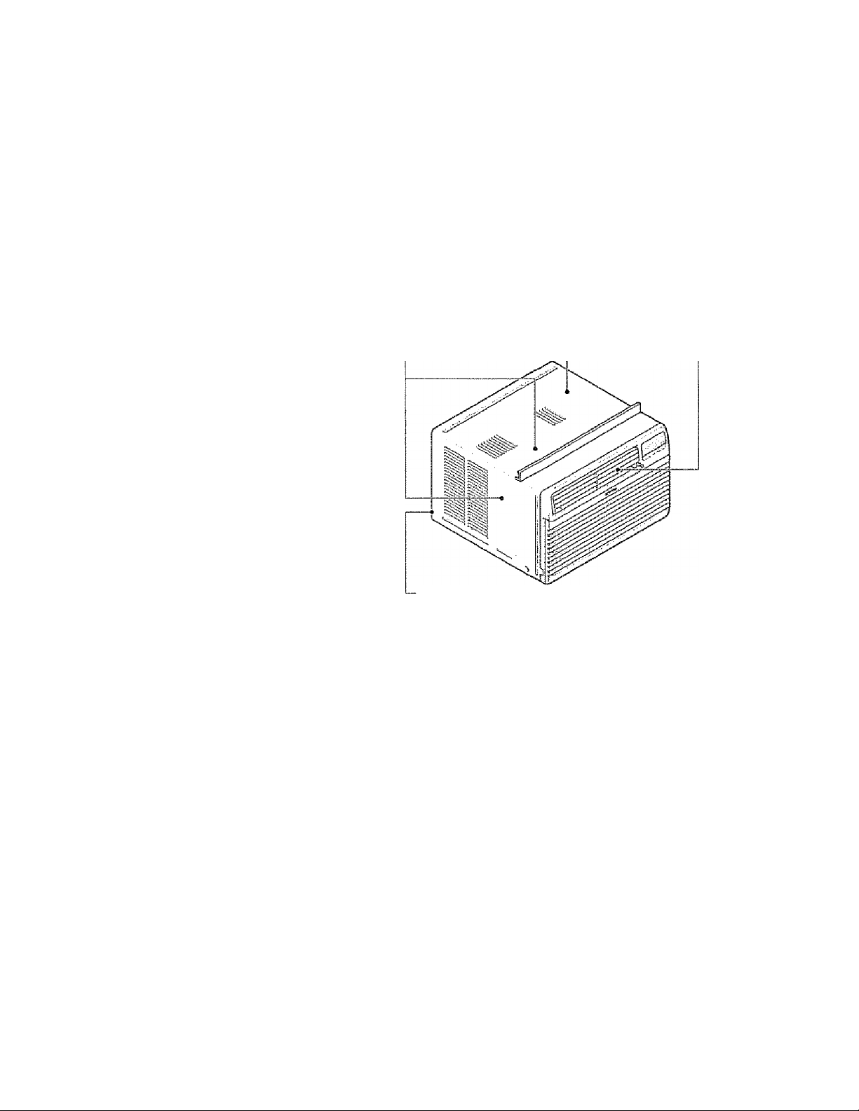
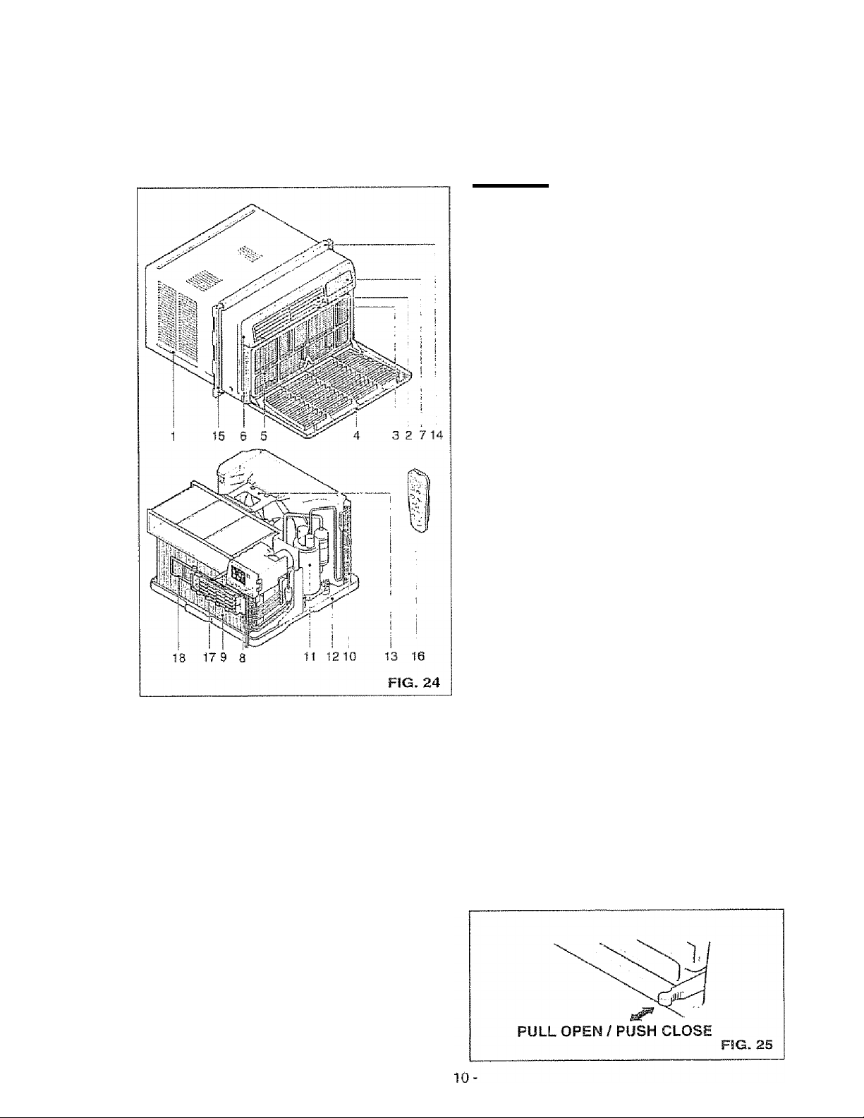
1 Cabinet
2. Verticaf Air
Direction Louvers
3. HorKontai Air
Direction Louvers
4. inlet Grille
5. Air Filter
6. Front Grille
7. Control Board
8 Power Cord
9. Evaporator Coil
10, Condenser
11, Compressor
12, Base pan
13 Brace
14,, Upper Guide
15. Curtain
16 Remote Control
17, Air Purifying Filter
IS, Case, Filter
VENT CONTROL
The Vent Control allows the air conditioner to
either recirculate inside air (CLOSE) or exhaust
air to the outside (OPEN) (FIG 25)
• The CLOSE position is used when maximum
cooling is desired. It may also be used for air
recirculation without cooling when the air
conditioner is set in the FAN position,,
«The OPEN position removes stale air from the
room and exhausts it to the outside. Fresh air is
drawn into the room through your home's
normal air passages.
• The OPEN or CLOSE position can be used with
any fan selection.
Page 11
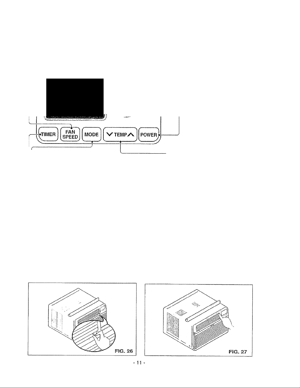
DISPLAY
rFAN SPEED
Every time you push this button, it advances the setting as follows: {High -i- Low Med High)
.......................................... ............................ REMOTE CONTROL
COOL FAN , -
SIGNAL RECEIVER
FAN E„g„gy
SAVEfl
tMDOOR OESIREO MR
firi nn P^JЙÍF!EЙ
HH HH
и и ÌJLJ RESTART P tAS;M Ai г e
MODE
- Every time you push this button, it will shift among
COOL. ENERGY SAVER and FAN.
- ENERGY SAVER:
• The fan stops when the compressor stops cooling
ApproKimately every 3 minutes the fan will turn on and
check the room air to determine if cooling is needed,
- SHUT-OFF TIME
• if unit is running, Timer sets number of hours until shut-off.
• Every lime you push Timer button, it advances the Timer selling as follows: 1 Hour •
-
• If unit is off, Timer sets number of hours before unit starts
• Every time you push Timer button, it advances the Timer setting as follows: 1 Hour -
TEMPERATURE SETTING
" This button can automatically controi
the temperature of the room.
The temperature can be set within a
range of 60°F to se^F by increments of 1®F
POWER
• To turn the air conditioner ON,
» This button takes priority over
* When you first turn it on, the
' 2 Hours -
2 Hours -
push the button. To turn the
air conditioner OFF, push
the button again,
any other button
air conditioner is on the
High cool mode and the Temp
at72"F
12 Hours maximum
12 Hours maxlmum.
HORIZONTAL AIR DIRECTION CONTROL
The horizontal air direction is adjusted by moving
the vertical louvers right and ieft with your
fingertips. (FiG- 26)
VERTICAL AIR DIRECTION CONTROL
The vertical air direction is adjusted by moving the
horizontal louvers up and down with your fingertips,
(F!G„ 27}
Page 12
REMOTE CONTROL
NOTE: The Remote Control will not operate properly if strong light shines on the sensor window of the Air
Conditioner or if there are obstacles between the Remote Control and the Air Conditioner.
Every time you push button, you will hear a beep from the Air Conditioner.
POWER
• To turn lha air conditioner ON, push the button To turn the air conditioner OFF,
push the button again. This button takes priority over any other button
When you first turn It on. the air conditioner is on the High cool mode and the Temp at 72°F
AlRPURiFIER —
• Press the Air Purifier button Operation will start at low speed when the button is pressed
and stop when the button is pressed again.
' Set the fan speed with the remote control
• You can select Air Purifier function without cooling. Fan spaed will at first be low
Increase fan speed by pressing Fan Speed button
----------—------------—-----------------
---------
---
---------------------------------
——
........................................
------
--------------
-----
TEMPERATURE SETTING------------------------------------------------------
• This button can autornaticalty control the temperature of the room.
The temperature can be set within a range of 60’F to 86°F by increments of 1®F
FAN SPEED ...........................
* Every lime you push this butlort it advances the setting as follows:
{High - Low -* * Med -> High}
SLEEP MODE
• Press the Sleep button to set the lime you want the unit to turn of! automatically
• For your sleeping comfort, once Timer is set. the Temperature setting will raise by 2‘F
after 30 min , and 2‘F after another 30 min
• Every time you push this button, the remaining tims wilt be set as follows
{iHoUr “> 2Hours 3Hours »4Hours ► SHours • 6HoufS • 7Hours - OHours
- 1 Hour ' ■ 2Hours - )
TIMER
---------------------------------------------------------------------------------------
- SHUT-OFF TIME
• If unit is running. Timer sets number of hours until shut-off
• Every lime you push Timer button, it advances the Timer setting as follows: 1 Hour -* 2 Hours -
- START TIME
• it unit is off, Timer sets number ol hours before unit starts
• Every time you push Timer button, it advances the Timer setting as foHows: 1 Hour •> 2 Hours
-----
—---------—
..................—
---
..........................
------—------------
.......................
—
~--------------
i AIR
■. PUHÍFÍEH POWER
V TEMP A
! ~y
Ì
FAN SPEED
S SLEEP MODE
TIMER
^ '''»Wh—.1*^
12 Hours maximum
- 12 Hours maximum -
—L
V»—/
MODE
--------------------------------------------------------------------------------------------------------------
- Every time you push this button, it will shift among COOL. ENERGY SAVER and FAN
- ENERGY SAVER
• The fan stops when the compressor stops cooling
Approximately every 3 minutes the fan will turn on and check the room air to determine if cooling is needed
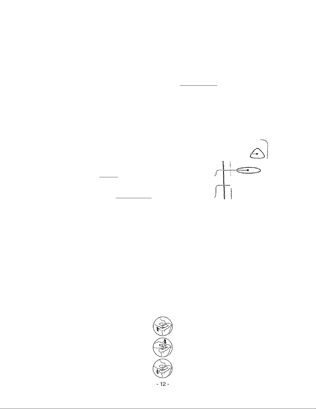
HOW TO INSERT BATTERIES
Remove the cover from the back of the
remote controller.
Insert two batteries.
" Be sure that the (+) and (-) directions
are correct.
" Be sure that both batteries are new.
Re-altach the cover.
' Do not use rechargeable batteries..
Such batteries
differ from standard dry cells in
shape, dimensions, and
performance.,
> Remove the batteries from the
remote controller if the air
conditioner is not going to be used
for an extended length of time.
Page 13

AIR FILTER CLEANING
The Air Filter vs/flt become dirty as it removes dust
from the inside air It should be washed at least
every 2 weeks - if the Air Filter remains full of dust,
the air flow will decrease and the cooling capacity
will be reduced, possibly damaging the unit
• Pull the inlet grille forward, grasping both tabs,
then pull out the air filter (FIG. 28)
■> Wash the Air Filter under the faucet with warm
water Be sure to shake off all the water before
replacing the filter (FIG,29)
AIR PURIFYING FILTER CLEANING
CAUTION: To avoid possible minor electric
A
shock, do not touch Air Purifying Filter within
10 seconds after opening inlet grille,
To ensure continued peak efficiency, the condenser
coils (outdoor side at the unit) should be checked
periodically and cleaned if they become clogged
with soot or dirt from the atmosphere. Brush or
vacuum exterior coils to remove debris from fins.
HOW TO REMOVE THE FRONT GRILLE
• open the Inlet grille downward.
“ Remove the screw securing the Front Grille.
• Push the grille up from the bottom and pull the top
of the grille away from the case to lift the top tabs
out of their slots.
The Air Purifying filter behind the air filter should be
checked and cleaned once every 3 months or more often
if necessary
»After removing the air filter, pull Air Purifying filter
slightly forward to remove ,
‘ Dip the Air Purifyirtg filter into water mixed with neutral
detergent for 20-30 minutes-
»The Air Purifying Filter must be completely dry before
reinstalling it into the Air Conditioner,
» Re-fnstali the Air Purifying tiller to the original position
AIR CONDITIONER CLEANING
Clean the front grille and inlet grille by wiping with a
cloth dampened in a mild detergent solution,.
The cabinet may be washed with mild soap or
detergent and lukewarm water, then polished with
liquid appliance wax.
HOW TO REPLACE THE FRONT GRILLE
Attach the front grille to the cabinet by inserting the
tabs on the grille into the slots on the front of the
cabinet,. Push the grille in until it snaps into piace.
- 13-
Page 14

BEFORE CALLING FOR SERVICE
Check the foltowing list to be sure a service call is really necessary A quick reference to this manual may
help you avoid an unneeded service cal!.
THE AIR CONDITIONER WILL NOT OPERATE
Check if... Then...
Wall ptug disconnected.
House fuse blown or circuit breaker tripped.
Power is OFF,
Unit was fumed off and then on too quickly.
TEMP Control set waimer than room temperature.
AIR FROM UNIT DOES NOT FEEL COLD ENOUGH.
Check if... Then...
FAN SPEED set at LOW.
TEMP ConW set too warm.
Room temperature below TOT {21 "C).
Temperature sensing tube touching evaporator coil,
located behind front grie
■me AIR CONDmONER COOUNG, BUT ROOM [S TOO WA
Check if.,.
Push plug lirnily into wail outlet.
Replace iuse with lime delay type or reset circuit breaker.
Push the power button.
Set unit off and wait 3 minutes before restarting,
Set TEMP Control to tower temperature.
Push FAN SPEED button to set at Hi.
Set TEMP Control to a lower temperature.
Cooling may not occur until room temperature rises above 70^F [21 ®G).
Straighten tube away from evaporator coil
m - ICE FORMING ON COOUNG COIL BEHIND FRONT GRILLE.
Then...
Outdoor temperature beiow 70T {21 'C)
Air filler may be dirty
TEMP Control set too cold lor night-time cooling
To defrost the coii, set the MODE to FAN
Clean air filter. Refer to Maintenance section of owneris manual,
To defrost the coil, set (he MODE to FAN or "High Cool" with the
TEMP control to hiaher terriDerature,
THE AIR CONDITiONER COOLING, BUT ROOM IS TOO WARM.
Check 11.. Then...
Dirty air liitef - air restricted.
TEMP Control set too warm.
Front of unit is blocked by drapes, blinds, furniture, etc
Air distribution is restilcled.
Doors, windows, registers, etc. open. Cold air escapes.
Unit recently turned on in hoi room.
Clean air tier. Refer to Maintenance section of owner's manual
Set TEMP Control to lower temperature.
Clear blockage In front o! unll
Close doors, windows, registers, eta.
Allow additional time to remove stored heat item walls, ceiling, lloor, and furniture.
THE AIR CONDITIONER TURNS ON AND OFF RAPIDLY.
Check if... Then...
Outside temperature is extremely hot
Set FAN SPEED on HI to bring air past cooling coils faster
NOISE WHEN UNIT IS COOLING.
Check if... Then...
Sound of fan ling water Irom the ntoisture removal system,
Window vibrato - poor Irtslallaiiort.
This is normal when humidity is high. Close doors, windows, and registers.
Refer to installation instructions or check with installer.
WATER DRIPPING INSIDE ROOM WHEN UNIT IS COOLING.
Check if... Then.,.
The air conditioner is improperly installed
Tilt air conditioner slightiy to Iho otilside to allow water drainage Refer to
irrstallalion instructions or check with inslatler
WATER DRIPPING OUTSIDE WHEN UNIT IS COOLING. Check if... Then...
The unit Is removing large quantities of moislurs
from humid room.
This is normal dsjring excessively humid days
. 14.
Page 15

15-
Page 16

Room Air Conditioner To order Parts call Toll Free
Model No. 580.72089200 1 -800-4-MY-HOME"^(1 -800-469^4663)
CAUTION: Use the Kenmore part number on all orders, not the illustration number.
CABINET & FRONT GRILLE ASSEMBLY
3-A
12/01
16
Page 17

580 72089200
CAUTION; Use the Kenmore part number on all orders, not the illustration number
CABINET & FRONT GRILLE ASSEMBLY
ILLUSTRATION
NUMBER
1 * A
2-A
3 ■ A
4-A
5 - A
6 - A
7-A
8-A
9-Á 385QA20242S
*
PART NUMBER DESCRIPTION
3530A20043A
3530A20046A
5231A20006A
44S8A20019A
4758A20016A
4758A20016B
3091AR2317J
4974AR3328C
3828A20133P
FRONT GRILLE
INLET GRILLE
AIR FILTER ASSEMBLY
VANE
LOUVER
LOUVER
CABINET ASSEMBLY
1 ipDIZn r^l liniT
LJr i til vsL/IL/iZ.
1 APPI PMPnniV
MANUAL OWNER’S
# = Functional Parts
* = Non-iliustraied Parts
17
12/01
Page 18

580 72089200
CAUTION: Use the Kenmore part number on ail orders, oot the illustration number.
CONTROL BOX ASSEMBLY
10-B 3-B
6^B
12-t
7-B
14„B
12/01
-18-
Page 19

580.72089200
CAUTION: Use the Kenmore part number on all orders, nM the illustration number.,
CONTROL BOX ASSEMBLY
.USTRATION
NUMBER
1 -B #
2-B
3- В
4- В
5- В
в ” В
"7 D
/ - D
8 - В #
9 -В
10-В
11 - в
12 - в
13-8
14 - В
15 - В
PART NUMBER
4994A10029A
3720A10061A
3550A30114A
6871A20167A
6871A20168B
6120AR2359V
6609A10003G
6411A20011F
6323A20004D
6631AR3843U
6850A90001G
6631A30003A
6601A30002A
6711A20053B
3790A20021B
DESCRIPTION
CONTROL BOX
PANEL CONTROL
COVER CONTROL BOX
PWB ASSEMBLY. AC
PWB ASSEMBLY DC
CAPACITOR
H.V ASSEMBLY
POWER CORD ASSEMBLY
THERMISTOR ASSEMBLY
CONNECTOR ASSEMBLY
CABLE FLAT
CONNECTOR ASSEMBLY
SWITCH ASSEMBLY
REMOTE CONTROL
WINDOW DISPLAY
# = Functional Parts
* = NonHIlustrated Parts
^ 19
12/01
Page 20

580.72089200
CAUTION: Use the Kenmore part number on ail orders, not the illustration number.
AIR HANDUNG & CYCLE PARTS
17-C
18-C
12/01
16-C
15-C
20-
Page 21

580,72089200
CAUTION; Use the Kenmore part number on all orders, noi the illustration number.
MB HANDLING & CYCLE PARTS
USTFIATtON PART NUMBER DESCRIPTION
NUMBER
1 -C 3041A20021N BASE PAN WELD ASSEMBLY
SPSfiÂPnnnTA
2-C
3-C
JiMi viC’lii f f «
4681A20027X
AIR GUIDE LOWER
^/i0Tr\0 AQCCTK/ini V
iVfO 1 wli AoOCiVIljLT
4-C
5- C # 3H02932B CLAMP SPRING
6-C #
7- C # 5421A10026A EVAPORATOR ASSEMBLY
8- C
9-C
10-C 5403A20043M CONDENSER ASSEMBLY
11 - C
12-C
13-C
14-C
15-C
16 - c
17 -C
18 -C
19 -C 5983A10009H PLASMA FILTER ASSEMBLY
5900A20020A
4948A10014A
4998A10012A
5900AR1167B
4800A30002A
6238A20009A
4900A20003A
4H02023A
4H01029D
3H02773A
3530A20009H
3110A20042A
FAN. TURBO
ORIFICE
SHROUD
FAN
CjD Ar'C
iDHAwIZu
AID /ti! HnD Ì IDDDD
Ain LnUiUtl Urrcn
VENTILATION DAMPER
DRAIN RUBBER
WASHER RUBBER
DRAIN PIPE
GRILLE ASSEMBLY, REAR
C|| "TfCQ OAQD
1 IL» I C ii
# = Functional Parts
* = Non-illusirated Parts
-21 - 12/01
Page 22

580J2089200
CAUTION; Use the Kenmore pari number on all orders, ngt the illustration number.
COMPRESSOR PARTS
9-D
8-D
6-D-
1 3“D
5-D
10-D
12/01
22 ■
Page 23

580 72089200
CAUTION; Use the Kenmore part number on all orders, mpt the illustration number,
COMPRESSOR PARTS
,USTRATION
NUMBER
1 - D
2-D #
3 ' D
4-D
5 - D
6 - D #
7- D
8- D
9- D
10- D
11 - D
12- D
13- D
PART NUMBER
4984AR4335A
6416A90007A
4810AR4155B
1NHA0801206
4986A30001A
6750A30001N
3550A30048A
4H01058A
4H00947A
5211A10074D
5211A20228F
6211A20470B
5211AR3332Y
DESCRiPTiON
ISOLATOR, COMP
COMPRESSOR
BRACKET, WASHER
HEXAGON NUTS
GASKET
OVERLOAD PROTECTOR
TERMINAL COVER
GASKET NUT
TERMINAL COVER NUT
TUBE ASSEMBLY DISCHARGE
TUBE ASSEMBLY SUCTÍON
TUBE ASSEMBLY EVAPORATOR
TUBE ASSEMBLY CONNECTOR
# = Functional Parts
* = Non-lilustrated Parts
- ¿Ó -
12/01
Page 24

580 72089200
CAUTION; Use the Kenmore part number on all orders, noi the illustration number.
INSTALLATION KIT ASSEMBLY
12/01
■24-
Page 25

580,72089200
CAUTION: Use the Kenmore part number on al! orders, noi the illustration number.
INSTALLATION KiT ASSEMBLY
ILLUSTRATION
NUMBER
1 -E
2-E
3 - E
4-E
5 - E
6^E
PART NUMBER
4959AR3402A
4959AR3402B
4810AR3240A
1BHD1004006
1NHC1000006
4H01785B
DESCRiPTiON
SIDE CURTAIN ASSEMBLY
SIDE CURTAIN ASSEMBLY
pLL support bracket
BOLT
NUT
op Ar^W'ITT
L
# = hunctional Paris
* = Non-fllusiratsd Parts
25
12/01
Page 26

INDICE DE MATERIAS
GARANTÍA
.......................
SEGURIDAD■
...............
..........
26
-26
27
Caracte rísticas
Uso dei equipo de aire acondicionado -34
Despliegue
.............................................
....
........................................... ■■•■35
34
Contro remoto.............................................36
¡mporíantes instrucciones de seguridad •
REQUERIIVIIENTOS ELÉCTRICOS
.............
INSTALACIÓN DEL CABLE ELÉCTRICA
INSTALACION
Requerimientos para instalación
Instalíación
Cómo instalarlo
La eliminación de la ventana
................... ......
.........
.....
.......... ■" ■
.......
...............................
............
.................
OPERACION.................................................
Cómo y por qué
Sonidos normales.................
Capacidad y tiempo de funcionamiento
...............
.................
...........................
...........
•27
■28
■28
29
'29
■30
■30
MANTENIMIENTO
Limpieza dei filtro de! aíre...................................37
Limpieza del equipo de aire acondicionado -• ■ 37
Cómo sacar la rejilla frontal.................................37
Cómo a reemplaza el grille anterior
CORRECCION DE FALLAS
Antes de Llamar para servicio
LISTA DE PARTES......................... ■ > 16-»25
.........................................
...............
....
37
37
OQ
oo
38
32
PARA PEDIR SERVICIO
...........
Cubierta Trasera
“33
■33
.
33
■33
garantía de un ano por el
EQUÍPO DE AIRE ACONDICIONADO
DE HABITACIÓN
Durante un año completo a partir de la fecha de
compra, si este equipo de aire acondicionado recibe
mantenimiento y se utiliza para el enfriamiento
normal de habitación según las instrucciones
indicadas en este manual del propietario, Sears
reparará gratuitamente este equipo de aire
acondicionado, si tiene algún defecto en materiales
o fabricación,
GARANTÍA TOTAL DE CINCO AÑOS
POR EL SISTEMA DE REFRIGERACION
HERMÉTICAMENTE SELLADO
Durante cinco años a partir de la fecha de compra,
si este equipo de aire acondicionado recibe
mantenimiento y se utiliza para e! enfriamiento
normal de habitación según ¡as instrucciones
indicadas en este manual del propietario, Sears
reparará gratuitamente el sistema de refrigeración
■26
herméticamente sellado {que consiste en el agente
refrigerante, los tubos de conexión y el compresor),
si tiene algún defecto en materiales o fabricación.
EL SERVICIO DE GARANTÍA ES DISPONIBLE CONTACTANDO AL SERVICIO SEARS AL 1-800-4-MY HOME®
La protección de garantía cubre unicamente a los
equipos de aire acondicionado usados para uso
domestico y no para uso comercial.
Esta garantía sólo tiene validez mientras el producto
se esté usando en los Estados Unidos-
Esta garantía te da derechos legales específicos y
usted puede tener otros derechos que varían de
estado en estado,
Sears, Roebyck and Co., D/817WÄ,
Hoffman Estafes, IL S0179 ll.S.A.
Page 27

IMPORTANTES INSTRUCCIONES DE SEGURIDAD
Las siguientes instrucciones de seguridad le indicarán cómo usar su equipa de aire acondicionado de
habitación para evitar daños para usted mismo y para su EQUIPO DE AIRE ACONDICIONADO.
ri’HHü POfi SU SEGURIDAD
No almacene ni use gasolina u otros vapores y
iíquidos infiamabies cerca de éste o cualquier otro
electrodoméstico. Lea las etiquetas de ios
productos para ver si contienen advertencias sobre
el carácter inflamable de los mismos y otras
advertencias.
PARA PREVENIR ACCIDENTES
Para reducir el riesgo de incendios, descargas
eléctricas o lesiones personales al usar su equipo
de aire acondicionado, tome las precauciones
básicas, entre las que están las siguientes;
• Asegúrese de que la alimentación eléctrica sea la
apropiada para eí modelo que usted ha elegido.
• Si el equipo de aire acondicionado debe Instalarse
en una ventana, a usted probablemente le
conviene limpiar primero ambos lados deí vidrio,
Sf la ventana es del tipo de tres paneles con un
panel incluido de pantalla, le conviene sacar la
ventana completamente antes de la instalación
• Asegúrese de que el equipo de aire
acondicionado ha sido instalado correctamente y
con seguridad según se señala en las
instrucciones separadas de instalación que vienen
en este manual. Conserve este manual y las
instrucciones de instalación para usarlos
posiblemente en el futuro al sacar o volver a
instalar esta unidad,
• Use guantes ai manejar ei equipo de aire
acondicionado, tenga cuidado para evitar cortadas
con las afiladas aletas metálicas que se hallan en
los serpentines frontales y posteriores.
INFORMACIÓN ELECTRICA
En la placa de serie dei fabricante se indica cuá! es
la capacidad eléctrica nomina! completa de su nuevo
equipo de aire acondicionado para habitación Consulte
esta placa cuando vaya a verificar los requerimientos
eléctricos,
• Asegúrese de que ei equipo de aire acondicionado
tenga una conexión correcta a tierra. Para reducir al
mínimo los riesgos de descargas eléctricas e incendio,
es importante conectar el equipo correctamente a tierra,
Ei cordón de alimentación eléctrica está equipado con
un enchufe de tres espigas con conexión a tierra para
protegerte contra riesgos de descargas eléctricas.
“ Su equipo de aíre acondicionado debe enchufarse en
una toma de corrieníe de pared que tenga una conexión
correcta a tierra. Si la toma de comente de pared que
usted piensa usar no está conectada correctamente a
tierra o no está protegida con un fusible de acción
retardada o con urr interruptor de circuito, haga que un
etectridsia calificado le instale la toma de corriente de
pared en forma correcta,
• No ponga a funcionar el equipo de aire acondicionado ^
con una cubierta protectora exterior encima Esto podría
ocasionar daños mecánicos dentro de! aire
acondicionado
• No use un cable de extensión ni un enchufe
adaptador.
descargas eléctricas. No use un cable de extensión ni un
enchufe adaptador. No elimine ninguna de las espigas
de! enchufe del cordón de alimentación eléctrica.
Toma de corriente
de pared con
conexión
a tierra.
Cordón de alimentación
eléctrica con
enchufe de tres espigas con
conexión a tierra
IDEAS PARA AHORRAR ENERGIA
• La capacidad de! equipo de aire acondicionado
debe corresponder al tamaño de la habitación
para el funcionamiento eficiente y satisfactorio del
equipo.
• ínstale el equipo de aire acondicionado de
habitación en el lado sombreado de su hogar , Una
ventana orientada hacia e! norte es la mejor
porque tiene sombra la mayor parte dei día,.
» No bloquee el flujo de aire hacia el interior con
persianas, cortinas o muebles; o ia parte de
afuera con arbustos, paredes u otras
construcciones.
• Cierre el regulador de tiro de la chimenea, las
rejillas de caiefacción de! piso y la pared, de tal
modo que el aire frío no se escape ni por la
chimenea ni por ios conductos,
• Mantenga las persianas y las cortinas de otras
ventanas cerradas durante !a parte más soleada
de! día.
• Limpie el filtro del aire como se recomienda en ta
sección “MANTENIMIENTO" de este manual,
• Eí aislamiento correcto y las juntas herméticas en
puertas y ventanas en su hogar !e ayudarán a
mantener eí aire caliente afuera y ei aire frío
adentro.
» Al darle sombra externamente a la casa con
árboles, plantas o toldos ayudará a reducir la
carga de trabajo dei equipo de aire acondicionado.
» Opere los aparatos que producen calor como, por
ejeiTipio, hornos, lavadoras, secadoras y
lavaplatos durante la parte más fría del día.
Evite los peligros de incendios y
En ninguna
circunstancia corte,
extraiga o intente
eliminar la espiga de
conexión a tierra de este
enchufe.
■27 -
Page 28

RESPETE TODOS LOS CODIGOS Y
REGLAMENTOS.
BAJO NINGUNA CIRCUNSTANCIA CORTE,
QUITE O EVITE EL USO DE LA CONEXIÓN A
TIERRA DE ESTA CLAVIJA.
ESTE APARATO NECESITA SER CONECTADO A TIERRA.
Se requiere una alimentación eléctrica CA.
adecuadamente conectada a tierra con un fusible
de 15 A. de 60 Hz y de 115 V. Se recomienda un
fusible de retardo o un disyuntor de circuito que
alimente solamente a este aparato
NO USE CABLE ELÉCTRICO DE EXTENSIÓN.
MÉTODO RECOMENDADO DE CONEXIÓN A
TIERRA
Por su propia seguridad este aparato debe
conectarse a tierra. Este aparato viene equipado
con un cable de alimentación y una clavija de tres
terminales, Para reducir al máximo e! peligro de
choque eléctrico, el cable debe estar conectado a
una conexión de pared con conexión a tierra, y
esta conexión debe hacerse de acuerdo con la
última edición del Código Eléctrico Nacional
(ANSi/NFPA 70), así como con los códigos y
reglamentos locales.. Si no existe una conexión
de pared adecuada, el cliente tiene la
responsabilidad y la obligación de mandar
instalar, con un electricista calificado, una
conexión de pared adecuada de tres terminales
con conexión a tierra.,
A ADVERTENCIA
Peligro de choque eléctrico
Conecte en una conexión de pared de 3 terminales
No quite la terminal de conexión a tierra
No use adaptadores
No use cable eléctrico de extensión
Si no se siguen estas instrucciones, puede
ocasionarse la muerte, un incendio o un choque
eléctrico.
Cable de alimentación con
clavija dotada de conexión
a tierra de 3 terminales
Toma de corriente
de pared con
conexión a tierra .
Termina! de
conexión a tierra.
Bajo ninguna circunstancia corte, quite o
evite el uso de la conexión a tierra de esta clavija.
Puede escoger entre los dos métodos abajo descritos de acuerdo a (a forma del taburete de su ventana y su
preferencia.
UTILIZANDO LA RANURA "A"
Aprete el obturador usando 2 hoyos de tornillo, y
saque el cable eléctrico a través de la ranura "A”.
UTILIZANDO LA RANURA "B"
Aprete el obturador usando el hoyo izquierdo de
tornillo, y gire apropiadamente para sacar el cable
eléctrico a través de la ranura "B",
Page 29

REQUERIMIENTOS PARA
INSTALACION
Su equipo de aire acondicionado se instalará en ventanas
estándar de doble panel con anchos de abertura libre de
535 mm a 914 mm (25 a 36 pulgadas), (Figura 1)
El marco inferior debe abrirse lo suficiente para permitir
una abertura vertical libre de 381 mm
(15 pulgadas), Las rejillas desviadoras laterales y la parte
posterior del equipo de aire acondicionado deben tener
un espacio Übre de aire para permitir suficiente flujo de
aire a través del condensador para así eliminar e! calor
La parte posterior de la unidad debe quedar ai aire übre,
no dentro de un edificio o garaje,
Banda
Ventana
Rebajo
Antepecho
Exterior
Pared inleríor
SERVICIO ELECTRICO
Compruebe cuál es !a alimentación eléctrica que llega a
su domicilio La alimentación eléctrica disponible debe ser
la misma que se muestra en la placa de! fabricante de la
unidad (que se halla en el lado derecho del gabinete de
corriente alterna).
Todos ¡os modelos están equipados con un enchufe de
tres espigas para suministrar un servido correcto y Una
conexión a tierra segura y positiva. No cambie el enchufe
de ninguna forma No use un enchufe adaptador Si su
toma de corriente de pared actual no puede usarse con si
enchufe del equipo, llame a un electricista calificado para
que efectúe las correcciones necesarias.
CONSERVE LA CAJA y este MANUAL DEL
PROPIETARIO para que le sirva como referencia en el
futuro. La caja es la mejor manera de conservar la unidad
durante el invierno o cuando no está en uso.
Para evitar et riesgo de lesiones personales, danos a
su propiedad, o danos al producto debido al peso de
este equipo y ios filos a que serán expuestos;
• Ei aire acondicionado del que se habla en este
manual afirma peligro de peso excesivo
Dos o mas personas se requiere para mover e
instalar la unidad. Para evitar heridas o agotamiento,
use técnicas apropiadas para levntar y mover la
unidad,
•> Cuidadosamente inspeccione e! lugar donde el aire
acondicionado sera puesto. Asegúrese que el iugar
sostenga el peso de la unidad sobre un periodo de
tiempo prolongado,
o Mantenga su aire acondicionado con cuidado Use
guantes protectores cuando levante o mueva la
unidad. EVITE las alelas filosas de metal en el
serpentín delantero y de atras,
s Asegúrese que e! aire acondicionado no se caiga
durante la instalacíon.
Rgura 1
INSTALACIÓN PIEZAS DE MONTAJE
ÍTEM
A
8
C :
D
E
F
G
H
1
J
HERRAMIENTAS REQUERIDAS
' Guantes apretados
' Destornillador normal
' Destornüiador Phillips
' Pinsas
■ Cuchillo filoso
■ Llave inglesa o iiave abierta de 3/8"
' Liave hexagonal de cubo y trinquete de 1/4
de pulgada
' Cinta para medir
' Taladro electrica
»Broca de taladro de 1/4"
nombre de LA PIEZA
PANEL DE GUÍA
SOPORTE DE ANTEPECHO
PERNO
TUERCA
fÓFíNILLO; 25/64"
TORNILLO: 5/8"
TÓRÑÍLLO: 5/8"
CINTA DE ESPUMA
CINTA DE ESPUMA
soporte de cerradura
Figura 2
CANTIDAD
2
2
2
2
13
3
5
1
1
1
- 29
Page 30

INSTALACION
Escoja un lugar que le permita Nevar ei aire frío al área
que desea,- Las ventanas que se usen para la
instalación deben tener ia resistencia suficiente para
soportar el peso de! equipo de aire acondicionado Una
buena instalación con alendan especia! a ia correcta
posición de la unidad disminuirá la probabilidad de que
sea necesario efectuar reparaciones.
Cuando se desea enfriar más de una habitación, la
instalación es muy importante puesto que e! aire frío no
dobla esquinas. Para enfriar sus habitaciones, el aire
frío debe desplazarse desde el equipo de aire
acondicionado en una trayectoria recta.
CÓMO INSTALARLO
Saque los tornillos que aseguran el gabinete
en ambos lados y en la parte posterior.
de ia repisa de la ventana (o en la posición deseada
de! equipo de aíre acondicionado) Coloque
cuidadosamente el gabinete en la repisa de la ventana
y alinee la marca central en la parte frontal inferior con
la línea certtral marcada en la repisa de la ventana
agarrando el asa del recipiente de la base y tirando
de ella hacía delante mientras sostiene el gabinete.
Corte la cinta de espuma (ITEM I) a la
extensión apropiada
Despegue el refuerzo y pegúelo en el lado de abajo
HpI THAfcn d9 ífi vpn{rín?í
I4J I i t I LA V Wrl I kCiXt .»«iy« <*
Inserte ios paneles de guía (ITEM A) en la guía
superior y las guías de marco del equipo de aire
acondicionado. Sujete las cortinas en ia unidad con
los tornillos (ÍTEM E).
detrás de la guía superior hasta que se encuentre la guia
con el marco
NOTA: No tire del marco de la ventana tan hacia abajo
que quede restringido el movimiento del panel guía.
Monte sin apretar el soporte de antepecho
usando las piezas indicadas en la Figura 9,
INTERIOR
TEM D
ÍTEM C
EXTERIOR
ITEM B
Figura 9
-30-
Page 31

Ül Seleccione la posfción en la que colocará el soporte
de antepecho cerca del punto más externo en el
antepecho (Figura 10) Fije el soporte de antepecho al
orificio del carril del gabinete en relación con la posición
seleccionada usando el tornillo (ÍTEM E)
la posición seleccionada del antepecho de ventana.
El gabinete debe instalarse con una inclmacion muy
ligera (cerca de 1/4 pulgada, 6,35 mm) hacia abajo y
hacia fuera (Figura 11),
Ajuste el perno y la tuerca del soporte de antepecho para
equilibrar el gabinete
Corte la cinta de espuma para que tenga la longitud
correcta e insértela entre el marco superior de la ventana
y el marco Inferior de la ventana. (Figura 14)
DRENAJE
Primero, Asegúrese de insertar el tubo de drenaje en el
recipiente de base antes de la instalación. El equipo de
aire acondicionado debe Instalarse con una ligera
inclinación hacia la parte exterior para permitir el drenaje
del agua Por lo gerteral, el equipo de aire acondicionado
puede drertar el agua condensada a través de la tubería
de drenaje,. (Figura 15)
TUBO DE
DRENAJE
\f
i Deslice el chasis metiéndolo dentro del gabinete,
(Figura 16)
CUiDADO: Para garantizar la seguridad, vuelva a instalar
los tornillos en los lados de! gabinete
PAHtE POSTÉftOR
OEL RgCfPKPfTE
DE BASE
PARTE iMFERiOR DEL
RECiPSeNTgOEBASe
Figura 15
Ul Fije el soporte de antepecho al orificio del carril del
gabinete en relación con la posición seleccionada usando
el tornillo (ÍTEM F) (Figura 12)
Estire cada cortina del lado completamente a cada
lado de abrir de ventana. Fije cada panel guía
completamente a cada marco de la ventana usando
tornillos (ÍTEM G). (Figura 13)
Después de volver a instalar la unidad en el
gabinete, habrá un espado libre entre la cara inferior de
la unidad y ei antepecho de la ventana. Use la cinta de
espuma (ITEM H) provista para cubrir esta abertura.
Se debe instalar el asa arries de montar ei panel
decorativo Antes de usar la característica de ventilación,
Page 32

INSTALACÍOW FROMTAL
Instale ia rejilla frontal con ei gabinete de la
siguiente manera;
■ Tire de ía rejüia frontai hacia debajo desde la parte
superior del gabinete
• Empuje las puntas de la rejilla frontal hacia el
gabinete para insertar las lengüetas de ia rejilla
dentro dei gabinete.
• Abra la rejilla de entrada
» Apriete ei tomilio (ÍTEM E) a través de la rejilla
frontal fijándolo al recipiente de base
» Cierre la rejilla de entrada
de la contraventana. Vea la Figura 22,
La parle superior de! listón de madera debe ser
aproximadamente 3/4" más aíto que el marco de la
contraventana o el listón de madera (fuera de la casa)
para que e! vapor emanado de la unidad pueda drenar
adecuadamente hacia el exterior
■ Instale un segundo listón de madera (de aproximadamente
6" de largo y T de ancho y del mismo grosor de! primer
lisíonj en ei centro dei alféizar exterior nivelado con la
parte posterior del alféizar inferior Atornslie los soportes L
entre la faja. Esto levantará el soporte L como se muestra
en la Figura 22,
1 VTmin
FRAMJA DE MADERA
MONTADA S08HS -•
LA PARTE SUPERIOR
DEL DESCANSO p
INTERIOR
INTERIOR3R
pBmml
SUPPORT
EN L
TIRA 0£ MADERA
PARA LA MENSULA
L Y MENSULA 0£
ANTEPECHO
1-3M-PULS ;
DE SEPARACION t
antepecho
EXTERIOR
Figura 22
LA ELIMINACION DE LA VENTANA
• Apague el acondicionador aéreo
• Quite el grille aisteriof Vea COMO A REEMPLAZA EL GRILLE
ANTERIOR Refiérase a página 37
• Oeslornilte el tornillo del lado que usted inslaió en el Paso 15.
• Oeslce el acondicionador aéreo fuera de! gabinete TENGA
CUIDADO no A la GOTA. Tenga en lo firmemente la manera
entera que desliza fuera Una vez quitado, lo puso seguridad
fuera de la manera
• Quiie el paréntesis L del marco de ventana y el sello de banda
de entre el windows
• Dsstornills las cortinas del lado del marco de ventana
Dóblelos apoyan a los lados del gabinete
• Quite el tornio conectar gabinete a! alféizal interior Tenga cuidado
no a permitió que gabinete fallara una vez lomillos se quitan
• Quite gabinete de abrir de ventana.
• Coloque el acondicionador aéreo en el gabinete Vuelva a
instalar los tornillos del lado y Grille Anterior
• Coloque la unidad y toda ferretería de la asamblea en el
cartón aéreo dei envío del acondicionador, y en la tienda en
limpia, seca el lugar
' El aire acondicionado del que se habla en este
BLOQUEADO POR EL MARCO DE LA CONTRAVENTANA
• Si ia contraventana interfiere, fije un listón de madera de
2" de ancho ai alféizar interior de la ventana, que
atraviese ía anchura total del alféizar El listón de
madera debe ser suficientemente grueso para levantar
la altura del alféizar de la ventana de tal manera que la
unidad pueda ser instalada sin la interferencia del marco
‘ Al manejar Ja unidad, tenga cuidado para evitar
' Asegúrese que eí aire acondicionado no se caiga
manual afirma peligro de peso excesivo
Dos o mas personas se requiere para mover e
instalar ¡a unidad. Para evitar heridas o
agotamiento, use técnicas apropiadas para
levntar y mover la unidad
cortarse con las alertas metálicas afiladas que
están en los serpentines frontal y posterior
durante la tnsíaladon.
Page 33

CÓMO Y POR QUÉ
Su equipo de aire acondicionado de habitación
brinda las siguientes fundones para hacer que la
yida en climas cálidos sea más confortable:
• Enfría y hace circular ei aire por la habitación
• Disminuye la humedad eliminando la humedad
excesiva,,
• Filtra ei polvo, el sucio y algunas impurezas
transportadas en e! aire de! dima veraniego.
El equipo de aire acondicionado realiza estas
funciones haciendo pasar el aire del medio
ambiente a través de un fiiíro que atrapa ias
partículas de polvo y sudo. El aire pasa entonces
por un serpentín de enfriamiento que refrigera el
aire y elimina ei exceso de humedad. Ei mismo aire
regresa entonces al enfriador, secador y limpiador
de! aire de! ambiente. La humedad extraída dei aire
ambiente es llevada al exterior y evaporada.
Su aire acondicionado está diseñado para operar y
suministrar una enorme potencia de enfriamiento.
SONIDOS NORMALES Figura 23
Además de los sonidos reguiares dei motor del
ventilador y ei compresor que salen de su equipo
de aire acondicionado, usted escuchará de vez en
cuando un sonido metálico. Este sonido es
producido por la humedad que es recogida dei aíre
en el ambiente y es ianzada contra el ventilador del
equipo de aíre acondicionado. Esto es algo normal
que no debe ser motivo de preocupación.. De Igual
modo, no se alarme si usted escucha un iigero
sonido de silbido o borboteo proveniente de su
equipo de aire acondicionado después que lo
apaga. Estos son ruidos normales del refrigerante
En ocasiones, e! uso de MED FAN para hacer circular ei aire por
la habitación hace que el ambiente sea más confortable aun
cuando ei equipo no esté enfriando el aire Mientras más tiempo
y con mayor frecuencia funcione el equipo de aire
acondicionado, más electricidad consumirá y mayores serán los
costos de su uso.
Compresor
El moderno compresor de gran
eficiencia puede producir un ruido
agudo de murmullo o un ruido de
pulsación que viene y se va.
- Vibraciones de fa
unidad
La unidad puede vibrar y
hacer ruido debido a ía
deficiente construcción
Condensador
Usted puede escuchar gotas de agua que caen
sobre el condensador causando un sonido
metálico o un sonido de chasquido
Ventilador '—-
Usted puede
escuchar el
movimiento dei
aire proveniente
del ventilador
CAPACIDAD Y TIEMPO DE FUNCIONAMIENTO
Al decidir cuál debe ser la comodidad deseada para el área que
usted quiere enfriar, es importaníe determinar el tamaño correcto
de la unidad Una unidad pequeña no tendrá la capacidad para
enfriar, de|ando la area calurosa. El tamaño adecuado es
determinado por el número de metros cuadrados que tiene e!
área que se desea enfriar, asi como por la temperatura interior y
exterior y por la humedad Una unidad demasiado grande si
enfria, pero no deshumedece, dejando la area fria y húmeda
Siempre que la carga térmica del ventilador esté por encima de
lo normal, el equipo de aire acondicionado debe funcionar más
tiempo para mantener la temperatura deseada que usted ha
seleccionado. Bajo condiciones de una carga térmica muy
pesada, puede ser necesario que el equipo de aire
acondicionado funcione constantemente para mantener ia
temperatura deseada.
33
Figura 23
Page 34

CARACTERISTICAS
USO DEL EQUIPO DE AIRE ACONDICIONADO
Para reducir el riesQO de incertdlOf
descargas eléctrica o lesiones personales, lea las
IMPORTANTES INSTRUCCIONES DE
SEGURIDAD antes de operar este aparato,.
Para comenzar a utilizar ei equipo de aire
acondicionado, siga estos pasos:
1, Enchufe el equipo de aire acondicionado,. (Para
prevenir riesgos de descargas eléctricas, no use
un cable de extensión ni un enchufe adaptador)
2. Ajuste el extractor de aire en la posición CLOSE
3. Ajuste el control de MODE al mas alto nivel
fresco.
4, Ajuste ei control del ventilador al más alto nivel.
5. Ajuste las rejillas desviadoras para lograr un flujo
confortable de aíre,
6, Una vez que la habitación se haya enfriado,
ajuste el control de temperatura TEMP a la
graduación que usted considere más confortable.
NOTA: Si se apaga eí aíre acondicionado, espere 3
minutos antes de volver a encenderlo, Esto permite
que se estabilice la presión dentro del compresor.
Si no sigue estas instrucdones, ei equipo podría
funcionar con poca eficiencia.
Si usted mueve eí TEMP el control a un warmer,
entonces inmediatamente espalda a una colocación
más fresca, la unidad apagará Espere 3 minutos.
de aìre
3. Deflector horizontal
rijH 3irí3
disi vi
4. Toma de aire
5. Filtro del aire
6. Parrilla frontal
7. Tablero de control
8. Cordón de
alimentación
eléctrica
11. Compresor
12, - Recipiente de base
13 Puntal
14, Guía superior
45. Cortina
16, Control remoto
17, Filtro purifícador de
aire
18- Caja filtro
CONTROL DE VENTILACIÓN
El control de ventilación permite que eí equipo de aire
acondicionado haga recircular ei aire en el interior de la
hafaitadón (CLOSE) o saque el aire hacia el exterior
(OPEN)..
(Figura 27)
• La posición CLOSE sirve cuando se desea un
pnfrií^mípnfn mí^xlmA TArnhiAn njípfip nfíTA
hacer recircular el aire sin enfriar la habitación cuando
l ctol linn Hq. .ctíro co iail on lía
e
I ^L|Lli|JL> Usí cílJ w «LfU? lUILFfU? iclLJU djU-Dlo, tcíl I Ici
posición FAN.
" La posición OPEN extrae el aire estancado de la
habitación y lo expulsa hacia fuera. El aire fresco es
llevado hacia el interior de la habitación a través de
niaesaíiticí rsc^fmoJcsc: iíó cea Híqllíin on Inc
IvJJ* UoSrCiiciiS i Iwt I i lOiCfiU LiLf dll fcí LiUtí otS l iQliQi I fcíl I 1ÍJ3
hogares-
«La posición OPEN o CLOSE puede usarse con
cualquier selección de veniílacior.
(TIRAR PARA ABRIR/EMPUJAR PARA CERRAR)
PULL OPEN / PUSH CLOSE
Figura 25
- 34 “
Page 35

DESPLIEGUE
VELOCIDAD DEL VENTILADOR
* Cada vez que presione este botón, e! ajuste es como sigue: {Alto -* Bajo Medio -* Aito}
--------------------------------------------:......:.
COOL FAN
■^©€r
F/
^MER
ШШ9 ЕПЁЯОУ
INDOOR DESRES
oo oo
Oü Ou
zq,.
FAN
SPEED
SAVER
AIR
PURIFIER
AUTO
RESTART
fiODE
VTEMPyV
....:....
Pt^SMÁire
Pg SEÑAL
1
POWER;
ENECNDIDO/APAGADO
» Para ENCENDER el sistema presione
• Este botón tiene prioridad sobre lodos
• Cuando Ud. lo enciende por primera
el botón, y para APAGARLO presione
el botón otra vez.
los otros botones
vez, el sistema está en el y la
temperatura es de 72" F
3“
OflODO
- Gado vez que presione este botón, cambiará entre
COOL(FRESCO), ENERGY SAVER(ECONÓMjCO) y
FAN (VENTILADOR)
- AHORRADOR DE ENERGÍA:
• El ventilador se detiene cuando el compressor no sigue enfriando.
Aproximadamente cada 3 minutos el venliiador se encenderá, y necesitará verificar la temperatura dei cuarto
para saber si es necesario más enfriamiento,
AJUSTE DE LA TEMPERATURA
• Este botón puede controlar la temperatura
del cuarto automáticamente.
La temperatura se puede ajustar de grado
en grado, desde 60'F hasta 86'F cada 1T
' MARCADOR DE ENCENDIDO/APAGADO
- OPERACIÓN DE PARADA;
«Si la unidad corre, el numero de conjuntos de Reloj de horas hasta apagó. ^ _
• Cada vez que presione este botón, cuando si sisiema esté operando, e! marcador de tiempo se ajustará de la siguiertte
manera: 1 Hora 2 Horas - * 3 Horas 12 Horas máximas
- OPERACIÓN DE INICIACIÓN:
* Si la unidad está apagada, el número de conjuntos de Reloj de horas antes de comienzos de unidad.
♦ Cada vez que presione este botón, cuando el sistema esté operando, el marcador de tiempo se ajustará de la siguiente
manera: IHora •> 2 Horas - 3 Horas - - -12 Horas máximas.
CONTROL DE LA DIRECCIÓN
La dirección horizontal del aire es ajustada rotando
la palanca vertical hacía ía derecha o hacia ia
izquierda, (Figura. 26)
CONTROL DE DIRECCIÓN VERTICAL DEL AIRE
La dirección vertical del aire se ajusfa moviendo la
rejilla horizontal hacia delante o hacia atrás.
(Figura, 27)
Page 36

CONTROL REMOTO
Precaución: El dispositíovo de control remoto no funcionará adecuadamente si la ventana sensora del
acondicionador de aire es expuesta a Juz fuerte, o si hay obstáculos entre el dispositivo de control remoto y
el acondicionador de aire. Cuando opere e! aíre acondicionado con el control remoto, deberá oír un pito.
ENECNDfDO/APAGADO
• Para ENCENDER el sistema presione e! botón, y para APAGARLO presione el bolón Otra vez
Este botón tiene prioridad sobre iodos ios oíros botones
Cuando Ud, lo enciende por primera vez, el sislerna esiá en e! y la temperatura e$ ds 72T
PURIFIGADOR DE AIRE
• Presione el bolón de Puriticador de Aire La lunción comenzará en la velocidad baja
priítisfamente cuando el botórt es presionado y parará cuando eí bolón es nuevamente
presionado
• Ajuste la velocidad del ventilador con el control remoto
• Usted puede seleccionar la lunción de) Puriflcador de Aíre sin snlriar la velocidad dei
veniador será baja prímefamente Aumente la velocidad del ventlladar presionando el
botón de la velocidad del ventilador
AJUSTE DE LA TEMPERATURA
• Este botón puede oonlrotar la temperatura del cuarto automálicamefiíe
La temperatura se puede ajustar de grado en grado, desde 60T hasta 86T cada 1 F
VELOCIDAD DEL VENTILADOR
• Cada vez que presione este botón eJ ajuste es como sigue:
{Alio - Bajo *' Medio - • Alto)
MODO DE DORMIR
• Presione el botón de modo de dormir auíornátíco para seleccionar la hora en que desea
que deaea que la unidad se apague automáticamente
• Una vez que et Reioj se pone, la Temperatura que pone levantará por 2’ F despás de
30 min , y después de 2T después de otro 30 mirt
• Cada vez que presione este botón, eí marcador ds tiempo se ajustará de la siguiente
manera: (1Hora 2Horas “• 3Horas "4Horas '-SHoras -'бНогае -• THoras -
OHora -IHora -2Horas ■ ,)
MARCADOR DE ENCENDIDO/APAQADO
■ OPERACIÓN DE PARADA:
• Si (a unidad corre, el numero de conjuntos de Reloj de botas hasta apagó
• Cada vez que presione este botón, cuando e! sistema esté operando, e! marcador de tiempo se ajustará ds ia siguiente
manera: IHora -» 2 Horas ■ ■ 3 Horas ■ ' ■ ' 12 Horas máximas
- OPERACIÓN DE INICIACIÓN:
' Si la unidad esíá apagada, el numero de corrjunlos de Reloj de horas antes de comienzos de urtidad
• Cada VEZ que presione este botór?, cuando eí sistema esté operando, el marcador de tiempo ss ajustará de la siguiente
manera: 1 Hora “• 2 Horas ■ - 3 Horas ■ --12 Horas máximas.
----------
---------------------------------------------
---------------------------------------------------------
..............
.............................
..............................
.........................-..
.................
.........
..................
.........
......
..........
i i !
I I
"a!B , •" i
PURIREH POWER f
. -> '
W TEMP A
^'
—
iC~~^
PAN SPEED
! SLEEP MODE
í
..
j
Ì
I TIMER
mmm
MODO
------------------------------------------------------------------------------------------:.......—------------------
- Cacto vez que presione este botón cambiará entre COOL(FRESCO), ENERGY SAVEfijECONÓfi/KCO} y FANjVENTILAOOR)
AHORRADOR DE EMERGÍA:
• El ventilador se detiene cuando el compressor no sigue enlriando
Aproícimadamenie cada 3 minutos e) ventilador se encenderé, y necesilará verificar la temperatura de) cuarto para saber si as
necesario más eníriamiento
CÓMO PONER LAS BATERÍAS
Quíte la lapa de fa parte posíerior del telemando
Para ello haga deslizar la lapa según ia dirección del
ia techa,
ifiiroduzca las dos balerías, asegurándose de que las
direcciones (+) y {-) estén colocadas correctamanl.
Use balerías nuevas
Volver a cerrar, resbalando la tapa hasta la posición
Ш
inicial
■ No utilice baterís recargables,
éstas son diferentes de forma, de
dimensión y uso respecto a las
baterías secas usuales
■ Seque las baterías de! telemando
cuando el acondicionador no vaya
a ser usado durante un largo
período
-36-
Page 37

LIMPIEZA DEL FILTRO DEL AIRE
El fiiiro del aire se ira ensuciando a medida que va
atrapando el polvo proveniente dei aire interior Es
preciso lavar eí filtro dei aire al menos cada dos
semanas Si el filtro dei aire permanece lleno de polvo, e!
flujo de aire disminuirá y se reducirá la capacidad de
enfriamiento del equipo, con posibles daños para la
unidad, (Figura 28)
• Tire de la rejilla de entrada hacia delante agarrando
ambas lengüetas y tire de! filtro del aire hasta sacarlo
• Lave el (litro del aire en agua tibia a. Asegúrese de
eliminar toda el agua sacudiendo el filtro antes de volver
a ponerlo en su posición, (Figura 29)
La rejiiía frontal y ia rejilla de entrada de! aire pueden lavarse
con un paño humedecido en una solución de detergente
suave Ei gabinete puede lavarse con un Jabón o detergente
suave y agua tibia, seguidamente puede pulirse con cera
liquida especial para electrodomésticos.
Para asegurar una eficiencia máxima continua, los
serpentines del condensador (lado de enfrente de la unidad)
deben revisarse periódicamente y limpiarse si están
obstruidos con hollín o con sucio de ía atmósfera.
COMO A REEMPLAZA EL
GRILLE ANTERIOR
»Saque ei lornilio que mantiene la rejilla frontal en posición.
• Quíte el tornilio que asegura te reja defanlera.
* Empuje la rejilla hacia arriba de abajo y jale la parte de
arriba ds la rejilla lejos de la base para levantar ¡as
lengüetas de arriba hacía afuera de las ranuras
UlPIEZA EL FiLTRO DEL PÜRIFICÂDOR DE AIRE
PRECAUCION: Para evitar posibles choques
elétricos, no toque e! Filtro dei Purifícador de
Aire entre 10 segundos después de abrir la
rejilla de entrada.
El filtro del Purifícador de Aire detrás del filtro de aire debe ser
revisado y limpiado una vez cada 3 meses o más
írecijeníetnente si fuese necesario
• Después de remover el ftlfro de aire, bale suavemente el filtro
del Purifícador de Aire hacia adelante para removerlo
» Sumerja el filtro del Purifícador de Aire dentro dei agua
mezclado con detergente neutral durante 20-80 minutos
• El Filtro del Purifícador de Aire debe ser secado
completamente antes de reinstalarlo dentro del aire
acondicionado
• Reírrstale ei filtro del Purifícador de Aire a la posición original
COMO A REEMPLAZA EL GRILLE ANTERIOR
Pegue el panel frontal a la caja insertando los fijadores
en el panel adentro los del panel de la caja.
LIMPIEZA DEL EQUIPO DE AIRE
ACONDICIONADO
Page 38

antes de llamar para servicio
Cheque la siguiente lista para asegurarse si en realidad es necesario líamar para servicio. Una referencia rapida a
este manual puede evitar una llamada para servido innecesaria.
EL EQUIPO DE AIRE ACONDICIONADO NO FUNCIONA.
Él enchufe no está cortedado en la toma de corriente de pared.
B íusibte está quemado o el tfilernjpEOr efe cfícuíto se ha disparado
El selector del vsniador MODE está en ia posición de OFF.
La unidad se apagó y se volvió a encender demasiado rápido.
0 control de temperalura TEMP se ajustó más caldo que la
lemperatufa ambiente
EL AIRE DE LA UNIDAD NO SALE BASTANTE FRIO.
El selector a una posición más LOW COOL
B centol de temperalif la TEMP sBaiustódBinasHdocáiEto (nuneno mas bajo),
La temperatiira ambiente está por debajo de los 70” F (21 ’C)
El ÍUÍX3 sensor de Ssmperaiura está locando el serpenlih frío que está
situado detrás de) lira de) aire.
EL AIRE ACONDICIOfíAOO ENFRÍA, PERO LA HABiTACJÓN SE SfEMÍE DEMASIADO CÁLIDA; SE FORMA HIELO EN EL SERPENTIN DE ENFRIAMIENTO
DETRÁS DEL PANEL OECORATITO FRONTAL
La tsmperatura ambiente en el exierbr está por debajo de tos 70“F ¡2f C)
El filtro del aire puede estar sucio
a conirol ds temperatura se ajustó demasiado Irio para el
enfriamiento nocturno.
Conecte el enchuta lirmemenis en la loraa de comente de pared.
Reemplace el (usible dañado con urr íusWe de acción retardada o feajusie ei
Wefrupíor de circuito.
Panga el selector en la posición ds COOL
Apague la unidad y espere 3 minutos antes de volver a encenderla.
Gire el coniroí de tempataiura en eS sertüdo de las agujas deí reloj hasta una
graduación más fría (rrumeto mas alto)
Gire el selector a una posición HIGH COOL
Gire el control de temperatura én al senlidó ds las agujas del reto) para
No puede producirse el enlriamiento hasta que ía temperatura ambienie suba
por encima de los 70“ F (21X1
Endarecs el tubo alejándolo del serpentín
Para descongelar el serpenlin ilevs el selector a la posición FAN.
Seguidamente, gire el control de temperatura TEMP en el sentido de las agujas
del telo] para levarlo hasta una graduación más cálida.
Limpie et íiro Consulte la sección ‘•Maníenimienlo'' Para descongelar, leve ei
selector a la posición FAM.
Para descongelaí el sarpenlín. lleve el selector a la posición FAN.
Seguidamente ajuste el control de temperatura a una posidón más cálida.
EL AIRE ACONDICIONADO ENFRÍA, PERO LA HABITACIÓN SE SIENTE DEMASIADO CAUDA; N0 SE FORMA HIELO EN EL SERPENTIN DE
ENFRIAMIENTO DETRÁS DEL PANEL DECORATIVO FRONTAL.
Él ffliro del aíre está sucio con to que se restringe el Ilujo dsl aire.
Élconiroí'de'impeiiui'TEPPEepSóeripoiSóndii
■'tJ páheiroriíai ae tá ufiiclad está bloqueada por corifias-' persferasi
rnuebiss ele. que resítínaen la dislribución de) aire.
Las puertas, ventanas, «pilas de calelacciórr. etcétera, están abiertas cott
lo que se perraile e! escape de! aire irio.
La unidad acaba de encenderse en una habtfacíán caliente
............
Limpie el firo dei aire. Consulta la sección ■'Mattleninlenlo”.
Gire el control de iemperatura en el sentao de tas agujas del retaj para levarlo a
una graduación más (na. (Número más b)1d)
Eiimte el bloqueo anfrersís de ia unidad
Ciarre las puertas, ventanas, rejias de cataíacción. etcétera
Peimila que transcurra un poco más de tiempo para áminar el “calor almacenado"
en las paredes, al techo, el piso y tos muebles.
EL EQUIPO DE AIRE ACONDICIONADO SE APAGA Y SE ENCIENDE RÁPIDAAAENTE
La tempeialura exte-rior es axlremadamente caliente
Ajusle ei MODO en la velocidad ALTA para hacer que el áre pase por la bobina
de tsírigeradón más rápida
SE ESCUCHAN RUIDOS CUANDO LA UNIDAD ESTÁ ENFRIANDO.
Ei softido del venllador al chocar contra el agua deí sistema de
eimiiiaclón de humedad
Vibración de la ventana; ínslaladón deficiente
Ésto es normal coancío la humedad es alia Crerre las puertas, veníalas y repas
de csleíacGión.
Lea las insftucdortes de instaiactón o cansuíte al irisSaíador
EL AGUA GOTEA DENTRO DE LA HABITACIÓN CUANDO LA UNIDAD ESTÁ ENFRIANDO.
Instalación inadecuada
Indine igetamente el equipo de áre acondídonatfe hacía la parte exteriar para petmiSr el
drenaje ds! agua Lea las insSrucdones de reíalatíón o consulte al inslalactor.
EL AGUA GOTEA AFUERA CUANDO LA UNIDAD ESTÁ ENFRIANDO.
La unidad está extrayendo grandes cantidades de humedad de una
habiladón húmeda.
Esto es algo nortnal durante los días excesivamertte húmedos
38-
Page 39

Page 40

Get it fixed, at your home or ours!
For repair of major brand appliances in your own home . -.
no matter who made it, no matter who sold it!
1 -SOO-4-IViY-HOME® Anytime, day or night
(i-800-469-4663)
www.sears.com
For repair of carry-in products like vacuums, lawn equipment,
and electronics, call for the location of your nearest
Sears Parts and Repair Center.
1-800-488"1222 Anytime, day or night
www.sears.com
For the replacement parts, accessories and owner’s manuals
that you need to do-it-yourself, call Sears PartsDirerf^!
1-800-366-PART
(1-800-366-7278)
www.sears.com/partsdirect
6 a.m. - 11 p.m, CST
7 days a week
To purchase or inquire about a Sears Service Agreement
or Sears Maintenance Agreement
1-800 827 6655
7 a.m-5 p.m. CST, Mon.-Sat.
Рага pedir servicio de reparación a
domicilio, у para ordenar piezas;
1-888-SUHOGAR'^'
(1-888-784-6427)
Au Canada pour service en français:
1-877-LE-FOYER"
(1-877-533-6937)
www.sears.ca
© Sears. Roebucb and Co,
Part No,,: 3828A20133P
Registered Tradetnark / Trademark / Service Mark of Sears, Roebuck and Co
® Marca Registrada / Marca da Fábrica / " Marca de Servicio de Sears. Roebuck and Co
 Loading...