

Kenmore 41788042700, 41788052700, 41788056700, 41798042700, 41798042701 Installation Guide
...
I
I
®
stallati
structi
instrucci
instal
I
Sears, Roebuck and Co., Hoffman Estates, IL 60179 U.S.A. P/N 134941300 (0708)
CONTENTS
Pre-lnstallation Requirements .......................................................................................................................................... 2
Electrical Requirements .................................................................................................................................................. 3
Exhaust System Requirements ...................................................................................................................................... 3-4
Gas Supply Requirements ............................................................................................................................................ 4-5
Location of Your Dryer.................................................................................................................................................... 5
Rough-In Dimensions ..................................................................................................................................................... 6
Mobile Home Installation ............................................................................................................................................... 7
Unpacking ................................................................................................................................................................... 7
Reversing Door Swing ................................................................................................................................................. 8-9
Electrical Installation .................................................................................................................................................... I 0
Grounding Requirements .............................................................................................................................................. I 0
Electrical Connections--3-wire ....................................................................................................................................... 11
Electrical Connections--4-wire ........................................................................................................................................ 11
Gas Connection ............................................................................................................................................................ 12
General Installation ....................................................................................................................................................... 12
Replacement Parts........................................................................................................................................................ 12
Espahol .................................................................................................................................. 13-24
SAFETY INSTRUCTIONS
Before beginning installation, carefully read these instructions. This will simplify the installation and ensure the
dryer is installed correctly and safely. Leave these instructions near the Dryer after installation for future reference.
NOTE: The electrical service to the Dryer must conform with local codes and ordinances and the latest edition of the National
Electrical Code, ANSI/NEPA70, or in Canada, the Canadian electrical code C22.1 part 1.
NOTE: The gas service to the Dryer must conform with local codes and ordinances and the latest edition of the National Fuel
Gas Code ANSI Z223.1, or in Canada, CAN/ACG B149.1-2000
NOTE: The Dryer is designed under ANSI Z 21.5.1 or ANSI/UL 2158 - CAN/CSA C22.2 No. 112 (latest editions) for HOME USE
only. This Dryer is not recommended for commercial applications such as restaurants or beauty salons, etc.
Foryour safety the information in this manual must be followed to minimize the risk of fire or explosion or to
prevent property damage, personal injury or loss of life.
Do not store or use gasoline or other flammable vapors and liquid in the vicinity of this or any other appliance.
- WHATTODOIFYOUSMELL GAS
. Do not try to light any appliance.
. Do not touch any electrical switch; do not use any phone in your building.
. Clear the room, building or area of all occupants.
. Immediately call your gassupplier from a neighbor's phone. Follow the gas supplier's instructions.
. If you cannot reach your gas supplier, call the fire department.
Installation and service must be performed by a qualified installer, service agency or the gas supplier.
PRE-INSTALLATION REQUIREMENTS
Tools and Materials Required for installation:
I. Phillips head screwdriver.
2. Channel-lock adjustable pliers.
3. Carpenter's level.
4. Flat or straight blade screwdriver.
5. Duct tape.
6. Rigid or flexible metal 4 inch (10.2 cm) duct.
7. Vent hood.
8. Pipe thread sealer (Gas).
9. Plastic knife.
ELECTRICAL REQUIREMENTS
i ELECTRICDryer
CIRCUIT- Individual 30 amp. branch circuit fused with 30
amp. time delay fuses or circuit breakers.
Use separately fused circuits for washers and dryers, and DO
NOToperate a washer and a dryer on the same circuit.
POWER SUPPLY- 3 wire or 4-wire, 240 volt, single phase, 60
Hz, Alternating Current.
POWER SUPPLY CORD KIT - The dryer MUST employ a 3-
conductor power supply cord NEMA 10-30 type SRDTrated at
240 volt AC minimum, 30 amp., with 3 open end spade lug
connectors with upturned ends or closed loop connectors and
marked for use with clothes dryers.
WARNING - Risk of Shock. Appliance grounded to neutral
conductor through a link. Grounding through the neutral link is
prohibited for (1) New branch circuit installations (2) mobile
homes; (3) recreational vehicles; and (4) areas where local codes
do not permit grounding through the neutral, (1) disconnect the
link from the neutral, (2) use grounding terminal or lead to
ground appliance in accordance with local codes and (3) connect
neutral terminal or lead to branch circuit neutral in usual manner
(if the appliance is to be connected by means of a cord kit, use
4-conductor cord for this purpose). USECOPPERCONDUCTOR
ONLY. The dryer MUST employ a 4-conductor power supply
cord NEMA 14-30 type SRDT or ST(as required) rated at 240
volt AC minimum, 30 amp., with 4 open end spade lug
connectors with upturned ends or closed loop connectors and
marked for use with clothes dryers. See ELECTRICAL
CONNECTIONSFORA 4-WIRE SYSTEM.
(Canada - 4-wire power supply cord is installed on dryer.)
EXHAUST SYSTEM REQUIREMENTS
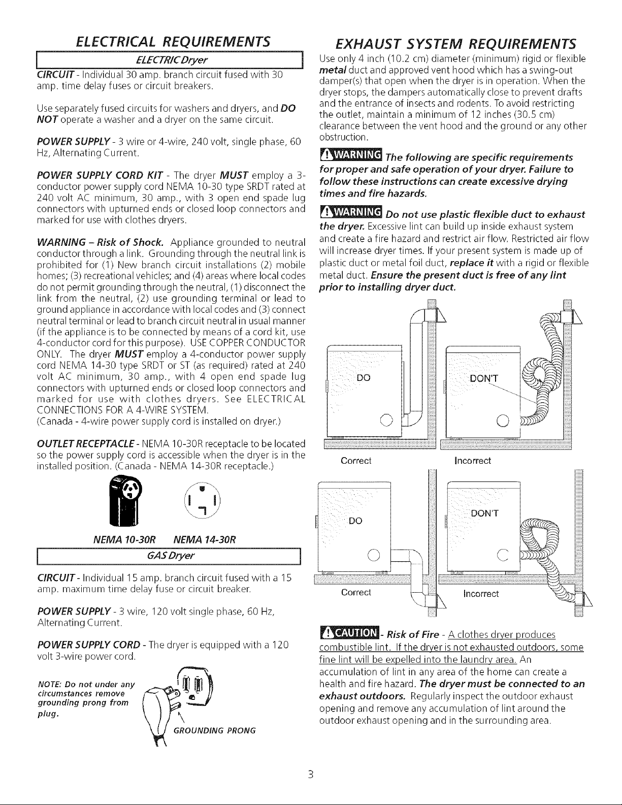
Use only 4 inch (10.2 cm) diameter (minimum) rigid or flexible
metalduct and approved vent hood which has a swing-out
damper(s) that open when the dryer is in operation. When the
dryer stops, the dampers automatically close to prevent drafts
and the entrance of insects and rodents. To avoid restricting
the outlet, maintain a minimum of 12 inches (30.5 cm)
clearance between the vent hood and the ground or any other
obstruction.
The following are specific requirements
for proper and safe operation of your dryer. Failure to
follow these instructions can create excessive drying
times and fire hazards.
Do not use plastic flexible duct to exhaust
the dryer. Excessivelint can build up inside exhaust system
and create a fire hazard and restrict air flow. Restricted air flow
will increase dryer times. If your present system is made up of
plastic duct or metal foil duct, replace it with a rigid or flexible
metal duct. Ensure the present duct is free of any lint
prior to installing dryer duct.
_i#iiiii!
i ¸¸¸¸¸¸¸¸Do
DON'T
©
OUTLET RECEPTACLE- NEMA 10-30R receptacle to be located
so the power supply cord isaccessible when the dryer is in the
installed position. (Canada - NEMA 14-30R receptacle.)
NEMA 10-30R NEMA 14-30R
GASDryer
CIRCUIT- Individual I 5 amp. branch circuit fused with a 15
amp. maximum time delay fuse or circuit breaker.
POWER SUPPLY- 3 wire, 120 volt single phase, 60 Hz,
Alternating Current.
POWER SUPPLYCORD - The dryer isequipped with a 120
volt 3-wire power cord.
f_
NOTE: Do not under any _.._ { _ _ _
circumstances remove
grounding prong from
plug.
G PRONG
Correct
DO
ii
©
Correct
_- Risk of Fire - A clothes dryer produces
combustible lint. If the dryer isnot exhausted outdoors, some
fine lint will be expelled into the laundry area. An
accumulation of lint in any area of the home can create a
health and fire hazard. The dryer must be connected to an
exhaust outdoors. Regularly inspect the outdoor exhaust
opening and remove any accumulation of lint around the
outdoor exhaust opening and in the surrounding area.
Incorrect
C
Incorrect
Do not allow combustible materials (for
example: clothing, draperies/curtains, paper) to come in
contact with exhaust system. The dryer MUST NOT be
exhausted into a chimney, a wall, a ceiling, or any concealed
space of a building which can accumulate lint, resulting in a fire
hazard.
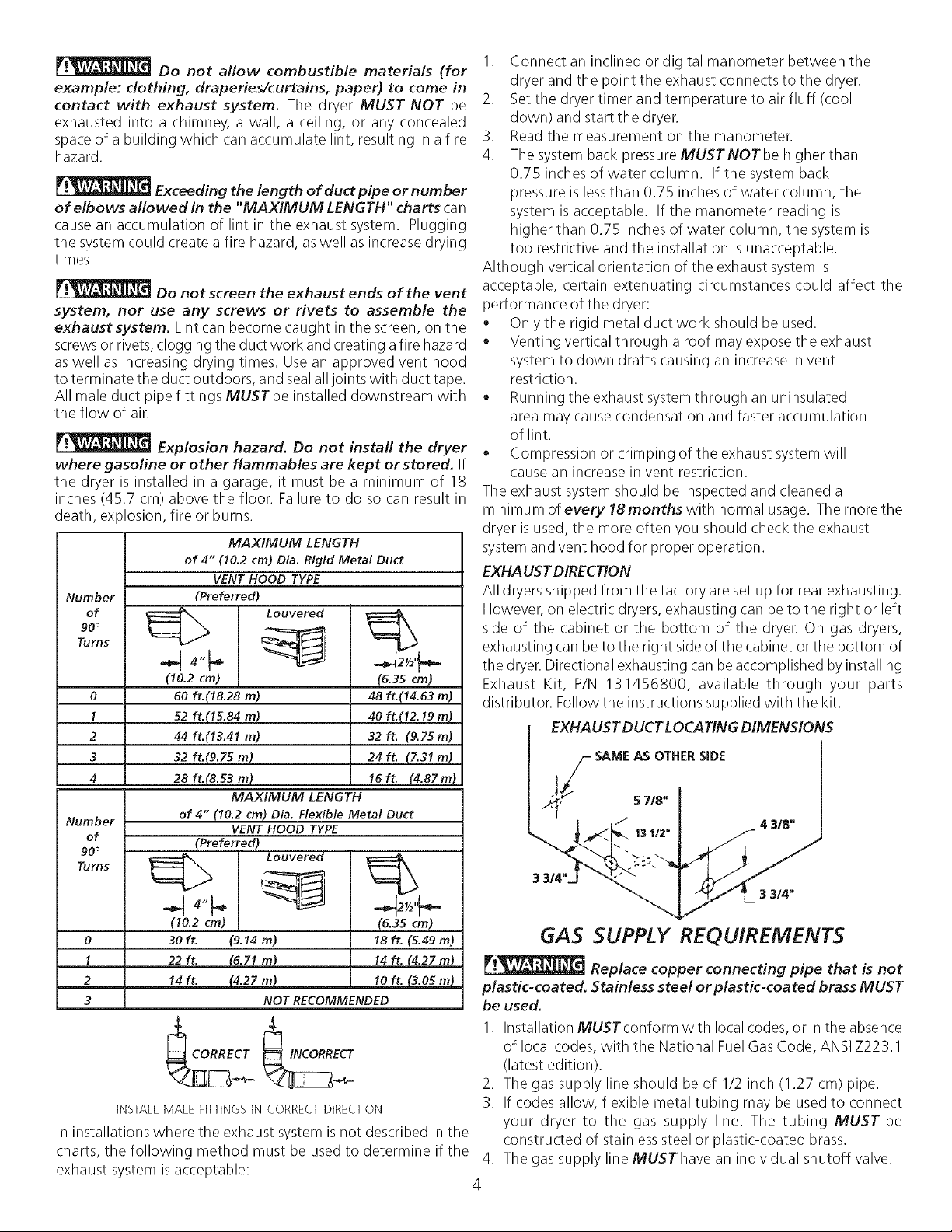
Exceeding the length of duct pipe or number
of elbows allowed in the "MAXIMUM LENGTH" charts can
cause an accumulation of lint in the exhaust system. Plugging
the system could create a fire hazard, aswell as increase drying
times.
Do not screen the exhaust ends of the vent
system, nor use any screws or rivets to assemble the
exhaust system. Lint can become caught in the screen, on the
screwsor rivets, clogging the duct work and creating afire hazard
aswell as increasing drying times. Use an approved vent hood
to terminate the duct outdoors, and sealalljoints with duct tape.
All male duct pipe fittings MUSTbe installed downstream with
the flow of air.
Explosion hazard. Do not install the dryer
where gasoline or other flammables are kept or stored. If
the dryer is installed in a garage, it must be a minimum of 18
inches (45.7 cm) above the floor. Failure to do so can result in
death, explosion, fire or burns.
MAXIMUM LENGTH
of 4" 110.2 cm) Dia. Rigid Metal Duct
VENT HOOD TYPE
Number
of
90°
Turns
0
1
2
3
4
Number
of
90°
Turns
(Preferred)
Louvered
(10.2 cm)
60 ft.(18.28 m)
52ft.(IS.84m)
44 ft.113.41 m)
32ft.(9.zsm)
28 ft.(8.53 m)
MAXIMUM LENGTH
of 4" (10.2 cm) Dia. Flexible Metal Duct
VENT HOOD TYPE
(Preferred)
48 ft.114.63 m)
40 ft.(12.19 In)
32ft. 19.75m)
24ft. {7.31m)
2 _/2'_.
(6.35 cm)
16ft. (4.87m)
I. Connect an inclined or digital manometer between the
dryer and the point the exhaust connects to the dryer.
2. Setthe dryer timer and temperature to air fluff (cool
down) and start the dryer.
3. Readthe measurement on the manometer.
4. The system back pressure MUSTNOT be higher than
0.75 inches of water column. If the system back
pressure is lessthan 0.75 inches of water column, the
system is acceptable. If the manometer reading is
higher than 0.75 inches of water column, the system is
too restrictive and the installation is unacceptable.
Although vertical orientation of the exhaust system is
acceptable, certain extenuating circumstances could affect the
performance of the dryer:
• Only the rigid metal duct work should be used.
• Venting vertical through a roof may expose the exhaust
system to down drafts causing an increase in vent
restriction.
• Running the exhaust systemthrough an uninsulated
area may cause condensation and faster accumulation
of lint.
• Compression or crimping of the exhaust system will
cause an increase in vent restriction.
The exhaust system should be inspected and cleaned a
minimum of every 18months with normal usage. The more the
dryer is used, the more often you should check the exhaust
system and vent hood for proper operation.
EXHAUST DIRECTION
All dryers shipped from the factory are set up for rear exhausting.
However, on electric dryers, exhausting can be to the right or left
side of the cabinet or the bottom of the dryer. On gas dryers,
exhausting can be to the right side of the cabinet or the bottom of
the dryer. Directional exhausting can be accomplished by installing
Exhaust Kit, P/N 131456800, available through your parts
distributor. Follow the instructions supplied with the kit.
EXHAUST DUCT LOCATING DIMENSIONS
I / SAME AS OTHER SIDE
I _'}_ ./" 5 718"
k. /_,31=j
(10.2 cm)
0
1
2
3
3Oft. (9.14 m)
22 ft. (6.71 m}
14 ft. (4.27 m)
NOT RECOMMENDED
(6.35 cm)
18 ft. (5.49 m)
14 ft. (4.27 m)
10 ft. (3.05 m)
INSTALLMALEFITTINGSINCORRECTDIRECTION
In installations where the exhaust system is not described in the
charts, the following method must be used to determine if the
exhaust system isacceptable:
GAS SUPPLY REQUIREMENTS
Replace copper connecting pipe that is not
plastic-coated. Stainless steel or plastic-coated brass MUST
be used.
I. Installation MUSTconform with local codes, or in the absence
of local codes, with the National Fuel Gas Code, ANSI Z223.1
(latest edition).
2. The gas supply line should be of 1/2 inch (1.27 cm) pipe.
3. If codes allow, flexible metal tubing may be used to connect
your dryer to the gas supply line. The tubing MUST be
constructed of stainless steel or plastic-coated brass.
4. The gas supply line MUSThave an individual shutoff valve.
4
5. A 1/8 inch (0.32 cm) N.P.T.plugged tapping, accessiblefor test gauge connection, MUST be installed immediately upstream
of the gas supply connection to the dryer.
6. The dryer MUST be disconnected from the gas supply piping system during any pressure testing of the gas supply piping system
at test pressures in excess of 1/2 psig (3.45 kPa).
7. The dryer MUST be isolated from the gas supply piping system during any pressure testing of the gas supply piping system
at test pressures equal to or lessthan
1/2 psig (3.45 kPa).
LOCATION OF YOUR DRYER
DO NOT INSTALL YOUR DRYER:
I. In an area exposed to dripping water or outside weather conditions.
2. In an area where it will come in contact with curtains, drapes, or anything that will obstruct the flow of combustion and
ventilation air.
3. On carpet. Floor MUSTbe solid with a maximum slope of I inch (2.54 cm).
INSTALLATION IN RECESSOR CLOSET
1. A dryer installed in a bedroom, bathroom, recessor closet, MUSTbe exhausted outdoors.
2. No other fuel burning appliance shall be installed in the same closet asthe Gasdryer.
3. Your dryer needs the space around it for proper ventilation.
DO NOT install your dryer in a closet with a solid door.
4. A minimum of 120 square inches (774.2 square cm) of opening, equally divided at the top and bottom of the door, is required.
Air openings are required to be unobstructed when a door is installed. A Iouvered door with equivalent air openings for the full
length of the door is acceptable.
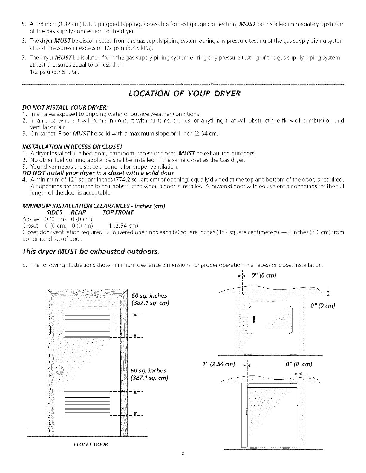
MINIMUM INSTALLATION CLEARANCES - Inches (cm)
SIDES REAR TOP FRONT
Alcove 0(0cm) 0(0cm)
Closet 0 (0 cm) 0 (0 cm) 1 (2.54 cm)
Closet door ventilation required: 2 Iouvered openings each 60 square inches (387 square centimeters) -- 3 inches (7.6 cm) from
bottom and top of door.
This dryer MUST be exhausted outdoors.
5. The following illustrations show minimum clearance dimensions for proper operation in a recessor closet installation.
II
---_ii_" (0 cm)
li
0" (Ocm)
II
1" (2.54 cm) _11 _
,, o"(o cm)
II ii
II _11 _
CLOSET DOOR
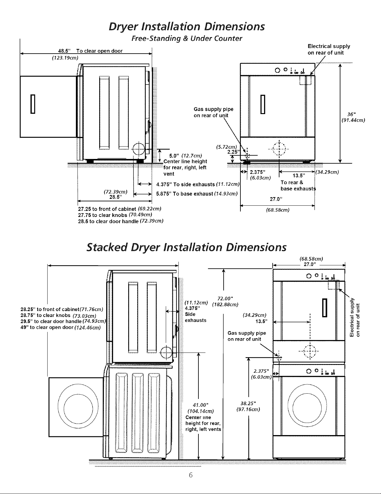
48.5"
(123.19cm)
Dryer Installation Dimensions
To clear open door
Free=Standing & Under Counter
Electrical supply
on rear of unit
/
0 o ,'_,_ #
l
27.25 to front of cabinet (69.22cm)
27.75 to clear knobs (70.49cm)
28.5 to clear door handle (72.39cm)
Stacked Dryer Installation Dimensions
1
28.25" to front of cabinet(71.76cm)
28.75" to clear knobs (73.03cm)
29.5" to clear door handle
49" to clear open door (124.46cm)
(72.39cm)
28.5"
Gas supply pipe
on rear of unit
\
(5. 72cm)
5.0" (12.7cm)
Center line height
rear, right, left ;_:!::F;;F
vent
4.375" To side exhausts (11.12cm)
5.875" To base exhaust (14.93cm)
(11.12cm) (182.88cm)
4.375"
Side
exhausts
2.25"
T
72.00"
Gas supply pipe
on rear of unit
l
_ -p
|(6.03cm) ! 13.5"
q
13.5"
(34.29cm) !
To rear &
base exhaus
27.0"
(68.58cm)
(68.58cm)
9
36"
"91.44cm)
(34.29cm)
27.0"
LU O
41.00"
(104.14cm)
Center line
height for rear,
right, left vents
6
T "_i•
38.25"
(97.16cm)
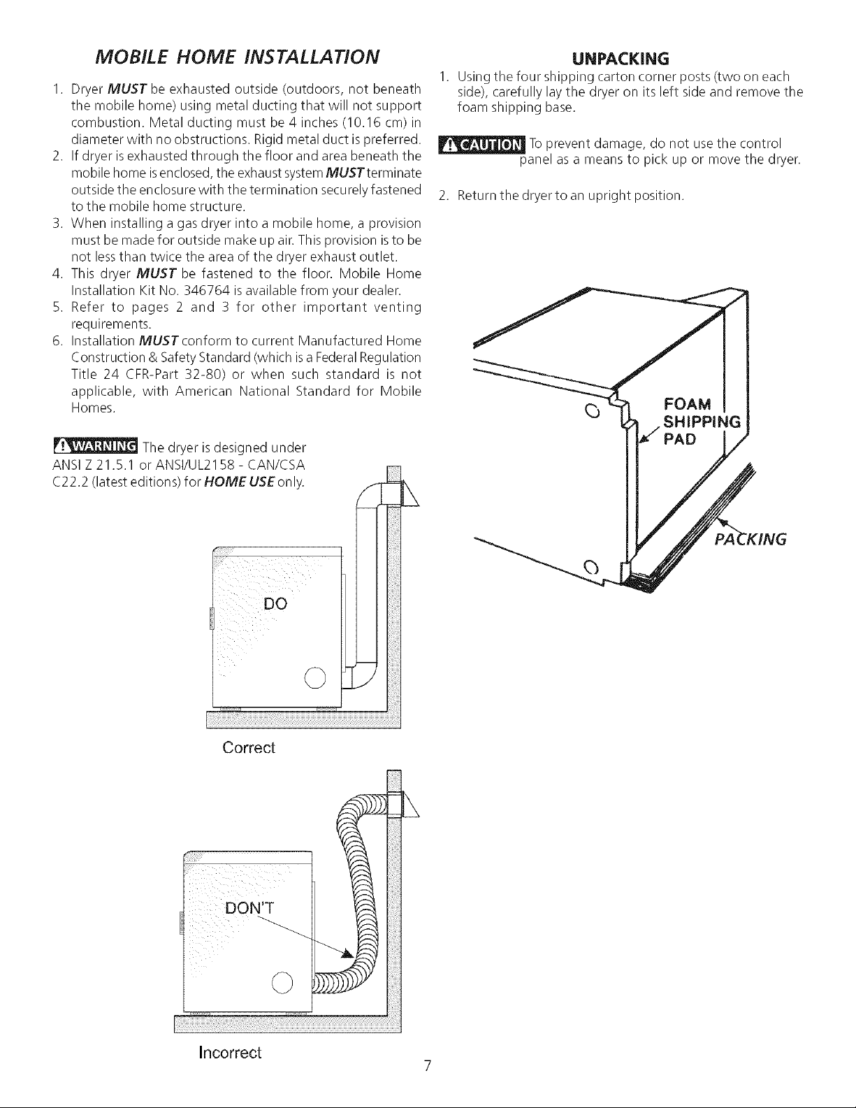
MOBILE HOME INSTALLATION
I. Dryer MUST be exhausted outside (outdoors, not beneath
the mobile home) using metal ducting that will not support
combustion. Metal ducting must be 4 inches (10.16 cm) in
diameter with no obstructions. Rigid metal duct is preferred.
2. If dryer isexhausted through the floor and area beneath the
mobile home isenclosed, the exhaust systemMUSTterminate
outside the enclosure with the termination securely fastened
to the mobile home structure.
3. When installing a gas dryer into a mobile home, a provision
must be made for outside make up air. This provision isto be
not lessthan twice the area of the dryer exhaust outlet.
4. This dryer MUST be fastened to the floor. Mobile Home
Installation Kit No. 346764 is available from your dealer.
5. Refer to pages 2 and 3 for other important venting
requirements.
6. Installation MUSTconform to current Manufactured Home
Construction & Safety Standard (which is a FederalRegulation
Title 24 CFR-Part 32-80) or when such standard is not
applicable, with American National Standard for Mobile
Homes.
The dryer is designed under
ANSI Z 21,5,1 or ANSI/UL2158- CAN/CSA
C22.2 (latest editions) for HOME USEonly.
UNPACKING
Using the four shipping carton corner posts (two on each
side), carefully lay the dryer on its left side and remove the
foam shipping base.
Toprevent damage, do not usethe control
panel as a means to pick up or move the dryer.
2. Return the dryer to an upright position.
_) FOAM
SHIPPING
PAD
Correct
i l ii
ill _ i
DO
©
!iii_iiiiiil
i_ii!iiii!i!i
Incorrect
7
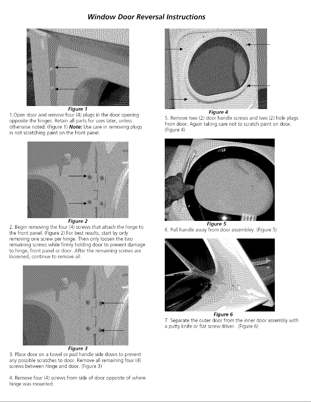
Window Door Reversal Instructions
Figure 1
1.0pen door and remove four (4) plugs in the door opening
opposite the hinges. Retain all parts for uses later, unless
otherwise noted. (Figure 1) Note: Use care in removing plugs
in not scratching paint on the front panel.
Figure 2
2. Begin removing the four (4) screws that attach the hinge to
the front panel. (Figure 2) For best results, start by only
removing one screw per hinge. Then only loosen the two
remaining screws while firmly holding door to prevent damage
to hinge, front panel or door. After the remaining screws are
loosened, continue to remove all.
Figure 4
5. Remove two (2) door handle screws and two (2) hole plugs
from door. Again taking care not to scratch paint on door.
(Figure 4)
Figure 5
6. Pull handle away from door assembley. (Figure 5)
Figure 3
3. Place door on a towel or pad handle side down to prevent
any possible scratches to door. Remove all remaining four (4)
screws between hinge and door. (Figure 3)
4. Remove four (4) screws from side of door opposite of where
hinge was mounted.
Figure 6
7. Separate the outer door from the inner door assembly with
a putty knife or flat screw driver. (Figure 6)
 Loading...