

Kenmore 41797912702, 41797912704, 41797962701, 41797962703 Installation Guide
27" (69 cm) Wide
LAUNDRY CENTER
Washer- Dryer
Installation Instructions
CENTRO DE LAVANDERiA
de 27" (69 cm) de ancho
Lavadora - Secadora
Instrucciones para la instalaci6n
J
I
i
\
Table Of Contents
S UBJECT PAGE
Pre-lnstallation Requirements ............................... 2
Electrical Requirements .......................................... 3
Water Supply Requirements .................................... 3
Drain Requirements ................................................. 3
Exhaust System Requirements ................................. 4-5
Gas Supply Requirements ........................................... 5
Location ................................................................... 5
Rough-In Dimensions ............................................. 6
Mobile Home Installation ........................................... 7
Unpacking .............................................................. 7
Electrical Installation ................................................. 8
Grounding Requirements ......................................... 8
3 & 4-Wire Connections ............................................ 9
Installation ....................................................... 10-11
Replacement Parts ................................................. 11
PIN 134809300C (0904)
Sears, Roebuck and Co., Hoffman Estates, IL 60179 U.S.A. www.sears.com
Indice
MA TERIA PA GINA
Requerimientos de instalacion preliminares .................... 12
Requerimientos electricos ........................................... 13
Requerimientos del sumin istro de agua .......................... 13
Requenmlentos de desagOe .......................................... 13
Requerimientos del sistema de escape ..................... 14-15
Requerimientos del suministro de gas............................. 15
Ubicacidn ....................................................................... 15
Dimensiones para la instalaci6n ..................................... 16
Instalaci6n en casas m6viles ........................................ 17
Desembalaje ........................................................................ 17
Instalaci6n electrica ..................................................... 18
Requerimientos para la puesta a tierra ........................... 18
Conexi6nes electricas - trifilares y tetrafilares .......... 18-19
Instalaci6n .............................................................. 19-20
Repuestos ................................................................... 20
_This isthe safety alert symbol. This symbol alerts you to hazards that can kill or hurt you or others. All safety messages will
be preceded by the safety alert symbol and the word "DANGER" or "WARNING ". Thesewords mean:
You can be killed or seriously injured if you don't immediately follow instructions.
You can be killed or seriously injured if you don't follow instructions.
All safety messages will identify the hazard, tell you how to reduce the chance of injury, and tell you what can happen if the
instructions are not followed.
Foryour safety the information in this manual must be followed to minimize the risk of fire or
explosion or to prevent property damage, personal injury or loss of life. Do not store or use gasoline or other flammable vapors
and liquid in the vicinity of this or any other appliance.
Readall of the following instructions before installing and using this appliance.
• Destroy the carton and plastic bags after the Laundry Center is unpacked. Children might use them for play. Cartons
covered with rugs, bedspreads, or plasic sheets can become airtight chambers causing suffocation. Placeall materials in a
garbage container or make materials inaccessible to children.
Installations must be performed by a qualified or licensed contractor, plumber, or gasfitter qualified or license by the state,
province, or region where this appliance is being installed.
Before beginning installation, carefully read these instructions. Thiswill simplify the installation and ensure the Laundry Center
is installed correctly and safely. Leave these instructions near the Laundry Center after installation for future reference.
The electrical serviceto the Laundry Center must conform with local codes and ordinances and the latest edition of the National
Electrical Code, ANSI/NFPA70, or in Canada, the Canadian electrical code C22.1 part 1.
The gas serviceto the Laundry Center must conform with local codes and ordinances and the latest edition of the National Fuel
GasCode ANSI Z223.1, or in Canada, CAN/ACG B149.1-2000.
The Laundry Center isdesigned under ANSI Z 21.5.1 or ANZl/UL 2158 - CAN/CSA C22.2 No. 112 (latest editions) for HOME
USEonly. This Laundry Center is not recommended for commercial applications such as restaurants or beauty salons, etc.
Do not install a Laundry Center with flexible plastic venting materials. Flexibleventing materials are known to collapse, be
easily crushed and trap lint. These conditions will obstruct clothes dryer airflow and increase the risk of fire.
Your safety and the safety of others isvery important. We have provided many important safety messages in the
Installation Instructions / Use & Care Guide and on your appliance. Always read and obey all safety messages.
The instructions in this manual and other literature included with this dryer are not meant to cover every possible condition and
situation that may occur. Good safe practice and caution MUST be applied when installing, operating and maintaing any
appliance.
WHAT TO DO IF YOU SMELL GAS
Do not try to light any appliance.
Do not touch any electrical switch; do not use any phone in your building.
Clear the room, building or area of all occupants.
Immediately call your gas supplier from a neighbor's phone. Follow the gas supplier's instructions.
If you cannot reach your gas supplier, call the fire department.
Tools and Materials Required for Installation:
Adjustable pliers.
Phillips, straight, & square bit screwdrivers.
Adjustible wrench.
Pipe wrench for gas supply (gas dryer).
LP-resistant thread tape (for natural
gas or LPsupply, gas dryer)
Carpenter's level.
External vent hood.
Rigid or semi-rigid metal 4 inch
(10.2 cm) exhaust duct work.
3-wire or 4-wire 240 volt corg kit
(electric dryer).
4 in. (10.2 cm) clamp.
Gas line shutoff valve (gas dryer).
1/2NPTunion flare adapters (x2) and
flexible gas supply line (gas dryer).
Metal foil tape not (duct tape).
[
CIRCUIT- Individual 30 amp. branch circuit fused with 30
amp. time delay fuses or circuit breakers.
Use separately fused circuits for washers and dryers, and DO
NOToperate a washer and a dryer on the same circuit.
POWER SUPPLY- 3 wire or 4-wire, 240 volt, single phase, 60
Hz, Alternating Current.
POWER SUPPLYCORD KIT- 3 wire - the dryer MUSTemploy
a 3-conductor power supply cord NEMA 10-30 type SRDTrated
at 240 volt AC minimum, 30 amp., with 3 open end spade lug
connectors with upturned ends or closed loop connectors and
marked for use with clothes dryers. See ELECTRICAL
CONNECTIONSFORA 3-WIRE SYSTEM.
4 wire - The dryer MUSTemploy a 4-conductor power supply
cord NEMA 14-30 type SRDTor ST(as required) rated at 240
volt AC minimum, 30 amp., with 4 open end spade lug
connectors with upturned ends or closed loop connectors and
marked for use with clothes dryers. See ELECTRICAL
CONNECTIONSFORA 4-WIRE SYSTEM.
(Canada - 4-wire power supply cord is installed on dryer.)
WARNING- Risk of Shock. Appliance grounded to neutral
conductor through a link. Grounding through the neutral link is
prohibited for (1) New branch circuit installations (2) mobile
homes; (3) recreational vehicles; and (4) areaswhere local codes
do not permit grounding through the neutral, (1) disconnect the
link from the neutral, (2) use grounding terminal or lead to
ground appliance in accordancewith localcodesand (3)connect
neutral terminal or lead to branch circuit neutral in usual manner
(if the appliance is to be connected by means of a cord kit, use
4-conductor cord for this purpose). USECOPPERCONDUCTOR
ONLY.
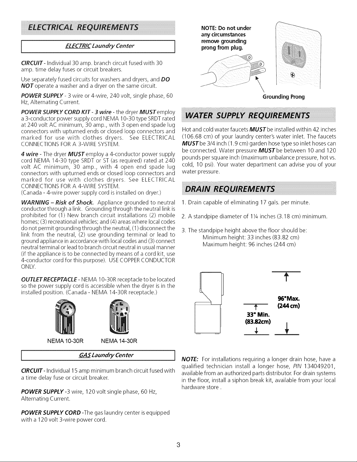
OUTLET RECEPTACLE- NEMA 10-30R receptacle to be located
so the power supply cord is accessible when the dryer is in the
installed position. (Canada - NEMA 14-30R receptacle.)
ELECTRICLaundry Center
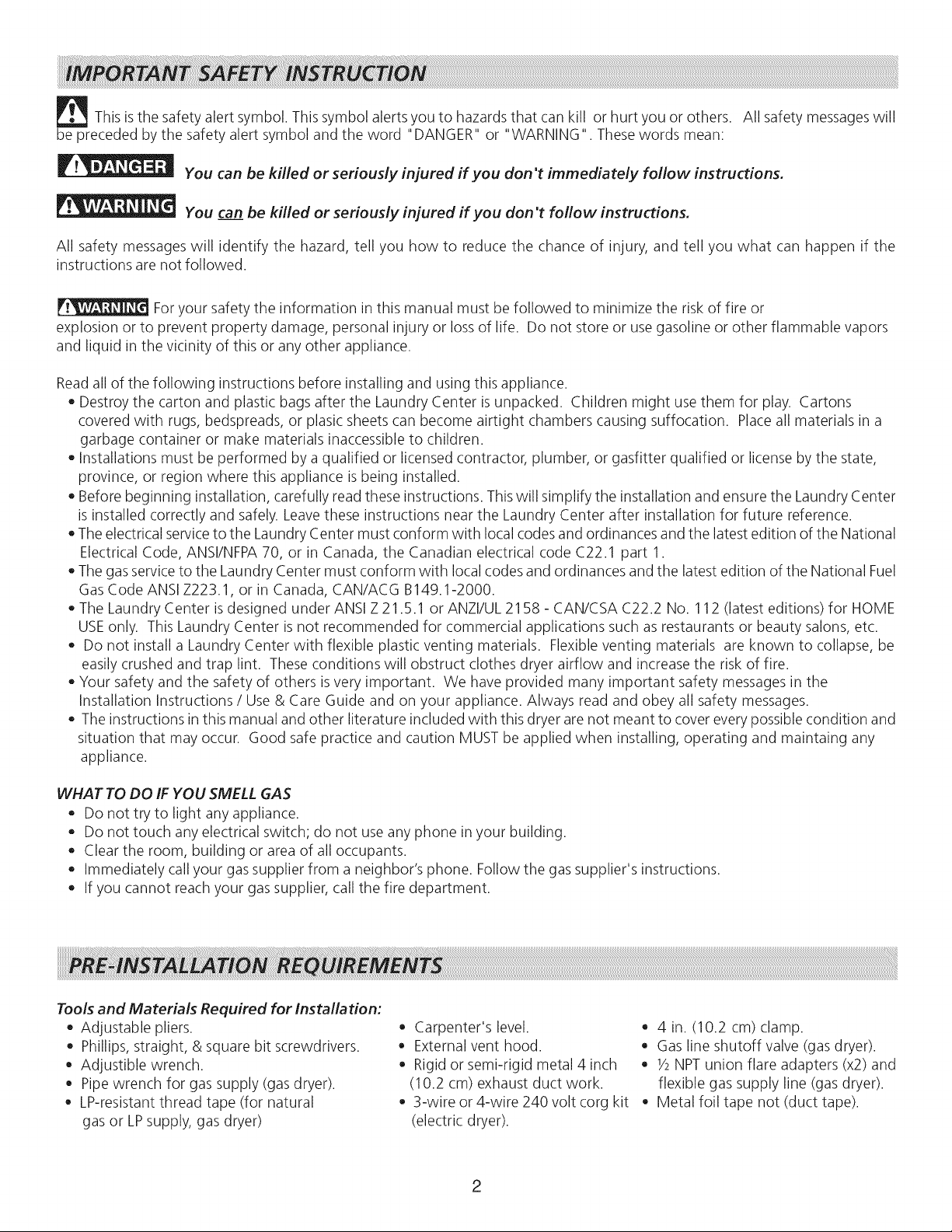
NOTE:Do not under
any circumstances
remove grounding
]
prong from plug.
\
Grounding Prong
Hot and cold water faucets MUSTbe installed within 42 inches
(106.68 cm) of your laundry center's water inlet. The faucets
MUSTbe 3/4 inch (1.9 cm) garden hose type soinlet hoses can
be connected. Water pressure MUST be between 10 and 120
pounds per square inch (maximum unbalance pressure, hot vs.
cold, 10 psi). Your water department can advise you of your
water pressure.
1. Drain capable of eliminating 17 gals. per minute.
2. A standpipe diameter of 11/4inches (3.18 cm) minimum.
3. The standpipe height above the floor should be:
Minimum height: 33 inches (83.82 cm)
Maximum height: 96 inches (244 cm)
m
f
96"Max.
? (244cm)
33" Min.
(83.82cm)
NEMA 10-30R NEMA 14-30R
[ GASLaundryCenter ]
CIRCUIT- Individual 15 amp minimum branch circuit fused with
a time delay fuse or circuit breaker.
POWER SUPPLY-3 wire, 120 volt single phase, 60 Hz,
Alternating Current.
POWER SUPPLY CORD -The gas laundry center is equipped
with a 120 volt 3-wire power cord.
NOTE: For installations requiring a longer drain hose, have a
qualified technician install a longer hose, PIN 134049201,
available from an authorized parts distributor. Fordrain systems
in the floor, install a siphon break kit, available from your local
hardware store.
3
Use only 4 inch (10.2 cm) diameter (minimum) rigid or flexible
metal duct and approved vent hood which has a swing-out
damper(s) that open when the dryer is in operation. When the
dryer stops, the dampers automatically close to prevent drafts
and the entrance of insects and rodents. Toavoid restricting the
outlet, maintain a minimum of 12 inches (30.5 cm) clearance
between the vent hood and the ground or any other obstruction.
The following are specific requirements for
proper and safe operation of your dryer. Failure to follow
these instructions can create excessive drying times and
fire hazards.
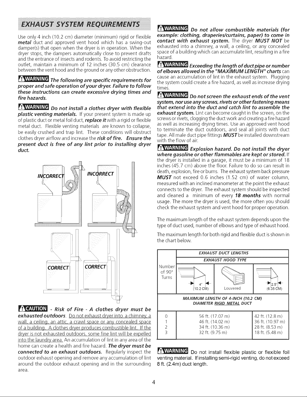
Do not install a dothes dryer with flexible
plastic venting materials. If your present system is made up
of plastic duct or metal foil duct, replace itwith a rigid or flexible
metal duct. Flexible venting materials are known to collapse,
be easily crushed and trap lint. These conditions will obstruct
clothes dryer airflow and increase the risk of fire. Ensure the
present duct is free of any lint prior to installing dryer
duct.
L
Do not allow combustible materials (for
example: dothing, draperies/curtains, paper) to come in
contact with exhaust system. The dryer MUST NOT be
exhausted into a chimney, a wall, a ceiling, or any concealed
space of a building which can accumulate lint, resulting in a fire
hazard.
Exceeding the length of duct pipe or number
of elbows allowed in the "MAXIMUM LENGTH" charts can
cause an accumulation of lint in the exhaust system. Plugging
the system could create a fire hazard, aswell as increase drying
times.
Do not screen the exhaust ends of the vent
system, nor use any screws, rivets or other fastening means
that extend into the duct and catch lint to assemble the
exhaust system. Lint can become caught in the screen, on the
screwsor rivets,clogging the duct work and creating a fire hazard
aswell as increasing drying times. Use an approved vent hood
to terminate the duct outdoors, and seal all joints with duct
tape. All male duct pipe fittings MUSTbe installed downstream
with the flow of air.
Explosion hazard. Do not install the dryer
where gasoline or other flammables are kept or stored. If
the dryer is installed in a garage, it must be a minimum of 18
inches (45.7 cm) above the floor. Failure to do so can result in
death, explosion, fire or burns. The exhaust systembackpressure
MUST not exceed 0.6 inches (1.52 cm) of water column,
measured with an inclined manometer at the point the exhaust
connects to the dryer. The exhaust system should be inspected
and cleaned a minimum of every 18 months with normal
usage. The more the dryer is used, the more often you should
check the exhaust system and vent hood for proper operation.
7
- Risk of Fire - A clothes dryer must be
exhausted outdoors. Do not exhaust dryer into a chimney, a
wall, a ceiling, an attic, a crawl space or any concealed space
of a building A clothes dryer produces combustible lint. If the
dryer is not exhausted outdoors some fine lint will be expelled
into the laundry area. An accumulation of lint in any area of the
home can create a health and fire hazard. The dryer must be
connected to an exhaust outdoors. Regularly inspect the
outdoor exhaust opening and remove any accumulation of lint
around the outdoor exhaust opening and in the surrounding
area.
The maximum length of the exhaust system depends upon the
type of duct used, number of elbows and type of exhaust hood.
The maximum length for both rigid and flexible duct is shown in
the chart below.
EXHAUST DUCT LENGTHS
EXHAUST HOOD TYPE
Number
of 90°
Turns
_ 2.5"
(10.2 CM) Louvered
MAXIMUM LENGTH OF 4-INCH (10.2 CM)
DIAMETER RIGID METAL DUCT
0
1
2
3
56 ft. (17.07 m)
46 ft. (14.02 m)
34ft. (10.36 m)
32 ft. (9.75 m)
(6_
42 ft. (12.8 m)
36 ft. (10.97 m)
28 ft. (8.53 m)
18 ft. (5.48 m)
Do not install flexible plastic or flexible foil
venting material. If installing semi-rigid venting, do not exceed
8 ft. (2.4m) duct length.
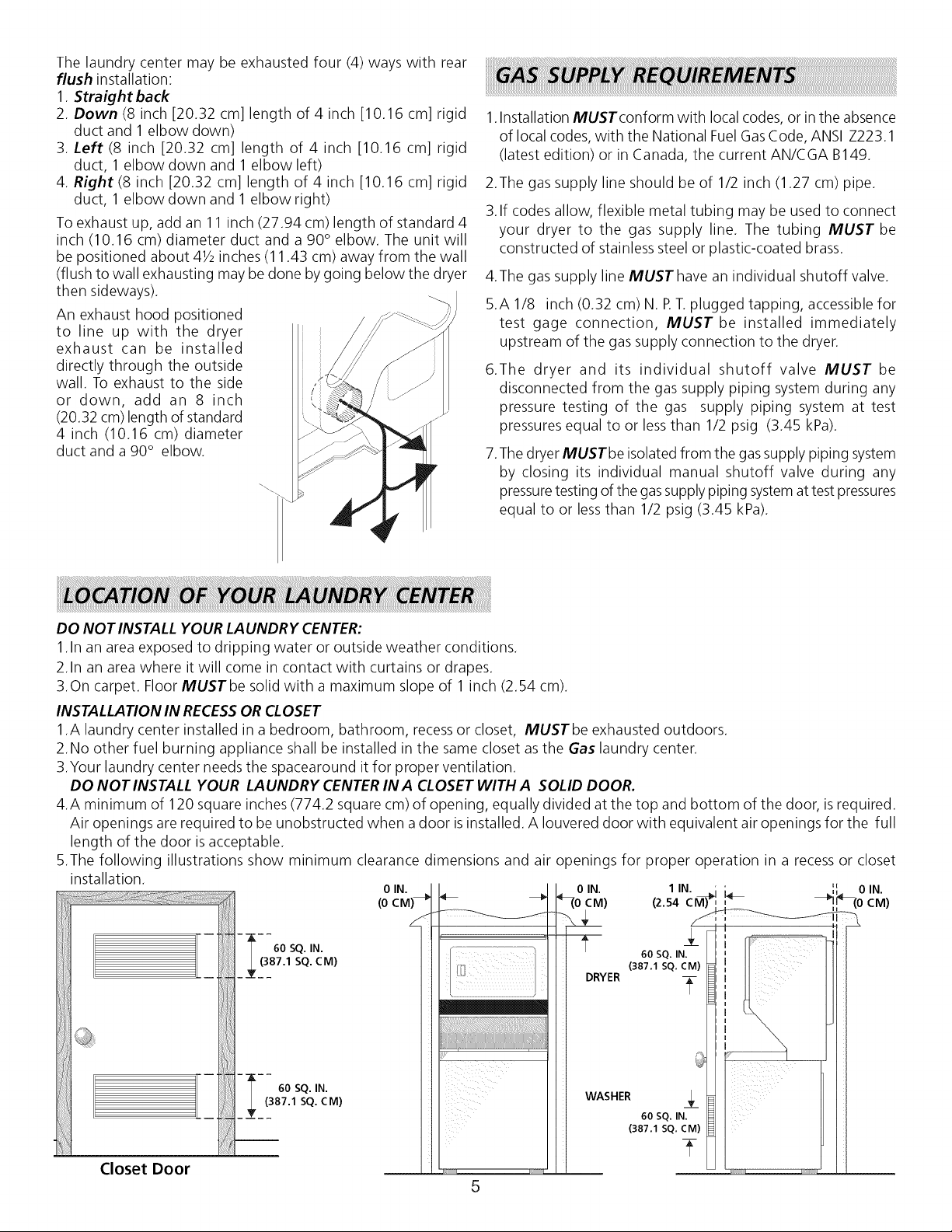
Thelaundrycentermaybeexhaustedfour(4)wayswithrear
flushinstallation:
1.Straight back
2. Down (8 inch [20.32 cm] length of 4 inch [10.16 cm] rigid
duct and 1 elbow down)
3. Left (8 inch [20.32 cm] length of 4 inch [10.16 cm] rigid
duct, 1 elbow down and 1 elbow left)
4. Right (8 inch [20.32 cm] length of 4 inch [10.16 cm] rigid
duct, 1 elbow down and 1 elbow right)
To exhaust up, add an 11 inch (27.94 cm) length of standard 4
inch (10.16 cm) diameter duct and a 90° elbow. The unit will
be positioned about 41/2inches (11.43 cm) away from the wall
(flush to wall exhausting may be done by going below the dryer
then sideways).
An exhaust hood positioned
to line up with the dryer
exhaust can be installed
directly through the outside
wall. To exhaust to the side
or down, add an 8 inch
(20.32 cm) length of standard
4 inch (10.16 cm) diameter
duct and a 90° elbow.
......
1.Installation MUST conform with local codes, or in the absence
of local codes, with the National Fuel GasCode, ANSI Z223.1
(latest edition) or in Canada, the current AN/CGA B149.
2.The gas supply line should be of 1/2 inch (1.27 cm) pipe.
3.If codes allow, flexible metal tubing may be used to connect
your dryer to the gas supply line. The tubing MUST be
constructed of stainless steel or plastic-coated brass.
4.The gas supply line MUSThave an individual shutoff valve.
5.A 1/8 inch (0.32 cm) N. F T.plugged tapping, accessible for
test gage connection, MUST be installed immediately
upstream of the gas supply connection to the dryer.
6.The dryer and its individual shutoff valve MUST be
disconnected from the gas supply piping system during any
pressure testing of the gas supply piping system at test
pressures equal to or less than 1/2 psig (3.45 kPa).
7.The dryer MUSTbe isolated from the gassupply piping system
by closing its individual manual shutoff valve during any
pressuretesting of the gas supply piping systemat test pressures
equal to or less than 1/2 psig (3.45 kPa).
DO NOT INSTALL YOUR LAUNDRY CENTER:
1.In an area exposed to dripping water or outside weather conditions.
2.In an area where it will come in contact with curtains or drapes.
3.On carpet. Floor MUSTbe solid with a maximum slope of 1 inch (2.54 cm).
INSTALLATION IN RECESSOR CLOSET
1.A laundry center installed in a bedroom, bathroom, recess or closet, MUSTbe exhausted outdoors.
2.No other fuel burning appliance shall be installed in the same closet asthe Gas laundry center.
3.Your laundry center needs the spacearound it for proper ventilation.
DO NOT INSTALL YOUR LAUNDRY CENTER IN A CLOSET WITH A SOLID DOOR.
4.A minimum of 120 square inches (774.2 square cm) of opening, equally divided at the top and bottom of the door, is required.
Air openings are required to be unobstructed when a door isinstalled. A Iouvered door with equivalent air openings for the full
length of the door is acceptable.
5.The following illustrations show minimum clearance dimensions and air openings for proper operation in a recess or closet
installation.
60 SQ.iN. 60SQ._N.
(387.1 SQ. CM) (387.1 SQ. CM) I_ II III
0 IN.
(0 _(0 c
0 IN. 1 IN. ; ; ',', 0 IN.
M) (2.54CM)'I,,_ _(0 CM)
Closet Door
(387.1 SQ. CM)
60 SQ. IN. _ I
5
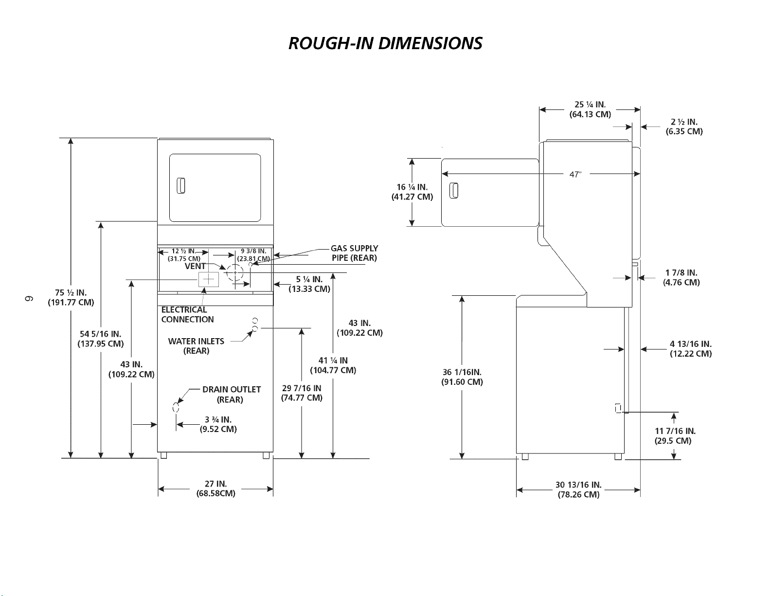
ROUGH-IN DIMENSIONS
75 1/2IN,
(191,77 CM)
54 5/16 IN,
(137.95 CM)
43 IN.
(109.22 CM)
D
II-- 121/2 IN.--]II_I _ , 93181N.
(31.75 CM) _ _1(23"81_C_
VENT_I_ _,_'_
ELECTRICAL
CONNECTION ©
WATER INLETS J_
(REAR)
_._/_ DRAIN OUTLET
<__ 3%1N,
II D
(REAR)
(9,52 CM)
_.____._ GAS SUPPLY
13.33 CM)
A (109.22 CM)
29 7/16 IN
(74.77 CM)
PIPE(REAR)
43 IN.
41 ¼ IN
(104.77 CM)
16 ¼ IN,
(41,27 CM)
U
l
36 1/161N.
(91.60CM)
II
27 IN.
(68,58CM)
30 13116 IN.
(78.26 CM)
 Loading...