

Kenmore 41747102700 Installation Guide

®
Installation
instructions
lnstrucciones
para la instalacion
Before beginning installation, carefully read these instructions. This will simplify the installation and ensure the washer is installed
correctly and safely. Leave these instructions near the washer after installation for future reference.
NOTE: The electrical service to the washer must conform with local codes and ordinances and the latest edition of the National
Electrical Code, ANSI/NFPA 70 or in Canada, CSA C22.1 Canadian Electrical Code Part 1.
Antes de comenzar la instalacion, lea estas instrucciones con atencion. Le facilitaran la instalacion y aseguraran que la lavadora sea
instalada correctamente y de manera segura. Guarde estas instrucciones cerca de la lavadora una vez terminada la instalacion para
referirse a elias en el futuro.
NO TA: el suministro el#ctrico de su lavadora debe estar conf orme con los codigos y ordenanzas Iocales y la edicion m#s reciente del
National Electrical Code (Codigo El#ctrico Nacional), ANSI/NFPA 70, o en Canada, la edicion m#s reciente del Canadian Electrical Code
(Codigo El#ctrico de Canada).
_For your safety the information inthis manual must be followed to minimize the risk of fire or explosion or to prevent
property damage, personal injury or loss of life.
Do not store or use gasoline or other flammable vapors and liquid in the vicinity of this or any other appliance.
- WHAT TO DO IF YOU SMELL GAS
• Do not try to light any appliance.
• Do not touch any electrical switch; do not use any phone in your building.
• Clear the room, building or area of all occupants.
• Immediately call your gas supplier from a neighbor's phone. Follow the gas suppliers instructions.
• If you cannot reach your gassupplier, call the fire department.
Installation and service must be performed by a qualified installer, service agency or the gas supplier.
Para su seguridad, siga la informacion contenida en este manual para minimizar el riesgo de incendio o explosion
o para evitar daflos materiales, lesiones personales o la rnuerte.
No guarde ni utilice gasolina u otros vapores y liquidos inflamables en las cercanias de este ni cualquier otro electrodomestico.
- QUEHACERSI NOTA UNOLORA GAS:
No trate de encender ningun electrodomestico.
No toque ningL]n interruptor electrico; no use ningun telefono de su edificio.
Haga que todo el mundo salga del cuarto, edificio o area.
Llame inmediatamente al proveedor del gas desde el telefono de un vecino. Siga las instrucciones del proveedor del gas.
Si no puede ponerse en contacto con el proveedor del gas, Ilame a los bomberos.
La instalacion y el servicio deben set hechos pot un instalador capacitado, una agencia de servicios o el proveedor del gas.
Save These Instructions
Sears, Roebuck and Co., Hoffman Estates, IL 60179 U.S.A.
Printed in U.S.A. P/N 134837600 (0611)
Contents
SUBJEC T PAGE
Pre-lnstallation Requirements 2
Electrical Requirements 2
Grounding Requirements 2
Water Supply Requirements 2
Drain Requirements 2
Rough-In Dimensions 3
Location Of Your Washer 3
Unpacking 3
Installation 4
Replacement Parts 4
PRE-INSTALLATION REQUIREMENTS
Tools Required for Installation:
1. 1/4 in. nut driver
2. 3/8 in. socket with ratchet.
3. 3/8 in. open end wrench.
4. 7/16 in. socket with ratchet.
5. 9/16 in. open end wrench.
6. Channel-lock adjustable pliers.
7. Carpenter's level.
ELECTRICAL REQUIREMENTS
CIRCUIT- Individual, properly polarized and grounded
15 amp. branch circuit fused with 15 amp. time delay
fuse or circuit breaker.
POWER SUPPLY- 2wire, with ground, 120 volt, single
phase, 60 Hz, Alternating Current. NOTE: The use of
this washer with power created by gas powered
generators, solar powered generators, wind powered
generators or any other generator other than the local
utility company is not recommended.
into an appropriate, copper wired receptacle that is
properly installed and grounded in accordance with
all local codes and ordinances or in the absence of
local codes, with the National ElectricalCodes, ANSI/
NFPA70 (latest edition). If in doubt, call a licensed
electrician. DO NOTcut off or alter the grounding
prong on the power supply cord. In situations where
a two-slot receptacle is present, it is the owner's
responsibility to have a licensed electrician replace
it with a properlygroundedthree prong grounding
type receptacle.
WATER SUPPLY REQUIREMENTS
Hot and cold water faucets MUST be installed within
42 inches (107 cm) of your washer's water inlet. The
faucets MUST be 3/4 inch (1.9 cm) garden hose type
so inlet hosescan be connected. Water pressure MUST
be between 10 and 120 pounds per square inch
(maximum unbalance pressure, hot vs. cold, 10 psi.)
Your water department can advise you of your water
pressure.
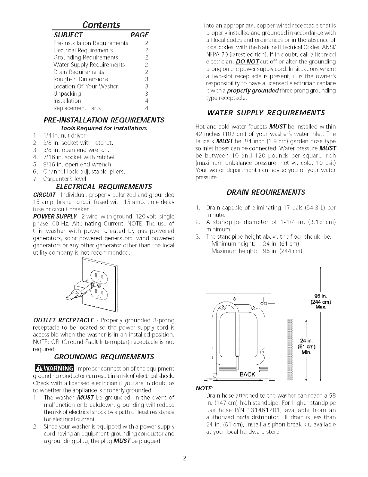
DRAIN REQUIREMENTS
1. Drain capable of eliminating 17 gals (64.3 L) per
minute.
2. A standpipe diameter of 1-1/4 in. (3.18 cm)
minimum.
3. The standpipe height above the floor should be:
Minimum height: 24 in. (61 cm)
Maximum height: 96 in. (244cm)
OUTLET RECEPTACLE- Properly grounded 3-prong
receptacle to be located so the power supply cord is
accessible when the washer is in an installed position.
NOTE: GFI (Ground Fault Interrupter) receptacle is not
required.
GROUNDING REQUIREMENTS
Improper connection of the equipment
grounding conductor can result in a riskof electricalshock,
Check with a licensed electrician if you are in doubt as
to whether the appliance isproperly grounded,
1. The washer MUST be grounded, In the event of
malfunction or breakdown, grounding will reduce
the risk of electricalshock by a path of leastresistance
for electrical current,
2. Sinceyour washer is equipped with a power supply
cord having an equipment-grounding conductor and
a grounding plug, the plug MUSTbe plugged
))
24 in.
(61 cm)
Min.
BACK
NOTE:
Drain hose attached to the washer can reach a 58
in. (147 cm) high standpipe. For higher standpipe
use hose P/N 131461201, available from an
authorized parts distributor. If drain is less than
24 in. (61 cm), install a siphon break kit, available
at your local hardware store.
96 in,
(244 cm)
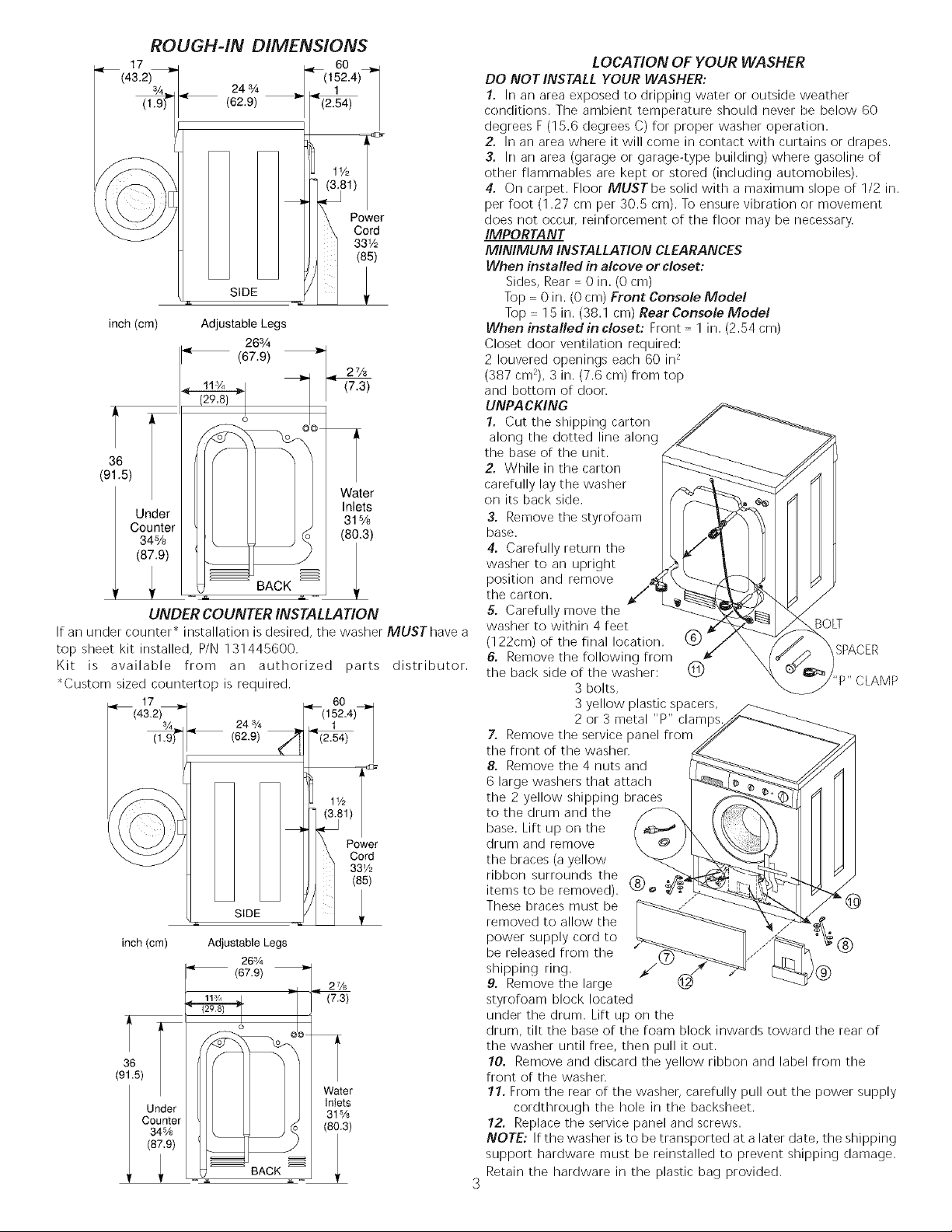
ROUGH-IN DIMENSIONS
< 17_
(43"2)3/`
3/4_,< 24 3A
(1.9) (62.9)
SIDE
inch (cm) Adjustable Legs
< (67.9)
36
(91.5)
Under 31%
Counter (80.3)
34%
(87.9) 1
! ,_ BACK ,,
26%
o
UNDER COUNTER INSTALLATION
If an under counter" installation is desired, the washer MUST have a
top sheet kit installed, P/N 131445600.
Kit is available from an authorized parts distributor.
"Custom sized countertop is required.
24s/4
(62.9)
inch (crn) Adjustable Legs
"_' (67.9)
._ _ BACK _ ._
263/4
o o @@
<60
(152.4)
(2.54)
1½
Water
2¼
(7.3)
Wate
Intet_
31sA
(8i'3
Power
Cord
331/2
(85)
2%
(7.3)
Inlets
Power
Cord
33_/2
(85)
LOCATION OF YOUR WASHER
DO NOT INSTALL YOUR WASHER:
1. In an area exposed to dripping water or outside weather
conditions. The ambient temperature should never be below 60
degrees F (15.6 degrees (3) for proper washer operation.
2. In an area where it will come in contact with curtains or drapes.
3. In an area (garage or garage-type building) where gasoline of
other flammables are kept or stored (including automobiles).
4. On carpet. Floor MUSTbe solid with a maximum slope of 1/2 in.
per foot (1.27 cm per 30.5 cm). To ensure vibration or movement
does not occur, reinforcement of the floor may be necessary.
IMPORTANT
MINIMUM INSTALLATION CLEARANCES
When installed in alcove or closet:
Sides, Rear = 0 in. (0 cm)
Top = 0 in. (0 cm) Front Console Mode!
Top = 15 in. (38.1 cm) Rear Console Model
When installed in closet: Front = 1 in. (2.54 cm)
Closet door ventilation required:
2 Iouvered openings each 60 in 2
(387 cm2), 3 in. (7.6 cm) from top
and bottom of door.
UNPA CKING
1. Cut the shipping carton
along the dotted line along
the base of the unit.
2. While in the carton
carefully lay the washer
on its back side.
3. Remove the styrofoam
base.
4. Carefully return the
washer to an upright
position and remove
the carton.
5. Carefully move the
washer to within 4 feet BOLT
(122cm) of the final location. (_)
6. Remove the following from SPACER
the back side of the washer: (_)
3 bolts,
3 yellow plastic spacers,
2 or 3 metal "P" clamps
7. Remove the service panel from
the front of the washer.
8. Remove the 4 nuts and
6 large washers that attach
the 2 yellow shipping braces
to the drum and the
base. Lift up on the
drum and remove
the braces (a yellow
ribbon surrounds the
items to be removed). (_
These braces must be (_
removed to allow the
power supply cord to
be released from the
shipping ring. )@
9. Remove the large
styrofoam block located
under the drum. Lift up on the
drum, tilt the base of the foam block inwards toward the rear of
the washer until free, then pull it out.
10. Remove and discard the yellow ribbon and label from the
front of the washer.
11. From the rear of the washer, carefully pull out the power supply
cordthrough the hole in the backsheet.
12. Replace the service panel and screws.
NOTE: If the washer is to be transported at a later date, the shipping
support hardware must be reinstalled to prevent shipping damage.
Retain the hardware in the plastic bag provided,
 Loading...