

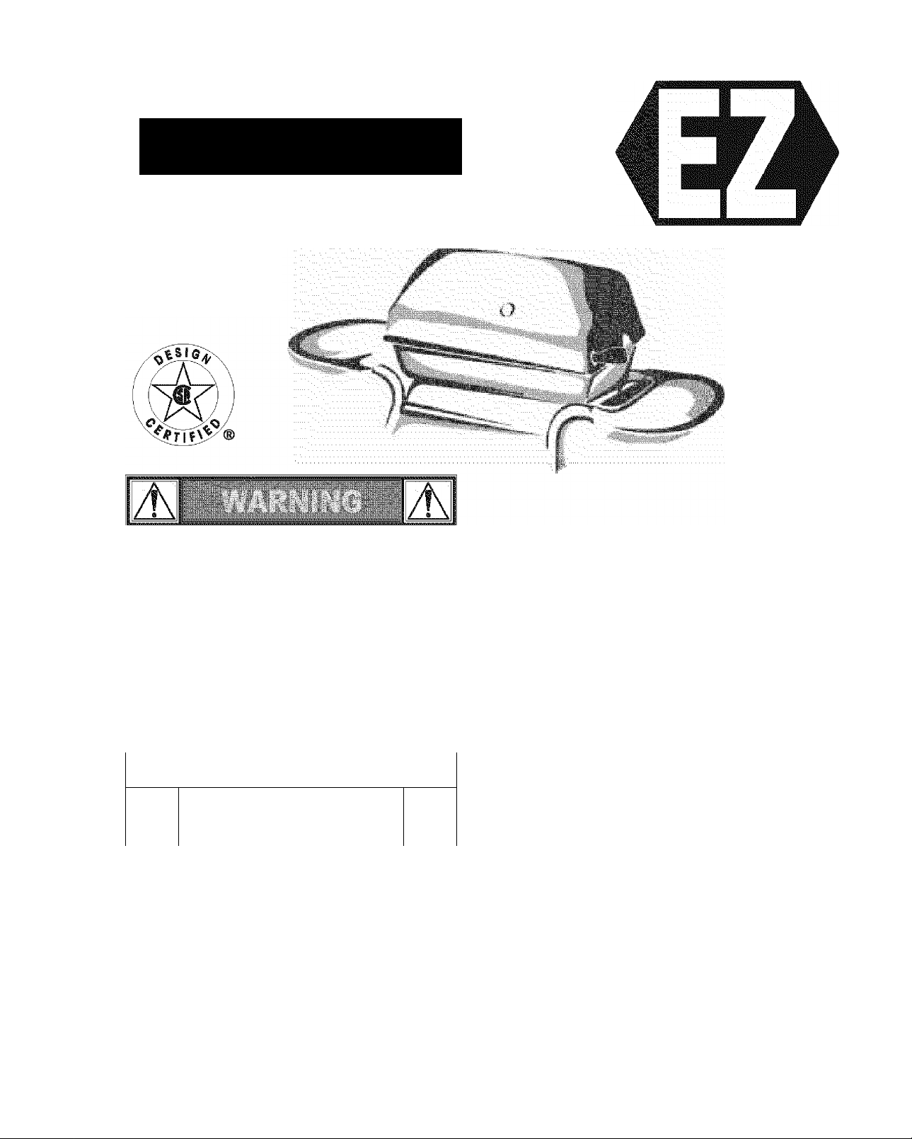
Assembly Instructions/Use and Care Manual
BÊb À
KGnmarG
Liquid Propane Gas Grili
with Grill@Night™ Night Light
Modei No. 415.162180
This Grill Is For
Outdoor Use Only
NO TOOLS
ASSEMBLY
Read this manual before cooking on
grili. Failure to foliow ali
manufacturer's instructions could
resuit in fire or explosion which could
cause property damage, personal
injury or death.
Combustion by-products produced
when using this product contain
chemicals known to the State of
California to cause cancer, birth
defects, or other reproductive harm.
..
A
Read and follow all Safety
Statements, Assembly Instructions
and Use & Care Directions before
attempting to assemble and cook.
Some parts may contain sharp edges,
especiaiiy as noted in these
instructions. Wear protective gloves
if necessary.
CAUTION
..
A
• Parts
• Assembly
• Safety Rules
Assembly Questions?
Call 1-800-4-MY-HOME®
Parts Ordering:
Call 1-800-366-PART (7278)
To Installer/Assembler: Leave
these instructions with
consumer.
To Consumer: Keep this
manual for future reference.
• Use and Care
• Troubleshooting
Sears, Roebuck and Co., Hoffman Estates, IL 60179 U.S.A.
FOR YOUR SAFETY
1. Do not store or use gasoline or other
flammable vapors and liquids in the
vicinity of this or any other appliance.
2. An LP tank not connected for use shali
not be stored in the vicinity of this or any
other appiiance.
FOR YOUR SAFETY
If you smell gas:
1. Shut off gas to the appliance.
2. Extinguish any open flame.
3. Open lid.
4. If odor continues, immediateiy call your
gas supplier or your fire department.
Safety Symbols
The symbols and boxes shown below explain what each heading
means. Read and follow all of the messages found throughout
the manual.
DANGER: Indicates an imminently hazardous situation
which, If not avoided, will result in death or serious injury.
WARNING: Be alert to the possibility of serious bodily injury
If the instructions are not followed. Be sure to read and
carefully follow all of the messages.
Call Grill Service Center For Help And Parts
If you have questions or need assistance during assembly,
please call 1-800-241-7548. You will be speaking to a
representative of the grill manufacturer and not a Sears
employee. To order new parts call Sears at 1-800-4-MY-HOME®
Product Record
IMPORT ANT; Fil l out th e pr oduc t re cord Info rmat ion
Model Number___________________________________
Serial Number
See rating label on grill for serial number.
Date Purchased.
..
/t\
CAUTION
below.
......
/K
Installation Safety Precautions
• Use grill only with LP (propane) gas and the regulator/valve
• Grill Installation must conform with local codes, or in their
• All electrical accessories (such as rôtisserie) must be
• This grill is safety certified for use in the United States only. Do
A
CAUTION: Indicates a potentially hazardous situation which,
If not avoided, may result in minor or moderate injury.
assembly supplied.
absence with National Fuel Gas Code, NFPA 54 / ANSI
Z223.1. Handling and storage of LP cylinders must conform to
LP Gas Code NFPA/ANSI58. Grill is not for use in or on
recreational vehicles and/or boats.
electrically grounded in accordance with local codes, or
National Electrical Code, ANSI / NFPA 70. Keep any
electrical cords and/or fuel supply hoses away from any hot
surfaces.
not modify for use in any other location. Modification will result
in a safety hazard.
CAUTION
A
For residential use only. Do not use for commercial
cooking.
CARBON MONOXIDE HAZARD
Burning charcoal releases carbon monoxide which has no
odor and can cause serious injury or death. Never bum
charcoal inside homes, vehicles or tents.
2•403845504

TABLE OF CONTENTS
For Your Safety..............................................................2
Gril! Service Center.......................................................2
Product Record Information.........................................2
Safety Symbols................................................................2
Installation Safety Precautions
.....................................
Kenmore Grill Wan'anty...............................................3
Parts List.........................................................................4
Parts Diagram
................................................................
Assembly....................................................................6-16
Use and Care
...........................................................
17-27
KENMORE GRILL WARRANTY
Full 1-Year Warranty on Gril!
For one year from the date of purchase Sears will repair or
replace, at our option, any grill part (except for paint finish)
2
that is defective in material or workmanship.
Limited Wamanty on Selected Gril! Parts
From one year after the date of purchase for the designated
5
time periods listed below. Sears will replace the following gril!
parts if they are defective in material or workmanship. You
will be charged for labor.
Cooking Chart.................................................25
Troubleshooting
Repair Protection Agreements
.........................................
26-27
• Lifetime of Grill: Aluminum Top and Bottom Castings
(except for paint finish)
• 9 years: Electronic Ignition System
(except for ignitor battery)
Congratulaiions on making a smart purchase. Your new
Kenmore® product is designed and manufactured for years of
dependable operation. But like all products, it may require repair
from time to time. That’s when having a Repair Protection
Agreement can save you money and aggravation.
Purchase a Repair Protection Agreement now and protect
yourself from unexpected hassle and expense.
Here’s what’s included in the Agreement:
SI Expert service by our 12,000 professional repair specialists
Unlimited service and no charge for parts and labor on all
covered repairs
Product replacement if your covered product can’t be fixed
0
Discount of 10% from regular price of service and service-
related parts not covered by the agreement; also, 10% off
regular price of preventive maintenance check
0
Fast help by phone - phone support from a Sears
technician on products requiring in-home repair, plus
convenient repair scheduling
Once you purchase the Agreement, a simple phone call is all that
it takes for you to schedule service. You can cal! anytime day or
night, or schedule a service appointment online.
Sears has over 12,000 professional repair specialists, who have
access to over 4.5 million quality parts and accessories. That’s
the kind of professionalism you can count on to help prolong the
life of your new purchase for years to come. Purchase your
Repair Protection Agreement today!
Some limitations and exclusions apply.
For prices and additional information call 1-800-827-6655.
• 2 years: Burner Assembly
WARRANTY SERVICE
Warranty service is available by contacting Sears at
1-800-4-MY-HOME®
WARRANTY RESTRICTIONS
This warranty is void if grill is used for commercial or rental
purposes.
This warranty applies only when the grill is used in the United
States.
This warranty gives you specific legal rights, and you may
also have other rights which vary from state to state.
Sears, Roebuck and Co., Dept. 817WA,
Hoffman Estates, IL 60179
Sears installation Service
For Sears professional installation of home appliances, garage
door openers, water heaters, and other major home items, in the
U.S.A. call 1-800-4-MY-HOME®
463845504 -3
PARTS LIST - Model No. 415.162180;
K6V Qis Description Part# Key Qis Description Part#
1 2
2
3
4 11 #10-24x2’ Carriage Bolt.............................. .,4080064 30 4
5
6 2 Wheei Assetmbly........................................ ,,4310002 32
7 4 1" Hitch Pin................................................. .,4080062 STD624001
8
9 1
10 1
11 1
12 1 Condiment Wire...............................
13
14 1 Burner Assembly
15
16 1 #10-16x1/2” Self-Tap Screw.......................
17 1
18 1 Control Panel..............................................
19
20 1 Valve/Hose/Regulator Assembly
21 1
22 1 Ignition Module Locking Ring
23
24 2
25
26 2 1/4-20 Wing Nut
Leg Assembly............................................. ,,4503239
1
Base
...........................................................
1
Midshelf
......................................................
12
#10-24 Plastic Tee Knob
2 Leg Extender.............................................. ,,4154577 34 1 Sideburner Body
Upper Front Panel......................................
Lower Front Panel...................................... ,,4154609
Upper Panel Wire.......................................
1 Grill Bottom................................................. ..4580540
1 Collector Box..............................................
Electrode
.........................................
4 #10x1/2", T-20, Seif-Tap Screw
Electronic Ignition Module with Wires..
2
Control Knob
Valve Clip....................................................
2 1/4-20x1-1/4" Carriage Bolt
..............................................
.................
.............................
.................
................
.....................
______
.........................................
..4502463 28
..4151035 29
..
..4080091 31
..4154428
..4156095
..........
..4151039
..
..4505078 40 1 Griii Lid..................................................... ... 4580709
,,4500278
..4080059 STD611005
..
..5156119 43
.,4526191
,,4080043
..4524194
..4153175 47 1
.,4157145
..4154559
..4151043
.....
..4080615 STD532512
..4080221 STD541625
27 2 #10-24x1-1/4” Carriage Bolt..................... ... 4080074
1
Tank Wire
...
..............................................
1
V-bar.........................................................
End Cap
...................................................
1
Side Shelf.................................................
#10-12x1-7/3” Wing Screw.......................
5
33
35
36 2 #10-24 Wing Nut
37 1
38 1
39
41 1
42 1
44 2 3/16” Pal Nut
45
46 1
48 1
49
50 1 Grease Clip
51
52 1 Ignition Button Assembly
1 Tooi Holder...............................................
......................................
1
Sideburner Frame
Sideburner
Sideburner Knob
1 Sideburner Grate
Temperature Gauge with Wing Nut ..
Temperature Gauge Bezel.......................
1
Logo Plate................................................
2 1/4x1-1/S’Hinge Pin
Griii@Night™ Handie Assembly
Lower SwingAway.................................... ...4152125
Upper SwingAway.................................... ...4156449
1 Cooking Grate.......................................... ...4152741
1
AAA Battery..............................................
....................................
......................................
...............................................
......................................
.....................................
............................................
.................................
..............................................
.........................
..............
. ..4161019
... 4500327
... 4080065
. ..4154372
...4080096
...4154376
... 4526185
... 4501705
... 4080063
... 5068026
...4154471
...4156376
...4157171
...4157169
...4156081
...4153096
...4156513
...4154619
...5156607
...4153177
...4157156
4•403845504
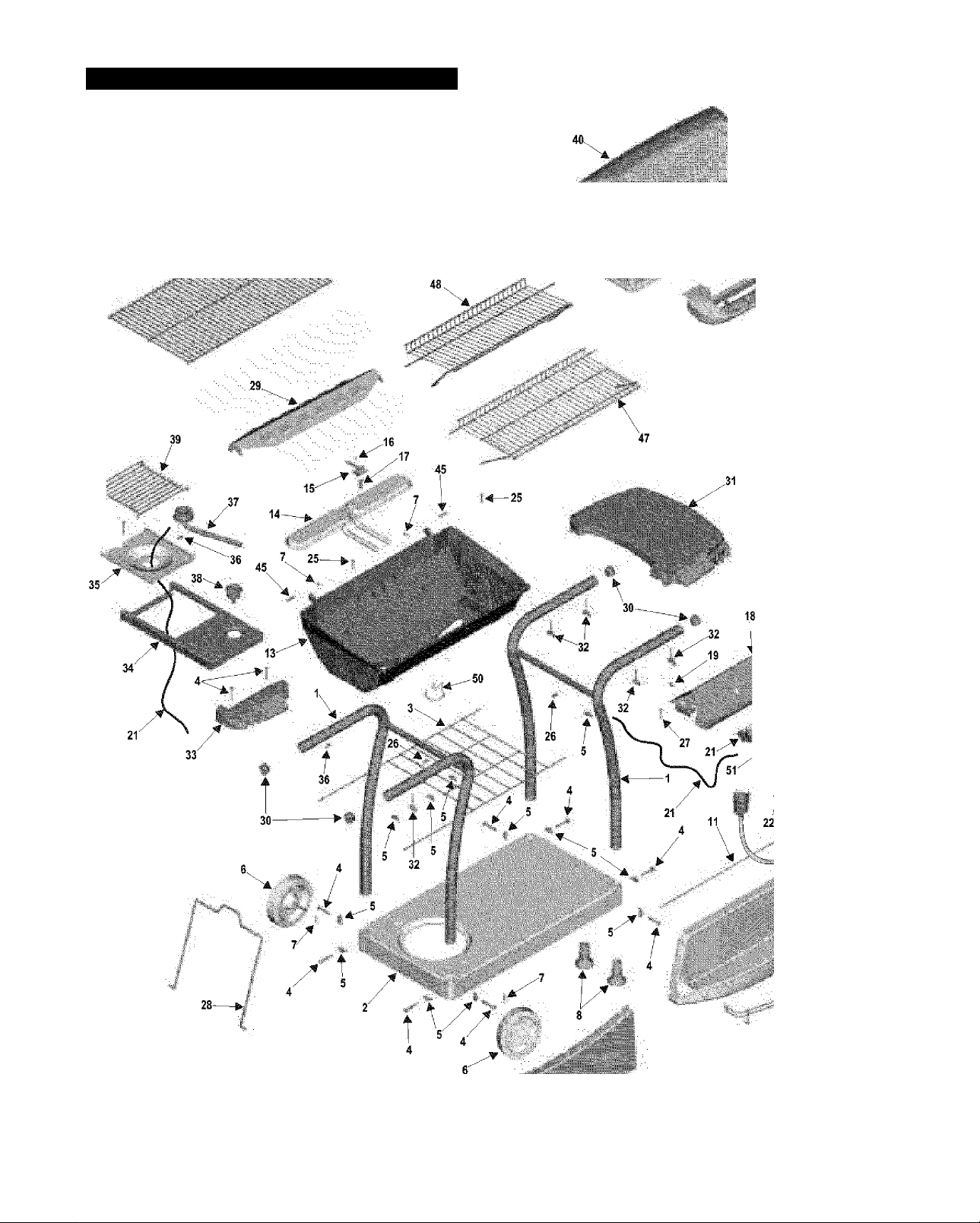
PARTS DIAGRAM - Model No. 415.162180
44
43
41
A '
4
-----
49
42
■4
46
>■
19 27
i /
1 :
■ > A-"
P'--7*' oi*-
25 T \
23
24
/20
12
10
463845504 *5
ASSEMBLY - Model No. 415.162180
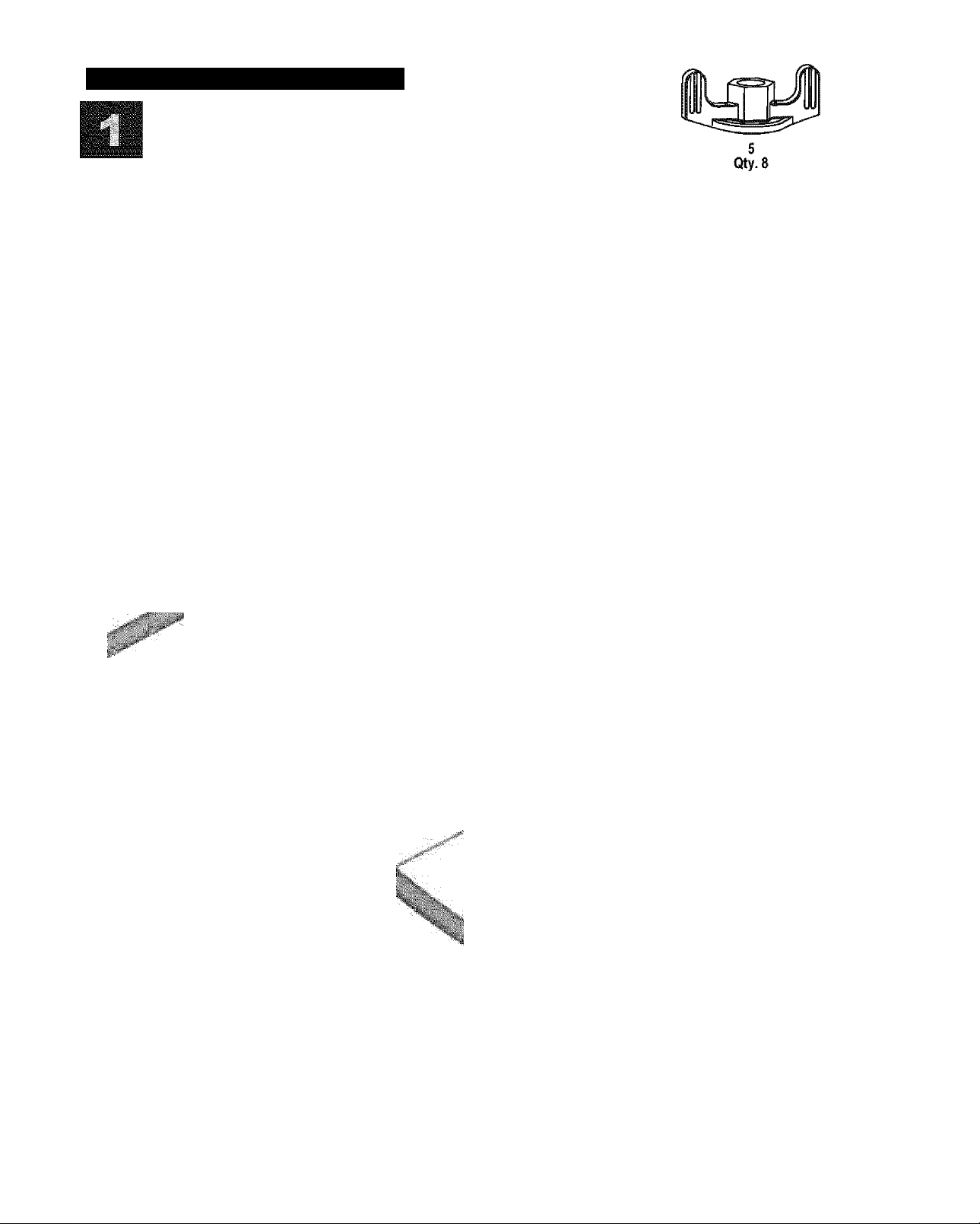
Cart Assembly Step 1
□ Position base on edge with tank hole to left side.
□ insert legs into base and attach with carriage bolts
and plastic wing nuts. Use top holes on left side.
DO NOT FULLY TIGHTEN.
□ Insert midsheif wire into holes on insides of legs,
long wires toward left side. Fully tighten carriage
bolts and plastic wing nuts.
Leg Assembly N
m
Long midshelf wire
to left side.
USE TOP HOLE-
k:
Base
6•403845504
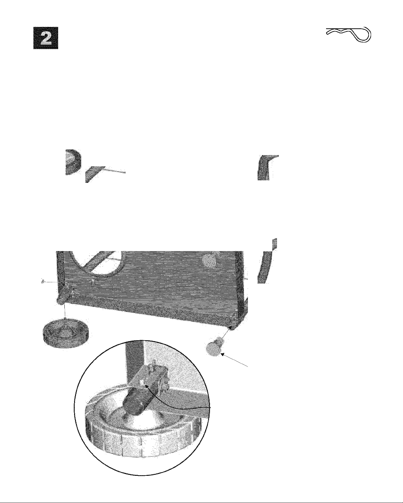
Cart Assembly Step 2
□ insert wheel/hubcap assemblies into
bottom holes on left legs.
□ Secure beneath base with hitch pins.
See inset below.
□ Push ieg extenders into right iegs.
Wheei/Hubcap Assembly
I" 1 f
■
■ i
7
Qty.2
I
I'
■
Leg Extender
Completed assembly with
hitch pin in axie bolt.
463845504 *7
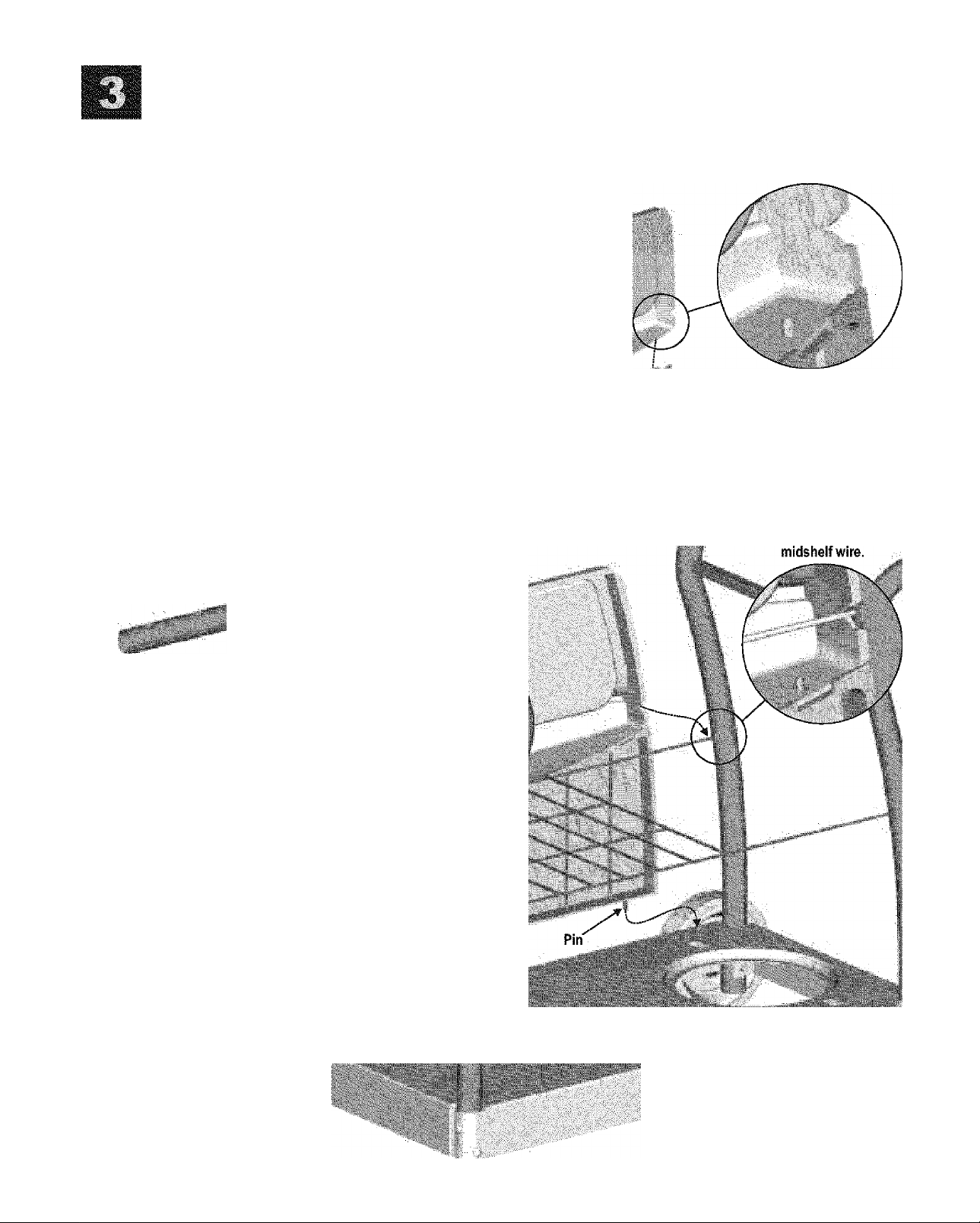
upper And Lower Front Panel Assembly
□ Snap the upper and lower front panels together.
□ insert the two pins on lower panel into holes in
front of cart base.
□ Snap the upper panel over the midshelf wire.
Upper Front Panel ■
Lower Front Pane!------------->
u
Upper panel
snaps onto
%
i
8•483845504
Pin
I
NOTE: Rear view of cart.
Wheels are to right side.
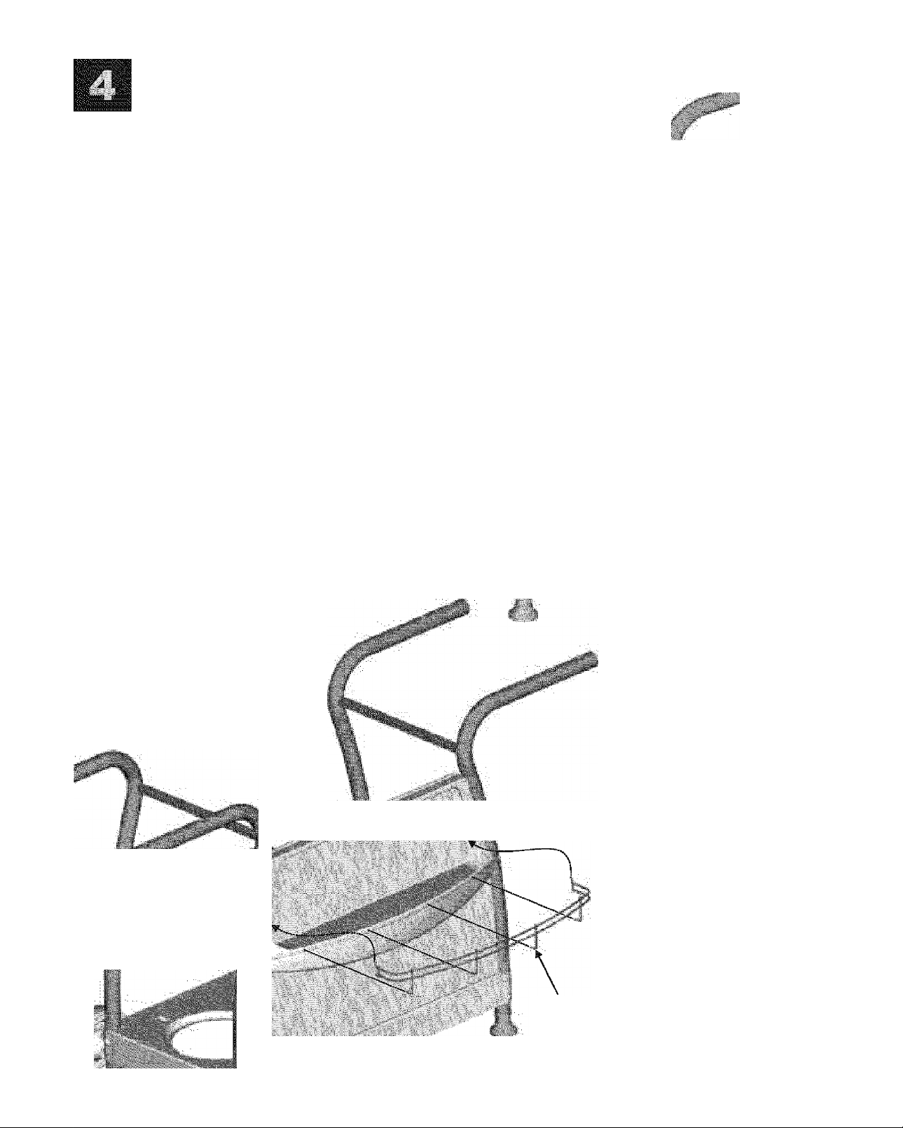
upper Panel Wire And Condiment Wire Assembly
□ insert panel wire through upper panel and into leg,
then bend wire slightly to insert opposite end.
□ Hook outer wires of condiment wire into hoies in
upper panel, rotate condiment wire down, and insert
remaining wires into holes in front of lower panel.
upper
Panel Wire
(Bend slightly
to insert)
t.:'1
■
\ ■
NOTE: Rear view of cart.
Wheels are to right side.
Condiment Wire
NOTE: front view of cart.
Wheels are to left side.
463845504 *9

Grill Bottom/Control Panel Assembly and Tank Wire
□ Carefully place grill bottom/control panel assembly onto cart, so as
not to scratch paint on legs. Make sure control panel bracket Hts over
support bar on each side.
□ insert carriage bolts through grill bottom and center hole in support
bar. Thread metal wing nuts onto bolts but do not fully tighten.
□ insert carriage bolts through control panel bracket and front holes In
support bar. Secure with plastic wing nuts.
□ Fully tighten metal wing nuts.
□ Press control knobs onto valve stems.
□ insert ends of tank wire into slots on each side of tank hole in base.
Lean tank wire toward midshelf.
25
p/n 4080615
25 27
p/n 4t)80615 p/n 4080074
Qty. 2 Qty. 2
25
p/n 4080615
Grill Bottom.'
Control Panel
Assembly
Support Bar
Center Hole
27
p/n 4080074
iW
Control
Panel
Bracket
27
p/n 4080074
Control
Knobs
Support Bar
Front Hole
r
HIIIIII&
Tank Wire
10 > 463845504
26
NOTE: Front view
of cart. Wheels are
to left side.
c
1
NOTE: Rearview
of cart. Wheeis are
to right side.

End Cap, Side Shelf, Tool Holder and V-bar Assembly
□ insert end caps into ends of leg tubes.
□ Position side shelf onto tight legs as shown
below and secure with four wing screws.
□ Position tool holder onto left front ieg and
secure with two carriage bolts and plastic
wing nuts. Use the two outer holes. Do not
use the middle hole.
□ Place V-bar into grill bottom, resting on supports
at each end.
ILiLiaJ
32
Qty.4
Side Shelf
End Cap
/
Tool-'
Holder
32
463845504*11

Sidebumer Assembly
□ Place sidebutner body onto legs. Secure at front with one wing screw through leg, tool holder, and into body.
□ insert tab on sideburner frame into hole in body. At rear leg. Insert carriage bolt through frame, body, and middle leg hole.
Secure with metal wing nut.
□ insert sideburner tube into large frame hole. Insert burner^s threaded stud into small frame hole. Attach metal wing nut to
stud, but do not fully tighten.
□ insert sideburner valve into burner tube and snap valve cup into body. Note proper tube-to-valve engagement in figure A.
Once proper engagement is made, fully tighten metal wing nut beneath burner.
□ Attach sideburner ignitor wire (long wire behind control panel) to electrode beneath sideburner. See figure B.
□ Press sideburner knob firmly onto sideburner valve and place sideburner grate onto body.
12 > 463845504

Grill Lid, Temperature Gauge and Bezel Assembly
□ Attach grill lid to grill bottom with
hinge pins and hitch pins.
□ Remove wing nut from temperature
gauge, insert gauge into bezel, then
into hole in grill lid. Secure with wing nut.
Temperature
Gauge
Grill Lid
45
p/n 4156513
i
463845504*13

Grill@N[ght™ Night Light Handie Assembiy
Note: On the underside of the iamp assembiies are “L” for ieft side and “R” for right side. Match to ietter on the handie.
□ Lamp assemblies install inside grill iid. Insert thumbscrews (provided with handle) through lamp assembiies and grill lid,
then into handie.
□ Remove the two battery door screws and install the six C-size batteries as indicated inside battery compartment.
□ Replace battery door and screws.
Note; Two extra bulbs are
contained inside the bulb
holders, attached to the
bottom of the handle.
Bulb
Holder-
.
....
.
45
Thumbscrew Left Lartip:®|f||li|W^^
Assembly
................................
- . y
"
----------------
■■■■■■
-
siPKiiia
Grill@Nighf*'
-Night Light Handle
—Bulb
Holder
CAUTION: To prevent a shorting
condition, make sure the iamp
assemblies are fully inserted into grill lid.
Screw
*
MxmsmÉ
‘V,
Screw Grill lid
14 • 463845504
Grill lid
/
Left lamp
assembly
■
Battery door
C-Size
Batteries (6)
Battery
Door
Screws

SwingAway And Cooking Grate Assembly
□ insert lower SwingAway pivot wires into bottom
holes in sides of grill lid.
□ insert lower SwingAway leg wires into top holes
In sides of grill bottom.
□ insert upper SwingAway pivot wires into middle
holes in sides of grill lid.
□ insert upper SwingAway leg wires into loops on
side of lower SwingAway.
□ Place cooking grate onto grate rests In
grill bottom.
NOTE;
Backs of SwingAways should be pointing upward.
Pivot Wire
Upper SwingAway
-m
m
o
»
Lower SwingAway
Cooking Grate
I
W:
*
m
iMi-'
fill
463845504*15

Tank Wire, LP Tank, Grease Clip and Battery
I H and ignitor Button Assembly
□ Place LP tank into hole in base with tank valve facing
toward front of grill.
□ To secure LP tank, pull tank wire over the side of the tank,
toward the tank collar.
□ See Use and Care section for connection of regulator to LP tank.
□ Hang grease clip beneath grill bottom. See inset below. To collect
grease, hang an empty soup can (not included) from grease clip.
□ Insert AAA battery (”+” end first) into ignition module, then twist
ignitor button onto module.
LP GAS TANK IS SOLD SEPARATELY. Fill and leak-check
tank before attaching to grill and regulator. See Use and
Care section for instructions.
Tank collar opening must face to front of cart once
tank is attached.
Failure to install tank correctly may allow gas hose to
be damaged in operation, resulting in the risk of fire.
r
Î
■‘i
ШШ
Tank Collar
LP Tank
(Sold
Separately)
liilte:: ’
wire
Tank Wire
ignition Module AAA Battery Ignitor Button
Rear view of grill.
Rear view of grili.
16 > 463845504
Ж
Failure to install can in clip will cause hot
grease to drip from bottom of grill with risk of
Иге or property damage.
CAUTION
A

USE AND CARE i
Never fill the cylinder beyond 80% full. An overfilled
spare LP tank is hazardous due to possible gas
released from the safety relief valve.
The safety relief valve on the LP tank could activate
releasing gas and cause an intense fire with risk of
property damage, serious injury or death.
NEVER store a spare LP tank under or near grill or in
enclosed areas.
If you see, smell or hear escaping gas, immediately get
away from the LP tank/grill and call your fire
department.
All spare LP tanks must have safety caps installed on
the LP tank outlet.
LP Tank
• The LP tank used with your grill must meet the following
requirements:
• Use LP tanks only with these required measurements: 12"
{30.5cm} (diameter) x 18" {45.7 cm) (tall) with 20 lb. (9 kg.)
capacity maximum.
• LP tanks must be constructed and marked in accordance with
specifications for LP tank of the U.S. Department of
Transportation (DOT). See LP tank collar for marking.
• LP tank valve must have:
• Type 1 outlet compatible with
regulator or grill.
• Safety relief valve. ^
• UL listed Overfill Protection
Device (OPD). This OPD safety
OPD Hand Wheel
feature is identified by a unique triangular hand wheel. Use
only LP tanks equipped with this ^pe of valve.
• LP tank must be arranged for vapor withdrawal and Include
collar to protect LP tank valve.
LP Tank Removal, Transport And Storage
LP (Liquefied Petroieum Gas)
• Turn OFF all control knobs and LP tank valve. Turn coupling
nut counterclockwise by hand only - do not use tools to
disconnect. Lift LP tank wire upward off of LP tank collar, then
lift LP tank up and off of support bracket. Install safety cap onto
LP tank valve. Always use cap and strap supplied with valve.
Failure to use safety cap as directed may result in serious
personal injui^ and/or property damage.
LP Tank Valve
• LP gas is nontoxic, odorless and colorless when produced. For
Your Safety, LP gas has been given an odor (similar to rotten
cabbage) so that It can be smelled.
• LP gas is highly flammable and may ignite unexpectedly when
mixed with air.
LPTank Filling
• Use only licensed and experienced dealers.
• LP dealer must purge tank before filling.
• Dealer should NEVER fill LP tank more than 80% of LP tank
volume. Volume of propane in tank will vary by temperature.
• A frosty regulator indicates gas overfill. Immediately close LP
tank valve and call local LP gas dealer for assistance.
• Do not release liquid propane (LP) gas into the atmosphere.
This is a hazardous practice.
• To remove gas from LP tank, contact an LP dealer or call a
local fire department for assistance. Check the telephone
directory under “Gas Companies" for nearest certified LP
dealers.
A disconnected LP tank In storage or being transported must
have a safety cap installed (as shown). Do not store an LP tank
in enclosed spaces such as a carport, garage, porch, covered
patio or other building. Never leave an LP tank inside a vehicle
which may become overheated by the sun.
Do not store an LP tank in an area where children play.
463845504*17

LP Tank Exchange
Connecting Regulator To The LP Tank
• Many retailers that sell grills offer you the option of replacing
your empty LP tank through an exchange service. Use only
those reputable exchange companies that inspect, precision fill
test and certify their cylinders. Exchange your tank only for
an OPD safety feature-equipped tank as described in the
"LP Tank" section of this manual.
• Always keep new and exchanged LP tanks in upright position
during use, transit or storage.
• Leak test new and exchanged LP tanks BEFORE
connecting to grill.
LP Tank Leak Test
For your safety
1. LP tank must be properly secured onto grill. (Refer to
assembly section.)
2. Turn all control knobs to the OFF position.
3. Turn LP tank OFF by turning OPD hand wheel clockwise to a
full stop.
4. Remove the protective cap from LP tank valve. Always use
cap and strap supplied with valve.
• Leak test must be repeated each time LP tank is exchanged or
refilled.
• Do not smoke during leak test.
• Do not use an open flame to check for gas leaks.
• Grill must be leak tested outdoors in a well-ventilated area,
away from ignition sources such as gas fired or electrical
appliances. During leak test, keep grill away from open flames
or sparks.
• Use a clean paintbrush and a 50/50 mild soap and water
solution. Brush soapy solution onto areas indicated by arrows
in figure below.
A A
If “growing” bubbles appear do not use or move the LP tank.
Contact an LP gas supplier or your fire department!
A Do not use household cleaning agents. Damage to gas
train components can result.
Do not use a POL transport plug
(piastic part with external threads)!
It will defeat the safety feature of
the valve.
5. Hold regulator and insert nipple into LP
tank valve. Hand-tighten the coupling
nut, holding regulator in a straight line
with LP tank valve so as not to cross
thread the connection.
Nipple has to be centered
Into the LP tank valve.
18 - 463845504

Leak Testing Valves, Hose and Regulator
1. Turn all grill control knobs to OFF.
2. Be sure regulator is tightly connected to LP tank.
3. Completely open LP tank valve by turning OPD hand wheel
4. Brush soapy solution onto areas where bubbles are shown in
6
. Turn the coupling nut clockwise and tighten to a full stop. The
regulator will seal on the back-check feature in the LP tank
valve, resulting in some resistance. An additional one-half to
three-quarters turn is required to complete the
connection. Tighten by hand only - do not use tools.
NOTE:
counterclockwise. If you hear a rushing sound, turn gas off
immediately. There is a major leak at the connection. Correct
before proceeding.
picture below;
▲ Never remove threaded
orifice at end of valve.
■
^ ^
If you cannot complete the connection, disconnect regulator and
repeat steps 5 and 6. If you are still unable to complete the
connection, do not use this regulator!
Do not insert any foreign objects into the valve outlet. You
may damage the valve and cause a leak. Leaking propane
may result in explosion, fire, severe personal injury, or
death.
Never attempt to attach this grill to the self-contained LP gas
system of a camper trailer or motor home.
Do not use grill until leak-tested.
If a leak is detected at any time, STOP and call the fire
department.
If you cannot stop a gas leak, immediately close LP tank
valve and call LP gas supplier or your fire department!
5. If “growing” bubbles appear, there is a leak. Close LP tank
valve immediately and retighten connections. If leaks cannot
be stopped do not try to repair. Cali Sears for replacement
parts at 1-800-4-MY-HOME®
6
. Always close LP tank valve after performing leak test by
turning hand wheel clockwise.
Sideburner
Valve
403845504-19

For Safe Use Of Your Grill And To Avoid Serious
Injury:
• Do not let children operate or play near grill.
• Keep grill area clear and free from materials that burn.
• Do not block holes In bottom or back of grill.
• Check burner flames regularly.
• Use grill only in well-ventilated space. NEVER use in
enclosed space such as carport, garage, porch, covered
patio, or under an overhead structure of any kind.
• Do not use charcoal or ceramic briquets in a gas grill.
{Unless briquets are supplied with your grill.)
• Use grill at least 3 ft. from any wail or surface. Maintain
10 ft. clearance to objects that can catch fire or sources of
ignition such as pilot lights on water heaters, live electrical
appliances, etc.
Safety Tips
A Before opening LP tank valve, check the coupling nut for
tightness.
A When grill is not in use, turn off all control knobs and LP tank
valve.
A Never move grill while in operation or still hot.
A Use long-handled barbecue utensils and oven mitts to avoid
bums and splatters.
A Maximum load for shelves is 10 lbs.
A A soup can must be attached to grease clip and emptied
after each use. Do not remove soup can until grill has
completely cooled.
A If you notice grease or other hot material dripping from grill
onto valve, hose or regulator, turn offgas supply at once.
Determine the cause, correct it, then clean and inspect valve,
hose and regulator before continuing. Perform a leak test.
A The regulator may make a humming or whistling noise during
operation. This will not affect safety or use of grill.
A If you have a grill problem see the ’Troubleshooting Section”.
If the regulator frosts, turn off grill and LP tank valve
immediately. This Indicates a problem with the tank and it
should not be used on any product. Return to supplier!
Apartment Dwellers:
Check with management to learn the requirements and fire
codes for using an LP gas grill in your apartment complex. If
allowed, use outside on the ground floor with a three {3} foot
clearance from walls or rails. Do not use on or under
balconies.
NEVER attempt to light burner with lid closed. A buildup
of non-ignited gas inside a closed grill is hazardous.
Never operate grill with LP tank out of correct position
specified in assembly instructions.
Always close LP tank valve and remove coupling nut
before moving LP tank from specified operation
position.
A
20 • 463845504

CAUTION
Match-Lighting
A Do not lean over grill while lighting.
Putting out grease fires by closing the lid is not
possible. Grills are well ventilated for safety reasons.
Do not use water on a grease fire. Personal injury may
result. If a grease fire develops, turn knobs and LP tank
off.
Do not leave grill unattended while preheating or
burning off food residue on high. If grill has not been
regularly cleaned, a grease fire can occur that may
damage the product.
Ignitor Lighting
1. Open lid. Turn on gas at LP tank.
2. Place lit match into match-lighting hole from beneath grill
bottom (as shown below).
3. Push in and turn right knob to H (ignite position). Be sure
burner lights and stays lit.
4. Light left burner by pushing left knob in and turning to 0
(ignite position).
After Lighting: Turn knobs to HI for warm-up.
A Do not lean over grill white lighting.
1. Open lid. Turn on gas at LP tank.
2. Turn left knob to @ (ignite position).
3. Push and hold ignitor button to light. Be sure burner lights and
stays lit.
4. If burner does not light, turn knobs to , wait 5 minutes,
try again.
5. Once left burner is lit, turn right knob to 0 to light right
burner.
6
. If ignitor does not work, wait 5 minutes, then follow match
lighting instructions.
After Lighting: Turn knobs to HI position for warm-up. Do not
warm up grill with knobs on # (ignite position). Knobs and
Ignitor Lighting The Sideburner
ITurn on gas at LPtank.
2. Push in and turn sideburner knob to HI.
3. Press and hold ignitor button to light. Be sure burner lights and
stays lit.
4. If burner does not light, turn sideburner knob to OFF, wait 5
minutes, try again.
Match Lighting
handle will become uncomfortably hot if left in # (ignite
position).
1. Turn on gas at LP tank.
2. Hold a lit match to any port on the sideburner. Push in and
turn the sideburner knob to Hi. Be sure burner lights and stays
CAUTION
lit.
Match-lighting hole is
beneath grill bottom.
if burner does not light, turn knobs to^B. wait 5
minutes, and try again. If the burner does not ignite with
the valve open, gas will continue to flow out of the burner
and could accidentally ignite with risk of injury.
403845504 * 21

Before Your First Cookout
Repainting Your Grill
• Light burners, check to make sure they are lit, close the lid and
warm up grill on HIGH for 15 minutes. Curing of paint and parts
will produce an odor only on first lighting.
Burner Flame Check
• Light burner, rotate knobs from HI to LO. You should see a
smaller flame in LO position than seen on HI. Always check
flame prior to each use. Perform flame check on sideburner. If
only low flame is seen refer to "Sudden drop or low flame" In
the Troubleshooting Section.
-Hi
O © O O
• After extended use and exposure to weather, paint on grill may
deteriorate or become spotted. Although this detracts from
grill's appearance, It will not impair its performance.
• To refinish your grill brush outside of grill lid and bottom with
wire brush and lightly sand with fine grit sandpaper. Sanding
allows new paint to adhere more easily. Wash grill lid and
bottom with soap and water to remove dust and grease. Do not
use a grill cleaner on outside of grill. Wipe with vinegar.
Refinish outside with heat-resistant paint. Do not paint inside
of grill.
NATURAL HAZARD • SPIDERS
Turning Grill Off
• Turn all knobs to position. Turn LP tank off by turning
OPD hand wheel clockwise to a full stop.
Ignitor Check
• Turn gas off at LP tank. Press and hold ignitor button. "Click"
should be heard and spark seen each time between collector
box or burner and electrodes. See "Troubleshooting" It no click
or spark.
FACT: Sometimes spiders and other small insects climb into
the burner tubes attached to the burners. The spiders spin
webs, build nests and lay eggs. The webs or nests can be
very small, but they are very strong and can block the flow of
gas. Clean burners prior to use after storing, at the beginning
of grilling season or after a period of one month not being
used.
CAUTION
Valve Check
• important: Make sure gas is off at LP tank before checking
valves. Knobs lock in position. To check valves, first
push in knobs and release, knobs should spring back. If knobs
do not spring back, replace valve assembly before using grill.
Turn knobs to LO position then turn back to position.
Valves should turn smoothly.
Hose Check
• Before each use, check to see if hoses are cut or worn.
Replace damaged hoses before using grill. Use only Identical
Kenmore replacement valve/hose/regulator assembly.
General Grill Cleaning
• Do not mistake brown or black accumulation of grease and
smoke for paint. Interiors of gas grills are not painted at the
factory {and should never be painted). Apply a strong solution
of detergent and water or use a grill cleaner with scrub brush
Spider guards are on the air intakes in an effort to reduce this
problem, but it will not eliminate it! An obstruction can result
In a "flashback" (a fire in the burner tubes). The grill may still
light, but the obstruction does not allow full gas flow to the
burners.
IF YOU EXPERIENCE THE FOLLOWING:
1. Smell gas.
2. Burner(s) will not light.
3. A small yellow flame from burner (should be blue).
4. Fire coming from around or behind control knob.
on insides of grill lid and bottom. Rinse and allow to completely
air dry. Do not apply a caustic grill/oven cleaner to painted
surfaces.
• Plated wire grates: Wash grates and V-bar with concentrated
grill cleaner or use soap and water solution. Dry thoroughly and
STOP!
Immediately turn off gas at LP tank!
A After a burner tube fire, you must inspect the hose and
store Indoors between cookouts.
• Plastic parts: Wash with warm soapy water and wipe dry.
A Do not use citrisol, abrasive cleaners, degreasers or a
concentrated grill cleaner on plastic parts. Damage to and
SOLUTION:
Wait for grill to cool.
failure of parts can result.
Follow the “Cleaning The Burner Assemblf Instructions.
• Porcelain grates: Because of glass-like composition, most
residue can be wiped away with baking soda/water solution or
specially formulated cleaner. Use nonabrasive scouring powder
for stubborn stains.
22 • 463845504
Clean burners often. Use a 12” pipe cleaner to clean out the
burner tubes. You may also force a stream of water from a
hose nozzle through burner tubes to clean them.
Typical spiderwebs inside burner.
do a “Leak Test” to assure no damage has occured to
the parts.

Cleaning The Burner Assembly
Follow these instructions to clean and/or replace parts of burner
assembly or If you have trouble igniting grill.
1. Turn gas off at control knobs and LP tank.
2. Remove cooking grate and V-bar.
3. Remove grease can from beneath grill. Beneath grill bottom,
disconnect ignitor wire from electrode.
4. Remove screw holding collector box. Note which hole on
collector box used for attaching to burner. Remove collector
box and clean ceramic portion of electrode with rubbing
alcohol and cloth.
5. Under control panel, disengage burner springs from burner
tubes. Do not remove springs from valves.
6. To remove burner, slide backwards, lift up and out of grill.
7. Clean outside of burner with soap and water. Lay burner
upside down on flat surface. Force a stream of water through
tubes. Make sure water comes out of all burner holes. Open
clogged holes with a thin wire. Shake out excess water and
examine holes. Due to normal wear and corrosion, some
holes may become enlarged. If any large cracks or holes are
found replace burner.
8. If grill is to be stored, coat burner lightly with cooking oil.
Wrap in protective cover to keep insects out. If not storing grill
after cleaning, hold burner at an angle and insert into grill
bottom.
9. After cleaning, insert electrode Into hole In grill bottom.
Reattach collector box to burner with screw. Be sure to use
correct hole.
10. PIace end of spring Into hole on underside of burner tube, as
before, to secure burner. See figure A.
VERY IMPORTANT: Burner tube must engage valve opening
as shown in figure A.
Screw
Collector
Box
11. Reattach Ignitor wire to electrode.
12. Reposition V-bar and cooking grate. Reattach clean can to
grease clip.
13. Before cooking again on grill, follow "Burner Flame Check".
A Do not use charcoal with this grill.
Ignitor
Wire
403845504 * 23

storing Your Grit!
• Clean cooking grates.
• Store in dry location.
• When LP tank is connected to grill, store outdoors in wellventilated space and out of reach of children.
• Cover grill if stored outdoors.
• Store grill indoors ONLY if LP tank is turned off and
disconnected, removed from grill and stored outdoors.
• When removing grill from storage follow "Cleaning Burner
Assembly" instructions before starting grill.
Direct Cooking
Use both burners to heat the grill for searing of the meat. Once
the meat has been seared, turn the burners to LO to cook meat
thoroughly.
Indirect Cooking
Once the grill is preheated, turn one of the burners off and place
your meat on the grate above the burner that is NOT burning.
This indirect method of cooking allows you to slow cook poultry
or large cuts of meat without the touch of a direct flame.
• Always cook with the iid closed.
• Due to weather conditions, cooking times may vary. During cold
and windy conditions the temperature setting may need to be
increased to insure sufficient cooking temperatures.
1. Ignite the LEFT burner. For slow cooking, adjust the control
knob to the LO setting. For faster cooking, adjust the control
knob to the H! setting.
2. Place the food on the RIGHT side of the cooking grate.
3. Because the heat source is only on one side, the food shouid
be rotated at least once during cooking to insure even
cooking. Use a meat thermometer to determine when the food
is done.
Food Safety
Food safety is a very important part of enjoying the outdoor
cooking experience. To keep food safe from harmful bacteria,
foliow these four basic steps;
Clean: Wash hands, utensils, and surfaces with hot soapy water
before and after handling raw meat and poultry.
Separate: Separate raw meats and poultry from ready-to-eat
foods to avoid cross contamination. Use a clean platter and
utensils when removing cooked foods.
Cook: Cook meat and poultry thoroughly to kill bacteria. Use a
thermometer to ensure proper internal food temperatures.
Chill: Refrigerate prepared foods and leftovers promptly.
For more information call: USDA Meat and Poultry Hotline at
1-800-535-4555 In Washington, DC (202) 720-3333,10:00 am4:00 pm EST.
How To Tell If Meat Is Grilled Thoroughly
• Meat and poultry cooked on a grill often browns very fast on the
outside. Use a meat thermometer to be sure food has reached
a safe internal temperature, and cut into food to check for
visual signs of doneness.
• Whole poultry should reach 180° F; breasts, 170° F. Juices
should run clear and flesh should not be pink.
• Hamburgers made of any ground meat or poultry should reach
160° F, and be brown in the middle with no pink juices. Beef,
veal and lamb steaks, roasts and chops can be cooked to 145°
F. Ail cuts of pork should reach 160° F.
• NEVER partially grill meat or poultry and finish cooking later.
Cook food completely to destroy harmful bacteria.
• When reheating takeout foods or fully cooked meats like hot
dogs, grill to 165° F, or until steaming hot.
24 • 463845504

Cooking Chart
Cooking times and temperatures may vary according to specific recipes, cooking conditions or barbecue equipment used. Take these
factors into consideration to insure best results. If you use the indirect cooking method (indirect cooking is lighting only one burner and
placing food on opposite side of cooking grate), allow more grilling time.
Temperatures: High = 650®F / Medium = 450°F / Low = 300°F.
Food
Beef
Setting
Hamburger 1/2” thick Medium
Steak 1/2” Medium-Hot
Roast Low
Pork
Chops 1/2”
Ribs 5-6 lbs.
Roast 3-5 lbs.
Ham Steak 1/2”
Ham 5 lb. fully cooked
Lamb
Chops 1/2”
Poultrv
Chicken 2-1/2 to 3-1/2 lbs.
Medium
Low-Medium
Low-Medium
Medium-Hot 12-15 min.
Low-Medium
Medium 6-12 min.
Low 1 hr., 15 min. to 1 hr., 30 min.
Cooking Time
Med: 7-10 min. / Well done: 10-15 min.
Rare: 3-6 min. / Med; 6-9 min. / Well done: 9-12 min.
Rare: 18-22min. per lb. / Med: 22-28 min. per lb. / Well done: 28-32 min. per lb.
Well done: 15-20 min.
Weil done: 45-90 min.
Weil done: 18-23 min. per lb.
20 min. per lb.
Chicken halved or quertered
Tuikey
Seafood
Steaks 1” thick
Fillets 6-8 oz.
Shrimp large or jumbo
Venison
Steak 1” thick
Burgers 1/2”
Roast 3-4 lbs.
Veaetables
Baking Potato whole
Onions whole
Tomatoes half
Corn whole
Low
Low-Medium
Medium-Hot
40-60 min.
18-20 min. per lb.
Well done: 10-25 min.
Medium-Hot 8-12 min.
Low-Medium 8-12 min.
Medium Rare: 8-10 min. / Med: 10-12 min.
Medium
Low-Medium
Rare: 10-12 min. 1 Med: 12-15 min.
Rare: 20-22 min. per lb. / Med: 22-25 min. per lb.
Wrap vegetables in foil
Low
Low
Medium
Low
55-60 min.
45 min.
30-40 min.
35-45 min.
Mushrooms
Medium 15-20 min.
403845504 * 25

Troubleshooting
Problem
Bumer(s) will not light
using ignitor.
Bumer(s) will not
match light.
Sudden drop in gas
flow or low flame.
Possible Cause
• Wire and/or electrode covered with
cooking residue.
• Electrode and burner are wet.
• Electrode cracked or broken "sparks at
crack"
• Wire is loose or disconnected.
• Wire is shorting (sparking) between
ignitor and electrode.
• Bad ignitor.
• No gas flow.
• Coupling nut and regulator not fully
connected.
• Obstruction of gas flow.
• Disengagement of burner to valve.
• Is grill assembled correctly?
• Out of gas.
• Excess flow valve tripped.
Prevention/Solution
• Clean wire and/or electrode with rubbing alcohol and clean swab.
• Wipe dry with cloth.
• Replace electrode.
• Reconnect wires or replace electrode/wire assembly.
• Replace ignitor wire/electrode assembly.
• Replace ignitor.
• Check to see if LP tank is emp^. If LP tank Is not empty, refer to
"Sudden drop in gas f/ow" below.
• Turn the coupling nut about one-half to three quarters additional
turn until solid stop. Tighten by hand only-do not use tools.
• Clear burner tube(s).
• Reengage burner and valve. Reattach spring clips.
• Check steps in assembly instructions.
• Check for gas in LP tank.
• Turn off knobs, wait 30 seconds and light grill. If flames are still low,
turn off knobs and LP tank valve. Disconnect regulator. Reconnect
regulator and leak test. Turn on LP tank valve, wait 30 seconds and
then light grill.
Flames blow out.
Flare-up. • Grease buildup.
Persistent grease fire
(can damage the
appearance of
aluminum castings
on the grill).
Flashback...
(fire in burner tube(s).
Unable to fill LP tank. • Some dealers have older fill nozzles
• High or gusting winds.
• Low on LP gas.
• Excess flow valve tripped.
• Excessive fat in meat.
• Excessive cooking temperature.
• Grease trapped by food buildup around
burner system.
• Burner and/or burner tubes are blocked. • Turn knobs to OFF. Clean burner and/or burner tubes.
with worn threads.
• Turn front of grill to face wind or increase flame height.
• Refill LP tank.
• Refer to "Sudden drop in gas fow" above.
• Clean grill.
• Trim fat from meat before grilling.
• Adjust (lower) temperature acx:ordingly.
• Turn knobs to OFF. Turn gas off at LP tank. Leave lid in position and
let fire burn out. After grill cools, remove, clean all parts and replace
grease can.
• The worn nozzles don't have enough "bite" to engage the valve. Try
a second LP dealer.
26 • 463845504

Troubleshooting - Electronic Ignition System
Problem
No sparks appear at
any electrodes when
ignition button is
Possible Cause
• Battery not installed • Check battery
properly. orientation.
Check Procedure
Prevention/Solution
• Install battery (make sure that “+" and ” connectors
are oriented correctly with “+” end down and ” end
up.)
pushed; no noise can
be heard from spark
module.
• Dead battery. • Has battery been
used previously?
• Replace battery with new AAA-size alkaline battery.
• Button assembly not • Check to insure • Unscrew button cap assembly and reinstall, making sure
installed properly. threads are properly
threads are aligned and engaged fully.
engaged. Button
should travel up and
down without binding.
• Faulty spark module. • If no sparks are
• Replace spark module assembly
generated with new
battery and good wire
connections, module
is faulty.
No sparks appear at • Output lead
• Are output
• Remove and reconnect all output connections at module
any electrodes when connections not connections on and and electrodes.
ignition button is
complete.
tight?
pushed; noise CAN be
heard from spark
module.
Sparks are present but
• Output lead
not at all electrodes connections not
and/or not at full
complete.
strength.
• Arcing to grill away
from burner(s).
• Weak battery. • All sparks present but
• Electrodes are wet.
• Electrodes cracked or
broken “sparks at
crack”.
• Are output • Remove and reconnect all output connections at module
connections on and
and electrodes.
tight?
• If possible, observe • If sparks are observed other than from burner(s), wire
grill in dark location.
insulation may be damaged. Replace wires.
Operate ignition
system and look for
arcing between
output wires and grill
frame.
• Replace battery with a new AAA-size alkaline battery.
weak or at slow rate.
• Has moisture
• Use paper towel to remove moisture.
aœumulated on
electrode and/or in
burner ports.
• Inspect electrodes for
• Replace cracked or broken electrodes.
cracks.
463845504 * 27

Get it fixed, at your home or ours!
Your Home
For repair-in your home-of all major brand appliances,
lawn and garden equipment, or heating and cooling systems,
no matter who made It, no matter who sold iti
For the replacement parts, accessories and
owner’s manuals that you need to do-it-yourself.
For Sears professional installation of home appliances
and items like garage door openers and water heaters.
1-800-4-MY-HOME® (1-800-469-4663)
Call anytime, day or night (U.S.A. and Canada)
www.sears.com
www.sears.ca
Our Home
For repair of carry-in items like vacuums, lawn equipment,
and electronics, call or go on-line for the location of your nearest
Sears Parts & Repair Center.
1-800-488-1222
Call anytime, day or night (U.S.A. only)
www.sears.com
To purchase a protection agreement (U.S.A.)
or maintenance agreement (Canada) on a product serviced by Sears:
1 -800-827-6655 (U S a ) 1 -800-361 -6665 (Canada)
Para pedir servicio de reparación
a domicilio, y para ordenar piezas:
1-888-SU-HOGAR^^
(1-888-784-6427)
Au Canada pour service en français:
1-800-LE-FOYER^"
(1-800-533-6937)
www.sears.ca
! Registered Trademark / ™ Trademark / Service Mark of Sears, Roebuck and Co.
! Marca Registrada / Marca de Fábrica / ™ Marca de Servicio de Sears, Roebuck and Co.
' Marque de commerce / “ Marque déposée de Sears, Roebuck and Co.
) Sears, Roebuck and Co.
 Loading...