

Kenmore 41073, 41079, 41072 Quick Start Manual
United States
INSTALLATION AND SERVICE MUST BEPERFORMED BY A QUALIRED INSTALLER.
IMPORTANT." SAVE FOR LOCAL ELECTRICAL INSPECTOR'S USE.
READ AND SAVE THESE INSTRUCTIONS FOR FUTURE REFERENCE.
FOR YOUR SAFETY: Do not store or use gasollne or other flammable
vapors and llquids in the vicinity of this or any other appllance.
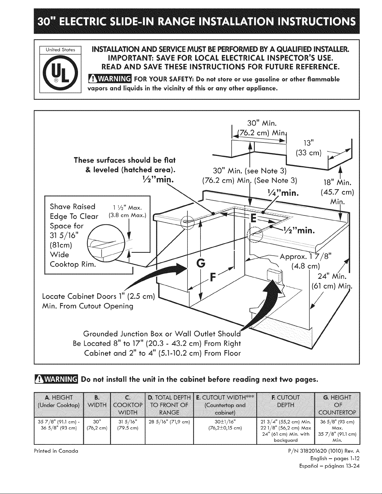
These surfaces should be fiat
& leveled (hatched area).
½"rain.
Shave Raised
Edge To Clear
Space for
31 5/16"
(81cm)
Wide
Cooktop Rim.
Locate Cabinet Doors 1" (2.5 cm)
Min. From Cutout Opening
30" Min.
_m
13" _J
30" Min. (see Note 3) _ t
(76.2 cm) Min (See Note 3) 18" Min.
G
._ 17/8"(4.8 :m)
F" : 24" Min.
(61 cm) Mir
35 7/8" (91.1 cm) -
36 5/8" (93 cm)
Printed in Canada
Grounded Junction Box or Wall Outlet
Be Located 8" to 17" (20.3 - 43.2 cm) From Right
Cabinet and 2" to 4" (5.1=10.2 cm) From Floor
Do not install the unit in the cabinet before reading next two pages.
30"
(76,2 cm)
315/16"
(79.5 cm)
28 5/16" (71,9 cm) 30_+1/16"
(76,2+0,15 cm)
21 3/4" (55,2 cm) Min.
22 1/8" (56,2 cm) Max
24" (61 cm) Min. with
backguard
P/N 318201620 (1010) Rev. A
36 5/8" (93 cm)
Max.
35 7/8" (91.1 cm)
Min.
English - pages 1-12
Espa_ol - p6ginas 13-24
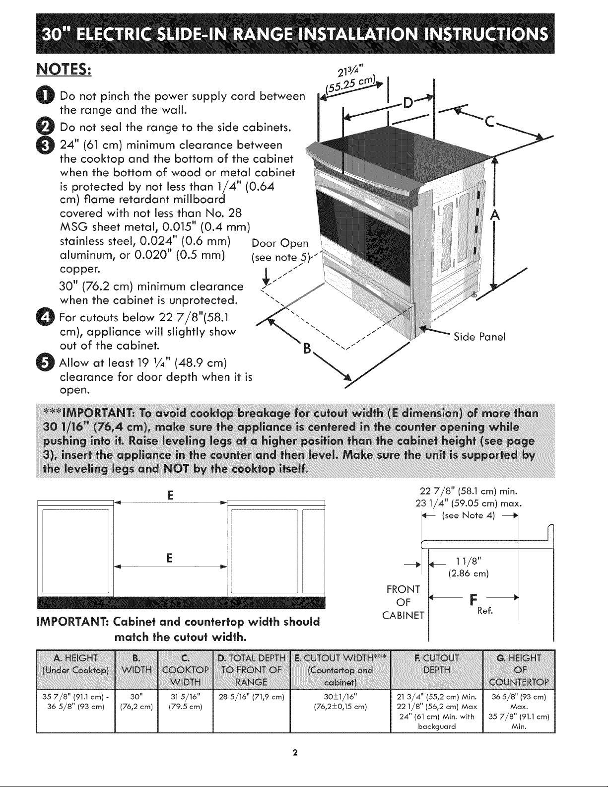
NOTES: ''
Do not pinch the power supply cord between
the range and the wall.
Do not seal the range to the side cabinets.
24" (61 cm) minimum clearance between
the cooktop and the bottom of the cabinet
when the bottom of wood or metal cabinet
is protected by not less than 1/4" (0.64
cm) flame retardant miiiboard
covered with not less than No. 28
MSG sheet metal0 0.015" (0.4 mm)
stainless steel, 0.024" (0.6 mm)
aluminum, or 0.020" (0.5 mm)
copper.
30" (76.2 cm) minimum clearance
when the cabinet is unprotected.
For cutouts below 22 7/8"(58.1
cm), appliance will slightly show
out of the cabinet.
Door Open
(see note
/
//
/"
A
Side Panel
Allow at least 19 1/4" (48.9 cm)
clearance for door depth when it is
open.
_m
E
E
_ n_lnnl_l immlilinl
IMPORTANT: Cabinet and cour|tertop width should
match the cutout width.
22 7/8" (58.1 cm) min.
23 1/4" (59.05 cm) max.
e-- (see Note 4)
/ (2.86 cm)
FRONT /
OF F
CABINET
35 7/8" (91.1 cm) -
36 5/8" (93 cm)
30"
(76,2 cm)
315/16"
(79.5 cm)
28 5/16" (71,9 cm) ao+1/16"
(76,2+0,15 cm)
21 3/4" (55,2 cm) Min.
22 1/8" (56,2 cm) Max
24" (61 cm) Min. with
backguard
36 5/8" (93 cm)
Max.
35 7/8" (91.1 cm)
Min.
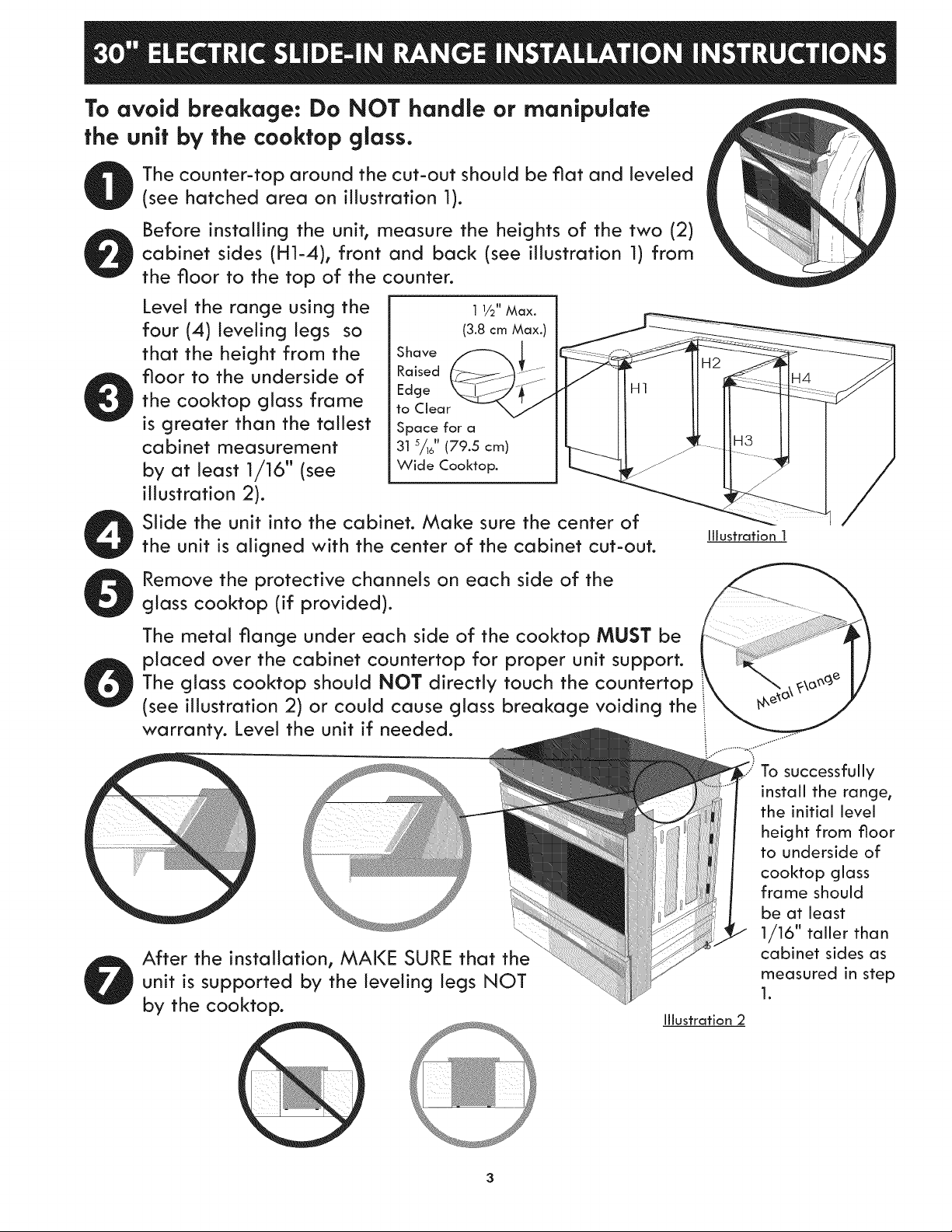
To avoid breakage: Do NOT handle or manipulate
the unit by the cooktop glass.
The counter-top around the cut-out should be fiat and leveled
(see hatched area on illustration 1).
Before installing the unit, measure the heights of the two (2)
cabinet sides (H1-4), front and back (see illustration 1) from
the floor to the top of the counter.
Level the range using the
four (4)leveling legs so
that the height from the
floor to the underside of
the cooktop glass frame
is greater than the tallest
cabinet measurement
by at least 1/16" (see
illustration 2).
Slide the unit into the cabinet. Make sure the center of
the unit is aligned with the center of the cabinet cut-out.
Iflustration I
Remove the protective channels on each side of the
glass cooktop (if provided).
The metal flange under each side of the cooktop MUST be
placed over the cabinet countertop for proper unit support.
The glass cooktop should NOT directly touch the countertop
(see illustration 2) or could cause glass breakage voiding the
warranty. Level the unit if needed.
After the installation, MAKE SURE that the
unit is supported by the leveling legs NOT
by the cooktop.
Iflustration 2
To successfully
install the range,
the initial level
height from floor
to underside of
cooktop glass
frame should
be at least
1/16" taller than
cabinet sides as
measured in step
1.
3
Important Notes to the installer
1. Read all instructions contained in these
installation instructions before installing range.
2. Remove all packing material from the oven and
the drawer compartments before connecting the
electrical supply to the range.
3. Observe all governing codes and ordinances.
4. Be sure to leave these instructions with the
consumer.
Important Note fo the Consumer
Keep these instructions with your owner's guide for
future reference.
iMPORTANT SAFETY
iNSTRUCTiONS
• Be sure your range is installed and grounded
properly by a qualified installer or service
technician.
• This range must be electrically grounded in
accordance with local codes or, in their absence,
with the Natlonal Electrical Code ANSI/NFPA
No. 70--latest edition.
• The installation of appliances designed for
manufactured (mobile) home installation must
conform with Manufactured Home Construction
and Safety Standard, title 24CFR, part 3280
[Formerly the Federal Standard for Mobile Home
Construction and Safety, title 24, HUD (part
280)] or when such standard is not applicable,
the Standard for Manufactured Home Installation
1982 (Manufactured Home Sites, Communities
and Setups), ANSI Z225.1/NFPA 501A-latest
edition, or with local codes.
• Make sure the wall coverings around the range
can withstand the heat generated by the range.
• Before installlng the range in an area covered with
linoleum or any other synthetic floor covering,
make sure the floor covering can withstand heat
° All ranges
can tip.
° Injury to
persons
could
result.
* Install
anti-tip
device
packed
with
range.
To reduce the risk of
tipping of the range, the
range must be secured by
properly installed anti-
tip bracket (s) provided
with the range. To check
if the bracket (s) is
installed properly, grasp
the top rear edge of the
range and carefully tilt it
forward to make sure the
range is anchored.
at least 90°F above room temperature without
shrinking, warping or dlscoloring.
Do not install the range over carpeting unless you
place an insulating pad or sheet of 1/4" thick
plywood between the range and carpeting.
Never leave children alone or
unattended in the area where an appliance is in
use. As children grow, teach them the proper, safe
use of att appliances. Never leave the oven door
open when the range is unattended.
Stepping, leaning or sitting on the
door or drawer of this range can result in serious
injuries and can also cause damage to the range.
* Do not store items of interest to children in the
cabinets above the range. Children could be
seriously burned climbing on the range to reach
items.
" To eliminate the risk of burns or fire by reaching
over heated surface units, cabinet storage space
above the surface unit should be avoided. If
cabinet storage is to be provided the risk can be
reduce by installing a range hood that project
horizontally a minimum of 5 inches beyond the
bottom of the cabinet.
* Do not use the oven as a storage space. This
creates a potentially hazardous situation.
* Never use your range for warming or heating
the room. Prolonged use of the range without
adequate ventilation can be dangerous.
* Do not store or use gasoline or other flammable
vapors and llquids near this or any other
appliance. Explosions or fires could resutt.
" Reset all controls to the "off" position after using
a programmable timing operation.
FOR MODELS WiTH SELF-CLEAN FEATURE:
* Remove broiler pan, food and other utenslls
before self-cieanlng the oven. Wipe up excess
spillage. Follow the pre-cleaning instructions in
the Use and Care Guide.
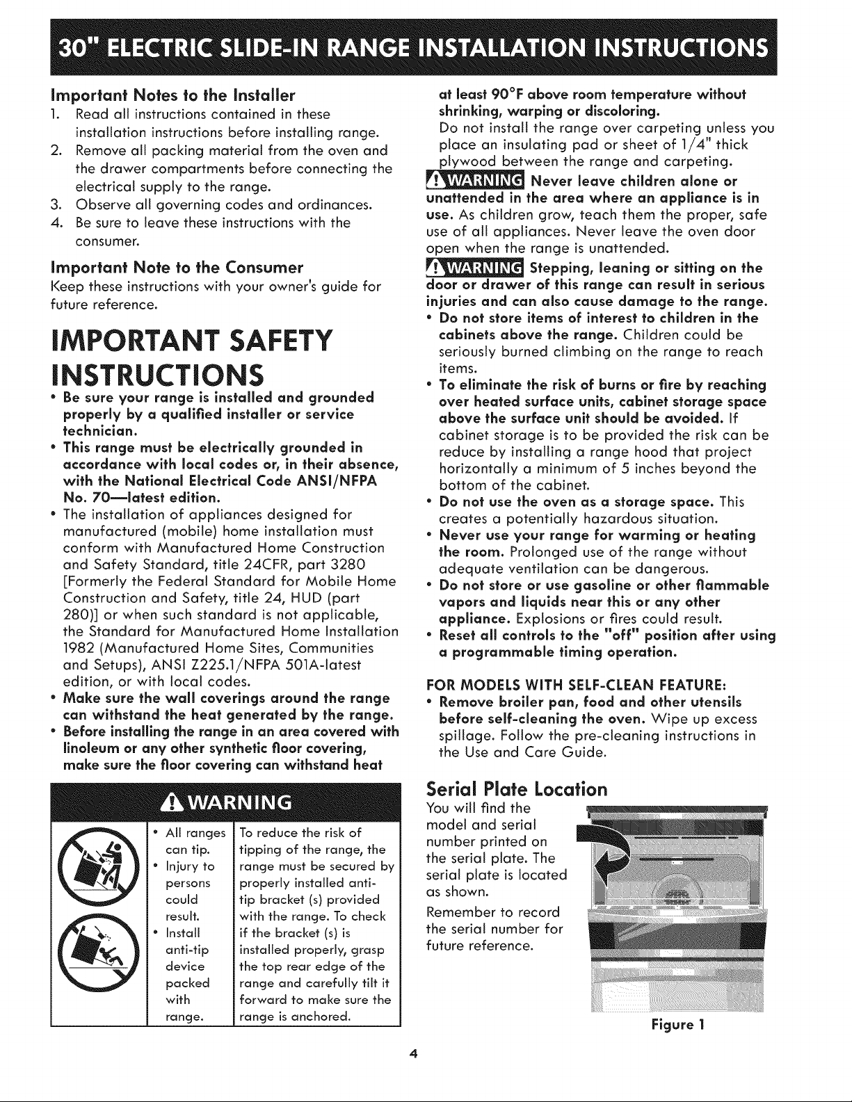
Serial Plate Location
You will find the
model and serial
number printed on
the serial plate. The
serial plate is located
as shown.
Remember to record
the serial number for
future reference.
Figure 1
Power Supply Cord Kit
The user is responsible for connecting the power
supply cord to the connection block located behind
the back panel access cover.
This appliance may be connected by means of
permanent "hard wiring"; flexible armored or
nonmetallic shielded copper cable (when local
code allow it) or by means of a power supply cord
kit.
NOTE: Electric Slide-in Range is shipped from
factory with 1 1/8" (2.9 cm) dia. hole as shown on
figure 4. If a larger hole is required, punch out the
knockout.
Risk of fire or electrical shock
exists if an incorrect size range cord kit is used,
the installation instructions are not fallowed, or
the strain relief bracket is discarded.
For mobile homes, new installations or recreational
vehicles, use only a power supply kit designed for a
range at 125V/250V 50A recommended (minimum
40A). Cord must have either 3 (when local code
permits grounding through neutral) or 4 conductors.
Terminal on end of wires must be either closed loop
or open spade tug with upturned ends. Cord must
have strain-relief clamp.
Do not loosen the nuts which secure
the factory-lnstalled range wiring to terminal
block while connecting range. Electrical failure or
loss of electrical connection may occur.
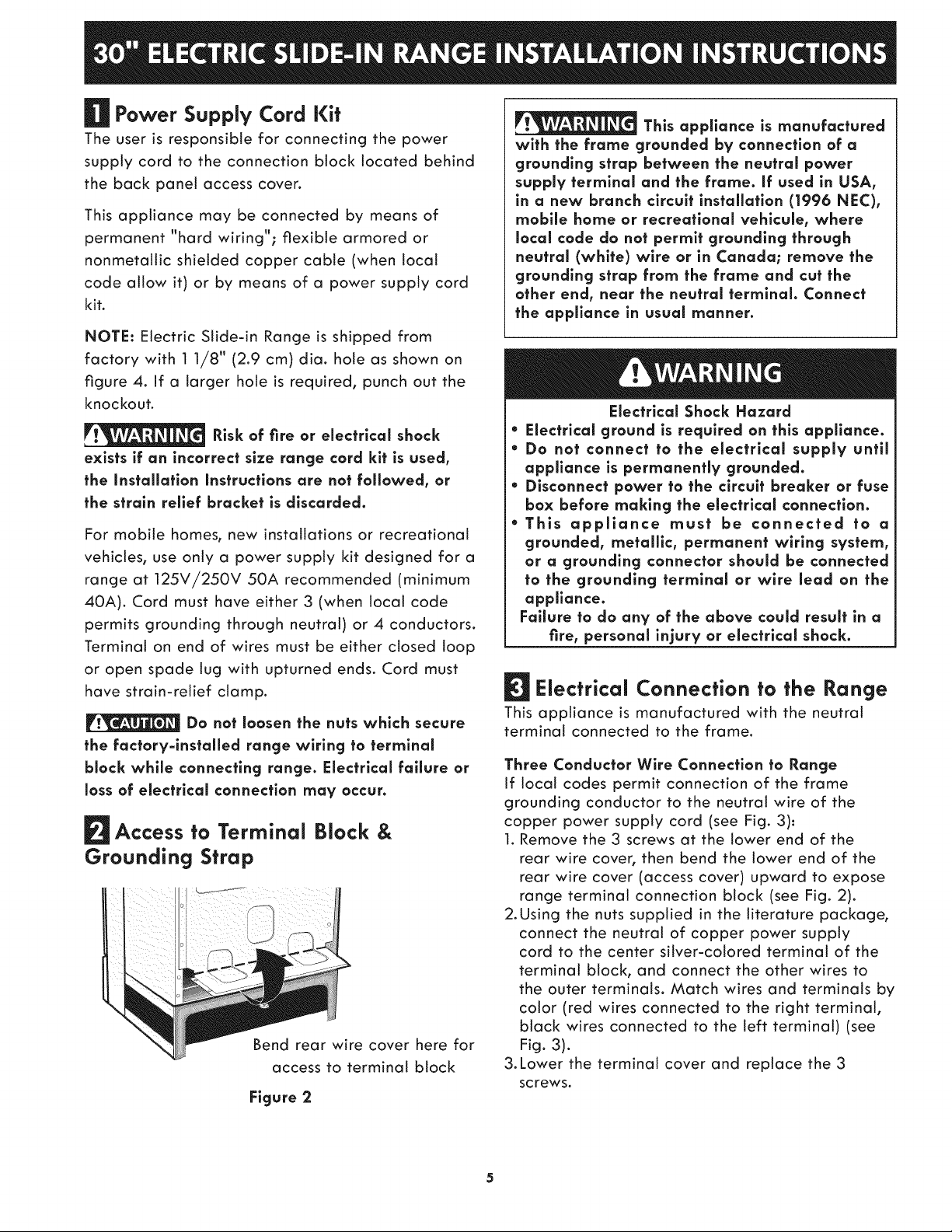
Access to Terminal Block &
Grounding Strap
Bend rear wire cover here for
access to terminal block
Figure 2
This appliance is manufactured
with the frame grounded by connection of a
grounding strap between the neutral power
supply terminal and the frame. If used in USA,
in a new branch circuit installation (1996 NEC),
mobile home or recreatlonal vehlcule, where
local code do not permit grounding through
neutral (white) wire or in Canada; remove the
grounding strap from the frame and cut the
other end, near the neutral terminal. Connect
the appliance in usual manner.
Electrical Shock Hazard
* Electrical ground is required on this appliance.
* Do not connect to the electrical supply until
appliance is permanently grounded.
* Disconnect power to the circuit breaker or fuse
box before making the electrical connection.
* This appliance must be connected to a
grounded, metallic, permanent wiring system,
or a grounding connector should be connected
to the grounding terminal or wire lead on the
appliance.
Failure to do any of the above could result in a
fire, personal injury or electrical shock.
Electrical Connection to the Range
This appliance is manufactured with the neutral
terminal connected to the frame.
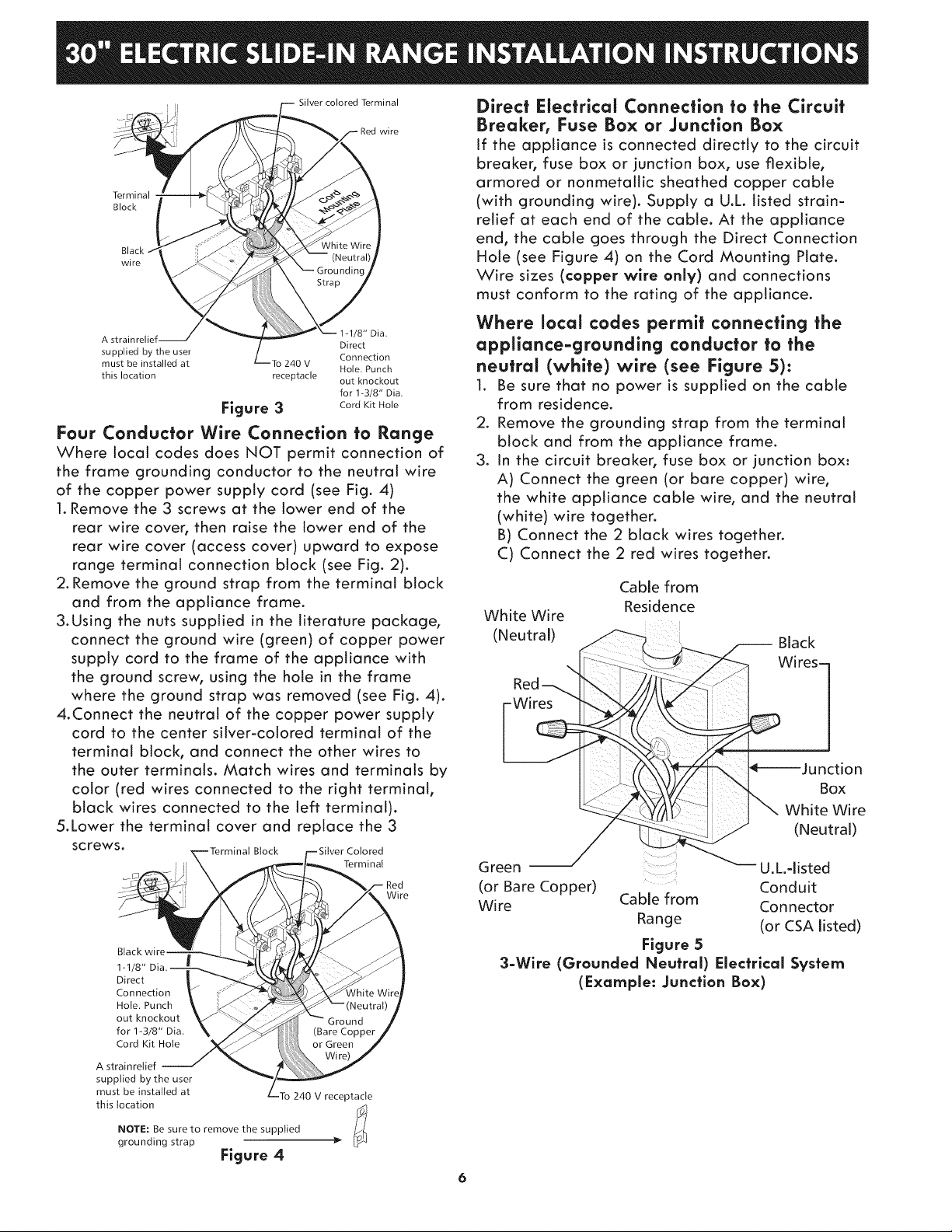
Three Conductor Wire Connection to Range
If local codes permit connection of the frame
grounding conductor to the neutral wire of the
copper power supply cord (see Fig. 3):
1. Remove the 3 screws at the lower end of the
rear wire cover, then bend the lower end of the
rear wire cover (access cover) upward to expose
range terminal connection block (see Fig. 2).
2.Using the nuts supplied in the literature package,
connect the neutral of copper power supply
cord to the center silver-colored terminal of the
terminal block, and connect the other wires to
the outer terminals. Match wires and terminals by
color (red wires connected to the right terminal,
black wires connected to the left terminal) (see
Fig. 3).
&Lower the terminal cover and replace the 3
screws.
Terminal
Block
wire
Silver colored Terminal
wi re
Direct Electrical Connection to the Circuit
Breaker, Fuse Box or Junction Box
If the appliance is connected directly to the circuit
breaker, fuse box or junction box, use flexible,
armored or nonmetallic sheathed copper cable
(with grounding wire). Supply a U.L listed strain-
relief at each end of the cable. At the appliance
end, the cable goes through the Direct Connection
Hole (see Figure 4) on the Cord Mounting Plate.
Wire sizes (copper wire only) and connections
must conform to the rating of the appliance.
A strainrelief-- Direct
supplied by the user Connection
must be installed at To 240 V
this location receptacle out knockout
1-1/8" Dia.
Hole. Punch
for 1-3/8" Dia.
Figure 3 CordKitHole
Four Conductor Wire Connection to Range
Where local codes does NOT permit connection of
the frame grounding conductor to the neutral wire
of the copper power supply cord (see Fig. 4)
1.Remove the 3 screws at the lower end of the
rear wire cover, then raise the lower end of the
rear wire cover (access cover) upward to expose
range terminal connection block (see Fig. 2).
2. Remove the ground strap from the terminal block
and from the appliance frame.
&Using the nuts supplied in the literature package,
connect the ground wire (green) of copper power
supply cord to the frame of the appliance with
the ground screw, using the hole in the frame
where the ground strap was removed (see Fig. 4).
4.Connect the neutral of the copper power supply
cord to the center silver-colored terminal of the
terminal block, and connect the other wires to
the outer terminals. Match wires and terminals by
color (red wires connected to the right terminal,
black wires connected to the left terminal).
5.Lower the terminal cover and replace the 3
screws. Block Colored
i Terminal
Wire
1-1/8"
Direct
Connection
Hole. Punch
out knockout
for 1-3/8" Dia.
Cord Kit Hole
A strainreiief
supplied by the user
must be installed at
this location
NOTE: Be sure to remove the supplied
grounding strap
240 V receptacle
Figure 4
Where local codes permit connecting the
appliance-grounding conductor to the
neutral (white) wire (see Figure 5):
1. Be sure that no power is supplied on the cable
from residence.
2. Remove the grounding strap from the terminal
block and from the appliance frame.
3. In the circuit breaker, fuse box or junction box:
A) Connect the green (or bare copper) wire,
the white appliance cable wire, and the neutral
(white) wire together.
B) Connect the 2 black wires together.
C) Connect the 2 red wires together.
Cable from
White Wire
(Neutral)
Green .... U.L.qisted
(or Bare Copper) Conduit
Wire Cable from Connector
3-Wire (Grounded Neutral) Electrical System
Residence
Black
Wires-
Box
White Wire
(Neutral)
Range (or CSA listed)
Figure 5
(Example: Junction Box)
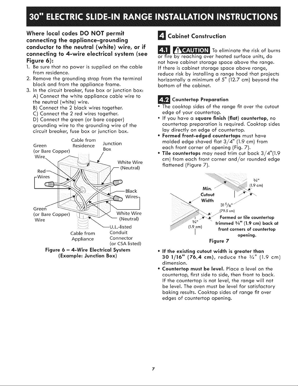
Where local codes DO NOT permit
connecting the appliance-grounding
conductor to the neutral (white) wire, or if
connecting to 4-wire electrical system (see
Figure 6):
1. Be sure that no power is supplied on the cable
from residence.
2. Remove the grounding strap from the terminal
block and from the appliance frame.
3. in the circuit breaker, fuse box or junction box:
A) Connect the white appliance cable wire to
the neutral (white) wire.
B) Connect the 2 black wires together.
C) Connect the 2 red wires together.
D) Connect the green (or bare copper)
grounding wire to the grounding wire of the
circuit breaker, fuse box or junction box.
Cable from
Green
(or Bare Copper)
Wire
Residence Junction
Box
White Wire
(Neutral)
Cabinet Construction
To eliminate the risk of burns
or fire by reaching over heated surface units, do
not have cabinet storage space above the range.
If there is cabinet storage space above range,
reduce risk by installing a range hood that projects
horizontally a minimum of 5" (12.7 cm) beyond the
bottom of the cabinet.
Cauntertap Preparatian
• The cooktop sides of the range fit over the cutout
edge of your countertop.
• If you have a square finish (fiat) cauntertap, no
countertop preparation is required. Cooktop sides
lay directly on edge of countertop.
• Farmed frant-edged cauntertaps must have
molded edge shaved fiat 3/4" (1.9 cm) from
each front corner of opening (Fig. 7).
• Tile cauntertaps may need trim cut back 3/4"(1.9
cm) from each front corner and/or rounded edge
flattened (Figure 7).
Wires
Green
(or Bare Copper)
Wire
................_U L-listed
Cable from Conduit
Appliance Connector
Figure 6 - 4-Wlre Electrical System
(Example: Junctian Bax)
_Black
_ Wires 1
White Wire
(Neutral)
(or CSA listed)
3_ _
Min.
(].9 ¢m)
Width
......_ 31s/_,,
(79.5 cm)
Formed or tile countertop
(19 c"" " -rn) " -
............ " I front corners of countertop
I
If the existing cutaut width is greater than
30 1/16" (76,4 cm), reduce the 3/_" (1.9 cm)
dimension.
Caunferfap must be level. Place a level on the
countertop, first side to side, then front to back.
if the countertop is not level, the range will not
be level. The oven must be level for satisfactory
baking results. Cooktop sides of range fit over
edges of countertop opening.
trimmed 3A" (1.9 cm) back at
e
opening.
Figure 7
7
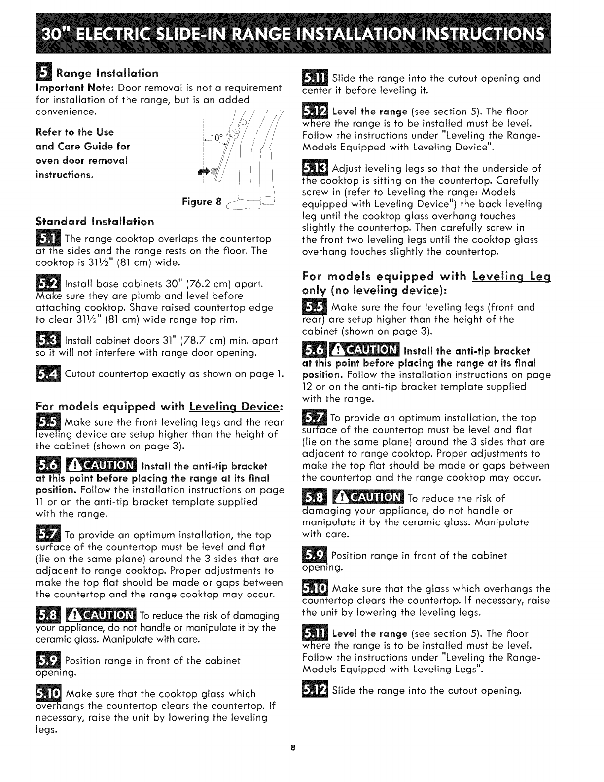
Range Installation
Important Note: Door removal is not a requirement
for installation of the range, but is an added
convenience.
Refer to the Use
and Care Guide for
oven door removal
instructions.
Figure 8
Standard Installation
The range cooktop overlaps the countertop
at t _sides and the range rests on the floor. The
cooktop is 311/2" (81 cm) wide.
Instalt base cabinets 30" (76.2 cm) apart.
Ma sure they are plumb and level before
attaching cooktop. Shave raised countertop edge
to clear 311/2" (81 cm) wide range top rim.
install cabinet doors 31" (78.7 cm) rain. apart
so it will not interfere with range door opening.
Cutout countertop exactly as shown on page 1.
For models equipped with Leveling Device:
Make sure the front leveling tegs and the rear
ng device are setup higher than the height of
the cabinet (shown on page 3).
Install the antl-tip bracket
at this point before placing the range at its final
position. Follow the installation instructions on page
11 or on the anti-tip bracket template supplied
with the range.
_To provide an optimum installation, the top
surface of the countertop must be level and flat
(tie on the same plane) around the 3 sides that are
adjacent to range cooktop. Proper adjustments to
make the top flat should be made or gaps between
the countertop and the range cooktop may occur.
To reduce the risk of damaging
your appliance, do not handle or manipulate it by the
ceramic glass. Manipulate with care.
Position range in front of the cabinet
opening.
Slide the range into the cutout opening and
center it before leveling it.
Level the range (see section 5). The floor
the range is to be installed must be level.
Follow the instructions under "Leveling the Range-
Models Equipped with Leveling Device".
te_coAdjust that the underside of
oktop is sitting on the countertop. Carefully
leveling legs
SO
screw in (refer to Leveling the range: Models
equipped with Leveling Device") the back leveling
leg until the cooktop glass overhang touches
slightly the countertop. Then carefully screw in
the front two leveling legs until the cooktop glass
overhang touches slightly the countertop.
For models equipped with LevelincLLeLeg
only (no leveling device):
Make sure the four leveling legs (front and
rear) are setup higher than the height of the
cabinet (shown on page 3).
Install the anti-tip bracket
at this point before placing the range at its final
position. Follow the installation instructions on page
12 or on the anti-tip bracket template supplied
with the range.
To provide an optimum installation, the top
sur :e of the countertop must be level and fiat
(tie on the same plane) around the 3 sides that are
adjacent to range cooktop. Proper adjustments to
make the top fiat should be made or gaps between
the countertop and the range cooktop may occur.
To reduce the risk of
damaging your appliance, do not handle or
manipulate it by the ceramic glass. Manipulate
with care.
Position range in front of the cabinet
opening.
Make sure that the glass which overhangs the
countertop clears the countertop, if necessary, raise
the unit by lowering the leveling legs.
Level the range (see section 5). The floor
w the range is to be installed must be level.
Follow the instructions under "Leveling the Range-
Models Equipped with Leveling Legs*'.
Make sure that the cooktop glass which
over angs the countertop clears the countertop. If
necessary, raise the unit by lowering the leveling
legs.
Slide the range into the cutout opening.
 Loading...