

Kenmore 40619 Quick Start Manual
iNSTALLATiON AND SERVICE MUST BE PERFORMED BY A QUALiFiED iNSTALLER.
iMPORTANT: SAVE FOR LOCAL ELECTRICAL iNSPECTOR'S USE.
READ AND SAVE THESE iNSTRUCTiONS FOR FUTURE REFERENCE.
FOR YOUR SAFETY: Do not store or use gasoline or other flammable vapors and liquids in
the vicinity of this or any other appliance.
Your new wall oven has been designed to fit a limited variety of cutout sizes to make the job of installing
easier. The first step of your installation should be to measure your current cutout dimensions and
compare them to the cutout dimensions chart below or next page for your model. You may find little or
no cabinet work will be necessary.
Do not remove spacers (if equipped) on the side walls and/or on the back of the built-in oven.
These spacers center the oven in the space provided. The oven must be centered to prevent excess heat buildup
that may result in heat damage or fire.
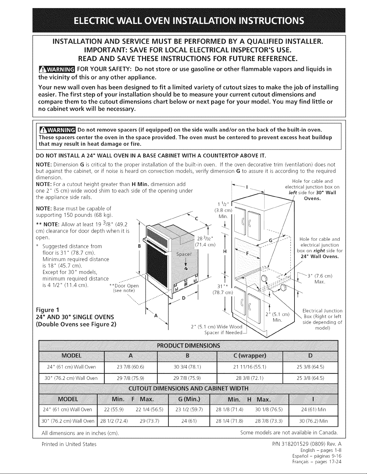
DO NOT INSTALL A 24" WALL OVEN IN A BASE CABINET WITH A COUNTERTOP ABOVE IT.
NOTE: Dimension G is critical to the proper installation of the built-in oven. If the oven decorative trim (ventilation) does not
but against the cabinet, or if noise is heard on convection models, verify dimension G to assure it is according to the required
dimension.
NOTE: For a cutout height greater than H Min. dimension add
one 2" (5 cm) wide wood shim to each side of the opening under
the appliance side rails.
NOTE: Base must be capable of
supporting 150 pounds (68 kg).
** NOTE: Allow at least 19 3/8" (49.2
cm) clearance for door depth when it is
open.
Suggested distance from B
floor is 31 " (78.7 cm). |
Minimum required distance
is 18" (45.7 cm).
Except for 30" models,
minimum required distance ..........
o
is 4 1/2" (11.4 cm). **Door Open
(see note)
28 3/32 "
(71.4 cm)
.... I ___,_ left side for 30" Wall
11/2"
(3.8 cm)
Min.
_" Holefor cableand
H box on right side for
_._ 24" Wall Ovens.
31"*
(78.7 cm)
Hole for cable and
electrical junction box on
Ovens.
electrical junction
(7.6 cm)
Max.
Figure 1
J Electrical Junction
24" AND 30" SINGLE OVENS
(Double Ovens see Figure 2)
24" (61 cm) Wall Oven 23 7/8 (60.6) 30 3/4 (78.1) 21 11/16 (55.1) 25 3/8 (64.5)
30" (76.2 cm) Wall Oven 29 7/8 (75.9) 29 7/8 (75.9) 28 3/8 (72.1) 25 3/8 (64.5)
24" (61 cm)Wall Oven 22 (55.9)
30" (76.2 cm)Wall Oven 28 1/2 (72.4)
22 1/4 (56.5) 23 1/2 (59.7)
29 (73.7) 24 (61)
All dimensions are in inches (cm).
Printed in United States
2" (5.1 cm) Wide Wood
Spacer if
28 1/8 (71.4) 30 1/8 (76.5) 24 (61) Min
28 1/4 (71.8) 28 7/8 (73.3) 30 (76.2) Min
Some models are not available in Canada.
P/N 318201529 (0809) Rev. A
English - pages 1-8
Espahol- p_iginas 9-16
Fran_ais - pages 17-24
Box(Right or left
side depending of
model)
Do not remove spacers (if equipped) on the side walls and/or on the back of the built-in oven.
These spacers center the oven in the space provided. The oven must be centered to prevent excess heat
buildup that may result in heat damage or fire.
11/2"
(3.8 cm)
",'- __LC" Min___
47 3/4" |
B (121.3 cm)
÷...-"
** _oor o -t
_ (29.2 cm)
(seenote) _2" (5.1 cm)
Electrical Junction Bc
(Right or left side
depending of model)
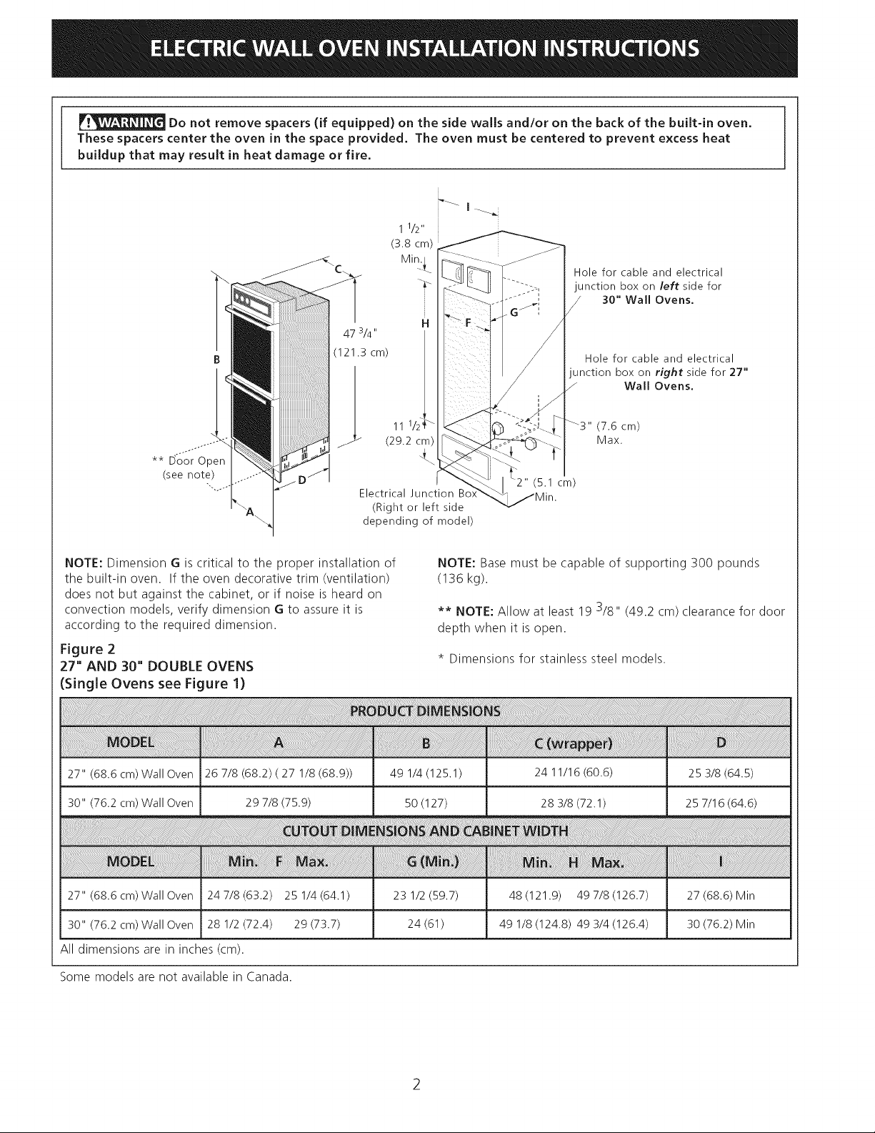
NOTE: Dimension G is critical to the proper installation of
the built-in oven. If the oven decorative trim (ventilation)
does not but against the cabinet, or if noise is heard on
convection models, verify dimension G to assure it is
according to the required dimension.
Figure 2
27" AND 30" DOUBLE OVENS
(Single Ovens see Figure 1)
Hole for cable and electrical
junction box on left side for
/ 30" Wall Ovens.
H
Hole for cable and electrical
junction box on right side for 27"
/ Wall Ovens.
11 1/2
NOTE: Base must be capable of supporting 300 pounds
(136 kg).
** NOTE: Allow at least 19 3/8" (49.2 cm) clearance for door
depth when it is open.
* Dimensions for stainless steel models.
27" (68.6 cm) Wall Oven 26 7/8 (68.2) ( 27 1/8 (68.9))
30" (76.2 cm) Wall Oven 29 7/8 (75.9)
27" (68.6 cm) Wall Oven 247/8(63.2) 25 1/4(64.1)
30" (76.2 cm) Wall Oven 28 1/2 (72.4) 29 (73.7)
All dimensions are in inches (cm).
Some models are not available in Canada.
49 1/4 (125.1) 24 11/16 (60.6) 25 3/8 (64.5)
50 (127) 28 3/8 (72.1) 25 7/16 (64.6)
23 1/2 (59.7) 48 (121.9) 49 7/8 (126.7) 27 (68.6) Min
24 (61) 49 1/8 (124.8) 49 3/4 (126.4) 30 (76.2) Min
Important Notes to the Installer
1. Read all instructions contained in these installation
instructions before installing the wall oven.
2. Remove all packing material from the oven
compartments before connecting the electrical supply
to the wall oven.
3. Observe all governing codes and ordinances.
4. Be sure to leavethese instructions with the consumer.
5. Oven door may be removed to facilitate installation.
6. THESEOVENS ARE NOT APPROVED FOR
STACKABLE OR SIDE=BY=SIDEINSTALLATION.
Important Note to the Consumer
Keep these instructions with your Use and Care Guide for
future reference.
Optional Item Available:
=A Decorative FillerTrim Kit for upper opening:
- Black : 903063-9100
- White : 903063-9101
This kit can be ordered for purchase by calling at a
ServiceCenter. The phone number islocated at the
back of your Use and Care Guide.
IMPORTANT SAFETY
2. Electrical Requirements
Theses appliances must be supplied with the proper
voltage and frequency, and connected to an individual,
properly grounded branch circuit, protected by a circuit
breaker or fuse, having amperage as noted on the rating
plate (the rating plate is located on the oven frame).
Observe all governing codes and local ordinances
1. A 3-wire or 4-wire single phase 120/208 or 120/240
Volt, 60 Hz AC only electrical supply is required on
a separate circuit fused on both sides of the line
(time-delay fuse or circuit breaker is recommended).
DO NOT fuse neutral. The fuse size must not exceed
the circuit rating of the appliance specified on the
nameplate.
NOTE: Wire sizes and connections must conform with
the fuse size and rating of the appliance in accordance
with the American National Electrical Code ANSI/NFPA
No. 70-latest edition, or with Canadian CSA Standard
C22.1, Canadian Electrical Code, Part 1, and local codes
and ordinances.
An extension cord should not be used
with this appliance. Such use may result in a fire,
electrical shock, or other personal injury.
INSTRUCTION
• Be sure your wall oven is installed and grounded
properly by a qualified installer or service
technician.
• This wall oven must be electrically grounded in
accordance with local codes or, in their absence,
with the National Electrical Code ANSI/NFPA
No.70= latest edition in United States, or with CSA
Standard C22.1, Canadian Electrical Code, Part 1, in
Canada.
Stepping, leaning or sitting on the
door of this wall oven can result in serious injuries
and can also cause damage to the wall oven.
Never use your wall oven for warming or heating
the room. Prolonged use of the wall oven without
adequate ventilation can be dangerous.
The electrical power to the oven must
be shut off while line connections are being made.
Failure to do so could result in serious injury or
death.
1. Carpentry
Refer to figure 1 or 2 for the dimensions applicable to
your appliance, and the space necessary to receive the
oven. The oven support surface may be solid plywood or
similar material, however the surface must be level from
side to side and front to rear.
2. These appliances should be connected to the fused
disconnect (or circuit breaker) box through flexible
armored or nonmetallic sheathed cable. The flexible
armored cable extending from the appliance should
be connected directly to the junction box. The
junction box should be located as shown in figure 1
or 2 with as much slack as possible remaining in the
cable between the box and the appliance, so it can
be moved if servicing is ever necessary.
3. A suitable strain relief must be provided to attach
the flexible armored cable to the junction box.
Electrical Shock Hazard
Electrical ground is required on this appliance.
Do not connect to the electrical supply until
appliance is permanently grounded.
Disconnect power to the junction box before
making the electrical connection.
This appliance must be connected to a
grounded, metallic, permanent wiring system,
or a grounding connector should be connected
to the grounding terminal or wire lead on the
appliance,
Do not use a gas supply line for grounding the
appliance.
Failure to do any of the above could result in a
fire, personal injury or electrical shock.
Waitatleastthree(3)hoursafter
receivingthisbuilt-inovenbeforeswitchingthepoweron
topreventpossibledamageto thebuilt-inovencontrol
atpoweron.
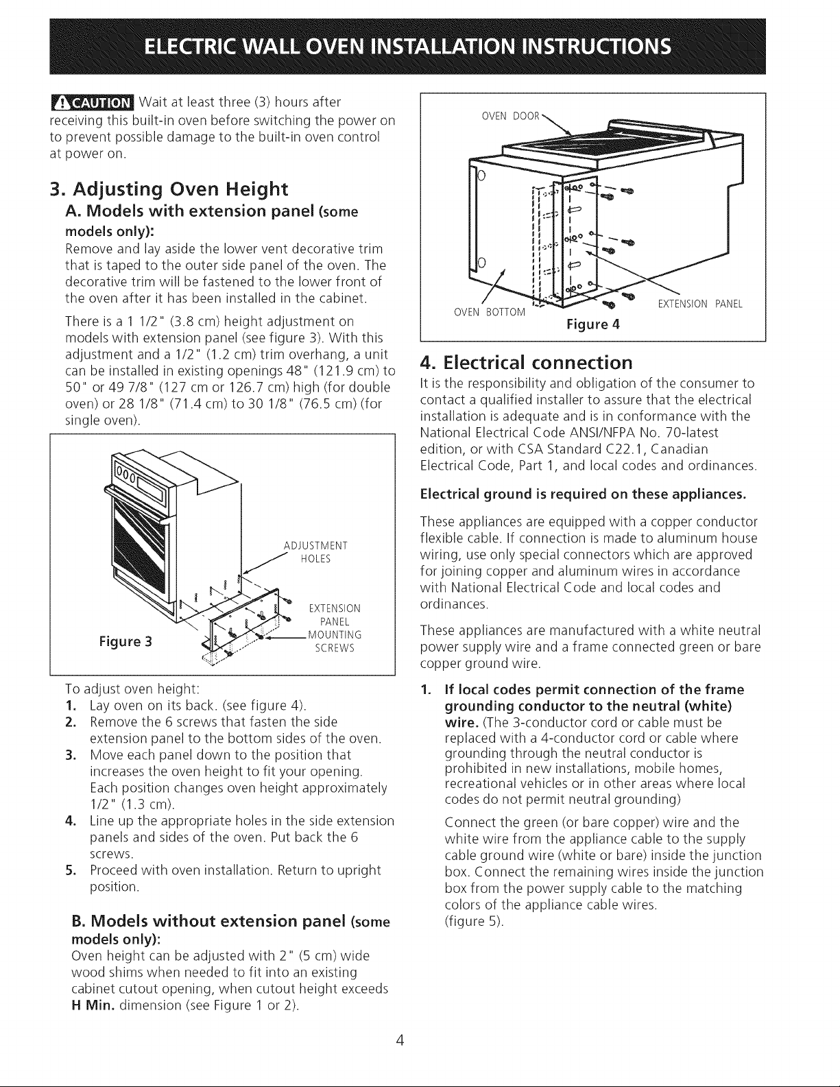
3. Adjusting Oven Height
A. Models with extension panel (some
models only):
Remove and lay aside the lower vent decorative trim
that is taped to the outer side panel of the oven. The
decorative trim will be fastened to the lower front of
the oven after it has been installed in the cabinet.
There is a 1 1/2" (3.8 cm) height adjustment on
models with extension panel (see figure 3). With this
adjustment and a 1/2" (1.2 cm) trim overhang, a unit
can be installed in existing openings 48" (121.9 cm)to
50" or 49 7/8" (127 cm or 126.7 cm) high (for double
oven) or 28 1/8" (71.4 cm) to 30 1/8" (76.5 cm) (for
single oven).
OVEN
OVEN BOTTOM
EXTENSIONPANEL
Figure 4
4. Electrical connection
It is the responsibility and obligation of the consumer to
contact a qualified installer to assure that the electrical
installation is adequate and is in conformance with the
National Electrical Code ANSI/NFPA No. 70-latest
edition, or with CSA Standard C22.1, Canadian
Electrical Code, Part 1, and local codes and ordinances.
Electrical ground is required on these appliances.
ADJUSTMENT
J HOLES
EXTENSION
PANEL
Figure 3
SCREWS
To adjust oven height:
1. Lay oven on its back. (see figure 4).
2. Remove the 6 screws that fasten the side
extension panel to the bottom sides of the oven.
3. Move each panel down to the position that
increases the oven height to fit your opening.
Each position changes oven height approximately
1/2" (1.3 cm).
4. Line up the appropriate holes in the side extension
panels and sides of the oven. Put back the 6
screws.
5. Proceed with oven installation. Return to upright
position.
B. Models without extension panel (some
models only):
Oven height can be adjusted with 2" (5 cm) wide
wood shims when needed to fit into an existing
cabinet cutout opening, when cutout height exceeds
H Min. dimension (see Figure 1 or 2).
These appliances are equipped with a copper conductor
flexible cable. If connection is made to aluminum house
wiring, use only special connectors which are approved
for joining copper and aluminum wires in accordance
with National Electrical Code and local codes and
ordinances.
These appliances are manufactured with a white neutral
power supply wire and a frame connected green or bare
copper ground wire.
.
If local codes permit connection of the frame
grounding conductor to the neutral (white)
wire. (The 3-conductor cord or cable must be
replaced with a 4-conductor cord or cable where
grounding through the neutral conductor is
prohibited in new installations, mobile homes,
recreational vehicles or in other areas where local
codes do not permit neutral grounding)
Connect the green (or bare copper) wire and the
white wire from the appliance cable to the supply
cable ground wire (white or bare) inside the junction
box. Connect the remaining wires inside the junction
box from the power supply cable to the matching
colors of the appliance cable wires.
(figure 5).
4
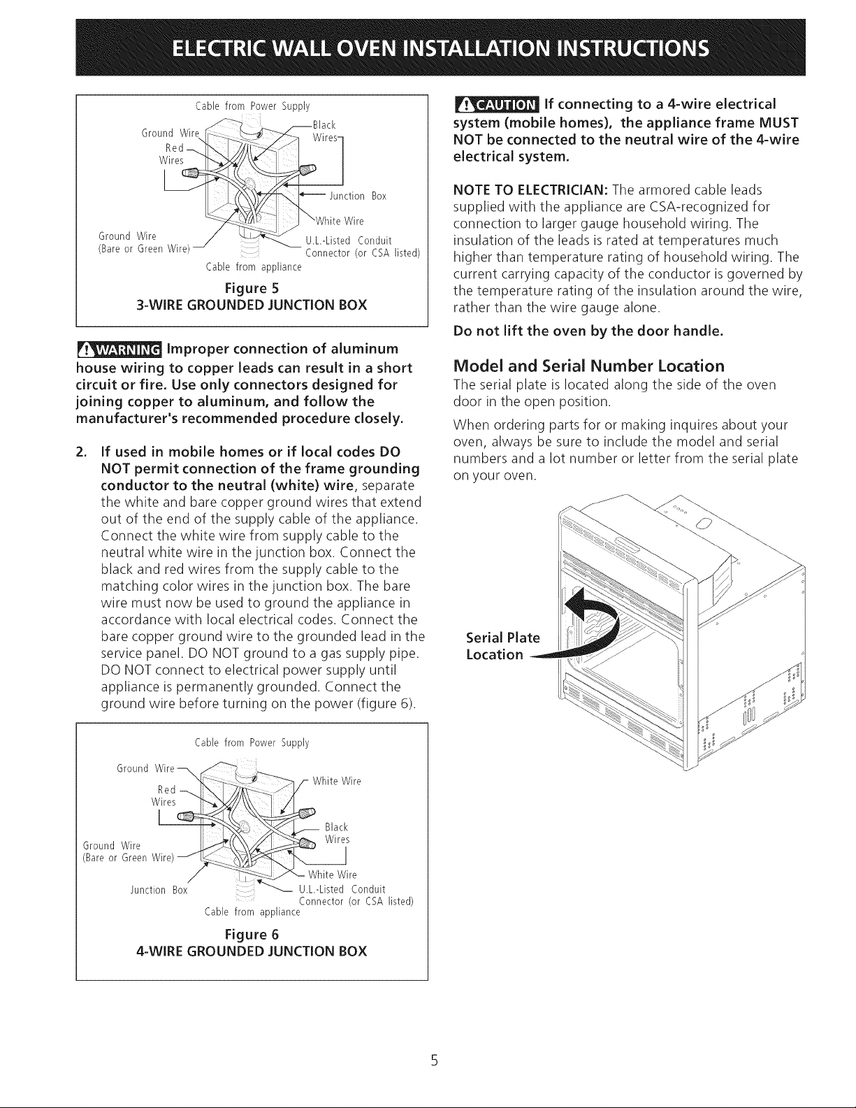
Cable from Power Supply
Ground Wire ...__.,___ _ Wires-1
_i_ - _ _Black
Red [/iiii--
If connecting to a 4-wire electrical
system (mobile homes), the appliance frame MUST
NOT be connected to the neutral wire of the 4-wire
electrical system.
W_ ction Box
Ground Wire U.L.-Listed Conduit
(Bare or Green Wire) :: Connector (or CSA listed)
Cable from appliance
"White Wire
Figure 5
3-WIRE GROUNDED JUNCTION BOX
Improper connection of aluminum
house wiring to copper leads can result in a short
circuit or fire. Use only connectors designed for
joining copper to aluminum, and follow the
manufacturer's recommended procedure closely.
. If used in mobile homes or if local codes DO
NOT permit connection of the frame grounding
conductor to the neutral (white) wire, separate
the white and bare copper ground wires that extend
out of the end of the supply cable of the appliance.
Connect the white wire from supply cable to the
neutral white wire in the junction box. Connect the
black and red wires from the supply cable to the
matching color wires in the junction box. The bare
wire must now be used to ground the appliance in
accordance with local electrical codes. Connect the
bare copper ground wire to the grounded lead in the
service panel. DO NOT ground to a gas supply pipe.
DO NOT connect to electrical power supply until
appliance is permanently grounded. Connect the
ground wire before turning on the power (figure 6).
NOTE TO ELECTRICIAN: The armored cable leads
supplied with the appliance are CSA-recognized for
connection to larger gauge household wiring. The
insulation of the leads is rated at temperatures much
higher than temperature rating of household wiring. The
current carrying capacity of the conductor is governed by
the temperature rating of the insulation around the wire,
rather than the wire gauge alone.
Do not lift the oven by the door handle.
Model and Serial Number Location
The serial plate is located along the side of the oven
door in the open position.
When ordering parts for or making inquires about your
oven, always be sure to include the model and serial
numbers and a lot number or letter from the serial plate
on your oven.
Serial Plate
Location
Cable from Power Supply
Ground Wire ___:
",_,-_.._.. b,;:_"_ /_ White Wire
Black
GroundWire W,res
(BareorGreenW re>J
j Uncti_. LW._hLys_}_/'r{ onduit
Cable from appliance
Figure 6
4-WIRE GROUNDED JUNCTION BOX
Connector (or CSA listed)
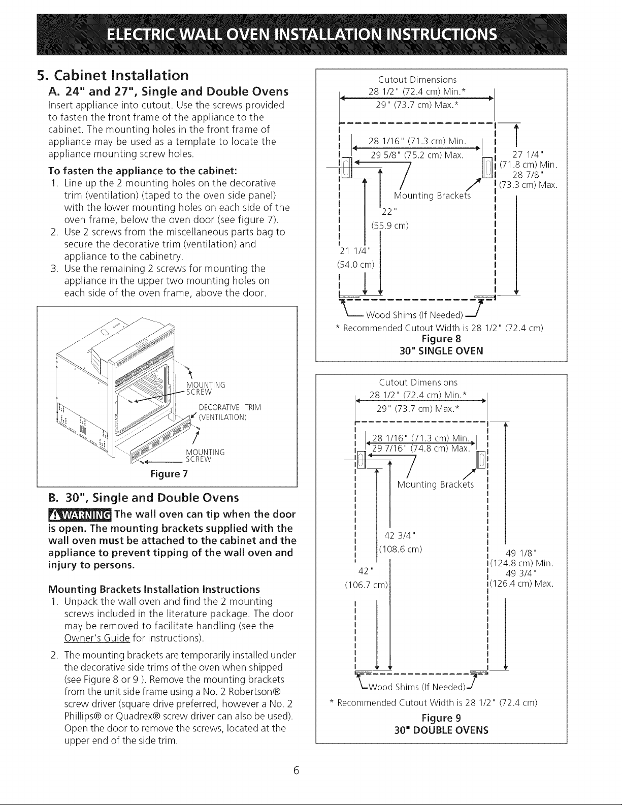
5. Cabinet Installation
A. 24" and 27", Single and Double Ovens
Insert appliance into cutout. Use the screws provided
to fasten the front frame of the appliance to the
cabinet. The mounting holes in the front frame of
appliance may be used as a template to locate the
appliance mounting screw holes.
To fasten the appliance to the cabinet:
1. Line up the 2 mounting holes on the decorative
trim (ventilation) (taped to the oven side panel)
with the lower mounting holes on each side of the
oven frame, below the oven door (see figure 7).
2. Use 2 screws from the miscellaneous parts bag to
secure the decorative trim (ventilation) and
appliance to the cabinetry.
3. Use the remaining 2 screws for mounting the
appliance in the upper two mounting holes on
each side of the oven frame, above the door.
Cutout Dimensions
< 28 1/2" (72.4 cm) Min.* >
r
I I
,!/14 28 1/16" (71.3cm) Min. /,I I
- 295/s"/752cm>Max "--',
Ilql < / " " I11
p , /
21 1/4" [
29" (73.7 cm) Max.*
I
T
27 1/4"
(71.8cm) Min.
28 7/8"
(73.3cm) Max.
54.ocm)|
_._-WoodShims(ifNeeded) P==_q
* RecommendedCutout Width is28 1/2" (72.4 cm)
Figure 8
30" SINGLE OVEN
MOUNTING
DECORATIVETRIM
(VENTILATION)
/
MOUNTING
SCREW
Figure 7
B. 30", Single and Double Ovens
The wall oven can tip when the door
is open. The mounting brackets supplied with the
wall oven must be attached to the cabinet and the
appliance to prevent tipping of the wall oven and
injury to persons.
Mounting Brackets Installation Instructions
1. Unpack the wall oven and find the 2 mounting
screws included in the literature package. The door
may be removed to facilitate handling (see the
Owner's Guide for instructions).
,
The mounting brackets are temporarily installed under
the decorative side trims of the oven when shipped
(see Figure 8 or 9 ). Remove the mounting brackets
from the unit side frame using a No. 2 Robertson@
screw driver (square drive preferred, however a No. 2
Phillips@or Quadrex@ screw driver can also be used).
Open the door to remove the screws, located at the
upper end of the side trim.
Cutout Dimensions
28 1/2" (72.4 cm) Min.*
29" (73.7 cm) Max.*
r
I
28 1/16" (71.3 cm) Min.
I 1797/16"/74.8cm/Ma×.'
8 / ,y
Mounting Brackets
42 3/4"
108.6 cm)
42
(106.7 cm)
_=_Wood Shims(If Needed)J=_-'J
* RecommendedCutout Width is28 1/2" (72.4 cm)
Figure 9
30" DOUBLE OVENS
49 1/8"
1(124.8 cm) Min.
m 49 3/4"
I(126.4 cm) Max.
6
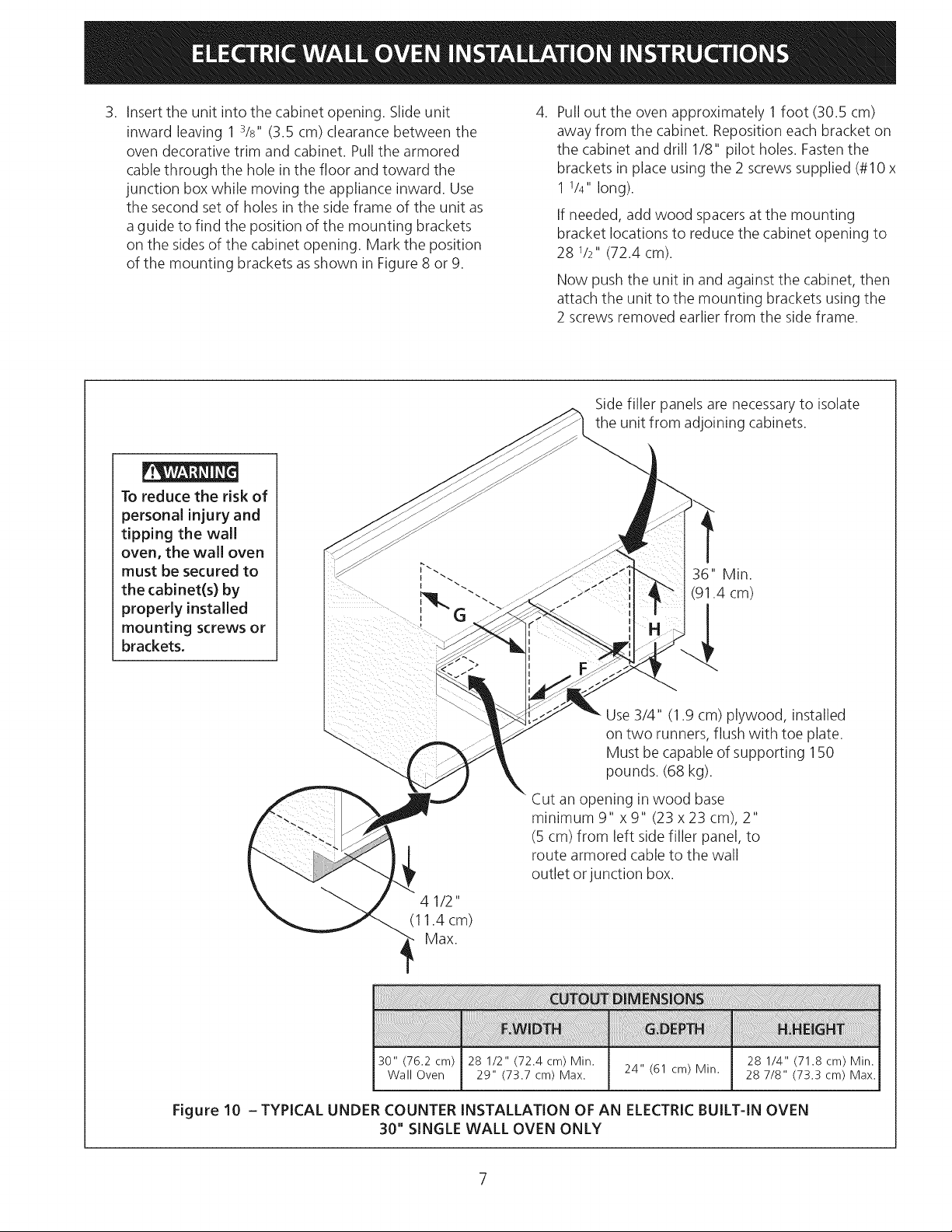
3. Insert the unit into the cabinet opening. Slide unit 4.
inward leaving 1 3/s" (3.5 cm) clearance between the
oven decorative trim and cabinet. Pull the armored
cable through the hole in the floor and toward the
junction box while moving the appliance inward. Use
the second set of holes in the side frame of the unit as
a guide to find the position of the mounting brackets
on the sides of the cabinet opening. Mark the position
of the mounting brackets as shown in Figure 8 or 9.
To reduce the risk of
personal injury and
tipping the wall
oven, the wall oven
must be secured to
the cabinet(s) by
properly installed
mounting screws or
brackets,
Pull out the oven approximately 1 foot (30.5 cm)
away from the cabinet. Reposition each bracket on
the cabinet and drill 1/8" pilot holes. Fasten the
brackets in place using the 2 screws supplied (#10 x
1 1/4" long).
If needed, add wood spacersat the mounting
bracket locations to reduce the cabinet opening to
28 1/2" (72.4 cm).
Now push the unit in and against the cabinet, then
attach the unit to the mounting brackets using the
2 screws removed earlier from the side frame.
Side filler panels are necessaryto isolate
the unit from adjoining cabinets.
36" Min.
(91.4 cm)
Use3/4" (1.9 cm) plywood, installed
on two runners, flush with toe plate.
Must be capable of supporting 150
pounds. (68 kg).
Cut an opening in wood base
minimum 9" x 9" (23 x 23 cm), 2"
(5 cm) from left side filler panel, to
route armored cable to the wall
outlet or junction box.
4 1/2"
(1 1.4 cm)
Max.
30" (76.2 cm) 28 1/2" (72.4 cm) Min. 28 1/4" (71.8 cm) Min.
Wall Oven 29" (73.7 cm) Max. 24" (61 cm) Min. 28 7/8" (73.3 cm) Max.
Figure 10 - TYPICAL UNDER COUNTER INSTALLATION OF AN ELECTRIC BUILT-IN OVEN
30" SINGLE WALL OVEN ONLY
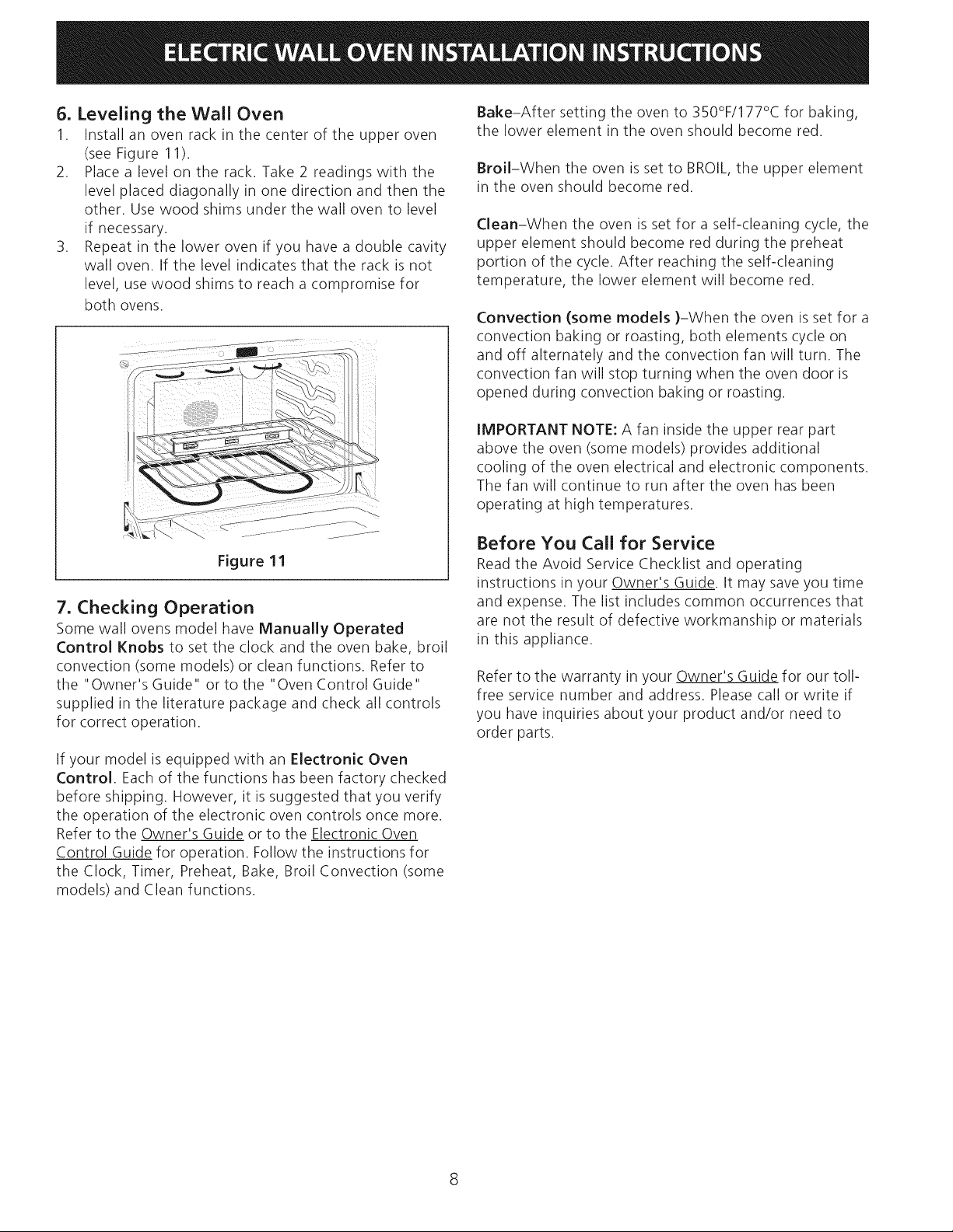
6. Leveling the Wall Oven
1. Install an oven rack in the center of the upper oven
(see Figure 11).
2. Place a level on the rack. Take 2 readings with the
level placed diagonally in one direction and then the
other. Use wood shims under the wall oven to level
if necessary.
3. Repeat in the lower oven if you have a double cavity
wall oven. If the level indicates that the rack is not
level, use wood shims to reach a compromise for
both ovens.
Figure 11
7. Checking Operation
Some wall ovens model have Manually Operated
Control Knobs to set the clock and the oven bake, broil
convection (some models) or clean functions. Refer to
the "Owner's Guide" or to the "Oven Control Guide"
supplied in the literature package and check all controls
for correct operation.
Bake-After setting the oven to 350°F/177°C for baking,
the lower element in the oven should become red.
Broil-When the oven is set to BROIL,the upper element
in the oven should become red.
Clean-When the oven is set for a self-cleaning cycle, the
upper element should become red during the preheat
portion of the cycle. After reaching the self-cleaning
temperature, the lower element will become red.
Convection (some models )-When the oven is set for a
convection baking or roasting, both elements cycle on
and off alternately and the convection fan will turn. The
convection fan will stop turning when the oven door is
opened during convection baking or roasting.
IMPORTANT NOTE: A fan inside the upper rear part
above the oven (some models) provides additional
cooling of the oven electrical and electronic components.
The fan will continue to run after the oven has been
operating at high temperatures.
Before You Call for Service
Read the Avoid Service Checklist and operating
instructions in your Owner's Guide. It may save you time
and expense. The list includes common occurrences that
are not the result of defective workmanship or materials
in this appliance.
Refer to the warranty in your Owner's Guide for our toll-
free service number and address. Please call or write if
you have inquiries about your product and/or need to
order parts.
if your model is equipped with an Electronic Oven
Control. Each of the functions has been factory checked
before shipping. However, it is suggested that you verify
the operation of the electronic oven controls once more.
Refer to the Owner's Guide or to the Electronic Oven
Control Guide for operation. Follow the instructions for
the Clock, Timer, Preheat, Bake, Broil Convection (some
models) and Clean functions.
8
 Loading...