

Kenmore 36314482100, 36314672100, 36314673100, 36314674100, 36314679100 Installation Guide
...
Installation instructions
for your new
Builto/n
Dishwasher
CAUTION:
If you received a damaged dishwasher,
you should immediatelycontact your
dealer or builder.
[] Two Phillips head countertop mounting screws taped to dishwasher
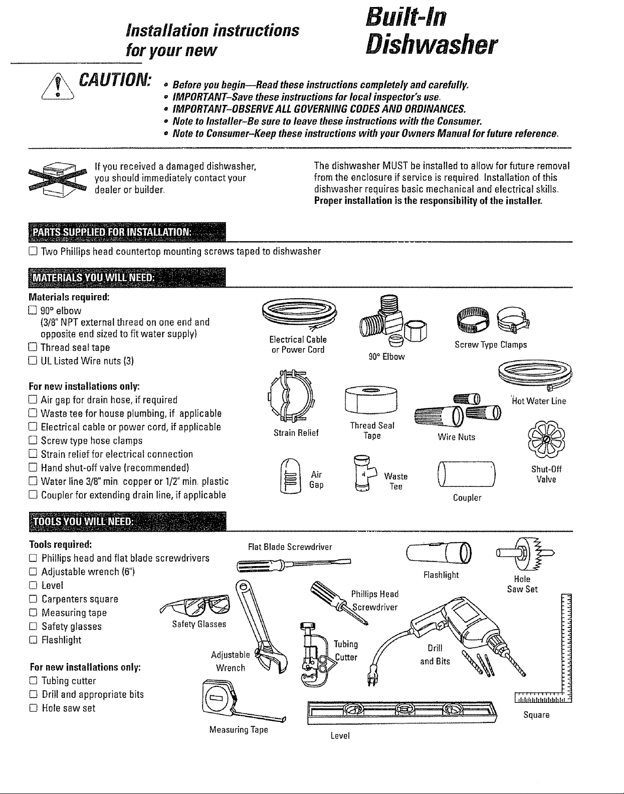
Materials required:
[] 90° elbow
(3/8"NPTexternal thread on one end and
opposite end sizedto fit water supply)
[] Thread seal tape
[] UL Listed Wire nuts (3)
o Before youbegin--Read these instructions completely and earefully_
o IMPORTANT-Save these instructions fur local inspector's use,
= IMPORTANT-OBSERVEALL GOVERNING CODESAND ORDINANCES.
= Note to Installer-Be sureto leave these instructions with the Consumer.
• Note to Consumer-Keep these instructions with your Owners Manual forfuture reference,
Electrical Cable
or Power Cord
The dishwasher MUST be installed to allow for future removal
from the enclosure ifservice is required. Installation of this
dishwasher requires basic mechanical and electrical skills_
Proper installation is the responsibility of the installer.
ScrewTypeClamps
90° Elbow
Fornew installationsonly:
[] Air gap for drain hose, if required
[] Waste tee for house plumbing, if applicable
[] Electrical cable or power cord, if applicable
[] Screwtype hose clamps
[] Strain relief for electrical connection
[] Hand shut-off valve (recommended)
[] Water line 3/8"rain copper or t/2" rain plastic
[] Coupler for extending drain line, if applicable
Toolsrequired:
[] Phillips head and flat blade screwdrivers
[] Adjustable wrench (6")
[] Level
[] Carpenters square
E) Measuring tape
[] Safety glasses
D Flashlight
Fornew installations only:
[] Tubing cutter
[] Drill and appropriate bits
O Hole saw set
SafetyGlasses
Adjustable_h
Wrench _'_ _/
MeasuringTape
ThreadSeal
StrainRelief Tape Wire Nuts
_ Air _ Waste @ _)Gap Tee
Coupler
Level
'LotWater Line
®
Square
!
Shut-Off
Valve
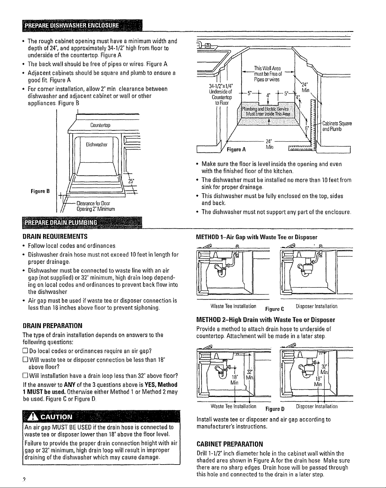
. The rough cabinet opening must have a minimum width and
depth of 24",and approximately 34-1/2"high from floor to
underside of the countertop FigureA
• The back wall should be free of pipes or wires, Figure A
• Adjacent cabinets should be square and plumb to ensure a
good fit Figure A
• Forcorner installation, allow 2" rain clearance between
dishwasher and adjacent cabinet or wall or other
appliances, Figure B
ThisWallArea
Pipesorwires
34-1/2"_+1/4"
Undersideof
Ceuntertop
toFloor
Countertop
Dishwasher
t
25"
FigureB
)our
Opening2"Minimum
DRAIN REQUIREMENTS
= Follow local codes and ordinances,
• Dishwasher drain hose must not exceed 10feet in length for
proper drainage,
o Dishwasher must be connected to waste line with anair
gap (not supplied) or 32"minimum, high drain loop depend-
ing on local codes and ordinances to prevent back flow into
the dishwasher
• Air gap must be used if waste tee or disposer connection is
less than 18inches above floor to prevent siphoning.
._abinetsSquare
andRumb
F FigureA
* Make sure the floor is level inside the opening and even
with the finished floor of the kitchen..
, The dishwasher must be installed no more than 10feet from
sink for proper drainage.
- This dishwasher must be fully enclosed on the top, sides
and back.
, The dishwasher must not support any part of the enclosure.
METHOD1-Air Gapwith Waste Tee or Disposer
WasteTeeInstallation FigureC DisposerInstallation
DRAIN PREPARATION
The type of drain installation depends on answers to the
following questions:
[] Dolocal codes or ordinances require an air gap?
[] Will waste tee ordisposer connection be less than 18"
above floor?
!_ Will installation have a drain loop less than 32"above floor?
If the answei" to ANY of the 3 questions above is YES,Method
1 MUST be used.OtherWiseeither Method t OrMethod 2 may
be used. Figure C or Figure D
An air gap MUST BE USEDif the drain hose is connected to
waste tee or disposer lower than 18"above the floor level
Failure toprovide the proper drain connection height with air
gap or32 minimum, high drainloop will result in improper
draining of the dishwasher which may cause damage,
METHOD 2-High Drain with Waste Tee or Disposer
Provide a method to attach drain hoseto underside of
countertop. Attachment will be made in a later step,
Mio
L..
WasteTeeinstallation
Install waste tee or disposer and air gap according to
manufacturer's instructions.
CABINET PREPARATION
DrillI-1t2" inch diameter hole in the cabinet wa!l within the
shaded area shown in Figure A for the drain hose Make sure
there are no sharp edges. Drain hose will be passed through
this hole and connected to the drain in a later step.
......
FigureD
DisposerInstallation
FORPERSONALSAFETY:REMOVEHOUSE
FUSEOROPENCIRCUITBREAKERBEFORE
BEGINNINGINSTALLATION.
DONOTUSEAN EXTENSIONCORDORADAPTER PLUG
WITH THIS APPLIANCE,.
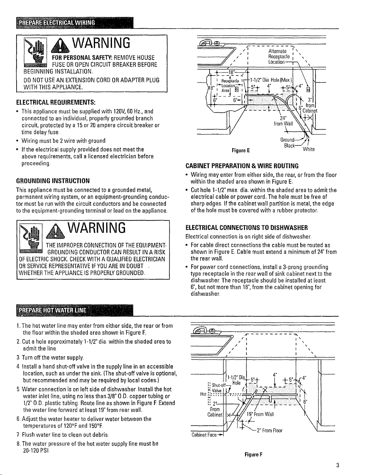
ELECTRICALREQUIREMENTS:
o This appliance must be supplied with t20V,60 Hz.,and
connected to an individual, properly grounded branch
circuit, protected by a 15or 20 ampere circuit breaker or
time delayfuse
, Wiring must be 2wire with ground
. If the electrical supply provided does not meetthe
above requirements, call a licensedelectrician before
proceeding+
GROUNDING INSTRUCTION
This appliance must be connected to a groundedmetal,
permanent wiring system, or an equipment-grounding conduc-
tor must be run with the circuit conductors and be connected
to the equipment-grounding terminal or lead on the appliance.
WARNING
"// t'i- Alternate"__
i ReceptacleI
Cabinet
Groul
FigureE White
CABINET PREPARATION& WIRE ROUTING
. Wiring may enter from either side, the rear, or from the floor
within the shaded area shown in Figure E.
• Cut hole 1-1/2"max dia+within the shaded area to admitthe
electrical cable or power cord°The hole must be free of
sharp edges. If the cabinet wall partition is metal, the edge
of the hole must be covered with a rubber protector.
THEIMPROPERCONNECTIONOFTHEEQUIPMENT-
GROUNDINGCONDUCTORCANRESULTINA RISK
OFELECTRICSHOCK.,CHECKWITH A QUALIFIEDELECTRICIAN
ORSERVICEREPRESENTATIVEIFYOUAREtN DOUBT +
WHETHERTHEAPPLIANCEIS PROPERLYGROUNDED,
1.The hot water line may enter from either side, the rear or from
the floor within the shaded area shown in Figure E
2 Cut a hole approximately t-112"dia. within the shaded area to
admit the line
3 Turn offthe water supply..
4 Install a hand shut-off valve in the supply line in an accessible
location, such as under the sink. (Theshut-off valve is optional,
but recommended and may be required by local codes,)
5 Water connection is on left side of dishwasher Install the hot
water inlet Iine, using no less than 3/8"O,D,copper tubing or
1/2"0,O. plastic tubing Route line as shown in Figure E Extend
the water line fopxvard at least 19"from rear wall+
6 Adjust the water heater to deliver water between the
temperatures of 120% and 150°E.
7 Flush water line to clean out debris.
8,The water pressure of the hot water supply line must be
20-120PSi,
WARNING
ELECTRICALCONNECTIONS TO DISHWASHER
Electrical connectionis on right side of dishwasher.
• Forcable direct connections the cable must be routed as
shown in Figure E°Cable must extend a minimum of 24"from
the rear wail.
o Forpower cord connections, install a 3-prong grounding
type receptacle in the rear wall of sink cabinet next to the
dishwasher The receptacle should be installed at least
6",but not more than t8",from the cabinet opening for
dishwasher.
l;
From
Cabinet
19"FromWall
+€_
CabinetFace
2" FromFloor
FigureF
Do not remove the wood base until you are ready to install
the dishwasher The dishwasher will tip over when the door
isopened.
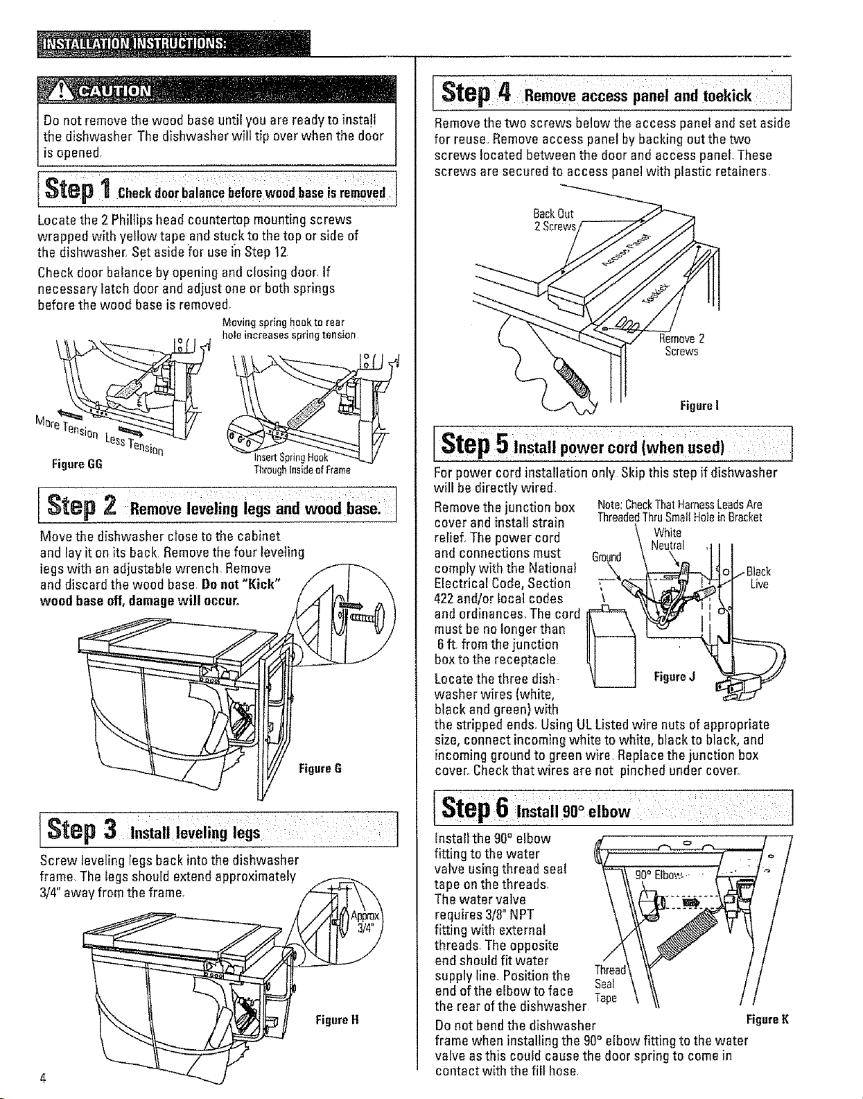
I St_p 1 Checkdoorbilan_eb_fo;ewood baseis removed
Locate the 2 Phillips head countertop mounting screws
wrapped with yellow tape and stuckto the top or side of
the dishwasher. Set aside for use in Step 12
Check door balance by opening and closing door. If
necessary Iatch door and adjust one or both springs
before the wood base is removed.
Moving spring hook to rear
hole increases spring tension
Mere Tensior_
FigureGG
nsertSpring
Throughinsideof Frame
I Step 2 Remove:leveling legs and woodbaSel ;
Move the dishwasher close to the cabinet
and lay iton its back. Removethe four leveling
legs with an adjustable wrench. Remove
and discard the wood base. Donot "Kick"
wood baseoff, damage will occur.
FigureG
[Step4 access panel and ,oekick
Removethe two screws below the access panel and set aside
for reuse.rRemove access panel by backing out the two
screws located between the door andaccess panel. These
screws are secured to access panel with plastic retainers.
BackOut
2Screws
Remove2
Screws
FigureI
Step5 Instatl power cord (when used)
Forpower cord installation only Sldpthis step if dishwasher
will be directly wired.
Removethe junction box
cover and install strain
relief. The power cord
and connections must
comply with the Nationat
Electrical Code,Section
422 and/or local codes
and ordinances. The cord
must be no longer than
6ft. from the junction
boxto the receptacle
Locate the three dish-
washer wires (white,
black and green) with
the stripped ends. Using UL Listed wire nuts of appropriate
size, connect incoming white to white, black to black, and
incoming ground to green wire, Replace the junction box
cover. Check that wires are not pinched under cover,,
Note:CheckThatHarnessLeedsAre
ThreadedThruSmallHoleinBracket
\ White
l____.J "g
[Step 3 ove,.g egs
Screw leveling legs back into the dishwasher
frame. The legs should extendapproximately
3/4" away from the frame. //_._"_
4
Step 6 ,.sta,9o° elbow I:
Install the 90° elbow
fitting to the water
valve using thread seal
tape onthe threads.
The water valve
requires 3/8"NPT
fitting with external
threads. The opposite
end should fit water
supply line. Position the Thread
end ofthe elbowto face Tape
the rear ofthe dishwasher
Donot bend the dishwasher Figure t{
frame when installing the 90° elbow fitting to the water
valve asthis could cause the doer spring to come in
contact with the fill hose.
Seal
]
continued
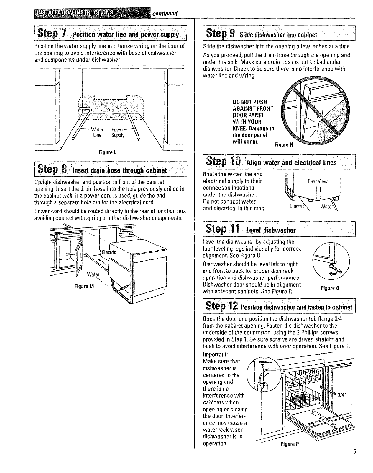
IStep ,.o..d
Position the water supply line and house wiring en the floor of
the opening to avoid interference with base of dishwasher
and components under dishwasher.
Water
Line Supply
FigureL
[Step 8 =.,o,t ra .:hose'th,o.ghc.bZ.ot
Upright dishwasher and position in front of the cabinet
opening Insert the drain hose into the hole previously drilled in
the cabinet wall If a power cord is used, guide the end
through aseparate hole cut for the electrical cord
Powercord should be routed directly to the rear of junction box
avoiding contact with spring or other dishwasher components.
[step9 ,,.,..,,e,,.,ooob,.o,
Slide the dishwasher into the opening a few inches at a time
As you proceed, pull the drain hose through the opening and
under the sink Make sure drain hose is not kinked under
dishwasher. Checkto be sure there is no interference with
water line and wiring.
DONOTPUSH
AGAINSTFRONT
DOORPANEL
WITH YOUR
KNEE,Damageto
thedoorpanel
will occur°
FigureN
(:Step10 Align water and electrical lines
Route the water line and
electrical supply to their
connection locations
under the dishwasher.
Do not connect water
and electrical inthis step.
L )
FigureM "
[Step 1Le. ,d,shw.sho.: :
Levelthe dishwasher by adjusting the
four leveling logs individually for correct
alignment, See Figure O
Dishwasher should be level left to right
and front to back for proper dish rack
operation and dishwasher performance.
Dishwasher door should be in alignment
with adjacent cabinets. See Figure R
[ Step 12 PositiOn dishwasher and fasten 1o cabinet 1
Openthe door and position the dishwasher tub flange 3/4"
from the cabinet opening Fasten the dishwasher to the
underside of the countertop, using the 2 Phillips screws
provided in Step I. Be sure screws are driven straight and
flush to avoid interference with door operation. See Figure R
Important:
Make sure that
dishwasher is
centered in the
openingand
there is no
interference with
cabinets when
opening or closing
the door Interfer-
ence may cause a
water leak when
dishwasher is in
operation. FigureP
Figure0
continued
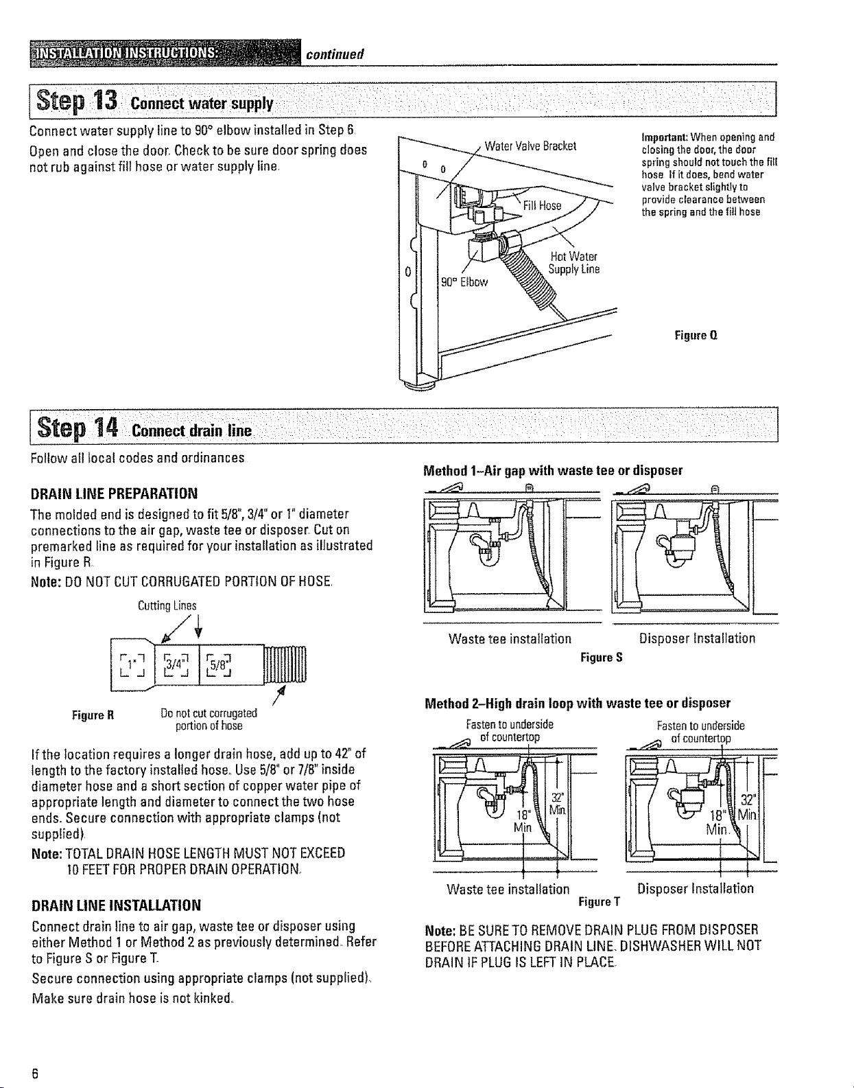
IStep13,co,.e='W.ter.uppUv : J
Connect water supply line to 90°elbow installed in Step 6. Important:Whenopeningand
Open and close the door_Checkto be sure door spring does WaterValveBracket closingthedoor,thedoor
not rub against fill hose or water supply line.
HotWater
SupplyLine
!Step 14 ico.. ctd,ai,,.e
spring should not touch the fi[E
hose tf it does, bend water
valve bracket slightly to
provide clearance between
the spring end the fi!] hose
Figure Q
Follow all local codes and ordinances
DRAIN LINE PREPARATION
The molded end is designed to fit 5t8",3/4"or I" diameter
connections to the air gap, waste tee or disposer Cut on
premarked line as required for your installation as illustrated
in Figure R
Note: DO NOTCUTCORRUGATEDPORTIONOFHOSE,
CuttingLines
FigureR DonotCUtcorrugated
portionof hose
If the location requires a longer drain hose, add up to 42"of
length to the factory installed hose°Use 5/8"or 7/8" inside
diameter hose and a short section of copper water pipe of
appropriate length and diameter to connectthe two hose
ends. Secure connection with appropriate clamps(not
supplied).
Note: TOTALDRAIN HOSELENGTHMUST NOT EXCEED
10FEETFORPROPERDRAIN OPERATION
DRAIN LINE INSTALLATION
Connect drain line to air gap, waste tee or disposer using
either Method I or Method 2 as previously determined Refer
to Figure S or Figure T.
Secure connection using appropriate clamps (not supplied),
Make sure drain hose is not kinked.
Method 1-Air gap with waste tee or disposer
_.___ _ __
Waste tee installation Disposer Installation
FigureS
Method 2-High drain loopwith waste tee or disposer
Fastentounderside
_ _ ofcountertop,
Fastentounderside
.._ of countertop
............. I
lll l Min
1
Waste tee installation
FigureT
Disposer Installation
Note: BE SURETO REMOVEDRAIN PLUGFROMDISPOSER
BEFOREATTACHINGDRAIN LINE. DISHWASHERWILL NOT
DRAIN IF PLUGIS LEFTIN PLACE,
i
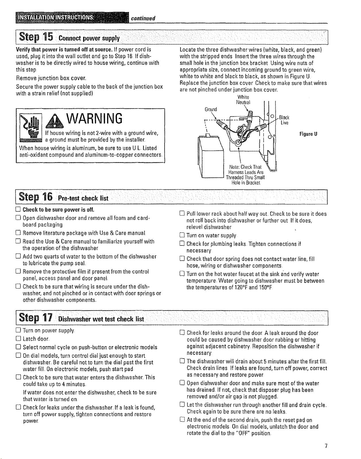
]Step15
continued
Verify that power is turnedoff at source.If power cord is
used, plug it intothe wall outlet andgo to Step 16 if dish-
washer is to be directly wired to house wiring, continue with
this step
Remove junction box cover_
Secure the power supply cable to the back of the junction box
with a strain relief (not supplied)
Locate the three dishwasher wires (white, black, and green)
with the stripped ends Insert the three wires through the
small hole in the junction box bracket Using wire nuts of
appropriate size, connect incoming ground to green wire,
white to white and black to black, as shown in Figure U
Replace the junction box cover Check to make sure that wires
ere not pinched under junction box cover_
White
Neutral
_'" Live
, WARNINGifhouse wiring is not 2-wire with a ground wire,
a ground musthe providedbythe installer,
When house wiring is aluminum, be sure to use UL Listed
anti-oxidant compound and aluminum-to-copper connectors.
_ _/_ FigureU
HoleinBracket
[Step16Pre4est check list i : i + + i: : i[
D Checkto he sure power is off.
[_3Opendishwasher door and remove all foam and card-
board packaging
[] Remove literature package with Use & Caremanual
[] Readthe Use & Care manuat to familiarize yourself with
the operation of the dishwasher
Ell Add two quarts of water to the bottom of the dishwasher
to lubricate the pump seal.
Ell Removethe protective film if present from the control
panel, access panel and door panel
[] Checkto be sure that wiring is secure under the dish-
washer, and not pinched orin contact with door springs or
other dishwasher components.
[] Pull lower rack about half way out. Checkto be sure it does
not roll back into dishwasher or further out ifit does,
reievel dishwasher
C] Turn on water supply
[] Checkfor plumbing leaks Tighten connections if
necessary
[] Checkthat door spring does not contact water line, fill
hose, wiring or dishwasher components.
[_ Turn on the hot water faucet at the sink and verify water
temperature. Water going to dishwasher must he between
the temperatures of 120_Fand 150°F
t
Step 17 DiShwasher wet test Checklist : i : _ :
[] Turn on power supply E3 Check for leaks around the door A leak around the door
[B Latch door.
[] Select normal cycle on push-button or electronic models
[] Ondial models, turn control dial just enough to start
dishwasher. Be careful notto turn the dia! past the first
water fill. On electronic models, push start pad
[] Checkto be sure that water enters the dishwasher`.This
could take up to 4 minutes.
tf water does not enter the dishwasher, check to be sure
that water is turned on.
E_ Check for leaks under the dishwasher. If a leak is found,
turn off power supply, tighten connections and restore
pewe£
could be caused by dishwasher door rubbing or hitting
against adjacent cabinetry Reposition the dishwasher if
necessary
The dishwasher will drain about 5 minutes after the first fill..
Check drain lines If leaks are found, turn off power, correct
as necessary and restore power
C3Open dishwasher door and make sure most of the water
has drained, if not, check that disposer plug has been
removed and/or air gap is not plugged.
[_ Letthe dishwasher run through another fill and drain cycle.
Check again to be sure there are no leaks.
[] At the end of the second drain, push the reset pad on
electronic models On dial models, unlatch the door and
rotate the dial to the "OFF" position.
!continued
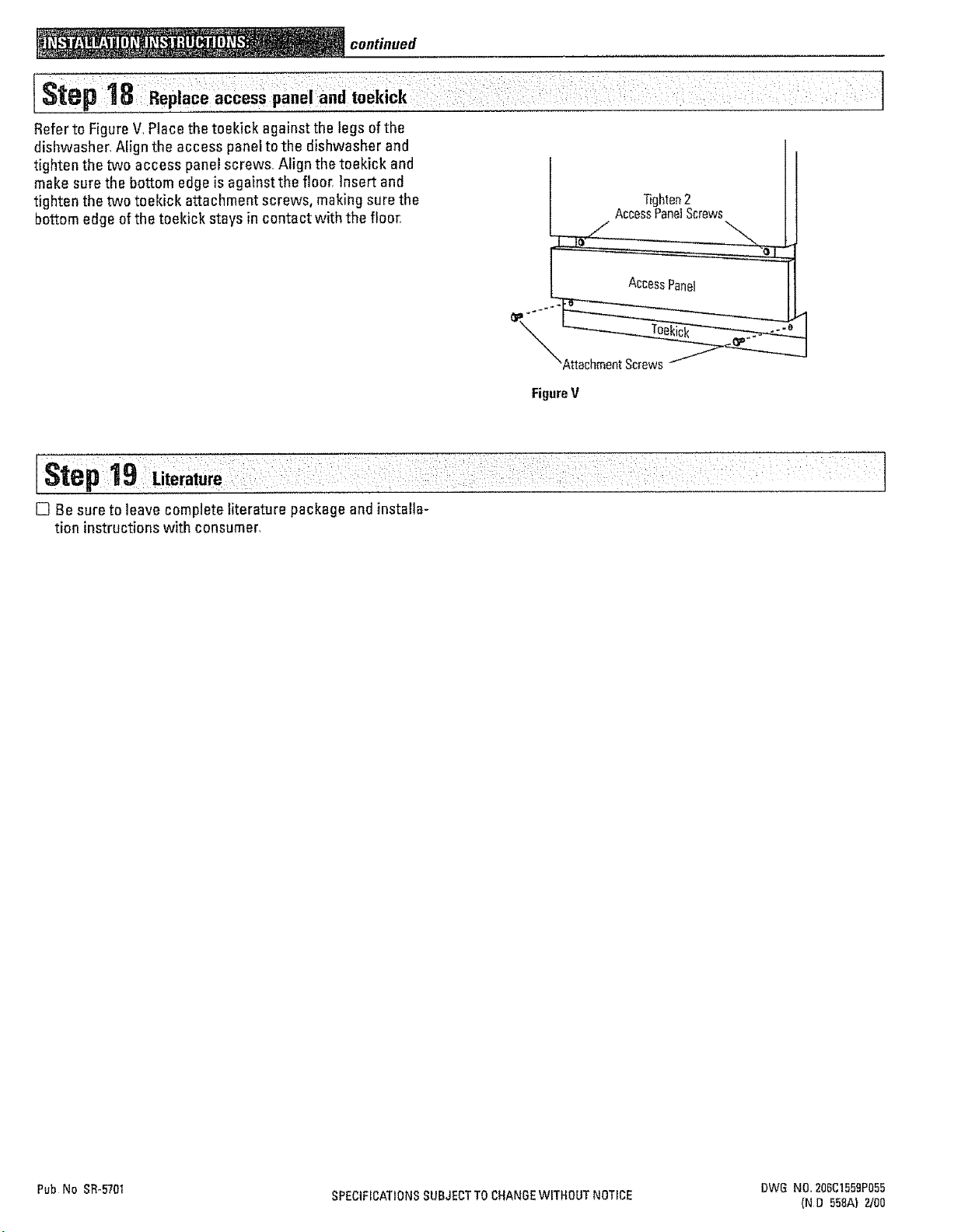
IStep18 Replaceaccess panei and toekiCk
Refer to Figure V1Place the toekick against the legs of the
dishwasher, Align the access panel to the dishwasher and
tighten the two access panel screws, Align the teekick and
make sure the bottom edge is against the floor, Insert and
tighten the two toekick attachment screws, making sure the Tighten2
bottom edge of the toekick stays in contact with the floor, AccessPanelScrews
AccessPanel
FigureV
[] Be sure to leave complete literature package and installa-
tion instructions with consumer,
Pub No SR-5701 SPECIFICATIONSSUBJECTTOCHANGEWITHOUT NOTICE DWG NO, 206C1559P055
(ND 55BAt 2/00
 Loading...