

Kenmore 3627361890, 3627361190 Owner’s Manual
CONT HT$
SAFE_
Important Safety Instructions ...........................2, 3, 17-20
Anti-Tip Device .................................................................2, 3, 12, 18
liNSTALLATION ....................................................2-t6
Dimensions and Clearances ..................................................2
Gas Pipe and Electric Outlet Locations ......................5, 6
Electrical Connections ..........................................................7, 8
Installing the Anti-Tip Device ...............................................I2
How to Convert the Range
for Use with LP Gas ..............................................................13-16
Kenmor'e
SERVICE
Minor Adjustments You Can Make ...................................45
Problem Solver ........................................................................46, 47
WARRANTY ....................................................... b_C k cover
MODELS:
73611,73618, 73619,
73915, 73919
@ @
WARN#,]G:if the informationin
this manual is not followed
exactly,a fire or explosionmay
resultcausingpropertydamage,
personalinjuryor death.
--Do not store or use gasoline or
other flammable vapors and li-
quidsinthevicinityof thisor any
otherappliance.
--WHAT TODOIFYOUSMELLGAS
oDo nottryto lightanyappliance.
RNSTALLATBONINSTRUCTIONS
Do not touch any electrical
switch;donot useany phonein
your building.
oimmediatelycall your gas sup=
plierfrom a neighbor's phone.
Follow the gas supplier's
instructions=
• If you cannot reach your gas
supplier,callthefire department.
--Installation and service must be
performedbya qualifiedinstaller,
serviceagencyorthegassupplier.
BEFORE YOU BEGnN
Read these instructions completely and
carefully.
IMPORTANT: Save these instructions for the
local electrical inspector's use.
INSTALLER: Leave these instructions with the
appliance after installation is completed.
OWNER: Keep this Use and Care Guide and
the Installation Instructions for future use.
This appliance must be properly grounded.
CAUTION
Do not attempt to operate the oven of this
range during a power failure.
IMPORTANT
Remove all packing material and literature
from oven before connecting gas and electri-
cal supply to range.
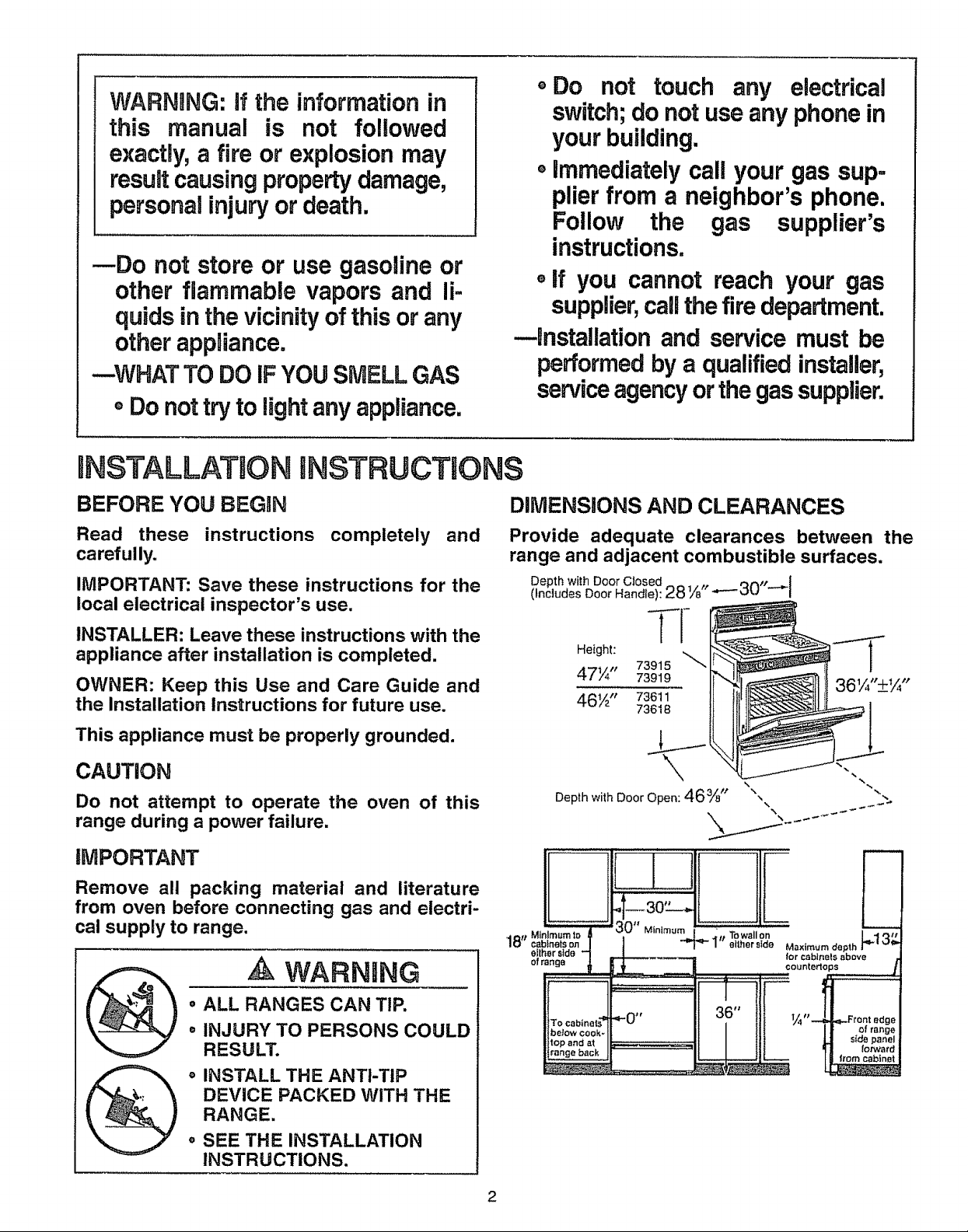
DIMENSIONS AND CLEARANCES
Provide adequate clearances between the
range and adjacent combustible surfaces.
Depth with Door Closed tt ,_^_t ..I
(Includes Door Handle): 28'A ---_u i
TI-
Height:
47¼" 73919
46½" 73611
Depthwith Door Open: 46%" ",
73915
73618
%
A WARNING
• ALL RANGES CAN TIP.
• INJURY TO PERSONS COULD
RESULT.
INSTALL THE ANTI-TIP
DEVICE PACKED WITH THE
RANGE.
, SEE THE INSTALLATION
INSTRUCTIONS.
TO cabinet_,= ._0 *r l_lJ Front edge
filth °'°°°°topand at _:::
2
lVlPORTANT SAFETY INSTRUCTIONS
_lnstallation of this range must conform with local
__ codes, or in the absence of local codes, with the
National Fuel Gas Code, ANSi Z223, latest edition.
This range has been design-certified by the American
_i Gas Association according to ANSI Z21.1, latest edF
tion. As with any appliance using gas and generating
heat, there are certain safety precautions you should
:follow. You will find these precautions at the beginning
:of the Use and Care section of this book Read them
carefuilyo
e Have your range installed by a qualified installer or
service technician.
, "(our range must be electrically grounded in accor-
dance with local codes or, in the absence of local
codes, in accordance with the National Electrical
Code (ANSI/NFPA 70, latest edition) See Electrical
Connections in this section
o Before installing your range on linoleum or any other
synthetic floor covering, make sure the floor covering
can withstand 180°R without shrinking, warping or
discoloring. Do not install the range over carpeting
unless a sheet of l/4-inch4hick plywood or similar
insulator is placed between the range and carpeting.
o Make sure the wall coverings around the range can
withstand heat generated by the range up to 200°R
o Avoid placing cabinets above the ranger To reduce
the hazard caused by reaching over the open flames
of operating burners, install over the range a ventila-
tion hood that projects forward at least 5 inches
beyond the front of the cabinets
The ventilating hood must be constructed of sheet
metal not less than 040122 inch thick. Install above
the cooking top with a (_tearance of not less than 1/4
inch between the hood and the underside of the
combustible material or metal cabinet. The hood
must be at least as wide as the appliance and cen-
tered over the appliance° Clearance between the
cooking surface and the ventilation hood surface
MUST NEVER BE LESS THAN 24 INCHES.
o if cabinets are placed above the range, allow a mini-
mum clearance of 30 inches between the cooking
surface and the bottom of unprotected cabinets.
° if a 30-inch clearance between cooking surface and
overhead combustible material or metal cabinets
cannot be maintained, protect the underside of the
cabinets above the cooking top with not less than
1/4-inch insulating millboard covered with sheet
metal not less than 0.0122 inch thick.
o Clearance between the cooking surface and protect-
ed cabinets MUST NEVER BE LESS THAN 24
INCHES, The vertical distance from the plane of the
cooking surface to the bottom of adjacent overhead
cabinets extending closer than 1 inch to the plane of
the range sides must not be less than 18 inches.
(Se e Dimensions and Clearances in this section.)
° Caution: items of interest to children should not be
stored in cabinets above a range or on the back-
splash of a range--children climbing on the range to
reach items could be seriously injured
WARNaNG
All ranges can tip and injury could
result. To prevent accidental tipping
of the range, attach an approved
Anti-Tip device to the wail. (See
Installing the Anti-Tip Device in this
section..) To check if the device is
installed and engaged properly,
carefully tip the range forward° The
Anti-Tip device should engage and
prevent the range from tipping over,.
if you pull the range out from the wall for any reason,
make sure the Anti-Tip device is engaged when you
push the range back against the wall
o For your safety, never use your range for warming
or heating the room Your oven and cooktop are not
designed to heat your kitchen. Top burners should
not be operated without cookware on the grates.
Such abuse could result in fire and damage to your
range and will void your warranty.
o Do not store or use combustible materials, gasoline
or other flammable vapors and liquids in the vicinity
of this or any other appliance. Explosions or fires
could result°
, Do not use oven for a storage area° Items stored in
the oven can ignite,
o Do not let cooking grease or other flammable mate-
rials accumulate in or near the range,
nnstaUgationinstructions
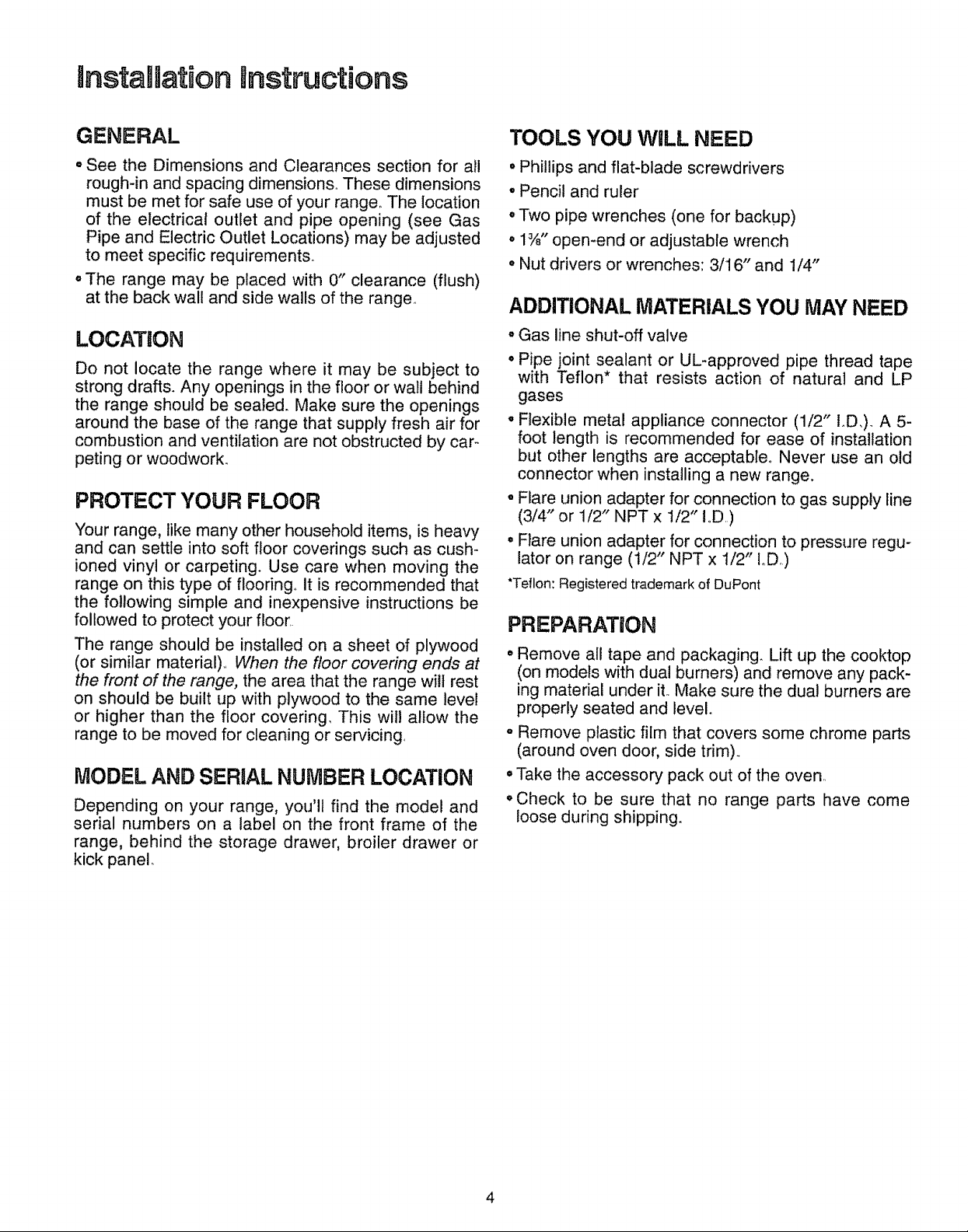
GENERAL
• See the Dimensions and Clearances section for all
rough-in and spacing dimensions,. These dimensions
must be met for safe use of your range. The location
of the electrical outlet and pipe opening (see Gas
Pipe and Electric Outlet Locations) may be adjusted
to meet specific requirements.
oThe range may be placed with 0" clearance (flush)
at the back wall and side walls of the range.
LOCATION
Do not locate the range where it may be subject to
strong drafts. Any openings in the floor or wall behind
the range should be sealed. Make sure the openings
around the base of the range that supply fresh air for
combustion and ventilation are not obstructed by car-
peting or woodwork.
PROTECT YOUR FLOOR
Your range, like many other household items, is heavy
and can settle into soft floor coverings such as cush-
ioned vinyl or carpeting. Use care when moving the
range on this type of flooring° it is recommended that
the following simple and inexpensive instructions be
followed to protect your floor..
The range should be installed on a sheet of plywood
(or similar material)., When the floor covering ends at
the front of the range, the area that the range wilt rest
on should be built up with plywood to the same level
or higher than the floor covering, This will allow the
range to be moved for cleaning or servicing,
MODEL AND SERIAL NUMBER LOCATION
Depending on your range, you'll find the model and
serial numbers on a label on the front frame of the
range, behind the storage drawer, broiler drawer or
kick panel.
TOOLS YOU WiLL NEED
• Phillips and flat-blade screwdrivers
• Pencil and ruler
° Two pipe wrenches (one for backup)
o 1%" open-end or adjustable wrench
• Nut drivers or wrenches: 3/16" and 1/4"
ADDITIONAL MATERIALS YOU MAY NEED
- Gas line shut-off valve
° Pipe joint sealant or UL-approved pipe thread tape
with Teflon* that resists action of natural and LP
gases
. Flexible metal appliance connector (1/2" I.D,). A 5-
foot length is recommended for ease of installation
but other lengths are acceptable° Never use an old
connector when installing a new range.
oFlare union adapter for connection to gas supply fine
(3/4" or 1/2" NPT x 1/2" !,,D,)
° Flare union adapter for connection to pressure regu-
lator on range (t/2" NPT x 1/2" IoD,)
"Teflon: Registered trademark of DuPont
PREPARATION
• Remove all tape and packaging. Lift up the cooktop
(on models with dual burners) and remove any pack-
ing material under it..Make sure the dual burners are
properly seated and level.
. Remove plastic film that covers some chrome parts
(around oven door, side trim)_
° Take the accessory pack out of the oven..
• Check to be sure that no range parts have come
loose during shipping.
4
Step t
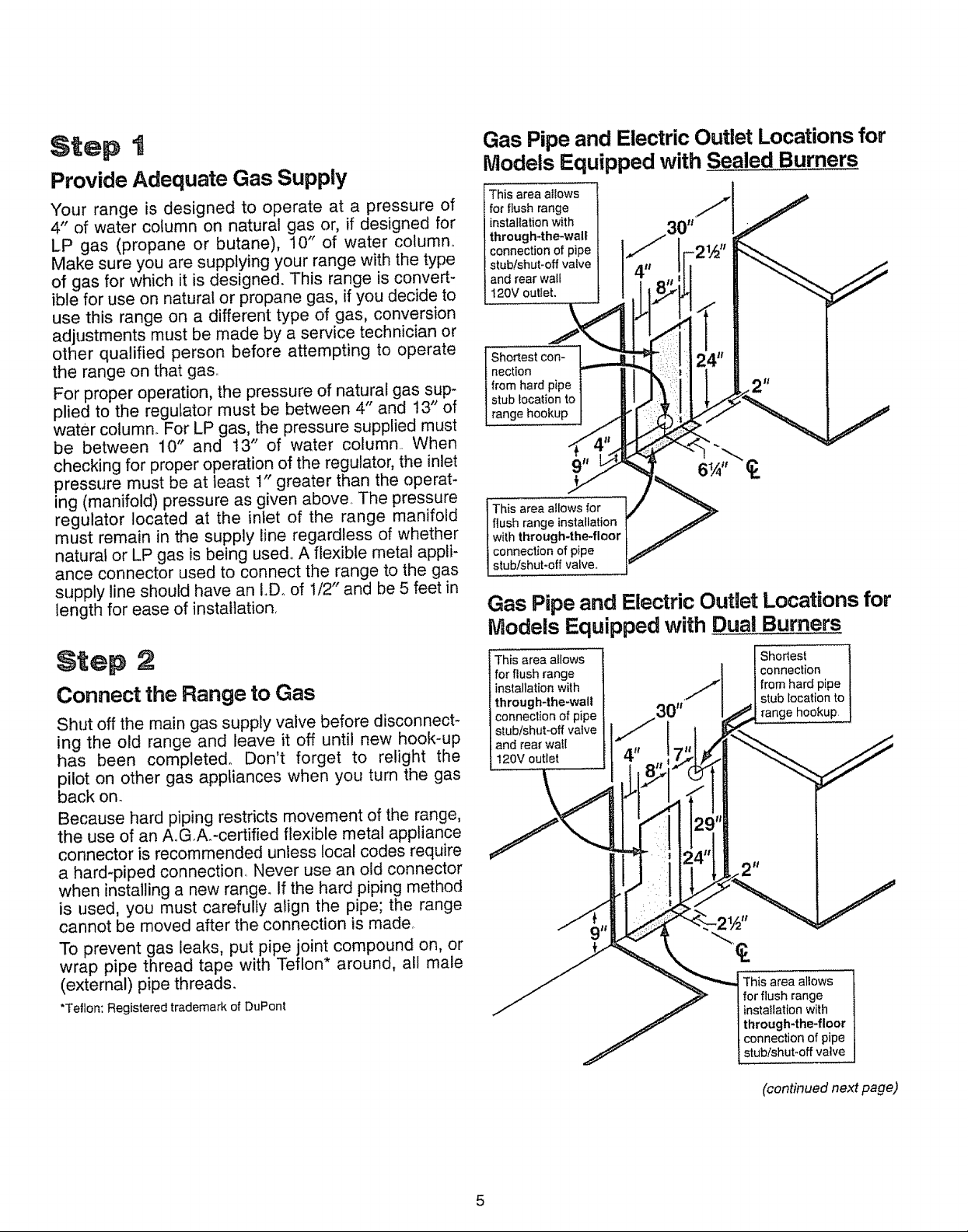
Provide Adequate Gas Supply
Your range is designed to operate at a pressure of
4" of water column on natural gas or, if designed for
LP gas (propane or butane), 10" of water column°
Make sure you are supplying your range with the type
of gas for which it is designed. This range is convert-
ible for use on natural or propane gas, if you decide to
use this range on a different type of gas, conversion
adjustments must be made by a service technician or
other qualified person before attempting to operate
the range on that gas.
For proper operation, the pressure of natural gas sup-
plied to the regulator must be between 4" and 13" of
water column. For LP gas, the pressure supplied must
be between 10" and t3" of water column.. When
checking for proper operation of the regulator, the inlet
pressure must be at least 1" greater than the operat-
ing (manifold) pressure as given above. The pressure
regulator located at the inlet of the range manifold
must remain in the supply line regardless of whether
natural or LP gas is being used,. A flexible metal appli-
ance connector used to connect the range to the gas
supply line should have an I.,Doof 1/2" and be 5 feet in
length for ease of installation,
Gas Pipe and ElectricOutlet Locations for
Models Equipped with Sealed Burners
This area abws
for flush range
installation with
through-the-walt
connection of pipe
stub/shut-off valve
and rear walt
t20V outiet,
I Shortest con-
nection
from hard pipe
stub location to
range hookup
This area abws for
I flush range installation
I with through-the-floor
conneclion of pipe
1stub/shut-off valve,
Gas Pipe and Electric Outlet Locations for
Models Equipped with Dual Burners
Step 2
Connect the Range to Gas
Shut off the main gas supply valve before disconnect-
ing the old range and leave it off until new hook-up
has been completed° Don't forget to relight the
pilot on other gas appliances when you turn the gas
back on.
Because hard piping restricts movement of the range,
the use of an AoGA:certified flexible metal appliance
connector is recommended unless local codes require
a hard-piped connection,. Never use an old connector
when installing a new range_ If the hard piping method
is used, you must carefully align the pipe; the range
cannot be moved after the connection is made,
To prevent gas leaks, put pipe joint compound on, or
wrap pipe thread tape with Teflon* around, all male
(external) pipe threads.
*Teflon: Registered trademark of DuPont
This area allows
for flush range
installation with
through-the-walt
connection of pipe
stub/sh_Jt-off vatve
and rear wail
120V outlet
Shortest 1
connection J
from hard pipe J
stub location to J
range hookup j
This area allows
for flush range
installation with
through-the-floor
connection of pipe
stub/shut-off valve
(continued next page)
5
instanUation Bnstructions (continued)
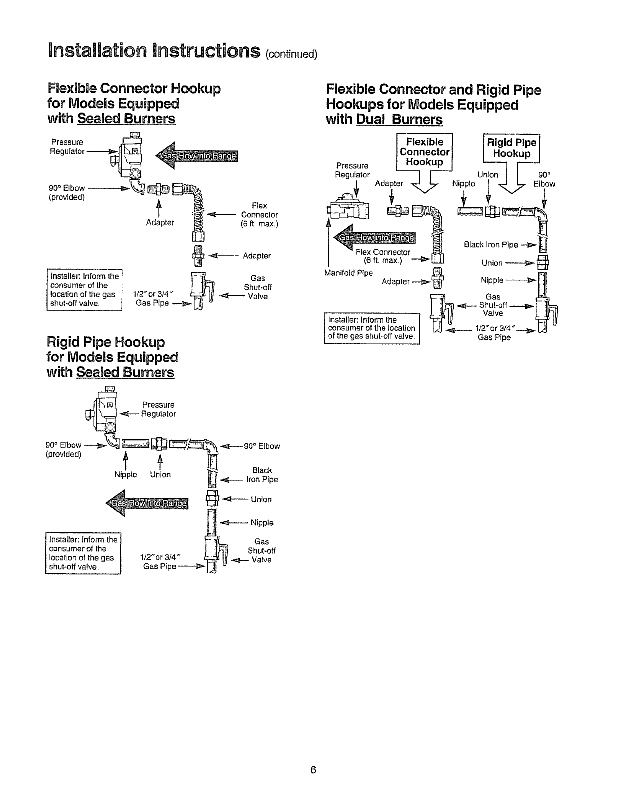
Flexible Connector Hookup
for Models Equipped
with Sealed,Burners
Regulator
90=Elbow
(provided) _ Flex
Adapter (6 ft max,)
@ -.,_----- Adapter
I fnstalter: Informthe
consumer of the
localion of the gas
,shut-off valve
I/2" or 3/4"
Gas Pipe --.4_,1_ _
Connector
Shut-off
.,,=_t_-__Valve
Rigid Pipe Hookup
for Models Equipped
with Sealed Burners
Flexible Connector and Rigid Pipe
Hookups for Models Equipped
with Dual Burners
Gas
__ Pressure
Regulalor
,0.o.,0o0,€ g
Nipple Union _.f_ IronPipe
.I_-,,_---_ Nipple
Installer: Inform the _ Gas
consumer of the f ;l_ll Shut-off
location of the gas t/2"or 3/4" b._ I]I _ Valve
shut-off valve, Gas Pipe _ L_ "
6
1. Install a manual gas line shut-off valve in the gas
line in an easily accessed location outside of the
range_ Make sure everyone operating the range
knows where and how to shut off the gas supply to
the range.
2. Instalt male 1/2" flare union adapter to the 1/2" NPT
internal thread elbow at inlet of pressure regulator.
On models equipped with dual burners, install
the male pipe thread end of the !/2" flare union
adapter to the 1/2" NPT internal thread at inlet of
pressure regulator Use a backup wrench on the
regulator fitting to avoid damage
When installing the range from the front, remove the
90 ° elbow for easier installation
3. Install male 1/2" or 3/4" flare union adapter to the
NPT internal thread of the manual shut-off valve,
taking care to back-up the shut-off valve to keep it
from turning
4. Connect flexible metal appliance connector to the
adapter on the range_ Position range to permit con-
nection at the shut-off valve.
5. When all connections have been made, make sure
all range controls are in the off position and turn on
the main gas supply valve. Use a liquid leak detec-
tor at a!l joints and connections to check for leaks in
the system.
CAUTION: DO NOT USE A FLAME TO CHECK
FOR GAS LEAKS.
When using test pressures greater than 1/2 psig to
pressure test the gas supply system of the residence,
disconnect the range and individual shut-off valve
from the gas supply piping. When using test pres-
sures of 1/2 psig or less to test the gas supply sys-
tem, simply isolate the range from the gas supply
system by closing the individual shut-off valve.
Step 3
Electrical Connections
Electrical Requirements
120-volt, 60 Hertz, properly grounded branch circuit
protected by a 15-amp or 20-amp circuit breaker or
time delay fuse
Extension Cord Cautions
Because of potential safety hazards associated with
certain conditions, we strongly recommend against
the use of an extension cord° However, if you still elect
to use an extension cord, it is absolutely necessary
that it be a UL-listed, 3-wire grounding-type appliance
extension cord and that the current carrying rating of
the cord in amperes be equivalent to, or greater than,
the branch circuit rating°
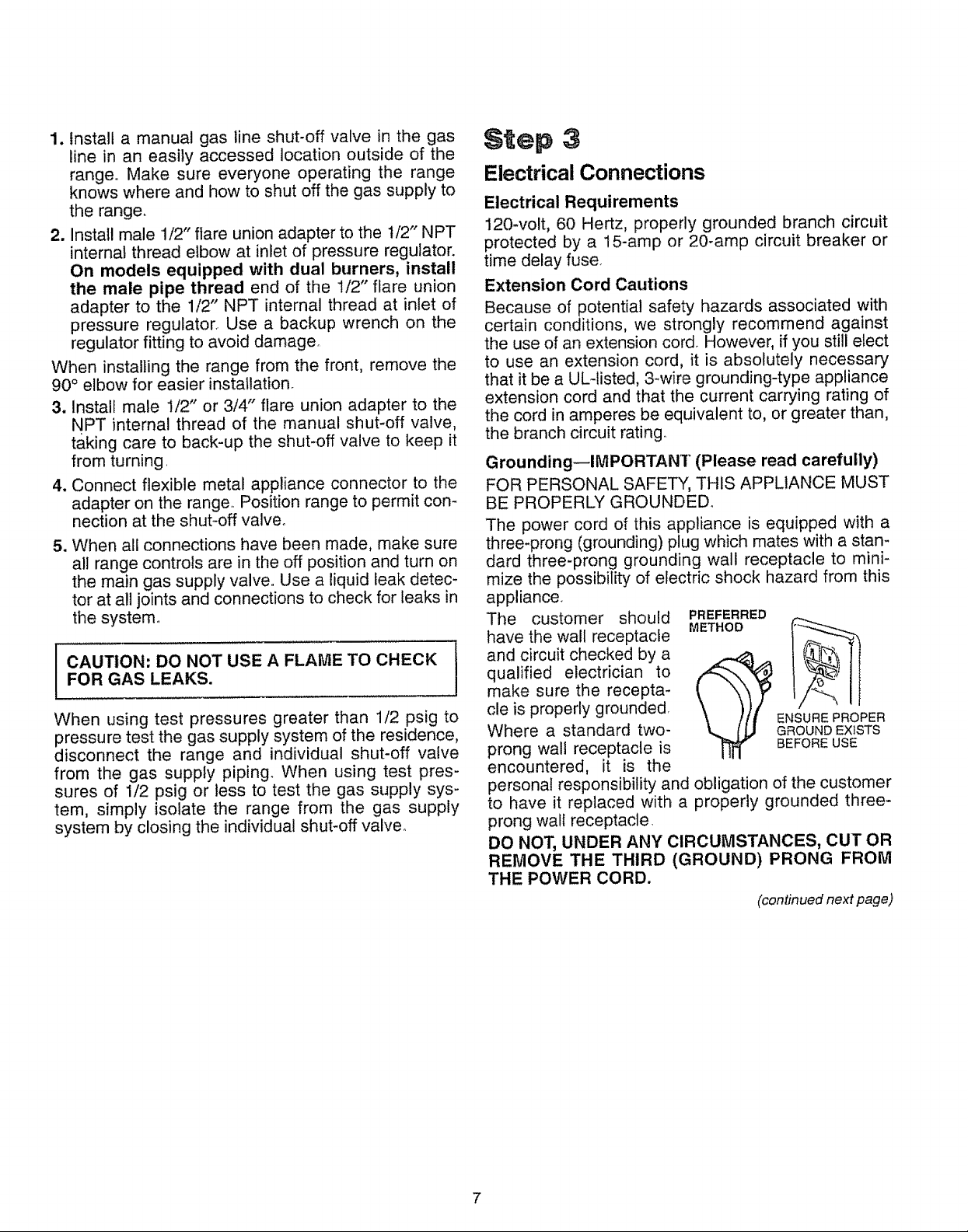
Grounding--IMPORTANT (Please read carefully)
FOR PERSONAL SAFETY, THIS APPLIANCE MUST
BE PROPERLY GROUNDED°
The power cord of this appliance is equipped with a
three-prong (grounding) plug which mates with a stan-
dard three-prong grounding wall receptacle to mini-
mize the possibility of electric shock hazard from this
appliance
The customer should
have the wall receptacle
and circuit checked by a
qualified electrician to
make sure the recepta-
cle is properly grounded
Where a standard two-
prong wall receptacle is
encountered, it is the
personal responsibility and obligation of the customer
to have it replaced with a properly grounded three-
prong wall receptacle
DO NOT, UNDER ANY CIRCUMSTANCES, CUT OR
REMOVE THE THIRD (GROUND) PRONG FROM
THE POWER CORD.
PREFERRED
METHOD
ENSURE PROPER
GROUND EXISTS
BEFORE USE
(continued next page)
InstanUationSnsttuctions <contin.ed>
A: Usage Situations where Appliance Power Cord
will be Disconnected.
An adapter may be used only on a 15-amp circuit° Do
not use an adapter on a 20-amp circuit. Where local
codes permit, a TEMPORARY CONNECTION may
be made to a properly grounded two-prong wall
receptacle by the use of a UL-listed adapter, available
at most hardware stores_ The larger slot in the adapter
must be aligned with the larger slot in the wall recep-
tacle to provide proper polarity in the connection of the
power cord.
(ADAPTER PLUGS NOT
TEMPORARY METHOD ._ ___
PERMITTED IN CANADA) _--_ ,_"
PRONGS/SLOTS
BEFORE USE
CAUTION: Attaching the adapter ground terminal
to the wall receptacle cover screw does not ground
the appliance unless the cover screw is metal, and
not insulated, and the wall receptacle is grounded
through the house wiring. The customer should
have the circuit checked by a qualified electrician
to make sure the receptacle is properly grounded.
N
B: Usage Situations where Appliance Power Cord
will be Disconnected.
Do not use an adapter plug in these situations
because disconnecting of the power cord places
undue strain on the adapter and leads to eventual fail-
ure of the adapter ground terminal° The customer
should have the two-prong wall receptacle replaced
with a three-prong (grounding) receptacle by a quali-
fied electrician before using the appliance°
The installation of appliances designed for mobile
home installation must conform with the Manufactured
Home Construction and Safety Standard, Title 24
CFR, Part 3280 (formerly the Federal Standard for
Mobile Home Construction and Safety, Title 24, HUD,
Part 280) or, when such standard is not applicable,
the Standard for Manufactured Home installations, lat-
est edition (Manufactured Home Sites, Communities
and Set-Ups), ANSI A225ol, latest edition, or with
local codes.
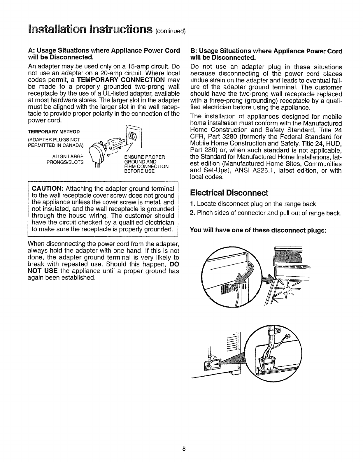
Electrical Disconnect
1. Locate disconnect plug on the range back.
2. Pinch sides of connector and putl out of range back,,
You will have one of these disconnect plugs:
When disconnecting the power cord from the adapter,
always hold the adapter with one hand_ If this is not
done, the adapter ground terminal is very likely to
break with repeated use. Should this happen, DO
NOT USE the appliance until a proper ground has
again been established°
8
Step 4
Seal the Openings
Seal any openings in the wall behind the range and
in the floor under the range when hookups are
completed,
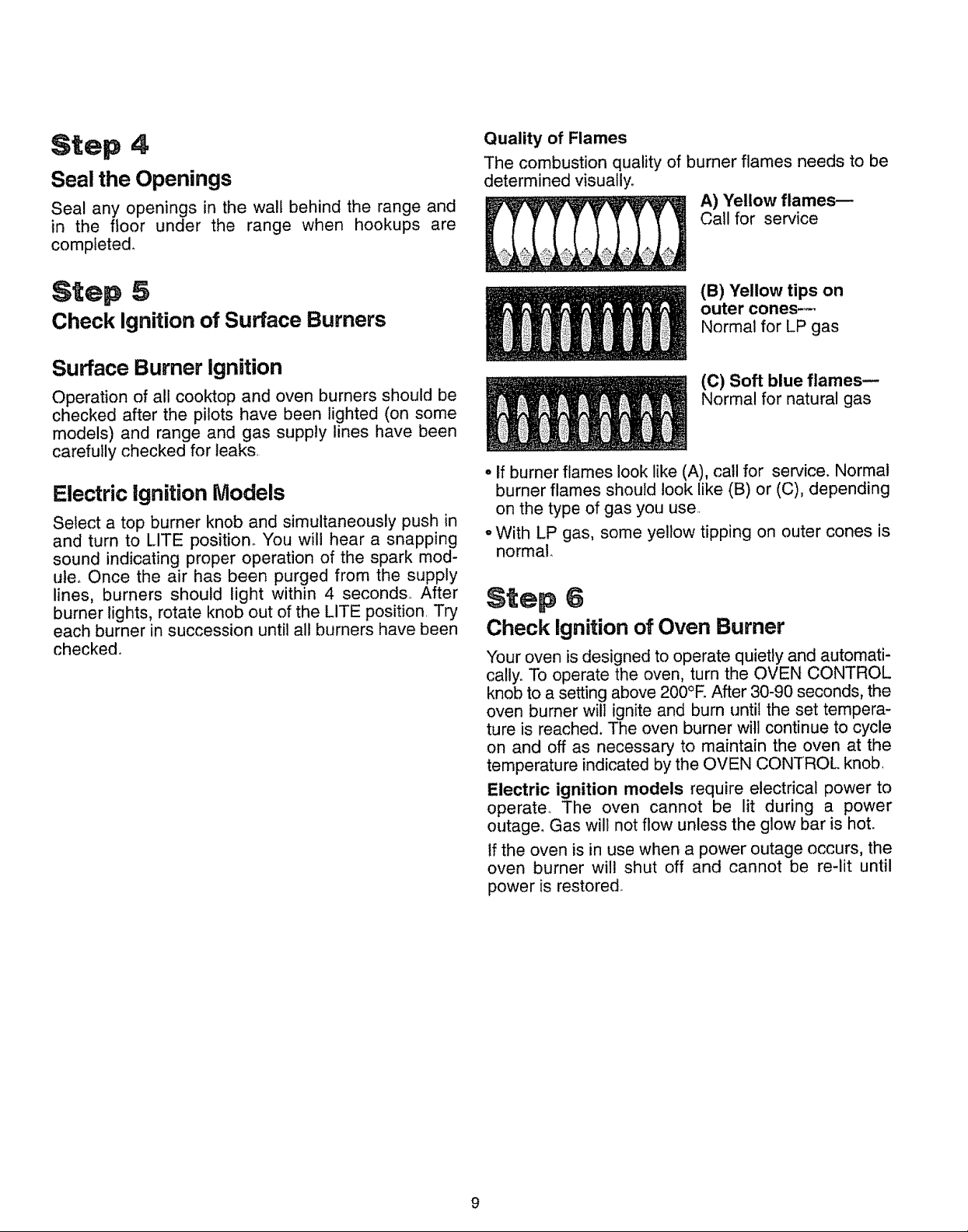
Quality of Flames
The combustion quality of burner flames needs to be
determined visually,
A) Yellow flames--
Call for service
Step 5
Check Ignition of Surface Burners
Surface Burner Ignition
Operation of all cooktop and oven burners should be
checked after the pilots have been lighted (on some
models) and range and gas supply lines have been
carefully checked for leaks,
Electric ignition Models
Select a top burner knob and simultaneously push in
and turn to LITE position. You will hear a snapping
sound indicating proper operation of the spark mod-
ute, Once the air has been purged from the supply
lines, burners should light within 4 seconds, After
burner lights, rotate knob out of the LITE position Try
each burner in succession until all burners have been
checked.
(B) "fellow tips on
outer cones---
Normal for LP gas
(C) Soft blue flames--
Normal for natural gas
• if burner flames look like (A), call for service. Normal
burner flames should look like (B) or (C), depending
on the type of gas you use
oWith LP gas, some yellow tipping on outer cones is
normal.
Step 6
Check Ignition of Oven Burner
Your oven is designed to operate quietly and automati-
cally. To operate the oven, turn the OVEN CONTROL
knob to a setting above 200°R After 30-90 seconds, the
oven burner will ignite and bum until the set tempera-
ture is reached. The oven burner witl continue to cycle
on and off as necessary to maintain the oven at the
temperature indicated by the OVEN CONTROL knob,
Electric ignition models require electrical power to
operate_ The oven cannot be lit during a power
outage. Gas will not flow unless the glow bar is hot.
if the oven is in use when a power outage occurs, the
oven burner will shut off and cannot be re-lit until
power is restored
9
RnstaURationInstructions (continued)
$tep 7
Adjust Broit and Oven Burner Air
Adjustment Shutters If Necessary
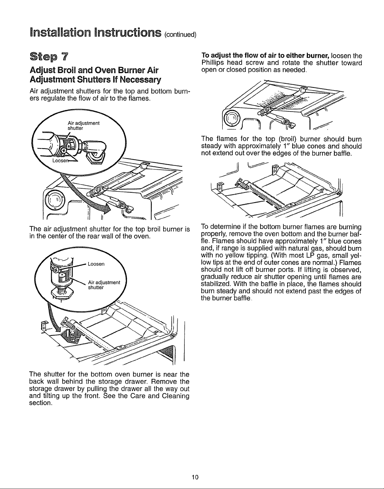
Air adjustment shutters for the top and bottom burn-
ers regulate the flow of air to the flame&
l
The air adjustment shutter for the top broil burner is
in the center of the rear wall of the oven.
To adjust the flow of air to either burner, loosen the
Phillips head screw and rotate the shutter toward
open or closed position as needed,
The flames for the top (broil) burner should burn
steady with approximately 1" blue cones and should
not extend out over the edges of the burner baffle.
To determine if the bottom burner flames are burning
properly, remove the oven bottom and the burner baf-
fle._ Flames should have approximately 1" blue cones
and, if range is supplied with natural gas, should burn
with no yellow tipping.. (With most LP gas, small yel-
low tips at the end of outer cones are normal.) Flames
should not lift off burner port& If lifting is observed,
gradually reduce air shutter opening until flames are
stabilized° With the baffle in place, the flames should
burn steady and should not extend past the edges of
the burner baffle
The shutter for the bottom oven burner is near the
back wall behind the storage drawer, Remove the
storage drawer by pulling the drawer all the way out
and tilting up the front. See the Care and Cleaning
section°
10
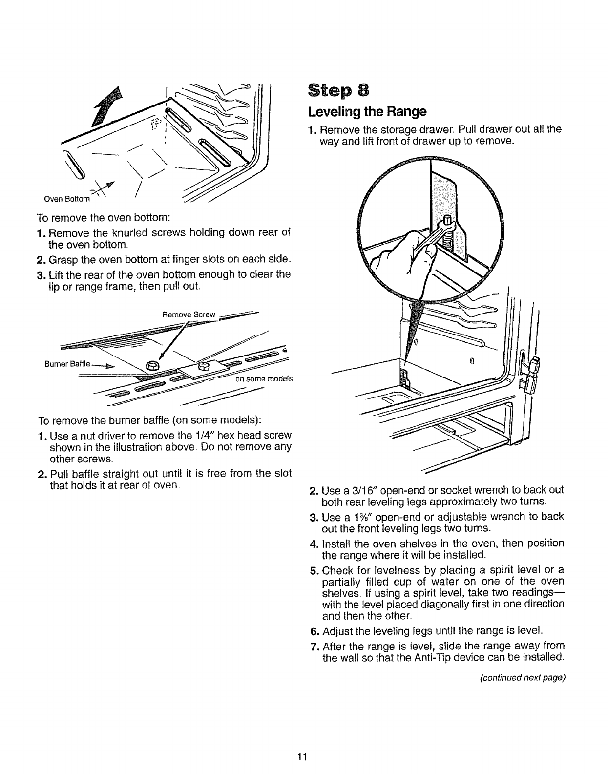
Oven Bottom
To remove the oven bottom:
1. Remove the knurled screws holding down rear of
the oven bottom.
2. Grasp the oven bottom at finger slots on each side°
3. Lift the rear of the oven bottom enough to clear the
lip or range frame, then pull out.
Remove Screw
Step 8
Leveling the Range
1. Remove the storage drawer_ Pull drawer out all the
way and lift front of drawer up to remove.
on some models
To remove the burner baffle (on some models):
1. Use a nut driver to remove the t/4" hex head screw
shown in the illustration above. Do not remove any
other screws.
2. Pull baffle straight out until it is free from the slot
that holds it at rear of oven_
2. Use a 3/16" open-end or socket wrench to back out
both rear leveling legs approximately two turns.
3. Use a t%" open-end or adjustable wrench to back
out the front leveling legs two turns.
4. Install the oven shelves in the oven, then position
the range where it will be installed.
5. Check for levelness by placing a spirit level or a
partially filled cup of water on one of the oven
shelves, if using a spirit level, take two readings--
with the level placed diagonally first in one direction
and then the other..
6. Adjust the leveling legs until the range is level_
7. After the range is level, slide the range away from
the wall so that the Anti-Tip device can be installed_
11
(continued next page)
mnstaaRationQnstructions (cont n ed)
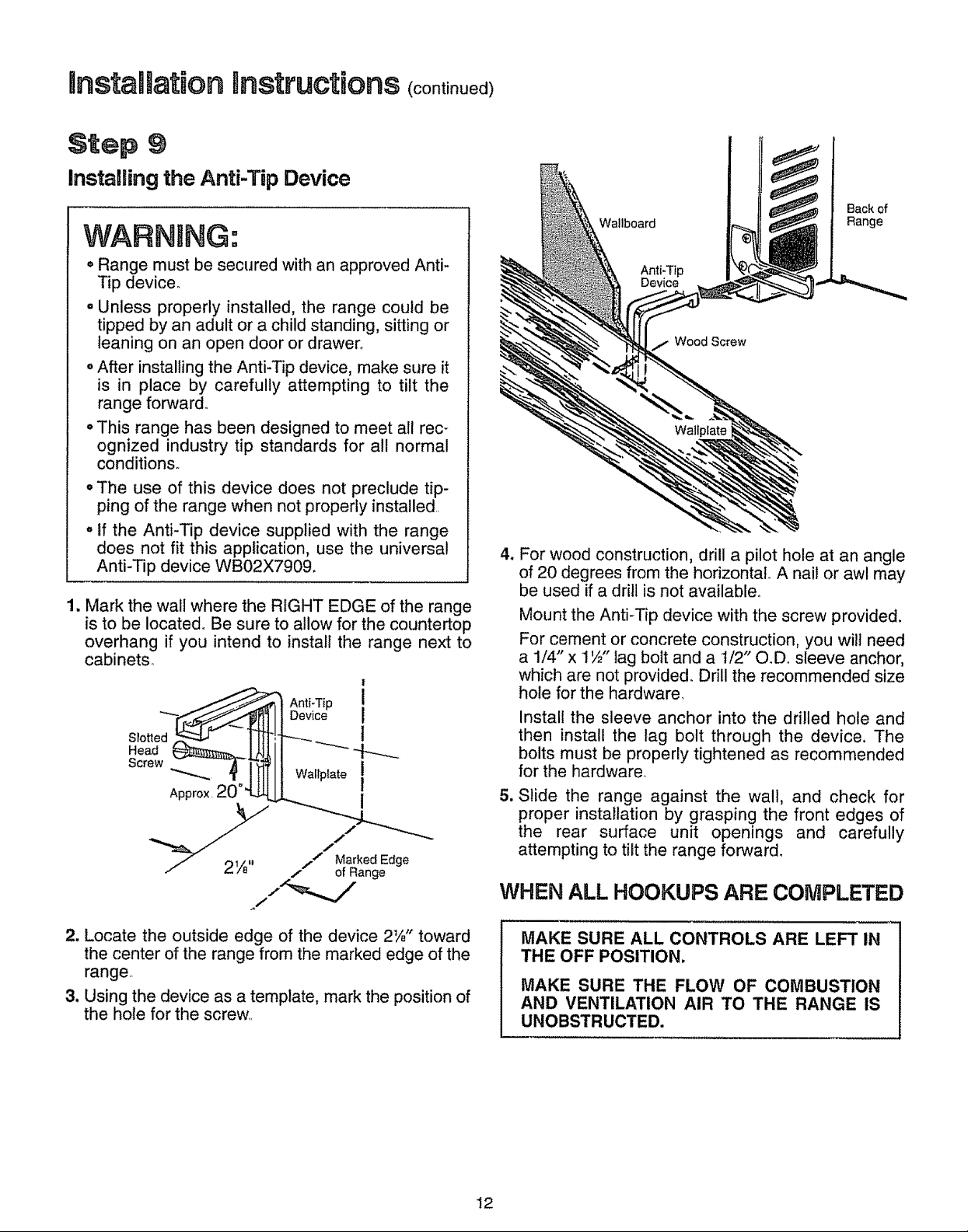
Step 9
Installing the Anti-Tap Device
WARNING:
Wallboard
Back of
Range
• Range must be secured with an approved Anti-
Tip device.
. Unless properly installed, the range could be
tipped by an adult or a child standing, sitting or
leaning on an open door or drawer_
• After installing the Anti-Tip device, make sure it
is in place by carefully attempting to tilt the
range forward,,
o This range has been designed to meet all rec-
ognized industry tip standards for all normal
condition&
oThe use of this device does not preclude tip-
ping of the range when not properly installed,,
. If the Anti-Tip device supplied with the range
does not fit this application, use the universal
Anti-Tip device WB02X7909.
1. Mark the wall where the RIGHT EDGE of the range
is to be located° Be sure to allow for the countertop
overhang if you intend to install the range next to
cabinets,,
!
Anti-Tip I
IOev ooI
/ 2W' / o"1_kaedeEdge
J
Anti-Tip
Device
Wood Screw
4_
For wood construction, drill a pilot hole at an angle
of 20 degrees from the horizontal. A nail or awl may
be used if a drill is not available°
Mount the Anti-Tip device with the screw provided.
For cement or concrete construction, you wilt need
a 1/4" x 1½" lag bolt and a 1/2" O.Do sleeve anchor,
which are not provided. Drill the recommended size
hole for the hardware,
Install the sleeve anchor into the drilled hole and
then install the lag bolt through the device. The
bolts must be properly tightened as recommended
for the hardware_
5_
Slide the range against the walt, and check for
proper installation by grasping the front edges of
the rear surface unit openings and carefully
attempting to tilt the range forward.
WHEN ALL HOOKUPS ARE COMPLETED
2. Locate the outside edge of the device 2W' toward
the center of the range from the marked edge of the
range
3. Using the device as a template, mark the position of
the hote for the screw
MAKE SURE ALL CONTROLS ARE LEFT IN
THE OFF POSITION.
MAKE SURE THE FLOW OF COMBUSTION
AND VENTILATION AIR TO THE RANGE IS
UNOBSTRUCTED.
12
How to Convert the Range for Usewith LP Gas or Natural Gas
Prepare Range for Conversion
Tools Required:
T_I 0 Torxdriver (for sealed burners)
CAUTION--Before converting the range:
(1) Turn off gas supply at the wall and
(2) Turn off the electrical power to the range.
If range has not yet been connected to gas supply,
or if flexible connection was made, range may be
pulled out from the wall to make conversion easier°
WARNING: Do not remove the pressure regulator from the range.
1/2" and 3/4" open-end wrench
Fiat blade screwdriver (small)
Nut drivers or wrenches: 7mm or 5/16"
(depending on the size of the spuds)
Step t
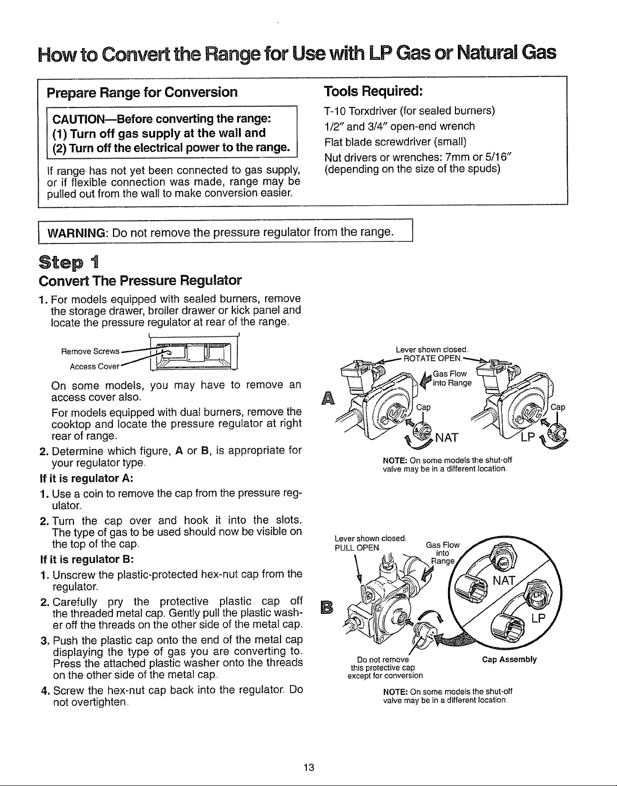
Convert The Pressure Regulator
1. For models equipped with sealed burners, remove
the storage drawer, broiler drawer or kick panel and
locate the pressure regulator at rear of the range_
Lever shown dosed,
On some models, you may have to remove an
access cover atsoo
For models equipped with dual burners, remove the
cooktop and locate the pressure regulator at right
rear of range.
2. Determine which figure, A or B, is appropriate for
your regulator type.
If it is regulator A:
1. Use a coin to remove the cap from the pressure reg-
ulatoro
2. Turn the cap over and hook it into the slots.
The type of gas to be used should now be visible on
the top of the cap
If it is regulator B:
1. Unscrew the plastic-protected hex-nut cap from the
regulator.
2. Carefully pry the protective plastic cap off
the threaded metal caF Gently pull the plastic wash-
er off the threads on the other side of the metal cap.
3. Push the plastic cap onto the end of the metal cap
displaying the type of gas you are converting to.
Press the attached plastic washer onto the threads
on the other side of the metal cap.
4. Screw the hex-nut cap back into the regulator_ Do
not overtighten.,
Lever shown closed,,
PULL OPEN.
\
B
Do not remove
this protective cap.
except for conversion
)Cap _tf ////,_"_lJ Cap
_NAT _JLP
NOTE: On some models the shut-off
vatve may be in a different location.
Gas Flow
into
Cap Assembly
NOTE: On some models the shut-off
valve may be in a different location
!3
Howto Convertthe Rangefor Usewith LPGasor NaturalGas oootJno )
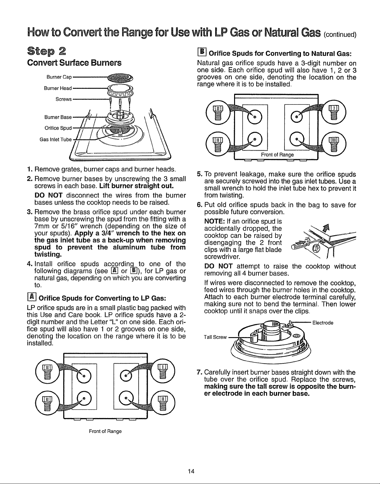
Step 2
Convert Surface Burners
Burner Cap
Burner Head
Screws
Burner Base
Orifice Spud
Gas Inlet Tube
1. Remove grates, burner caps and burner heads.
2. Remove burner bases by unscrewing the 3 small
screws in each base° Lift burner straight out.
DO NOT disconnect the wires from the burner
bases unless the cooktop needs to be raised.
3. Remove the brass orifice spud under each burner
base by unscrewing the spud from the fitting with a
7ram or 5/16" wrench (depending on the size of
your spuds)° Apply a 314" wrench to the hex on
the gas inlet tube as a back-up when removing
spud to prevent the aluminum tube from
twisting.
4. Install orifice spuds accordin_to one of the
following diagrams (see L_J or LBJ), for LP gas or
natural gas, depending on which you are converting
to.
[_ Orifice Spuds for Converting to LP Gas:
LP orifice spuds are in a small plastic bag packed with
this Use and Care book LP orifice spuds have a 2-
digit number and the Letter "L" on one side. Each ori-
fice spud will also have 1 or 2 grooves on one side,
denoting the location on the range where it is to be
installed.
Orifice Spuds for Converting to Natural Gas:
Natural gas orifice spuds have a 3-digit number on
one side° Each orifice spud will also have t, 2 or 3
grooves on one side, denoting the location on the
range where it isto be installed°
Front of Range
w
To prevent leakage, make sure the orifice spuds
are securely screwed into the gas inlet tubes. Use a
small wrench to hold the inlet tube hex to prevent it
from twisting.
=
Put old orifice spuds back in the bag to save for
possible future conversion_
NOTE: If an orifice spud is
accidentally dropped, the
cooktop can be raised by
disengaging the 2 front
clips with a large flat blade
screwdriver.
DO NOT attempt to raise the cooktop without
removing all 4 burner bases.
If wires were disconnected to remove the cooktop,
feed wires through the burner holes in the cooktop.
Attach to each burner electrode terminal carefully,
making sure not to bend the terminal Then lower
cooktop until it snaps over the clips
| a i
v
A
%- -
....... _._11 i //i J_._j_--3_._ ///
Front of Range
7. Carefully insert burner bases straight down with the
tube over the orifice spud. Replace the screws,
making sure the tall screw is opposite the burn-
er electrode in each burner base.
t4
Step :3
Step 5
Converting Surface Burners on Models
Equipped with Dual Burners (See
Step 2 if range is equipped with sealed
burners.)
1. Lift cooktop.
2, Lift burner assem-
blies straight up and
set aside to gain
access to surface
burner spuds
3. With a 7ram or 5/16"
wrench (depending
on the size of your
spuds), remove each
of the four spuds on
the surface burner
gas inlet tubes and replace them with the correct gas
spuds mounted in a holder at the right rear of the
range, above the regulator. Natural gas spuds are
brass and LP gas spuds are red or silver (Mount the
spuds that you removed from the inlet tubes back in
the holder..) To prevent leakage, make sure spuds
are securely screwed into gas inlet tubes.
4. Replace the burner assemblies.
5. Keep all spuds with your range so you have them if
you move or get a different gas hook-up.
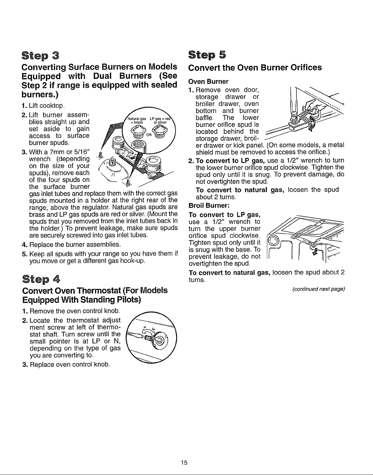
Step 4
Convert Oven Thermostat (For Models
Equipped With Standing Pilots)
1. Remove the oven control knob,,
2, Locate the thermostat adjust
ment screw at left of thermo-
stat shaft° Turn screw until the
small pointer is at LP or N,
depending on the type of gas
you are converting to.
3. Replace oven control knob,
Convert the Oven Burner Orifices
Oven Burner
I. Remove oven door,
storage drawer or
broiler drawer, oven
bottom and burner
baffler The lower
burner orifice spud is
located behind the
storage drawer, broil-
er drawer or kick panel. (On some models, a metal
shield must be removed to access the orifice.)
2. To convert to LP gas, use a 1/2" wrench to turn
the lower burner orifice spud clockwise. Tighten the
spud only until it is snug. To prevent damage, do
not overtighten the spud°
To convert to natural gas, loosen the spud
about 2 turns.
Broil Burner:
To convert to LP gas,
use a 1/2" wrench to
turn the upper burner
orifice spud clockwise.
Tighten spud only until it
is snug with the base° To
prevent leakage, do not
overtighten the spud.
To convert to natural gas, loosen the spud about 2
turns.
(continued next page)
!5
 Loading...