

Page 1

KENMORE ELECTRIC WALL OVEN INSTALLATION INSTRUCTIONS
27 3/16”
(69.1 cm)
1¼”
(3.2 cm)
Min.
31”*
(78.7 cm)
3”
(7.6 cm)
1” (2.5 cm)
Min.
(and Optional Electric or Gas Cooktop Combination)
INSTALLATION AND SERVICE MUST BE PERFORMED BY A QUALIFIED INSTALLER.
IMPORTANT: SAVE FOR LOCAL ELECTRICAL INSPECTOR'S USE.
READ AND SAVE THESE INSTRUCTIONS FOR FUTURE REFERENCE.
FOR YOUR SAFETY: Do not store or use gasoline or other flammable vapors and liquids in
the vicinity of this or any other appliance.
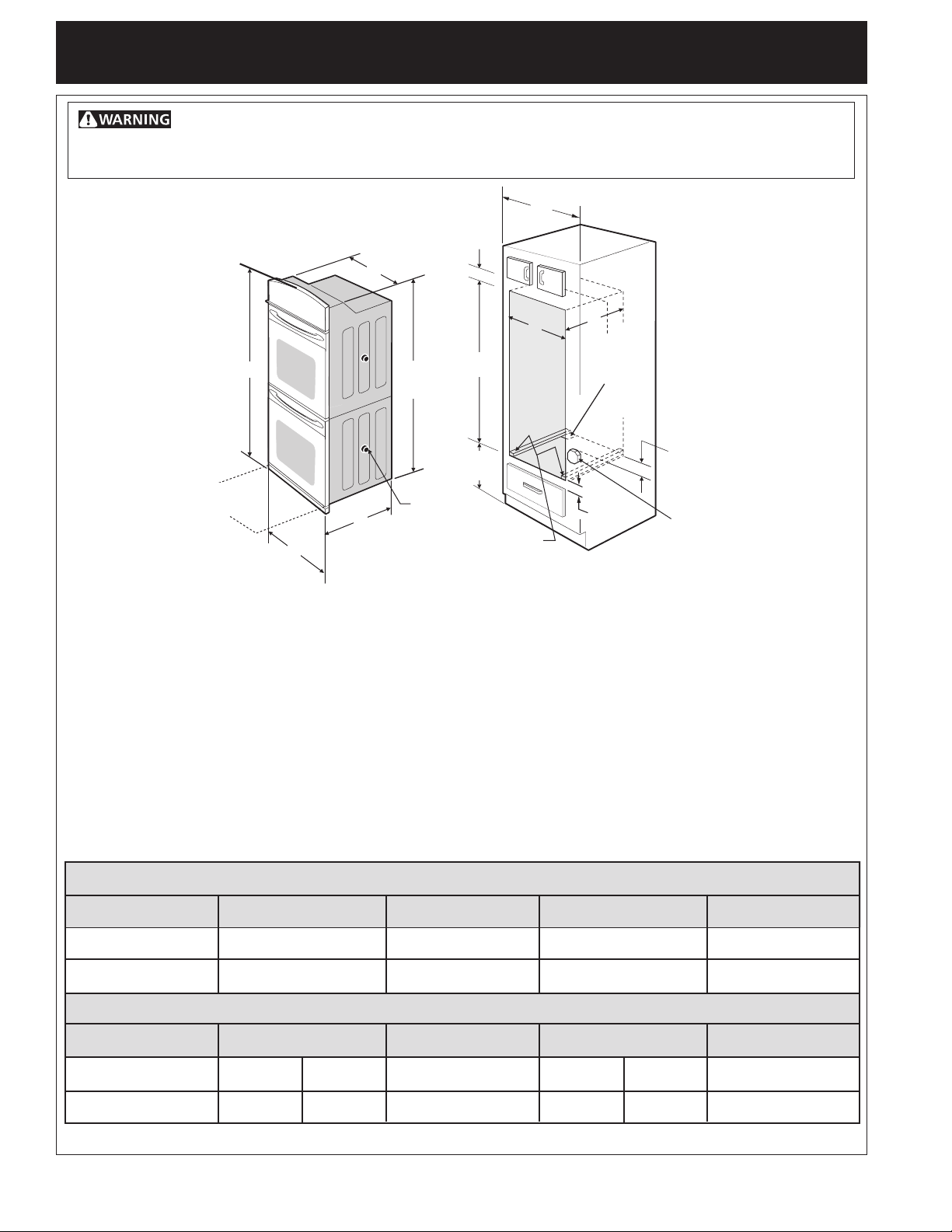
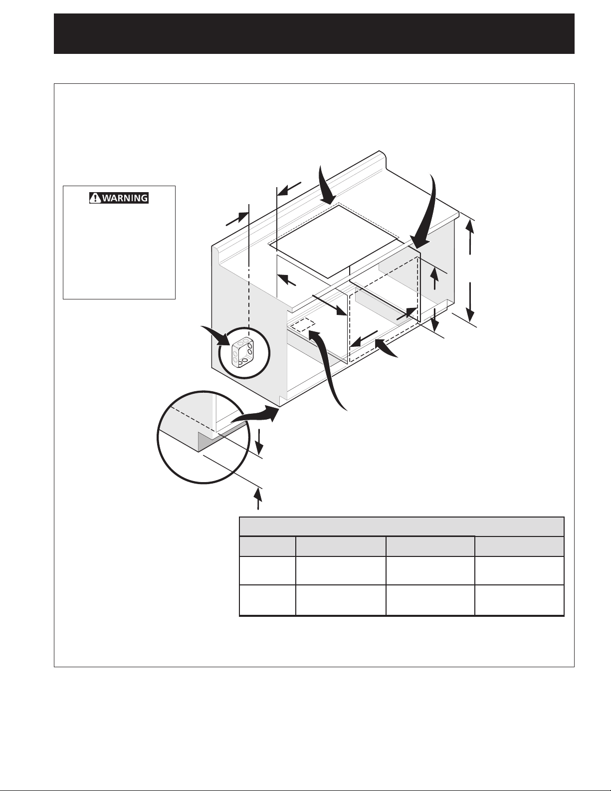
Your new wall oven has been designed to fit a limited variety of cutout sizes to make the job of installing
easier. The first step of your installation should be to measure your current cutout dimensions and
compare them to the cutout dimensions chart below for your model. You may find little or no cabinet
work being necessary.
Do not remove spacers (if equipped) on the side walls and/or on the back of the built-in
oven. These spacers center the oven in the space provided. The oven must be centered to prevent
excess heat buildup that may result in heat damage or fire.
NOTES:
1. Base must be capable of supporting 150 pounds (68 kg) for 27" models and
200 pounds (90 kg) for 30" models.
2. Allow at least 21" (53.3 cm) clearance in front of oven for door
depth when it is open.
3. Dimension G (cutout depth) is critical to
the proper installation of the built-in
oven. If the oven decorative trim does
not butt against the cabinet, or if noise
is heard on convection models, verify
B
dimension G to assure it is the required
depth.
4. For a cutout height greater than
2713/16" (70.6 cm) add one 2"
(5 cm) wide wood shim of
appropriate height to each side
Door Open
(see note 2)
D
of the opening under the
appliance side rails.
A
* Suggested distance from floor is 31" (78.7 cm).
Minimum required distance is 4 ½" (11.4 cm)
Figure 1
27" and 30" Single Wall Ovens (Double ovens see Figure 2)
1” (2.5 cm)
Min.
C
H
27 3/16”
(69.1 cm)
31”*
(78.7 cm)
Spacer
2" (5 cm) Wide Wood
Spacer if Needed
I
G
Hole for
Cable
F
3”
(7.6 cm)
1¼”
(3.2 cm)
Min.
Electrical
Junction Box
MODEL
27" (68.6 cm) Wall Oven
30" (76.2 cm) Wall Oven
MODEL
27" (68.6 cm) Wall Oven
30" (76.2 cm) Wall Oven
All dimensions are in inches (cm).
Printed in United States
24
28½ (72.4)
A
27 (68.6)
30 (76.2)
CUTOUT DIMENSIONS AND CABINET WIDTH
Min. F Max.
7
/8 (63.2)
25¼ (64.1)
29 (73.7)
PRODUCT DIMENSIONS
B
291/16 (73.8)
1
/16 (73.8)
29
G (Min.)
23½ (59.7)
23½ (59.7)
1
C
245/8 (62.5)
28¼ (71.8)
Min. H Max.
27¼ (69.2)
27¼ (69.2)
28½ (72.4)
28½ (72.4)
D
24½ (62.2)
24½ (62.2)
I
271/8 (68.9) Min
1
/8 (76.5) Min
30
P/N 318201516 (0610) Rev. E
English – pages 1-10
Page 2
KENMORE ELECTRIC WALL OVEN INSTALLATION INSTRUCTIONS
48 5/8”
(123.5 cm)
11½”
(29.2 cm)
1¼”
(3.2 cm)
Min.
3” (7.6 cm)
Max.
1” (2.5 cm)
Min.
(and Optional Electric or Gas Cooktop Combination)
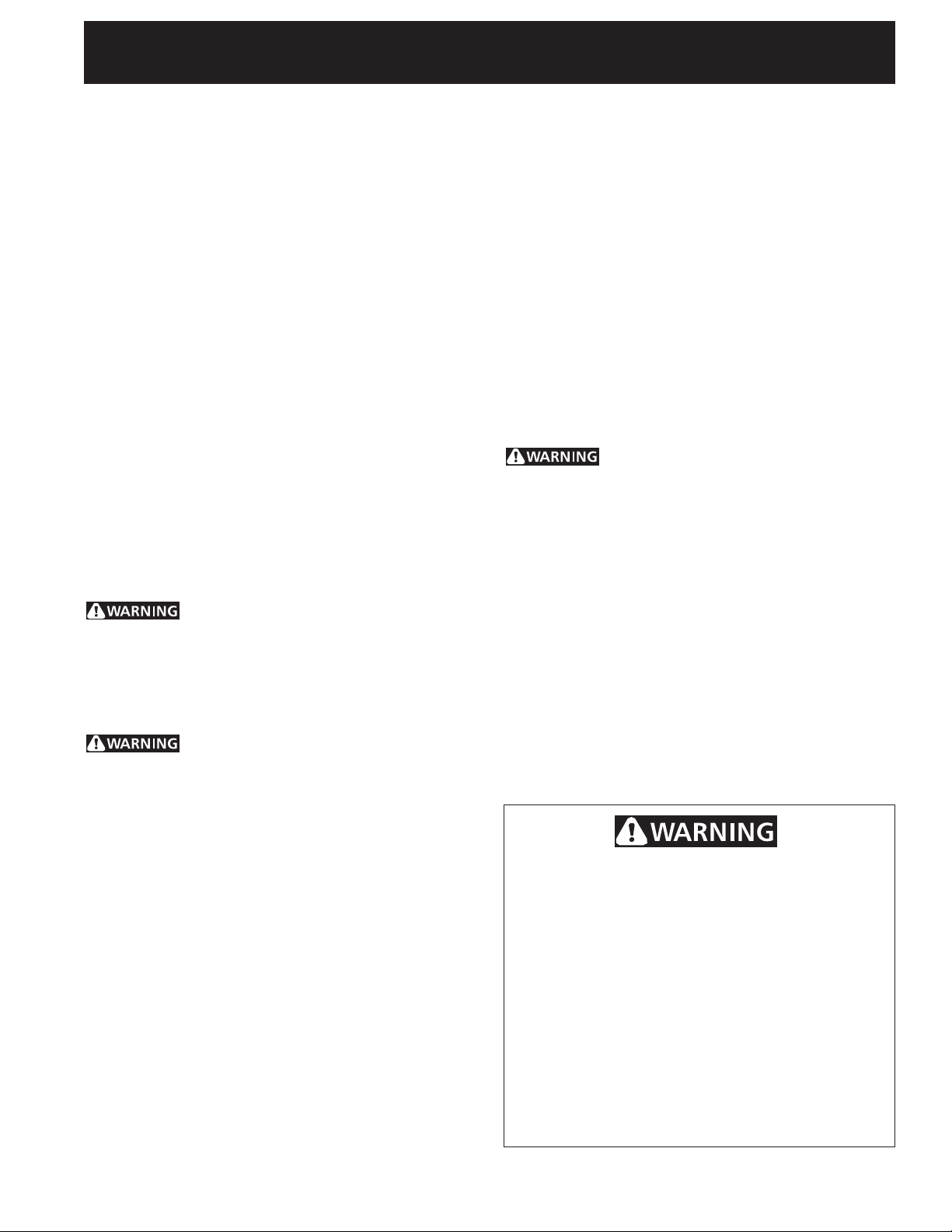
Do not remove spacers (if equipped) on the side walls and/or on the back of the built-in
oven. These spacers center the oven in the space provided. The oven must be centered to prevent
excess heat buildup that may result in heat damage or fire.
C
B
Door Open
(see note 2)
48 5/8”
(123.5 cm)
Spacer
D
A
2" (5 cm) Wide Wood
NOTES:
1. Base must be capable of supporting 300 pounds
(136 kg) for 27" models and 375 pounds (170 kg)
for 30" models.
2. Allow at least 21" (53.3 cm) clearance in front of
oven for door depth when it is open.
3. Dimension G (cutout depth) is critical to the proper
installation of the built-in oven. If the oven
decorative trim does not butt against the cabinet, or
if noise is heard on convection models, verify
dimension G to assure it is according to the required
dimension.
27" AND 30" DOUBLE OVENS (Single Ovens see Figure 1)
1” (2.5 cm)
Min.
H
11½”
(29.2 cm)
Spacer if Needed
4. For a cutout height greater than 49¼" (125.1 cm)
add a 2" (5 cm) wide wood shim of appropriate
height to each side of the opening under the
appliance side rails.
Figure 2
I
F
G
Hole for
Cable
1¼”
(3.2 cm)
Min.
3” (7.6 cm)
Max.
Electrical
Junction Box
MODEL
27" (68.6 cm) Wall Oven
30" (76.2 cm) Wall Oven
MODEL
27" (68.6 cm) Wall Oven
30" (76.2 cm) Wall Oven
All dimensions are in inches (cm).
Min. F Max.
7
24
/8 (63.2)
28½ (72.4)
A
27 (68.6)
30 (76.2)
PRODUCT DIMENSIONS
B
50½ (128.3)
50½ (128.3)
CUTOUT DIMENSIONS AND CABINET WIDTH
G (Min.)
25¼ (64.1)
29 (73.7)
23½ (59.7)
23½ (59.7)
2
C
245/8 (62.5)
28¼ (71.8)
Min. H Max.
7
48
/8 (124.1)
7
/8 (124.1)
48
7
49
/8 (126.7)
7
/8 (126.7)*
49
D
24½ (62.2)
24½ (62.2)
I
271/8 (68.9) Min
1
/8 (76.5) Min
30
Page 3
KENMORE ELECTRIC WALL OVEN INSTALLATION INSTRUCTIONS
(and Optional Electric or Gas Cooktop Combination)
Important Notes to the Installer
1. Read all instructions contained in these installation
instructions before installing the wall oven.
2. Remove all packing material from the oven
compartments before connecting the electrical supply
to the wall oven.
3. Observe all governing codes and ordinances.
4. Be sure to leave these instructions with the consumer.
5. Oven door may be removed to facilitate installation.
6. THESE OVENS ARE NOT APPROVED FOR
STACKABLE OR SIDE-BY-SIDE INSTALLATION.
Important Note to the Consumer
Keep these instructions with your Owner's Guide for future
reference.
IMPORTANT SAFETY
INSTRUCTIONS
• Be sure your wall oven is installed and grounded
properly by a qualified installer or service
technician.
• This wall oven must be electrically grounded in
accordance with local codes or, in their absence,
with the National Electrical Code CSA Standard
C22.1, Canadian Electrical Code, Part 1, in Canada.
Stepping, leaning or sitting on the
door of this wall oven can result in serious injuries
and can also cause damage to the wall oven.
• Never use your wall oven for warming or heating
the room. Prolonged use of the wall oven without
adequate ventilation can be dangerous.
The electrical power to the oven must
be shut off while line connections are being made.
Failure to do so could result in serious injury or
death.
(time-delay fuse or circuit breaker is recommended).
DO NOT fuse neutral. The fuse size must not exceed
the circuit rating of the appliance specified on the
nameplate. Only certain cooktop models may be
installed over certain built-in electric oven models.
Approved cooktops and built-in ovens are listed by
the MFG ID number (see the insert sheet included in
the literature package).
2. The single wall oven can consume up to 4000W at
240Vac; use a circuit breaker of 30 Amp with wire
gauge #8 AWG. The double wall oven can consume
up to 8000W at 240Vac; use a circuit breaker of 40
Amp with wire gauge #8 AWG.
NOTE: Wire sizes and connections must conform with
the fuse size and rating of the appliance in accordance
with the American National Electrical Code CSA
Standard C22.1, Canadian Electrical Code, Part 1, and
local codes and ordinances.
An extension cord should not be used
with this appliance. Such use may result in a fire,
electrical shock, or other personal injury. If you need
a longer power cord you can order for purchase a 10'
(3 m) power cord kit #903056-9010 by calling the Sears
Service Center.
3. These appliances should be connected to the fused
disconnect (or circuit breaker) box through flexible
armored or nonmetallic sheathed cable. The flexible
armored cable extending from the appliance should
be connected directly to the junction box. The
junction box should be located as shown in Figure 1
or Figure 2 and with as much slack as possible
remaining in the cable between the box and the
appliance, so it can be moved if servicing is ever
necessary.
4. A suitable strain relief must be provided to attach
the flexible armored cable to the junction box.
1. Carpentry
Refer to figure 1 or 2 for the dimensions applicable to
your appliance, and the space necessary to receive the
oven. The oven support surface may be solid plywood or
similar material, however the surface must be level from
side to side and from front to rear.
2. Electrical Requirements
This appliance must be supplied with the proper voltage
and frequency, and connected to an individual, properly
grounded branch circuit, protected by a circuit breaker or
fuse, having amperage as noted on the rating plate (the
rating plate is located on the side trim.
Observe all governing codes and local ordinances
1. A 3-wire or 4-wire single phase 120/240 or 120/208
Volt, 60 Hz AC only electrical supply is required on
a separate circuit fused on both sides of the line
Electrical Shock Hazard
• Electrical ground is required on this appliance.
• Do not connect to the electrical supply until
appliance is permanently grounded.
• Disconnect power to the junction box before
making the electrical connection.
• This appliance must be connected to a
grounded, metallic, permanent wiring system,
or a grounding connector should be connected
to the grounding terminal or wire lead on the
appliance.
• Do not use a gas supply line for grounding the
appliance.
Failure to do any of the above could result in a
fire, personal injury or electrical shock.
3
Page 4
KENMORE ELECTRIC WALL OVEN INSTALLATION INSTRUCTIONS
(and Optional Electric or Gas Cooktop Combination)
In cold weather shipping and storage
conditions, make sure that oven is in final location at
least three (3) hours before switching on power.
Switching on power while oven is still cold may damage
the oven controls.
Model and Serial Number Location
The serial plate is located along the interior side trim of
the oven and visible when the door is opened.
When ordering parts for or making inquires about your
oven, always be sure to include the model and serial
numbers and a lot number or letter from the serial plate
on your oven.
Single Wall Oven
Serial Plate Location
These appliances are equipped with a copper conductor
flexible cable. If connection is made to aluminum house
wiring, use only special connectors which are approved
for joining copper and aluminum wires in accordance
with National Electrical Code and local codes and
ordinances.
These appliances are manufactured with a white neutral
power supply wire and a frame connected green or bare
copper grounding wire.
Where local codes permit connecting the appliancegrounding conductor to the neutral (white) wire
(see figure 3):
1. Disconnect the power supply.
2. In the circuit breaker, fuse box or junction box:
connect appliance and power supply cable wires as
shown in Figure 3.
Cable from Power Supply
White Wire
(Neutral)
Black
Wires
Red
Wires
Double Wall Oven
Serial Plate Location
3. Adjusting Oven Height
Oven height can be adjusted with 2" (5 cm) wide wood
shims when needed to fit into an existing cabinet cutout
opening, when cutout height exceeds 27
for the single wall oven or 49¼"
(125.1 cm) for the
13
/
"
(70.6 cm)
16
double wall oven (see Figure 1 or 2). Place shims of
appropriate height beneath the oven side rails.
4. Electrical connection
It is the responsibility and obligation of the consumer to
contact a qualified installer to assure that the electrical
installation is adequate and is in conformance with the
National Electrical Code CSA Standard C22.1, Canadian
Electrical Code, Part 1, and local codes and ordinances.
Electrical ground is required on this appliance.
Junction
Box
White Wire
(Neutral)
Ground Wire
(Bare or Green Wire)
U.L.-Listed Conduit
Connector (or CSA listed)
Cable from appliance
Figure 3
3-WIRE GROUNDED JUNCTION BOX
Improper connection of aluminum
house wiring to copper leads can result in a short
circuit or fire. Use only connectors designed for
joining copper to aluminum, and follow the
manufacturer's recommended procedure closely.
You may not ground the oven
through the neutral (white) wire if oven is used in
a new branch circuit installation (1996 NEC), mobile
home, recreational vehicle, or where local codes do
not permit grounding through the neutral (white)
wire. When grounding through the neutral (white)
wire is prohibited, you must use a 4-wire power
supply cable. See Figure 4. Failure to heed this
warning may result in electrocution or other
serious personal injury.
4
Page 5
KENMORE ELECTRIC WALL OVEN INSTALLATION INSTRUCTIONS
See addendum for anti-tip screws installation
at the end of this booklet (if necessary).
(and Optional Electric or Gas Cooktop Combination)
If oven is used in a new branch circuit installation
(1996 NEC), mobile home, recreational vehicle, or
where local codes DO NOT permit grounding
through the neutral (white) wire (see figure 4):
1. Disconnect the power supply.
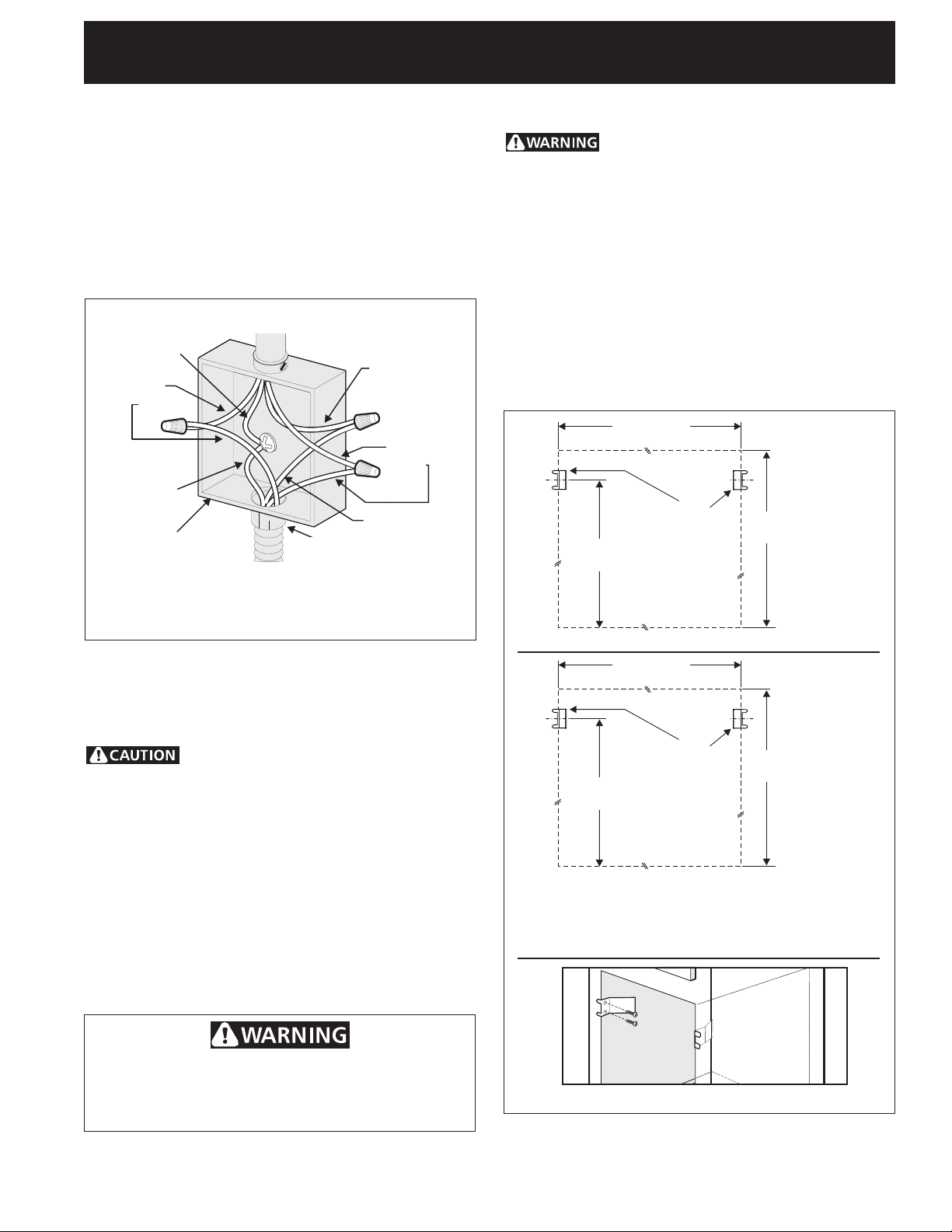
2. Separate the green (or bare copper) and white
appliance cable wires.
3. In the circuit breaker, fuse box or junction box:
connect appliance and power supply cable wires as
shown in Figure 4.
Cable from Power Supply
Ground Wire
White Wire
Red
Wires
Black
Wires
Ground Wire
(Bare or Green
Wire)
Junction Box
U.L.-Listed Conduit
White Wire
Connector (or CSA listed)
Cable from appliance
Figure 4
4-WIRE GROUNDED JUNCTION BOX
DO NOT ground to a gas supply pipe. DO NOT connect
to electrical power supply until appliance is permanently
grounded. Connect the ground wire before turning on
the power (Figure 4).
5. Cabinet Installation
The wall oven can tip when the door is
open. The mounting brackets supplied with the
wall oven must be attached to the cabinet and the
appliance to prevent tipping of the wall oven and
injury to persons.
Mounting Brackets Installation Instructions
1. Unpack the wall oven. Remove the bottom trim taped
on the oven side panel. Find the 2 mounting brackets
and screws included in the literature package.
2. Install the mounting brackets in the wall cabinet as
shown on Figure 5. Note: To prevent damage to
cabinet, it is recommended to drill 1/16" (0.16 cm) dia.
pilot holes before installing the mounting brackets.
F see figure 1
Mounting
Brackets
22 3/16" *
(56.4 cm)
Single Wall ovens
F see figure 2
H
see figure 1
If connecting to a 4-wire electrical
system (mobile homes), the appliance frame MUST
NOT be connected to the neutral wire of the 4-wire
electrical system.
NOTE TO ELECTRICIAN: The armored cable leads
supplied with the appliance are UL-recognized for
connection to larger gauge household wiring. The
insulation of the leads is rated at temperatures much
higher than temperature rating of household wiring. The
current carrying capacity of the conductor is governed by
the temperature rating of the insulation around the wire,
rather than the wire gauge alone.
Heavy Weight Hazard
• Use 2 or more people to move and install wall oven.
• Failure to follow this instruction can result in injury
or damage to the unit.
Mounting
Brackets
43 5/8" *
(110.8 cm)
H
see figure 2
Double Wall ovens
* If wood shims are installed please calculate this
dimension from the top of the shim to the middle of
the mounting bracket.
Figure 5
5
Page 6

KENMORE ELECTRIC WALL OVEN INSTALLATION INSTRUCTIONS
(and Optional Electric or Gas Cooktop Combination)
IMPORTANT
Oven
Mounting
bracket installed
1
in cabinet
Cabinet
Right
Side
Tool
supplied
2
Mounting
bracket
released
Hole where to
insert the tool
Do not lift the oven by the door handle.
3.Insert the oven into the cabinet opening. Slide oven
inward leaving 1½" (3.8 cm) clearance between the oven
and front of cabinet (see Figure 6). Pull the armored cable
through the hole for it in the cabinet and toward the
junction box while moving the appliance inward.
Oven
side
trim
3
Oven removed
from the cabinet
1½" (3.8 cm)
clearance
between unit
Figure 6
4.Push the oven in and against the cabinet; the oven side
bracket will clip into the mounting bracket installed into
the side of cabinet.
To pull out the oven for servicing you must use the two
tools supplied with the oven. Insert one tool into hole in
each side of oven frame. Holes are visible when door is
opened. After inserting tools pull the oven towards you
(see Figure 7).
5.Bottom Trim Installation:
Place the top of the bottom trim over the side trim tabs
on each side of the oven below the oven door and fix it
using the 2 screws supplied in the mounting holes
located on each side trim below the oven frame (see
figure 8).
Screws
supplied
Figure 7
Bottom Trim
Figure 8
6
Page 7
KENMORE ELECTRIC WALL OVEN INSTALLATION INSTRUCTIONS
(and Optional Electric or Gas Cooktop Combination)
6.For typical under counter installation of an electric built-in oven see Figure 9 below.
Only certain cooktop models may be installed over certain built-in electric oven models. Approved cooktops
and built-in ovens are listed by the MFG ID number and
product code (see the insert sheet included in the literature package and cooktop installation instructions for the
dimensions).
To reduce the risk of
personal injury and
tipping of the wall
oven, the wall oven
must be secured to
the cabinet (s) by
mounting brackets.
208/240 Volt junction box
for built-in oven.
Approx. 3”
(7.5 cm)
Cabinet side filler panels are
necessary to isolate the unit
from adjoining cabinets. Cabinet
side filler height should allow for
installation of approved cooktop
models
36” Min.
(91.4 cm) Min.
G
H
F
Use 3/4” (1.9 cm) plywood, installed on
two runners, flush with toe plate. Base
must be capable of supporting 150
pounds (68 kg) for 27" models and 200
pounds (90 kg) for 30" models.
* If no cooktop is installed directly over
the oven unit, 5” (12.7 cm) maximum
is allowed above the floor.
Figure 9 - TYPICAL UNDER COUNTER INSTALLATION OF A SINGLE ELECTRIC BUILT-IN OVEN
WITH AN ELECTRIC COOKTOP MOUNTED ABOVE
4 1/2” (11.5 cm) Max.*
F.WIDTH G.DEPTH
27" (68.6 cm)
Wall Oven
30" (76.2 cm)
Wall Oven
247/8" (63.2 cm) Min.
25¼" (64.1 cm) Max.
28½" (72.4 cm) Min.
29" (73.7 cm) Max.
Cut an opening in wood base minimum 9” x 9”
(23 X 23 cm), 2” (5 cm) from left side filler
panel, to route armoured cable to junction box.
CUTOUT DIMENSIONS
H.HEIGHT
23½" (59.7 cm) Min.
23½" (59.7 cm) Min.
27¼" (69.2 cm) Min.
28½" (72.4 cm) Max.
27¼" (69.2 cm) Min.
28½" (72.4 cm) Max.
7
Page 8

KENMORE ELECTRIC WALL OVEN INSTALLATION INSTRUCTIONS
(and Optional Electric or Gas Cooktop Combination)
18”(45.7 cm) Max.
Flexible Appliance Conduit
Wall Oven Cabinet
Figure 10 - TYPICAL UNDER COUNTER INSTALLATION OF A SINGLE ELECTRIC BUILT-IN OVEN
Cabinet sides or
filler panel
WITH A GAS COOKTOP ABOVE
Flare
Union
5” Max.
(12.7 cm)
6 1/2” Min.
(16.5 cm)
Flare
Union
120V/60Hz
Grounded
Outlet
Pressure Regulator
Manual
Shutoff
Valve
4”(10 cm)
Right Side of
Cabinet
(To be
accessible for
shut-off
valve
operation)
8
Page 9

KENMORE ELECTRIC WALL OVEN INSTALLATION INSTRUCTIONS
(and Optional Electric or Gas Cooktop Combination)
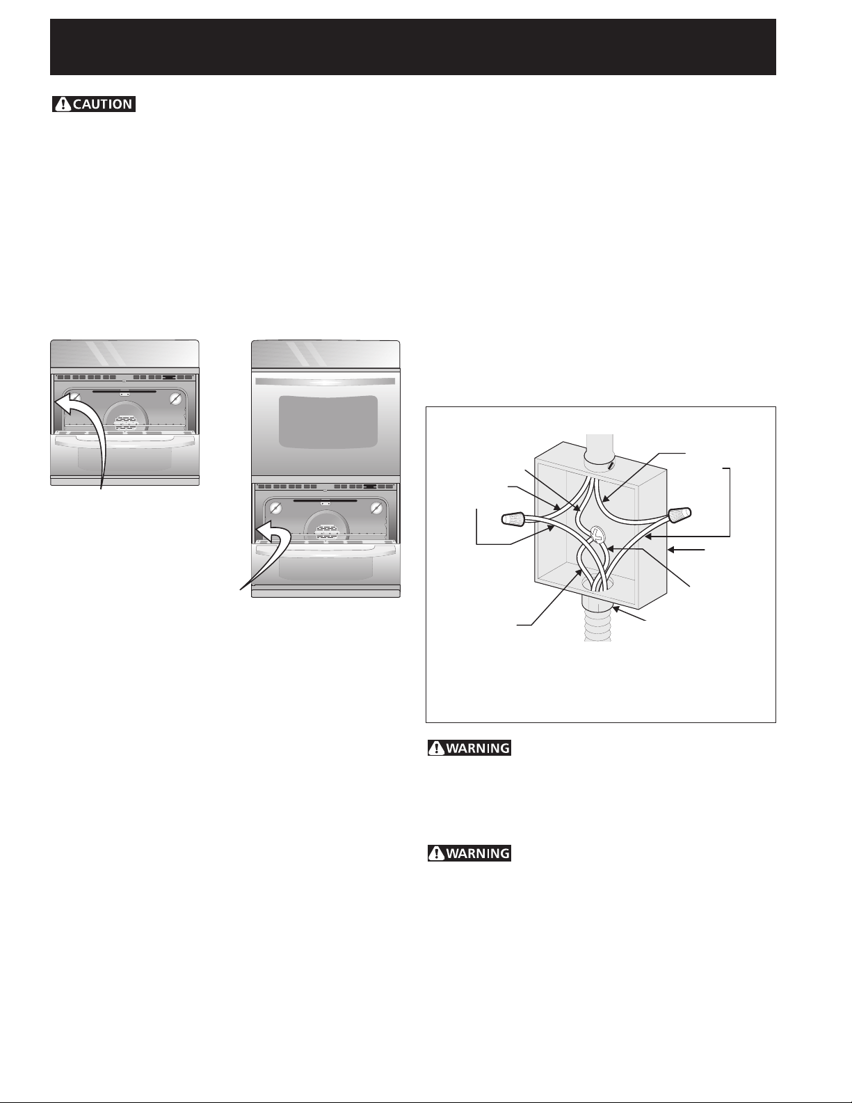
6. Leveling the Wall Oven
1. Install an oven rack in the center of the upper oven
(see Figure 11).
2. Place a level on the rack. Take 2 readings with the
level placed diagonally in one direction and then the
other. Use wood shims under the wall oven to level
if necessary.
3. Repeat in the lower oven if you have a double cavity
wall oven. If the level indicates that the rack is not
level, use wood shims to reach a compromise for
both ovens.
Figure 11
IMPORTANT NOTE
A cooling fan inside the upper rear part
above the oven (some models) provides
cooling of the oven electrical and
electronic components. If the oven has
been operating at high temperatures, the
fan will continue to run after the oven is
turned off.
7. Checking Operation
Your model is equipped with an Electronic Oven
Control. Each of the functions has been factory checked
before shipping. However, it is suggested that you verify
the operation of the electronic oven controls once more.
Refer to the Use and Care Guide for operation.
1. Remove all items from the inside of the oven.
2. Turn on the power to the oven (Refer to your Use &
Care Guide.)
3. Verify the operation of the electronic oven controls:
Bake - Verify that this function makes the oven hot.
20 seconds after turning oven on, open the door and
you should feel heat coming from the oven.
Broil - When the oven is set to BROIL, the upper
element in the oven should become red.
Convection (some models )–When the oven is set
for a convection baking or roasting, both elements
cycle on and off alternately and the convection fan
will run. The convection fan will stop running when
the oven door is opened.
Before You Call for Service
Read the Before You Call for Service Checklist and
operating instructions in your Use and Care Guide. It
may save you time and expense. The list includes
common occurrences that are not the result of defective
workmanship or materials in this appliance.
Refer to your Use and Care Guide for Sears service
phone numbers.
9
Page 10

KENMORE ELECTRIC WALL OVEN INSTALLATION INSTRUCTIONS
(and Optional Electric or Gas Cooktop Combination)
NOTES:
10
Page 11

INSTRUCTIONS D'INSTALLATION POUR FOUR ENCASTRÉ ÉLECTRIQUE
27 3/16”
(69.1 cm)
1¼”
(3.2 cm)
Min.
31”*
(78.7 cm)
3”
(7.6 cm)
1” (2.5 cm)
Min.
(Combiné à une table de cuisson électrique ou à gaz (en option))
L’INSTALLATION ET L’ENTRETIEN DOIVENT ÊTRE EFFECTUÉS PAR UN INSTALLATEUR
QUALIFIÉ. IMPORTANT : CONSERVEZ POUR L’INSPECTEUR D’ÉLECTRICITÉ LOCAL.
LISEZ ET CONSERVEZ CES INSTRUCTIONS POUR RÉFÉRENCES ULTÉRIEURES.
POUR VOTRE SÉCURITÉ : N’entreposez pas ou n’utilisez pas d’essence ou d’autres produits
inflammables à proximité de cet appareil ou de tout autre appareil électroménager.
La première étape de votre installation consiste à mesurer les dimensions du découpage actuel et, à les
comparer au tableau de dimensions de découpage ci-dessous. Vous découvrirez peut-être que peu ou pas
de modifications seront nécessaires.
N’enlevez pas les entretoises sur les parois latérales et/ou à l'arrière du four. Ces entretoises
centrent le four dans l’espace fourni. Le four doit être centré pour prévenir une accumulation excessive de
chaleur pouvant causer un feu ou des dommages.
NOTES:
1.La base doit pouvoir supporter 150 lbs (68 kg) pour les modèles 27" et 200
lbs (90 kg) pour les modèles 30".
2. Allouez au moins 21" (53.3 cm) d'espace pour permettre l'ouverture de la
porte du four.
1” (2.5 cm)
3. La dimension G est critique pour une bonne installation du
four. Si la moulure inférieure (ventilation) du four ne
s'adapte pas contre l'armoire, ou si un
bruit se fait entendre sur les modèles à
C
convection, vérifiez la dimension G pour
vous assurer qu'elle est correcte.
4. Si la hauteur de découpage est plus
grande que 2713/16" (70.6 cm)
B
27 3/16”
(69.1 cm)
ajoutez une entretoise de bois
de 2" (5 cm) de largeur et de
hauteur appropriée de chaque
côté de l’ouverture sous
l’appareil.
Porte ouverte
(voir la note2)
D
Entretoise
A
* La distance suggérée du plancher est 31" (78.7 cm).
La distance minimale requise est 4 ½" (11.4 cm)
Figure 1
Entretoise de bois de
2" (5 cm) de largeur si
nécessaire
Four Encastré Simple 27" et 30" (Four Double voir la Figure 2)
Min.
H
31”*
(78.7 cm)
I
Ouverture
pour la
sortie du
G
câble
armé
F
3”
(7.6 cm)
1¼”
(3.2 cm)
Min.
Boîte de
jonction
MODEL
Four encastré 27" (68.6 cm)
Four encastré 30" (76.2 cm)
A
27 (68.6)
30 (76.2)
DIMENSIONS DE DÉCOUPAGE ET LARGEUR DE L'ARMOIRE
MODEL
Four encastré 27" (68.6 cm)
Four encastré 30" (76.2 cm)
Toutes les dimensions sont en pouces (cm).
Imprimé aux États-Unis
Min. F Max.
7
24
/8 (63.2)
28½ (72.4)
DIMENSIONS DE L'APPAREIL
B
291/16 (73.8)
1
/16 (73.8)
29
G (Min.)
25¼ (64.1)
29 (73.7)
23½ (59.7)
23½ (59.7)
1
C
245/8 (62.5)
28¼ (71.8)
Min. H Max.
27¼ (69.2)
27¼ (69.2)
24½ (62.2)
24½ (62.2)
28½ (72.4)
28½ (72.4)
P/N 318201516 (0610) Rev. E
271/8 (68.9) Min
1
/8 (76.5) Min
30
Français – pages 1-10
D
I
Page 12

INSTRUCTIONS D'INSTALLATION POUR FOUR ENCASTRÉ ÉLECTRIQUE
48 5/8”
(123.5 cm)
11½”
(29.2 cm)
1¼”
(3.2 cm)
Min.
3” (7.6 cm)
Max.
1” (2.5 cm)
Min.
(Combiné à une table de cuisson électrique ou à gaz (en option))
N’enlevez pas les entretoises sur les parois latérales et/ou à l'arrière du four. Ces
entretoises centrent le four dans l’espace fourni. Le four doit être centré pour prévenir une
accumulation excessive de chaleur pouvant causer un feu ou des dommages.
1” (2.5 cm)
C
B
Porte ouverte
(voir la note2)
48 5/8”
(123.5 cm)
Spacer
D
A
Entretoise de bois de
2" (5 cm) de largeur
si nécessaire
NOTES:
1.La base doit pouvoir supporter 300 lbs (136 kg) pour
les modèles 27" et 375 lbs pour les modèles 30".
2. Allouez au moins 21" (53.3 cm) d'espace pour
permettre l'ouverture de la porte du four.
3. La dimension G est critique pour une bonne
installation du four. Si la moulure inférieure
(ventilation) du four ne s'adapte pas contre l'armoire,
ou si un bruit se fait entendre sur les modèles à
convection, vérifiez la dimension G pour vous assurer
qu'elle est correcte.
Four Encastré Double 27" et 30" (Four Simple voir la Figure 2)
Min.
H
11½”
(29.2 cm)
4. Si la hauteur de découpage est plus grande que
Figure 2
I
F
G
Ouverture pour
la sortie du câble
armé
3” (7.6 cm)
1¼”
(3.2 cm)
Min.
Boîte de jonction
Max.
49¼" (125.1 cm) ajoutez une entretoise de bois de
2" (5 cm) de largeur et de hauteur appropriée de
chaque côté de l’ouverture sous l’appareil.
MODEL
Four encastré 27" (68.6 cm)
Four encastré 30" (76.2 cm)
A
27 (68.6)
30 (76.2)
DIMENSIONS DE DÉCOUPAGE ET LARGEUR DE L'ARMOIRE
MODEL
Four encastré 27" (68.6 cm)
Four encastré 30" (76.2 cm)
Toutes les dimensions sont en pouces (cm).
Min. F Max.
7
24
/8 (63.2)
28½ (72.4)
DIMENSIONS DE L'APPAREIL
B
50½ (128.3)
50½ (128.3)
G (Min.)
25¼ (64.1)
29 (73.7)
23½ (59.7)
23½ (59.7)
2
C
245/8 (62.5)
28¼ (71.8)
Min. H Max.
7
48
/8 (124.1)
7
48
/8 (124.1)
7
49
/8 (126.7)
7
/8 (126.7)*
49
D
24½ (62.2)
24½ (62.2)
I
271/8 (68.9) Min
1
/8 (76.5) Min
30
Page 13

INSTRUCTIONS D'INSTALLATION POUR FOUR ENCASTRÉ ÉLECTRIQUE
(Combiné à une table de cuisson électrique ou à gaz (en option))
Installateur
1. Lisez toutes ces instructions avant de procéder à
l’installation de votre appareil.
2. Enlevez tout le matériel d’emballage du four avant de
procéder au raccordement électrique.
3. Observez tous les codes et règlements applicables.
4. Assurez-vous de laisser ces instructions au
consommateur.
5. La porte peut être enlevée pour faciliter l'installation.
6. CE FOUR N'EST PAS HOMOLOGUÉ POUR UNE
INSTALLATION CÔTE-À-CÔTE OU SUPERPOSÉE.
Consommateur
Conservez ces instructions avec votre Manuel d'utilisation
et d'entretien pour références futures.
DIRECTIVES IMPORTANTES
DE SÉCURITÉ
• Assurez-vous que votre four encastré est installé et
mis à la terre conformément par un installateur ou
un technicien de service qualifié.
• Ce four encastré doit être mis à la terre
conformément aux codes locaux d'électricité ou, en
l'absence de codes, en conformité avec le National
Electrical Code CSA C22 Partie 1, au Canada.
Grimper, s'appuyer ou s'asseoir sur
la porte de ce four encastré peut entraîner des
blessures graves et peut aussi causer des
dommages au four encastré.
• N’utilisez jamais votre four encastré pour chauffer
ou réchauffer la pièce. L’utilisation prolongée du four
encastré sans ventilation adéquate peut être
dangereuse.
Il faut couper l’alimentation
électrique durant le montage des connexions
électriques. À défaut de ce faire il peut en résulter
des blessures graves ou la mort.
1.Travaux de menuiserie
Reportez-vous à la figure 1 pour établir quelles sont les
dimensions applicables à votre modèle, ainsi que
l'espace nécessaire pour recevoir l'appareil. La surface
qui supporte l'appareil doit être en contre-plaqué solide
ou tout autre matériau du même type. Il faut vous
assurer que la surface est de niveau d'un côté à l'autre
et de l'avant à l'arrière.
2.Exigences électriques
Ces appareils doivent être branchés sur une alimentation
possédant la tension et la fréquence appropriées et
connectés à un seul circuit correctement mis à la terre et
protégé par un disjoncteur ou un fusible correspondant à
l’intensité indiquée sur la plaque signalétique (la plaque
signalétique est située sur le châssis du four).
Observez tous les règlements et les codes locaux
applicables.
1. Un câble électrique à 3 ou 4 fils de 120/240 ou 120/
208 Volt monophasé, 60 Hz CA est requis sur un
circuit séparé muni d’un fusible sur chaque fil
conducteur (fusible temporisé ou disjoncteur
recommandé). NE RELIEZ pas de fusible au neutre.
La capacité du fusible ne doit pas excéder la
capacité nominale du circuit de l’appareil spécifiée
sur la plaque signalétique. Seulement certains
modèles de tables de cuisson peuvent être installés
au-dessus de certains modèles de fours encastrés.
Les modèles approuvés pour être combinés sont
identifiés à l'aide d'un numéro MGF ID (Consultez la
feuille qui se trouve dans l'enveloppe de littérature).
2. Les fours encastrés simples peuvent consommer
jusqu'à 4000W à 240 Vac; utiliser un circuit de
30Amp avec un fil #8 AWG de grosseur. Les fours
encastrés doubles peuvent consommer jusqu'à
8000W à 240 Vac; utiliser un circuit de 40Amp avec
un fil #8 AWG de grosseur.
NOTE: Le calibre des fils et leurs connexions doivent être
conformes à la capacité des fusibles et à la capacité
nominale de l’appareil, selon le National Electrical Code
CSA standard C22,1, Partie 1, du Code canadien de
l’électricité et les codes et les règlements locaux.
N’utilisez pas de rallonge électrique
avec ces appareils. Son utilisation peut causer un feu,
un choc électrique ou des blessures corporelles. Si
vous avez besoin d'un câble armé plus long, vous pouvez
commander et acheter le kit câble armé de 10' (3 m)
(#903056-9010) en téléphonant au centre de service.
3. Il faut brancher l’appareil au panneau de distribution
en utilisant des câbles flexibles à gaine métallique ou
non métallique. On doit brancher directement à la
boîte de jonction le câble gainé flexible de l’appareil.
Il faut disposer la boîte de jonction tel qu’illustré à la
Figure 1 ou 2 en laissant autant de lâche que possible
dans le câble entre la boîte et l’appareil, pour en
faciliter le déplacement si l’entretien s’avère
nécessaire.
4. Une attache de protection sécuritaire doit retenir le
câble armé flexible à la boîte de jonction.
Risque de choc électrique
• La mise à la terre de cet appareil est obligatoire.
• Ne branchez pas l’appareil au circuit électrique
tant qu’il ne sera pas mis à la terre correctement
et en permanence.
• Coupez l’alimentation à la boîte de jonction
avant de faire les raccords électriques.
• Cet appareil doit être connecté à un circuit
permanent électrique, métallique et mis à la
terre, ou à un connecteur de mise à la terre qui
doit être branché à la borne ou au fil de mise à
la terre de l’appareil.
• N’utilisez pas un tuyau d’alimentation de gaz
pour la mise à la terre de l’appareil.
Si vous ne respectez pas toutes les instructions
précédentes, un feu, des blessures corporelles ou
un choc électrique peuvent en résulter.
3
Page 14

INSTRUCTIONS D'INSTALLATION POUR FOUR ENCASTRÉ ÉLECTRIQUE
(Combiné à une table de cuisson électrique ou à gaz (en option))
Par temps froid, pour protéger la
commande du four, il faut attendre au moins trois (3)
heures après sa réception avant de mettre l'appareil sous
tension. Ceci évitera toute possibilité d'endommager la
commande du four lors de la mise sous tension.
Emplacement des numéros de modèle et de
série
La plaque signalétique est située sur le côté intérieur de
la moulure latérale.
Pour toute commande de pièces ou demande de
renseignement au sujet de votre appareil, assurez-vous
d'inclure le numéro de modèle et le numéro de série,
ainsi que le numéro ou la lettre de lot de la plaque
signalétique de votre four.
Ces appareils sont munis d’un câble conducteur en
cuivre flexible. Si la connexion est faite à un filage
résidentiel en aluminium, utilisez seulement des
connecteurs spéciaux approuvés pour le raccord de fils
en cuivre à des fils en aluminium conformes au National
Electrical Code et aux codes et ordonnances locaux.
Ces appareils sont fabriqués avec un fil d’alimentation
neutre blanc et un fil dénudé en cuivre de mise à la terre
connecté au châssis.
Si les codes locaux permettent la connexion du fil
de mise à la terre du châssis au neutre (blanc) (aux
États-Unis seulement) (voir figure 3):
1. Coupez l’alimentation à la boîte de jonction.
2. Dans la boîte de jonction:
Raccordez les fils de l'appareil à ceux du circuit
électrique tel que montré à la figure 3.
Câble d'alimentation
Fils
Fil dénudé
noirs
Fils
rouge
Emplacement de la
plaque signalétique des
fours encastrés simples
Emplacement de la
plaque signalétique des
fours encastrés doubles
3. Réglage de la hauteur du four
encastré
Lorsque requis, ce four peut être ajusté en hauteur avec
une entretoise en bois d’une largeur de 2" (5 cm) pour
en permettre l’installation dans le découpage existant
d’une armoire, si la hauteur du découpage excède la
dimension 27
ou 49¼"
13
/
"
(70.6 cm) pour un four encastré simple
16
(125.1 cm) pour un four encastré double (voir la
figure 1 ou 2). Placez l'entretoise de hauteur appropriée
de chaque côté de l'ouverture sous l'appareil.
4. Connexions électriques
Le consommateur est responsable et doit communiquer
avec un installateur qualifié pour s'assurer que
l'installation électrique est adéquate et conforme avec le
National Electrical Code CSA standard C22.1, partie 1,
du code canadien de l'électricité, et les codes et
règlements locaux.
La mise à la terre de ces appareils est obligatoire.
Boîte de
jonction
Fil blanc
Fil dénudé ou
vert
Connecteur homologué- U.L.
(ou CSA)
Câble de l'appareil
Figure 3
BOÎTE DE JONCTION À 3 FILS MISE À LA TERRE
La connexion inappropriée du circuit
résidentiel en aluminium à des fils en cuivre peut
entraîner un court-circuit ou un feu. N'utilisez que
des connecteurs conçus pour joindre des fils de
cuivre à des fils d'aluminium, en suivant bien
attentivement les directives recommandées par le
fabricant.
Mise à la terre du châssis au neutre.
Si l'appareil est utilisé dans une maison mobile, un
nouveau branchement (1996 NEC), un véhicule
récréatif ou si les codes locaux n'autorisent pas la
connexion du conducteur de mise à la terre du
châssis au neutre. Lorsque les codes n'autorisent
pas la connexion du conducteur de mise à la terre
du châssis au neutre, vous devez utiliser un câble à
4 fils. Voir la figure 4. Si vous ne suivez pas cet
avertissement vous vous exposer à un électrocution
ou à d'autres blessures sérieuses.
4
Page 15

INSTRUCTIONS D'INSTALLATION POUR FOUR ENCASTRÉ ÉLECTRIQUE
Voir l'addenda à la fin de ce feuillet pour
l'installation des vis de fixation (si nécessaire).
(Combiné à une table de cuisson électrique ou à gaz (en option))
Si l’appareil est utilisé dans une maison mobile, un
nouveau branchement (1996 NEC), un véhicule
récréatif ou si les codes locaux N'AUTORISENT PAS
la connexion du conducteur de mise à la terre du
châssis au neutre (voir le figure 4):
1. Coupez l’alimentation à la boîte de jonction.
2. Séparez le fil blanc du fil dénudé en cuivre de mise à la
terre du câble d’alimentation de l’appareil.
3. Dans la boîte de jonction:
Raccordez les fils de l’appareil à ceux du circuit
électrique tel que montré à la figure 4.
Câble d'alimentation
Fil dénudé
Fils
Fil blanc
rouge
Fils
noir
Fil dénudé
ou vert
Fil blanc
Boîte de
jonction
Connecteur homologuéU.L. (ou CSA)
Câble de l'appareil
Figure 4
BOÎTE DE JONCTION À 4 FILS MISE À LA TERRE
5. Installation dans l'armoire
Le four encastré peut basculer quand
la porte est ouverte. Il faut fixer l'appareil à
l'armoire, à l'aide des supports de fixation fournis,
pour prévenir le basculement du four et des
blessures corporelles.
Instructions d’installation des supports de fixation
1. Déballez le four encastré et récupérez la moulure
inférieure qui est fixée sur le côté du four ainsi que les
supports et les vis de fixation compris dans
l’emballage contenant la littérature.
2. Installez les supports de fixation tel qu'indiqué à la
figure 5. Note: Pour éviter d'endommager l'armoire, il
est recommandé de percer des trous de 1/16" (0.16
cm) de diamètre avant de fixer les supports de
fixation.
F voir figure 1
Supports
de fixation
22 3/16" *
(56.4 cm)
H
Voir figure 1
NE connectez pas le fil de mise à la terre à un tuyau
d’alimentation de gaz. Ne branchez pas l’appareil au
circuit électrique avant qu’il soit mis à la terre
correctement, en permanence. Branchez le conducteur
de mise à la terre avant de mettre l’appareil sous tension
(Figure 4).
Si la connexion a été faite en
utilisant un système électrique à 4 fils (maison
mobile), le châssis de l'appareil NE DOIT PAS être
branché au fil neutre du câble à 4 fils.
ÉLECTRICIEN: Le câble gainé fourni avec cet appareil est
homologué par UL pour connexion à des circuits
résidentiels de fils de calibre supérieur. La capacité
thermique de l'isolant des câbles excède
considérablement celle des circuits résidentiels. La
transmission du courant électrique maximale permise des
fils du câble est fonction de la capacité thermique de la
gaine plutôt que du calibre du fil.
Risque de lourde charge
• Soyez 2 personnes ou plus pour installer ou déplacer
l'appareil.
• Des blessures ou des dommages à l'appareil peuvent
survenir si vous ne suivez pas cette instruction.
Fours encastrés simples
F voir figure 2
Supports
de fixation
43 5/8" *
(110.8 cm)
H
Voir figure 2
Four encastrés doubles
* Si des entretoises de bois sont ajoutées, s'il vous plaît
calculez cette dimension à partir du dessus de
l'entretoise jusqu'au centre du support de fixation.
Figure 5
5
Page 16

INSTRUCTIONS D'INSTALLATION POUR FOUR ENCASTRÉ ÉLECTRIQUE
(Combiné à une table de cuisson électrique ou à gaz (en option))
IMPORTANT
Ne soulevez pas le four encastré par la
poignée de la porte.
3. Insérez l’unité dans le découpage de l’armoire.
Glissez l’unité vers l’intérieur en laissant un espace de
1½" (3.8 cm) entre le four et le devant de l’armoire
(voir figure 6). Tout en glissant l’appareil vers
l’intérieur, tirez le câble gainé à travers le trou du
plancher de l’armoire et vers la boîte de jonction.
Moulure
latérale
du four
encastré
encastré
Four
Support de
fixation installé
1
à l'armoire.
Outil fourni,
Armoire
côté droit
2
Support de
fixation
dégagé
Trou où insérer
l'outil.
3
Four encastré
retiré de l'armoire
Espace d'environ
1½" (3.8 cm)
Figure 6
4. Poussez l’appareil à l’intérieur contre l’armoire, les
supports de fixation situés sur le côté de l'appareil se
fixeront derrière ceux qui viennent d'être installés au
cabinet.
Pour retirer le four du cabinet pour l'entretien, insérez
les outils fournis avec l'appareil dans les ouvertures
situés sur les côtés du châssis et visible lorsque la
porte est ouverte (voir la figure 7).
5. Installation de la moulure inférieure:
Placez le haut de la moulure inférieure par dessus les
petites languettes de chaque côté du four encastré,
sous la porte. Vissez la moulure dans les trous situés
de chaque côté de l'appareil en utilisant les vis
fournies avec la moulure (voir la figure 8).
Vis
fournies
Figure 7
Moulure
inférieure
Figure 8
6
Page 17

INSTRUCTIONS D'INSTALLATION POUR FOUR ENCASTRÉ ÉLECTRIQUE
(Combiné à une table de cuisson électrique ou à gaz (en option))
6.L'installation typique d'un four encastré électrique sous le comptoir est présentée à la figure 9.
Seulement certains modèles de tables de cuisson peuvent être
installés au-dessus de certains modèles de fours encastrés. Les
modèles approuvés pour être combinés sont identifiés à l'aide d'un
numéro MGF ID et d'un code de produit (Consultez la feuille qui se
trouve dans l'enveloppe de littérature ainsi que le feuillet
d'instructions d'installation de la table de cuisson pour les
dimensions).
Approx. 3”
(7.5 cm)
Pour réduire les
risques de blessures
et pour empêcher le
four encastré de
basculer. Utilisez les
supports de fixation
pour retenir le four
encastré à l'armoire.
G
208/240 Volt boîte de jonction
pour le four encastré.
Il faut fermer les côtés de l'habitacle
par des panneaux de bois pour isoler
l'appareil des armoires de chaque
côté. La hauteur de ces panneaux
doit faire en sorte que l'installation
des modèles de tables de cuisson au
dessus soit possible.
36” Min.
(91.4 cm) Min.
H
F
Utilisez un contre-plaqué de ¾" (1.9
cm) d'épaisseur monté sur deux solives
et à égalité avec le coup-de-pied. La
base doit pouvoir supporter 150 lbs (68
kg) pour les modèles 27" et 200 lbs (90
kg) pour les modèles 30".
Découpez une ouverture de 9" X 9" (23 cm X 23
cm), à 2" (5 cm) du côté gauche du plancher
pour la sortie du câble armé de l'appareil vers la
boîte de jonction.
* Si aucune table de cuisson n'est
directement installée par-dessus l'unité
du four, le maximum permis au-dessus
du plancher est de 5” (12,7 cm).
Figure 9 - INSTALLATION TYPIQUE D’UN FOUR ENCASTRÉ SIMPLE SOUS LE COMPTOIR
AVEC UNE TABLE DE CUISSON ÉLECTRIQUE OU À GAZ INSTALLÉE PAR-DESSUS
4 1/2” (11.5 cm) Max.*
F. LARGEUR G.PROFONDEUR
Four encastré
27" (68.6 cm)
Four encastré
30" (76.2 cm)
247/8" (63.2 cm) Min.
25¼" (64.1 cm) Max.
28½" (72.4 cm) Min.
29" (73.7 cm) Max.
7
DIMENSIONS DE L'OUVERTURE
23½" (59.7 cm) Min.
23½" (59.7 cm) Min.
H.HAUTEUR
27¼" (69.2 cm) Min.
28½" (72.4 cm) Max.
27¼" (69.2 cm) Min.
28½" (72.4 cm) Max.
Page 18

INSTRUCTIONS D'INSTALLATION POUR FOUR ENCASTRÉ ÉLECTRIQUE
(Combiné à une table de cuisson électrique ou à gaz (en option))
18”(45.7 cm) Max.
TABLE DE CUISSON À GAZ
5” Max
(12.7 cm)
Raccord
évasé
Conduit à gaz flexible
Côtés de l'armoire
ou panneau de
fermeture
Armoire où le four est installé
6 1/2” Min.
(16.5 cm)
Raccord
évasé
Prise
120V/60Hz
mise à la terre
Régulateur
de pression
Robinet
manuel
de fermeture
Figure 10 - INSTALLATION TYPIQUE D'UNE TABLE DE CUISSON À GAZ MONTÉE AU DESSUS D'UN FOUR
ENCASTRÉ ÉLECTRIQUE MONTÉ SOUS LE COMPTOIR
4”(10 cm)
Côté droit de
l'armoire
(Accès facile
pour fermer
le robinet)
8
Page 19

INSTRUCTIONS D'INSTALLATION POUR FOUR ENCASTRÉ ÉLECTRIQUE
(Combiné à une table de cuisson électrique ou à gaz (en option))
6. Mise à niveau du four encastré
1. Installer une grille au centre du four supérieur (voir la
Figure 11).
2. Placer un niveau sur la grille. Prendre 2 lectures avec
le niveau placé en diagonal dans une direction et
ensuite dans l'autre. Utiliser des entretoise de bois
sous le four encastré pour niveler si nécessaire.
3. Répéter dans le four inférieur si vous avez un four
encastré double. Si le niveau indique que la grille
n'est pas au niveau, utilisez des entretoises de bois
pour trouver un compromis entre les deux fours.
Figure 11
7. Vérification du fonctionnement
Si votre appareil possède une commande électronique
de four. Toutes les fonctions qu'elle contrôle ont été
vérifiées en usine pour leur bon fonctionnement avant
que l'appareil soit expédié. Cependant, nous vous
suggérons de vérifier à nouveau le fonctionnement de la
commande électronique. Reportez-vous à votre Manuel
d'utilisation et d'entretien ou au feuillet minuterie pour
le réglage de la commande électronique.
1.Retirer tous les items du four avant de procéder à la
vérification.
2.Mettre l'appareil sous tension.
3.Vérifier les opérations de la commande électronique:
Cuisson–Vérifier que lorsque le four est en fonction
cuisson, l'élément de cuisson chauffe. 20 secondes
après avoir programmé le four en mode cuisson, si en
ouvrant la porte vous sentez de la chaleur s'échapper
du four, c'est qu'il fonctionne.
Grillage–L'élément du haut rougit lorsque le four est
réglé pour le mode grillage.
Convection (certains modèles)–Si le four est réglé
pour la cuisson ou le rôtissage par convection, les
deux éléments cyclent et le ventilateur convection
situé à l'arrière tourne. Le ventilateur convection
arrête lorsque l'on ouvre la porte du four.
NOTE IMPORTANTE
Une soufflerie située dans la partie interne
supérieure à l'arrière de l'appareil permet
de garder les composantes électriques et
électroniques internes froides. Il est donc
possible que la soufflerie continue de
fonctionner même après l’arrêt de
l’appareil, et ce, jusqu’à ce que les
composantes aient refroidi.
Avant d’appeler le service d’entretien
Réviser la liste de vérifications préventives et les
instructions d’opération dans votre Manuel d’utilisation
et d’entretien. Vous sauverez probablement du temps et
de l’argent. La liste contient les incidents ordinaires ne
résultant pas de défectuosités dans le matériel ou la
fabrication de cet appareil.
Référez-vous à votre guide d'utilisation et de soin pour
les numéros de téléphone du Service Sears.
9
Page 20

INSTRUCTIONS D'INSTALLATION POUR FOUR ENCASTRÉ ÉLECTRIQUE
(Combiné à une table de cuisson électrique ou à gaz (en option))
NOTES:
10
Page 21

ADDENDUM - ADDENDA
Please substitute the anti-tip mounting instructions from your installation booklet by this one.
Por favor, reemplace las instrucciones para instalar los soportes por este folleto de instalación.
Veuillez remplacer les instructions pour fixation de l’appareil de votre feuillet d’installation par celles-ci.
Install the Anti-tip Mounting Screws
The wall oven can tip when the door is open. The anti-tip mounting screws supplied with the wall oven
must be installed to prevent tipping of the wall oven and injury to persons.
A. The mounting holes in the side trims may be used as a template for the appliance mounting screws (see figure).
B. Use the two screws supplied to fix the appliance to the cabinet.
Instalación de los tornillos de montado
El horno de pared puede inclinarse cuando la puerta esta abierta. Los soportes de montaje que
vienen con el horno de pared deben de estar ajustadas al armario y al aparato para evitar que el horno de pared se
incline y ocasione quemaduras graves.
A. Las perforaciones en las molduras laterales pueden ser usadas como guía para localizar los tornillos
de montado de la unidad (vea la figura).
B. Use los dos tornillos proporcionados para colocar la unidad en la cabina.
Installez les vis de fixation
Le four encastré peut basculer quand la porte est ouverte. Il faut fixer l’appareil à l’armoire, à
l’aide des vis de fixation fournis, pour prévenir le basculement du four et des blessures corporelles.
A. Les perforations sur les moulures latérales peuvent servir de gabarit pour poser les vis de fixation
de l’électroménager (voir la figure).
B. Utilisez les deux vis fournies pour fixer l’appareil à l’armoire.
Mounting Holes
Barrenos de montado
Perforations de montage
318202438 Rev.A (1208)
 Loading...