

Page 1

Owner’s Manual
Ken more
CENTRAL HUMIDIFIER 3000
18 Gallon Output Per Day
Humidifies up to 3,000 sq. ft
Model No. 303.9380612
CAUTION:
Before using this product, read
this manual and follow all Its Safety
Rules and Operating Instructions
Sears, Roebuck and Co., Hoffman Estates, IL 60179 U.S.A.
www.sears.com
Safety
installation
Operation
Maintenance
Repair Parts
Español
Page 2

BLE OF CONTENT
Warranty......................................................................2
Safety Instruction
Before You Start
Understanding Humidity
Installation...................................................................5
Selecting a Location
Humidistat ............................................................7
Standard Wiring Method.......................................8
Alternate Wiring Methods
.......................................................
.........................................................
.............................................
.............................................
.....................................
3
3
4
5
9
FULL ONE YEAR WARRANTY ON HUMIDIFIER
If this humidifier fails due to a defect in material or workmanship within one year from the
date of purchase, Sears will repair it free of charge.
The media pad is an expendable part, and its replacement is not covered by this warranty.
Warranty service is available in the United States by calling Sears at 1-800-4-MY-HOME.
This warranty gives you specific legal rights, and you may also have other rights, which
vary, from state to state.
Sears, Roebuck and Co., Hoffman Estates, IL 60179
MASTER PROTECTION AGREEMENT
Congratulations on making a smart purchase. Your new
Kenmore® product Is designed and manufactured for
years of dependable operation. But like all products, it
may require preventive maintenance or repair from
time to time. That’s when having a Master Protection
Agreement can save you money and aggravation.
Purchase a Master Protection Agreement now and
protect yourself from unexpected hassle and expense.
The Master Protection Agreement also helps extend
the life of your new product. Here’s what’s included in
the Agreement:
• Expert service by our 12,000 professional repair
specialists.
• Unlimited service and no charge for parts and
labor on all covered repairs.
• “No-lemon” guarantee - replacement of your
covered product if four or more product failures
occur within twelve months.
® Product replacement if your covered product
can’t be fixed.
Water Supply
Operation
Maintenance
Troubleshooting
Repair Parts
• Annual Preventive Maintenance Check at your
request - no extra charge.
• Fast help by phone - phone support from a Sears
technician on products requiring in-home repair,
plus convenient repair scheduling.
• Power surge protection against electrical damage
due to power fluctuations.
• Rental reimbursement if repair of your covered
product takes longer than promised.
Once you purchase the Agreement, a simple phone
call is all that it takes for you to schedule service. You
can call anytime day or night, or schedule a service
appointment online.
Sears has over 12,000 professional repair specialists,
who have access to over 4.5 million quality parts and
accessories. That’s the kind of professionalism you
can count on to help prolong the life of your new
purchase for years to come. Purchase your Master
Protection Agreement today!
Some limitations and exclusions apply.
For prices and additional information call
1-800-827-6655.
.................................................................
Water Level Check
Humidistat
Adjusting the Float .............................................14
Summer Shutdown / Fall Startup
.....................................................
............................................
.........................................................
.............................................................
.......................
.......................................................
......................................................
CPJ
16 & 17
10
12
12
12
13
14
15
PRODUCT RECORD
In the space below, record the model and serial numbers and the date of your purchase.
You will find the model and serial number on a silver sticker located on the side of the unit.
Keep this manual and your Sears sales receipt in a safe place for future reference.
Model No.
Serial No:
Date of Purchase:
) Sears, Roebuck and Co.
Page 3
SAFETY INSTRUCTION
RULES FOR SAFE INSTALLATION & OPERATION
Read these rules and the instructions carefully. Failure to follow the rules and instructions could cause bodily injury
and/or property damage.
• Check your local building codes and utility standards. The installation must comply with their rules.
• Ground the humidifier to prevent electric shock.
• Follow a regular service and maintenance schedule.
• Always shut off electricity and water to humidifier before servicing.
• When the furnace blower is used for air conditioning, the humidifier switch should be turned “OFF.”
• Never oil any part of the humidifier.
• The humidifier must not be installed in an area where freezing is possible.
WARNING indicates a potentially hazardous situation which, if not avoided, could result in death or injury.
CAUTION indicates a potentially hazardous situation which, if not avoided, may result in minor or moderate
injury. It may also be used to alert, against unsafe practices.
J
BEFORE YOU STA
KENMORE 3000 PRODUCT FEATURES:
® Self contained 120V 18 gallon model
• Designed for homes up to 3000 sq. ft.
• Works with Heat Pumps
• Quick electric and water disconnect
• Slide-out reservoir and media wheel
with reusable liner
• Substantial water savings - no drain required
• Automatic water feed
• Convenient ON/OFF switch
ACCESSORIES AND ATTACHMENTS
These accessories and attachments can be purchased
at Sears or by contacting Sears Parts: 1-800-366-7278
or online at
• Reservoir Liner (Part No. 215682-01)
• Remote installation Kit (Sears Stock No. 9372)
• Replacement Media Pad (Sears Stock No. 42-9336)
• Sears All-Purpose Humidifier Cleaner (Sears Stock
No. 42-14713)
TOOLS AND MATERIALS NEEDED
Safety glasses
Straight edge ruler
Pencil or grease pencil
Hand drill or grounded electric drill
Drill bits, 5/32", 1/8"
Tin snips or metal cutting saw
Screwdriver (flat point and phillips, medium size)
File
Level
Hammer
Small adjustable wrench
Center punch
Electrical wiring supplies (120V) as needed and of
the type required by local codes.
Materials needed for an alternate installation, use
remote mounting kit, Sears Stock No. 9372 (see
Typical Remote Installations, Page 5).
www.sears.conri.
L
CARTON CONTENTS
<» Central Humidifier 3000
® Hardware Package
- Screw (7): Fastens Plenum Stiffener to the
Supply Air Plenum
- Conduit Connectors (6): Connects wires
together during wiring steps
- Brass inserts (2): Regulates water flow
- Brass Compression Sleeve (1): Aids in
connection of plastic tubing to the Quick
Disconnect Socket
- Capped Fastener: Secures upper case to
Plenum Stiffener
• Saddle Valve Package
- Saddle Valve
- Brass Compression Sleeve
- Brass Compression Nut
- Brass Insert
- Rubber Gasket
- Screws (2)
- Nuts (2)
• Humidistat (Humidity Control) Package
- Humidistat
- Gasket
- Mounting Screws (2)
- Operating Instructions
- Wiring Diagram
1/4" Plastic Tubing (10 ft.)
Float
Float Arm
Quick Disconnect Socket
Plenum Stiffener
Maintenance Label
Owner’s Manual
DO-IT-YOURSELF CHECK LIST
If you feel the following operations are within your
skills, you should have no difficulty installing this
humidifier.
® Cutting and drilling sheet metal.
• Using hand tools: screwdriver, wrench, etc.
• Hooking up line voltage electrical connections.
J
Page 4
I
UNDERSTANDING HUMI
I
THANK YOU!
Thank you for selecting a Sears Humidifier. It will
provide years of service if you give it a little care.
Humidity can be puzzling, it cannot be seen, heard,
touched, smelled or tasted. Many people do not
understand what a humidifier will or will not do.
Probably the best way to judge whether the humidity
is too high, too low, or about right is to watch your
windows. If they are heavily fogged you most likely
have too much. If there is no moisture on them at all,
especially in the corners, you have too little.
NOTE: Moisture will not normally form on thermopane
or when storm windows are used. If there is some
moisture in the window corners and along the edges,
the humidity is just about right. This is a good rule of
thumb, if you do not have an expensive piece of test
ing equipment. Your comfort is another good check.
TYPICAL QUESTIONS ASKED
1. Why do moisture requirements vary from home
to home?
Requirements depend on the amount and dryness
of air to be humidified. The larger and more loosely
constructed the home, the greater the quantity of
moisture required.
2. How can I best check my home’s relative
humidity?
First give your humidifier time to build up the
humidity to an acceptable level, instruments are
available to measure relative humidity, but from a
practical standpoint, your comfort is the best
guide. You cannot depend on table top or wall
hung dial gauges .
3. How long will it take my humidifier to build up
the humidity in my home?
Much depends on the outside temperature, time of
year, home construction, and how dried out the
home has become, in some cases, it may take a
week or more.
4. What are some of the common things that
cause higher than average air leakage in the
home, therefore causing low humidity?
A. Jalousie windows
B. Open fireplace dampers
C. Cracks around windows and doors
D. Open doors and windows
E. Unusually large attic or foundation vents
F. Range hoods and bath fans
5. What else causes static shock besides low
humidity?
Some types of carpets tend to create more static
than others. While the proper humidity level will
reduce the static level, it may not eliminate static
entirely.
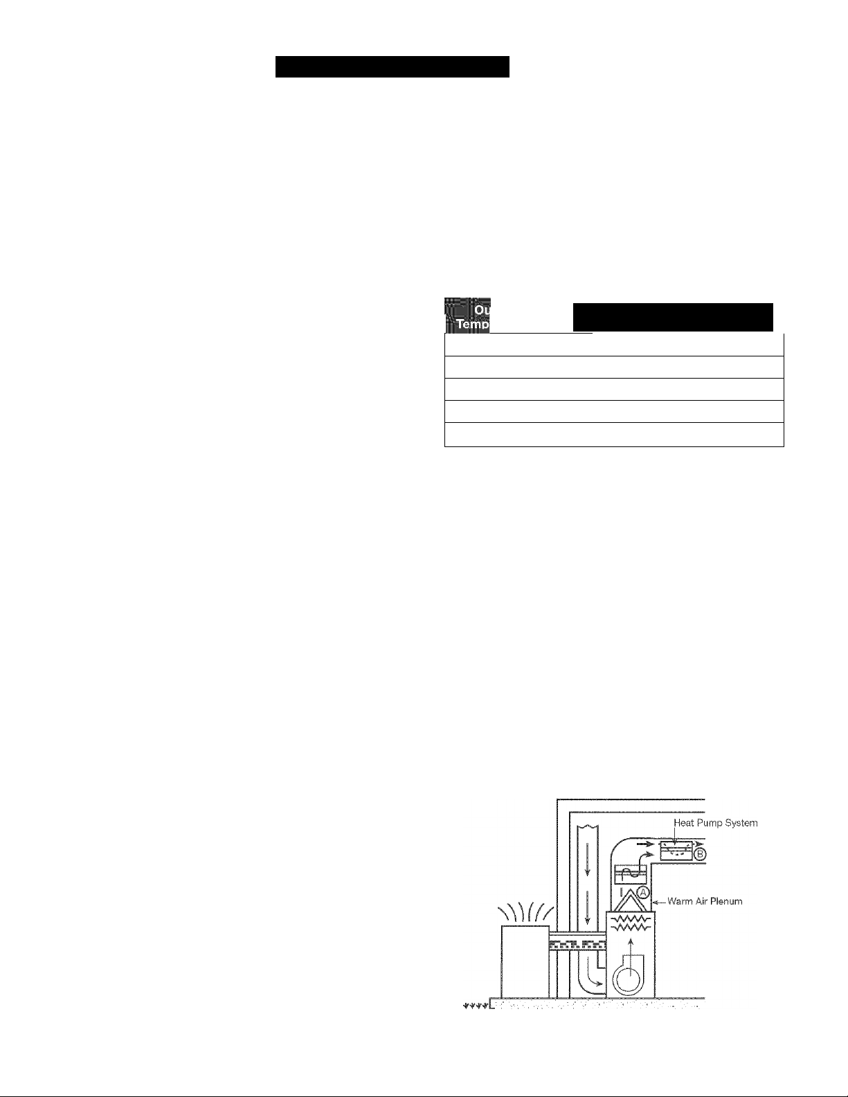
6. What is the safe humidity level for my home?
In order to determine the safe relative humidity for
homes exposed to various low outside tempera
tures, NESCA* conducted tests and published
recommended humidity levels for various outdoor
temperatures. These are shown in the chart below.
These levels help prevent damage to your home
such as water running down the walls or even
building up inside the walls.
The safe indoor relative humidity percentage is not
a fixed number but will increase or decrease as the
outdoor temperatures rise or fall.
Maximum Sate Recommended
Indoor Relative Humiditv
F
-10"
0° F 25%
F
10°
F
20°
30° F 35%
*NESCA = National Environmental Systems Contractors Association.
7. Can I install this Sears Humidifier with a heat
pump?
Yes, you can! This is a normal installation using
this Sears Furnace Mount Humidifier. No special
accessory is required. The diagram below shows
the functioning of the unit and also its placement
on the plenum. Installed with a heat pump, it will
evaporate 11 gallons, for a well insulated house up
to 2400 sq. ft.
To install with a heat pump, the humidifier should
be mounted on a warm air plenum (A) or duct (B)
of a heat pump system. Some of the warm air is
drawn from the duct, forced through the wetted
media and returned to the same duct. A self-con
tained blower moves the air from the duct through
the humidifier and back into the same duct. The
heat pump air delivery across the coil is not dis
turbed, or altered, in any way. The heat pump, there
fore, continues to operate at maximum efficiency.
20Y
30%
35%
Page 5
SELECTING A LOCATION
Carefully study the location that you choose for your
humidifier. Install the humidifier so that if the humidifier
or any connection should leak, the water will not cause
damage. Under no condition is Sears, Roebuck and
Co., and the manufacturer, to be held liable for any
water damage in connection with this humidifier.
NOTE: Never install humidifier in attic or crawl space
where freezing may occur or leaking will cause water
damage.
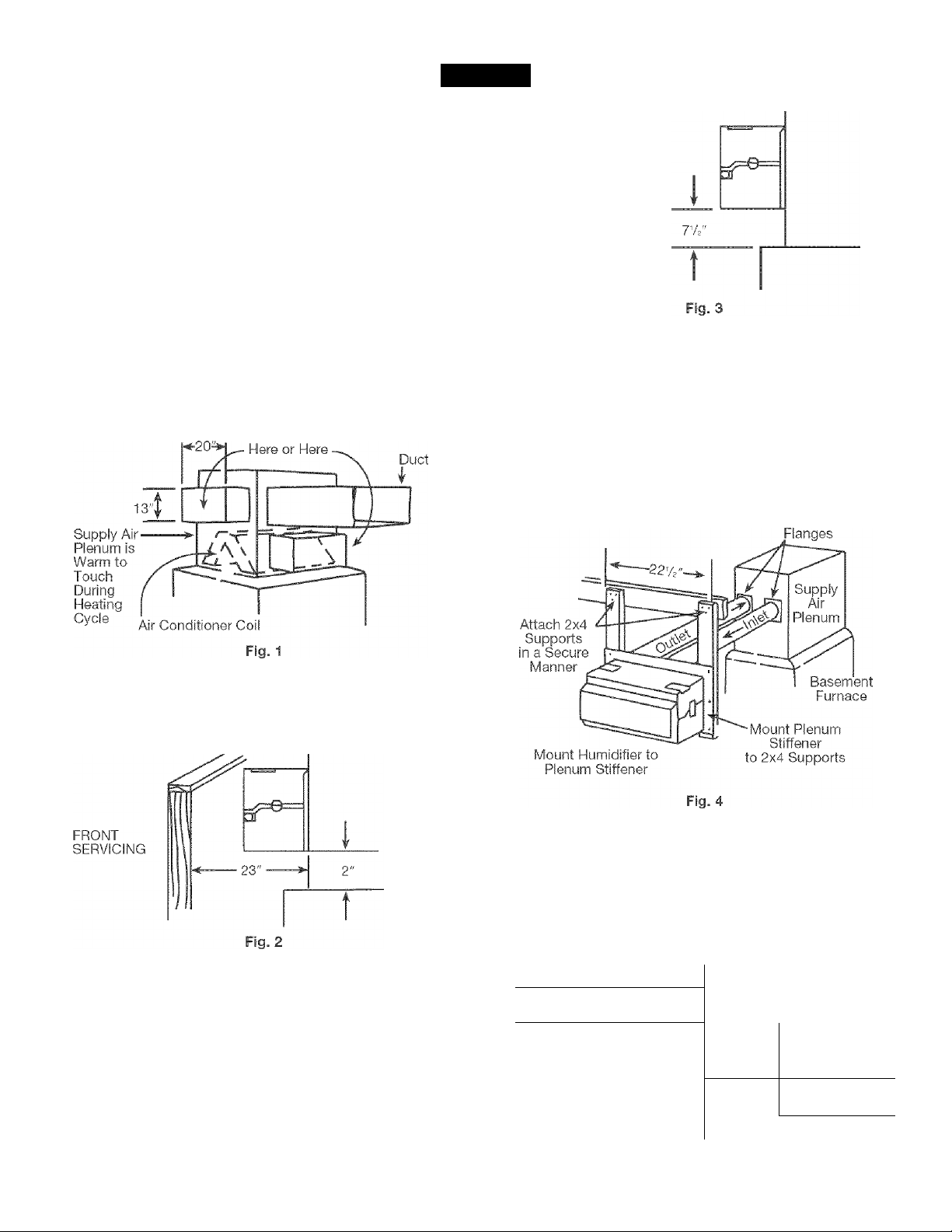
Measure the open area on the furnace supply air
plenum (Fig. 1). You will need a space 20" wide and
13" high. The humidifier will mount on a supply air
plenum isy?" wide by overhanging the sides. In
addition, you should have 12" of working area on each
side to make the electrical and water connections.
Place Humidifier
TALLAT
J
BOTTOM
SERVICING
TYPICAL REMOTE INSTALLATION
In some cases it is impossible to install the humidifier
directly to the supply air plenum (plenum too small,
horizontal attic furnace, etc.). For remote mounting,
see Fig. 4. Connect the humidifier to the supply air
plenum using the Remote Installation Kit - Sears
Stock No. 9372.
REMOTE INSTALLATIONS
Adaptor
NOTE: The easiest and quickest way to service the
humidifier will be from the front. To service from the
front you will need 23" of space in front of the plenum
and only 2" of space below the humidifier {Fig. 2).
If you do not have 23" of space in front, the humidifier
must be serviced from the bottom. Servicing from the
bottom will require
If you do not have the space needed, or have a
counterflow furnace, refer to the installations shown
in Fig. 4, 5 and 6.
NOTE: If you have an air conditioning coil in your
supply air plenum, install the humidifier above or to
the slope side of the coil.
CAUTION: Be careful not to damage coil when
cutting into plenum {Fig. 1).
l^/i clearance {Fig. 3).
HORIZONTAL FURNACE IN ATTIC OR
CRAWL SPACE
Always insure that the humidifier is located in the
living area (closet or utility room) to easily access
for maintenance/servicing and to prevent freezing
or water damage (Fig. 5).
Hot Air Plenum
1 Living Area
Attic ^ Furnace
Iniet/Outiet
f vjbl Humidifier
Ceiling k
Inlet/Outlet
Living Area
Floor A
t
Crawl U
Space Li
Ho
Fig. 5
Humidifier
_ Furnace ~~1
Air Plenum
Page 6
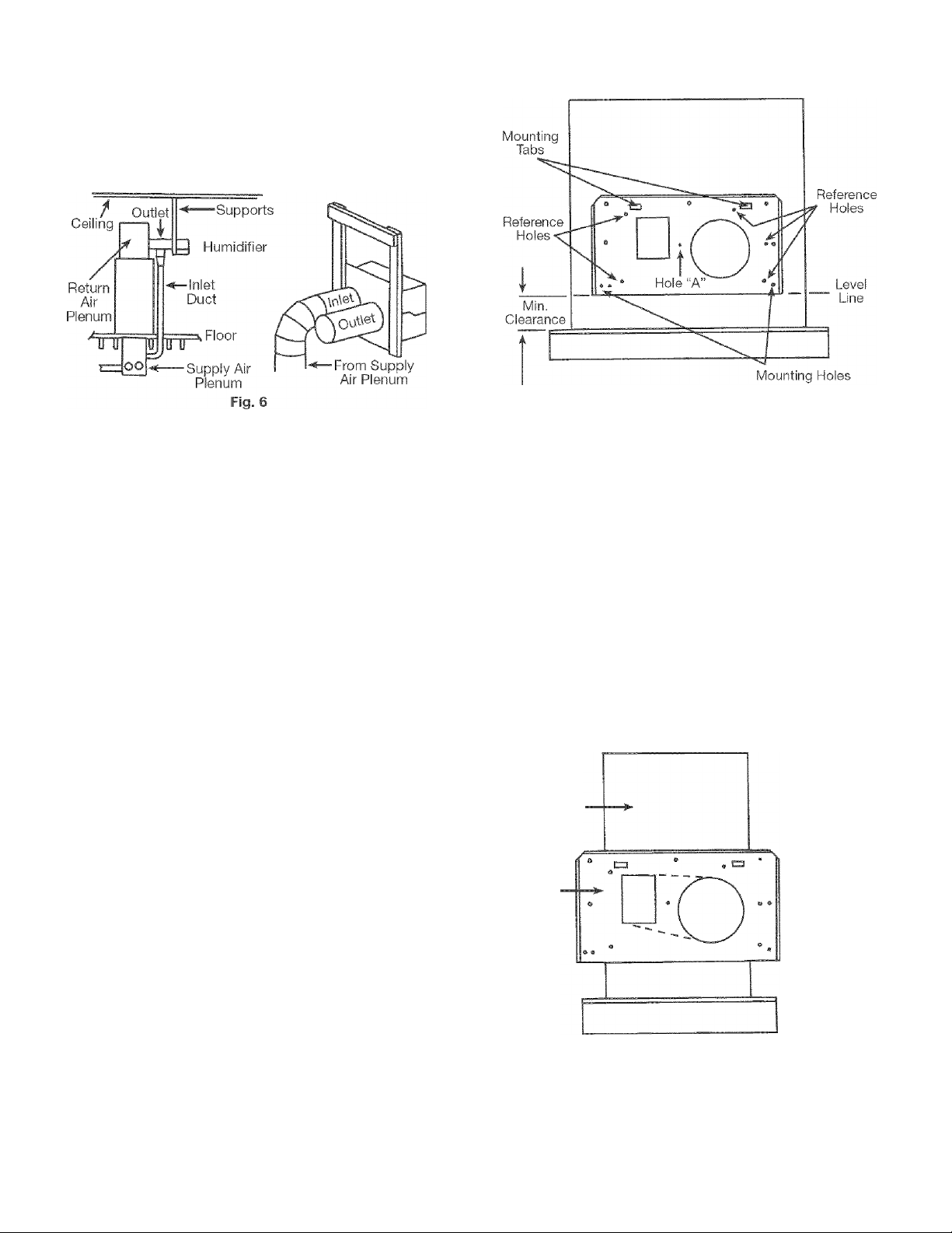
COUNTERFLOW FURNACE INSTALLATION
For installation of your humidifier on a counterflow
furnace, see Fig. 6. Connect the humidifier to the
supply air plenum using Remote Installation Kit,
Sears Stock No. 9372.
COUNTERFLOW FURNACE INSTALLATION
GRAVITY FURNACE INSTALLATION
SUPPLY AIR PLENUM
(Wider Than Stiffener)
2" to service from front (Fig. 2)
ZVA to service from bottom (Fig. 3)
Fig. 7
The humidifier works well on gravity furnaces because
of its self-contained blower system. Use the Remote
Installation Kit, Sears Stock No. 9372. The humidifier
must be at least 6" away from the plenum, due to the
higher operating temperature of the furnace.
NOTE: Furnace temperatures above 250°F may
cause failure of fiberglass parts.
Fiber Plenum Ducts
NOTE: The mounting screws supplied are for standard
installation on sheet metal plenum ducts.
If you have fiber plenum ducts, install the plenum
stiffener and components with thru-bolts, nuts, and
washers (not supplied), if necessary, reinforce the
humidifier mounting area on fiber ducts with sheet
metal and provide additional bracing as required to
support the weight of the humidifier and water. (This
fiber duct installation hardware is not supplied and
must be purchased from you local hardware store.)
You may also consider using the remote mount instal
lation if you have fiber ducts. Purchase the Remote
Installation Kit separately from Sears, Stock No. 9372.
1. The Plenum Stiffener is mounted on the supply
air plenum. Mark a level line at least 2" above the
top of the furnace on the selected surface, if
front service method (Fig. 2) is used. If the
humidifier is to be serviced from the bottom (Fig.
3), mark a level line at least iVb' above the top of
the furnace. Hold stiffener against the plenum
with the bottom edge on a level line and bent
edge flanges towards you. Using a pencil, mark
the location of all holes except hole “A” on
plenum (Fig. 7).
If plenum is narrower than stiffener:
The stiffener can be mounted on a plenum as narrow
as 13V2". The stiffener sides will extend past the
plenum (Fig 8). Begin installation as follows:
• New mounting holes will have to be drilled.
Drill the new holes only as far from the edge
as necessary. Use a 1/8" drill bit.
• Mark outline of rectangle as shown in Fig 8.
• Cut out this area of supply air plenum. If edges
are rough, file them smooth.
• Proceed to step 6.
SUPPLY AIR PLENUM
(Narrower Than Stiffener)
Plenum
Stiffener
Fig. 8
Page 7

If plenum is wider than stiffener:
2. The five reference hole marks you’ve made on
the plenum outline the area that must be cut out.
Mark straight lines connecting the five points.
WARNING: Wear safety glasses! Be sure not to drill
or cut into air conditioner coil or tubing! If electric drill
is used, be sure it is properly grounded.
3. Drill or punch a large hole In one corner of the
area to be cut out. This will allow you to insert tin
snips or a metal saw.
4. Cut along the lines connecting the five points. If
any of the cut edges are rough, file them smooth.
5. Drill the remaining holes marked on the plenum
with a 1/8" drill bit.
6. Mount the stiffener with the mounting tabs facing
out toward you. Use the seven sheet metal
screws, supplied, to fasten the stiffener. Make
sure the stiffener is flush with the plenum and is
airtight. Seal around the edge with caulking (not
furnished) if necessary.
7. Using the two finger grips (Fig. 9) on the lower
edge of the front panel, simply lift the front panel
about 1/8" straight up, swing the lower edge out,
pull down until the front panel is free. Remove
lower rod screw (Fig. 9).
Disconnect media motor wiring at the electrical
disconnect. Grasp both ends of the electrical
disconnect and simply pull apart (Fig. 9).
WARNING: Do not pull on wires to separate
electrical connector.
Upper Case Electrical Disconnect
Remove the reservoir assembly. Remove the
lower case from the humidifier by unfastening
the latches on both sides and removing the
lower rod screw. Set the lower case, reservoir
media wheel assembly, and front panel aside.
Remove the humidistat from the lower case.
8. Hang the upper case assembly on plenum stiff
ener mounting tabs (Fig. 7). Tabs may have to
be bent out slightly to fit into the slots in the
back of the upper case assembly. Secure the
upper case to the stiffener by pressing the
capped fastener (No. 47, Page 16) through the
back of the humidifier and into hole “A” (Fig. 10).
NOTE: It is very important that this fastener be
used. If the upper case is not attached with the
fastener, it could be dropped and damaged during
routine maintenance.
HUMIDISTAT
1, Locate the humidistat on the return (cold) air
plenum (Fig. 11). DO NOT install the humidistat
on the supply (hot) air plenum because the
humidistat cannot accurately measure indoor
relative humidity and will cause the humidifier to
function improperly.
Return
Air
Plenum
Gasket
Fig. 11
2. The humidistat mounts in a horizontal position.
Using gasket as a template, mark the location
of the two mounting holes and the opening for
the humidistat on the return air plenum.
3. Drill 1/8" holes for two mounting screws.
Cut out the opening for the humidistat.
Page 8

4. Peel off the paper from the back of the gasket
and stick the gasket on the return air plenum.
5. Remove the humidistat knob by gently pulling
straight out. Remove the cover screw and the
cover (Fig. 12).
Knob
Cover
Fig. 12
Mount the humidistat on the return air plenum
with the screws, furnished.
Y
Follow the wiring diagram for the standard or
alternate method of wiring you select. Use an
approved electrical cable containing copper
conductors only. Make all connections inside the
junction boxes and use approved strain relief or
conduit connectors to secure the cable to the
junction boxes per local code.
8.
For maximum safety, the humidifier must be
grounded. Use separate wire or ground to the
grounded 120V electric supply junction box by
using electrical cable with ground wire, and
connecting to the green wire in the humidistat
junction box and the humidifier junction box.
9. TEST - Replace the cover on the humidifier
conduit box. Replace the cover and knob on
the humidistat. Turn electrical power on at the
fuse box, turn the humidifier switch on (it is on
the left side of the upper case exterior) and turn
humidistat knob to “TEST” position to check for
humidifier blower operation. The furnace may
have to be running for the humidifier blower to
operate depending on electrical wiring method
used, if the humidifier blower does not start,
turn off electricity at the fuse box. Go over each
step in the wiring process. Retrace all the wiring.
Make sure everything is connected properly.
STANDARD WIRING METHOD
To connect the wiring it is necessary to remove the
cover of the conduit box located on the left side of
the upper case assembly (Fig. 13).
When the humidifier is wired using the standard wiring
method, it operates whether the furnace blower is
running or not, (you will hear the humidifier run), it
sounds much like your furnace because a blower is
used to provide maximum humidity from this humidifier.
This air movement sound is normal.
CAUTION: Connect the humidifier to 120V, 60 Hz
A.C. electric power only. Turn off the power at the
fuse box before making any line voltage connections.
Follow local electrical codes. Be sure proper grounding
procedure is followed. If in doubt, consult a competent
electrician.
DIRECT LINE WIRING METHOD FOR ANY
FURNACE
The easiest wiring method for the do-it-yourself
installer is direct line wiring. The humidifier will run
whenever the humidistat calls for humidity, whether
the furnace blower is running or not (Fig. 14).
GREEN OR aARFiGROUfJDi
_______
...............................................................
120 VAC
120
VAC-,
Junction Box
'Ground to copper or
galvanized water pipe.
Humidistat
ACKiHOTi—.. ..... BLACKmTl .
CJJflDi—¿a
ELECTRIC SUPPLY
Junction Box
CAUTION: Do not leave the humidistat set to the
“TEST” position.
After the humidifier blower operation has been
successfully tested, turn off electricity at the fuse
box and continue with water supply installation.
Fig. 14
Page 9

ALTERNATE WIRING METHODS
The alternate wiring methods are for your humidifier
to operate only when the furnace blower is on and
the humidistat is calling for humidity. The method you
select will depend on your furnace control system.
Find the type of system you have and follow that
method. Also, if the method selected requires a sail
switch or relay, this item must be purchased separately.
Alternate Method - 1
For ANY Forced Air Furnace
Humidifier runs only when furnace blower is running
and the humidistat calls for additional humidity. The
humidifier must be turned off manually during cooling
season (Fig.15).
Sail
120
Volt
Humidistat
Fig. 15
Install Sail Switch In Return Air Plenum (use normally
open contacts). Purchase this accessory separately
if needed. Available from Sears Product Services:
Phone: 1-800-366-7278 Specify Division 42 PLS 042
Part No. 9114
Alternate Method - 3
Any furnace/air conditioning system with
multi-speed furnace blower
Humidifier runs only when furnace blower is running
and the humidistat calls for additional humidity.
Humidifier is automatically “off” during cooling season.
With the thermostat in the “FAN ON” position, the
humidifier will not operate (Fig. 17).
Black T- ,
Tape
Red
Wire
—► To Low
To “G” on
Transformer
Relay Panel
SPOT Relay
{Sears Stock
No. 42-9248)
Heating
Speed
Motor Lead
o
TO
HUMIDIFIER
<3
White
To “C” on
Transformer
Relay Panel
Humidistat
NEUTRAL 120 VOLT
Fig. 17
Alternate Method - 4
Sears “15” and “20” furnace with electrical
comfort center
Humidifier runs only when the furnace blower is run
ning and the humidistat call for additional humidity.
The humidifier must be turned off manually during
the cooling season (Fig. 18).
Alternate Method - 2
Any furnace with single speed, 120 ¥AC Blower
Humidifier runs only when furnace blower is running
and the humidistat calls for additional humidity, it’s not
necessary to turn humidifier OFF during the summer
(Fig. 16).
White
FAN MOTOR
Fig. 16
NEUTRAL
(White)
Fig. 18
NOTE: The humidifier and humidistat have a green
ground wire which must be connected to ground
(refer to Page 8, Step 8 of Humidistat).
Page 10

WATER SUPPLY
1. Water for the humidifier must be taken from a
nearby cold water line. Turn off the water supply.
Drain by opening a faucet at a lower level of the
line.
2. Position the saddle valve on the water line as
close to the humidifier as possible. You have
been supplied with 10 feet of 1/4" plastic tubing.
NOTE: When measuring the distance from the
saddle valve location to the humidifier, keep in
mind that the tubing must be supported; there
fore, it must run along the ceiling and walls.
Measure along the path that the tubing will follow.
3. Back out the piercing pin by turning the “T” handle
counter clockwise and clamping the saddle valve
body securely on the water line with a rubber
gasket positioned as shown in Fig. 19. On galva
nized or copper pipe over 5/8", first drill a 5/32"
diameter hole in the pipe.
WARNING: For safety, use a hand drill or grounded
electric drill.
4. Turn the handle clockwise until it has pierced the
water line and valve is completely closed {Fig. 19).
8. Close previously opened faucet. Turn on the main
water supply. Place a pail under the end of the
tubing. Open the saddle valve. Flush the line.
Make sure there are no leaks along the line or at
the valve. Turn valve off.
9. Reassembly of humidifier case.
a.
For Front Servicing:
Attach the lower case making sure both side
latches are secure. Slide the reservoir assembly
(Fig. 20) into case, connect the electrical
disconnect for the media motor. Install lower
rod screw (Fig. 9).
For Bottom Servicing:
b.
Place the reservoir assembly (Fig. 20) into the
lower case and attach the lower case, making
sure both side latches are secure. Connect the
media motor electrical disconnect. Install
lower rod screw (Fig. 9)
Media Motor
Fig. 19
Partially uncoil the tubing. Slide the brass com
pression nut over the tubing. The threads in the
nut must face the tubing end. Place the brass
compression sleeve as shown in (Fig. 19). Slip
brass insert into end of the tubing.
Insert the tubing end into the saddle valve at
threaded stem “A” (Fig. 19) as far as it will go.
Thread the brass compression nut onto the
valve, then tighten gently with a wrench. Take
care not to over-tighten the nut.
7.
Unwind the rest of the tubing. Take care not to
kink it. Run the tubing along flat surfaces to the
humidifier. Support the tubing as needed to
avoid contact with furnace.
Fig. 20
NOTE: Make sure top edge of media motor panel
and reservoir divider are firmly seated with panel clip
installed (Fig. 21 & 22).
10
Page 11

10. Remove the quick disconnect socket, brass
compression nut, and brass sleeve from hardware
bag (Fig. 23). With water supply tubing cut to the
proper length, slide the brass compression nut
and sleeve over the tubing as described in Step
5, Page 10. Slip the brass insert, into the end of
the tubing.
11. Insert the tubing end into the quick disconnect
socket as far as it will go and hold it there. Thread
the brass compression nut onto the quick dis
connect socket, then tighten using two wrenches,
one to hold quick disconnect socket and one to
tighten nut. Do not over-tighten nut (Fig. 23).
12. Connect the quick disconnect socket to the
plug on the valve body (Fig. 24).
Sleeve
To connect, pull back sleeve, push socket onto
plug, release sleeve.
To disconnect, pull back sleeve, unlocking quick
disconnect and sealing water supply line, separate
from the plug.
13. It is best to install an overflow line. Local
building codes may require it. The overflow hole
is in the bottom left front corner of the reservoir
(Fig. 20). Use 1/2" inner diameter rubber or plas
tic tubing to connect to drain. (Tubing not sup
plied. Purchase at your local hardware store.)
Fig. 23
11
Page 12

I
OPERAT
J
WATER LEVEL CHECK
1,
Turn on the water supply at the saddle valve.
Water should now flow into reservoir. If not,
check that saddle valve is open. Check for leaks
at all connections.
2.
Allow Reservoir to fill and check that water level
is correct. The water level should be between the
two marks on the front side of the reservoir divider
(Fig 25). If the water level is not between the two
marks a float adjustment may be required. Refer
to the Adjusting Float instructions found in the
Maintenance Section on Page 13 to adjust float.
HUMIDISTAT
1, Set the knob to the lowest outdoor temperature
expected for a 24-hour period. Because of differ
ences in house construction, you may want to try
a higher or lower setting to achieve proper
humidity (Fig 26).
mmsm
»BIT»«
emram,
u'<(i
FOB, MI'Xf
LLAVi U,M '..I nr. •
K-w
SPP
Fig. 26
Change the knob settings as outdoor
temperature changes occur.
WARNING: Do not leave the knob in the in the
“TEST” position above “+20” or the humidifier will run
constantly.
Test - Turn on the electricity at the fuse box, turn
the humidifier power switch to the “ON” position
and turn humidistat knob to the “TEST” position.
The humidifier blower should operate and the
media wheel should rotate slowly at approximately
one (1) revolution per minute. The furnace may
have to be running for the humidifier to operate,
depending on the wiring method used.
4.
install front panel by sliding top of panel into
channel in upper case. Swing panel bottom in
and down to engage channel in lower case.
If sweating of windows or walls occurs:
1. Check the indicator setting. The indicator should
point to the number that represents the lowest
expected 24-hour outdoor temperature. Wait 24
hours before changing the indicator setting.
2. If the indicator setting in Step 1 is correct, and
conditions have not changed, rotate the knob
back and forth from the “TEST” to minimum
humidity setting. If the humidifier goes on and
off, the control is operating properly.
3. Remember, to increase the indoor relative
humidity, turn the indicator clockwise ^ .
To decrease indoor relative humidity, turn
counter-clockwise ^ .
NOTE: Because of differences in home construction,
the number of occupants, and living habits in some
homes, when the anticipated 24-hour lowest outdoor
temperature is,for example, +10°F, your ideal humidi
stat setting may be the low position.
12
Page 13

AINTENANC
I
Your humidifier will maintain its efficiency for a long
period of time. If it is not serviced, damage may
result. Service it every mointh. Follow instructions
below. Since water conditions vary, it may be nec
essary to service either more or less often.
Establish your own servicing schedule.
REGULAR MAINTENANCE
1. Turn off electricity at the fuse box.
2. Disconnect the water supply tubing at the quick
disconnect. The water will automatically shut off.
3. Remove the drain line {if used) and catch any
water with a pail.
4. Front Service (preferred):
Remove the front panel, disengage the media
motor electrical disconnect, remove the overflow
tubing, slide out the reservoir and media wheel
assembly.
5. Bottom Service (only if insufficient space in
front):
Remove the front panel, disengage the media
motor electrical disconnect, remove the overflow
tubing, remove the lower rod screw, unlatch and
remove the lower case and slide out the reservoir
and media wheel assembly.
Use care when removing either the reservoir
assembly or the lower case and reservoir assem
bly since the reservoir is filled with water.
6. Remove the media motor and panel assembly by
releasing the clip and sliding the assembly
upward from the reservoir divider. Slide the
reservoir divider upward from the reservoir and
remove.
7. Empty the water from the reservoir.
8. Rinse and clean the reservoir, media, media
wheel, and reservoir divider after removing any
lime buildup. Detergent such as vinegar or Sears
All-Purpose Humidifier Cleaner (Stock No. 42
14713) may be used to loosen lime deposits.
NOTE: To aid in future cleaning, an optional
accessory Reservoir Liner may be purchased
through the Sears Parts Department; call 1-8004-MY-HOME to order Part No. 215682-01 (see
Exploded View, Page 17). The liner may be flexed
to aid in loosening accumulated lime buildup.
CAUTION: Do not put parts in a dishwashing
machine. The high temperature in the washer may
damage parts. Handle all parts carefully. Be careful
that no water or cleaner enters the motor or electrical
parts.
J
9. Deposits will form on the media pad. Unless the
deposits are light and the pad can be cleaned, it
must be replaced. Replacement pads are avail
able from Sears (Stock No. 42-9336).
10. If the reservoir has been overflowing, the float
valve button may be worn. In normal operation,
this button will eventually erode much like a
faucet washer. Remove the float valve button,
turn it over, and reinsert. Replacement buttons
are available by calling the Sears Parts
Department; call 1-800-4-MY-HOME.
11. Reassemble the media pad in the media wheel.
Replace the reservoir, divider, media wheel, media
motor, and panel assembly. Engage panel clip.
12. Reassemble humidifier in the following manner:
A. Front Service:
Slide the reservoir and media wheel assembly
into the humidifier, engage the media motor
electrical disconnect, attach the overflow
tubing, connect the water supply tubing.
B. Bottom Service:
Slide the reservoir assembly into the lower
case, attach the lower case assembly to the
humidifier (make certain side latches are
secured), engage the media motor electrical
disconnect, attach the overflow tubing and
water supply tubing. Reinstall lower rod screw.
13. Connect the water supply tubing at the quick
disconnect and allow the reservoir to fill. Check
the water level, adjust the float if required, and
reinstall the front cover.
14. Turn on the electricity at the fuse box, push the
humidifier switch to “ON” and turn the humidistat to the “TEST” position to check the humidifier
operation. The furnace may have to be running
for the humidifier to operate, depending on elec
trical connection. Set the humidistat according
to the outdoor temperature as instructed on
label.
CAUTION: Do not leave in “TEST” position.
maintenance sticker
It is suggested that you apply the Kenmore 303.93806
Furnace Humidifier Maintenance instructions sticker
to either the return air plenum or a place in which
they will be easily seen. These instructions provide a
quick reference for typical maintenance that may be
needed on this product.
13
Page 14

ADJUSTING THE FLOAT
1. Disconnect the water supply at quick disconnect.
2. Remove the float and float arm by pulling out the
float pivot pin (Fig. 27).
*Floa.t Valve
Button
Valve
Body
Float
"Reverse button if it has not been used.
Replace vtfith new button if both sides are worn.
Fig. 27
3. Raise the water level by rotating the float clock
wise. Rotate the float counter-clockwise to lower
the water level, (one complete turn will change
the water level 1/8".)
4. Turn the humidifier power switch OFF.
5. Disconnect the media motor electrical disconnect.
6. Remove the reservoir and detach the clip.
7. Remove the media motor panel and media
wheel.
8. Remove the reservoir divider. Pour the water
from the reservoir into a suitable container.
9. Reassemble the humidifier. Reconnect the water
supply and recheck the water level.
SERVICING THE FLOAT
If the humidifier has been overflowing, the float valve
button may be worn. This button will wear much like
a faucet washer.
To service:
1. Turn off the water at the saddle valve.
2. Disconnect the water line at the humidifier.
3. Remove the float from the humidifier (pull out
pivot pin).
4. Remove the float valve button and turn it over or,
replace it if both surfaces are worn, as shown in
Fig. 27.
5. Reinstall and turn on the water and test the float.
CAUTION: Do not use tablets in an attempt to control
lime deposits in this humidifier! Use of tablets may cause
the humidifier to splash causing damage to the humidifier
or furnace.
IF AIR IS TOO DRY (AND WINDOWS ARE NOT
SWEATING):
1. Wait until the furnace blower comes on. Then
rotate humidistat knob back and forth from TEST
to the OFF humidity setting, if the humidifier
goes on and off, the humidistat is operating
properly. Check for proper operation of the
humidifier.
2. If the humidifier is off when furnace blower is on,
readjust the humidistat by turning the knob so
the indicator points to the setting for the lowest
24-hour temperature predicted.
IF SWEATING OF WINDOWS OR WALLS
OCCURS:
1. Press the switch on the humidifier to the OFF
position. When moisture is no longer present, set
the humidistat indicator to the setting for the
lowest anticipated 24-hour outdoor temperature.
Switch the humidifier to the ON position.
2. If sweating reoccurs, repeat Step 1, allowing for
an additional 10“F lower setting of the outdoor
temperature than anticipated in the next 24
hours. Continue this procedure until the humidity
level is stabilized.
NOTE: Because of differences in home construction,
the number of occupants, and living habits in some
homes, when the anticipated 24-hour lowest outdoor
temperature is, for example, +10°F your ideal humidi
stat setting may be the low position.
SUMMER SHUTDOWN
Refer to the following when shutting down your
humidifier for the summer:
• Turn the humidistat dial counter-clockwise to the
minimum setting position.
• Push the switch to “OFF” and close the saddle
valve.
• Clean as instructed above but leave the reservoir
empty.
• As a reminder, you might want to put a tag or
sticker on the unit indicating it has been shut
down for the summer and will require start-up in
the fall
FALL START UP
• Push the switch to “ON,” and open the saddle
valve.
• Set the humidistat in the “TEST” position.
• Check for proper water level and media wheel
operation.
• Set the humidistat according to the outdoor tem
perature as instructed on Operation Instruction
label. The unit is back in operation.
CAUTION: Do not leave in “TEST” position.
14
Page 15

TROUBLESHOOTING
Frequently, what seems to be a major problem can be
solved very easily. Listed below are the common con
cerns with any humidifier.
Check the simple things first. Remove the front panel
and see if there is a crusty, white lime buildup on the
media pad. The lime buildup won’t hurt the humidifi
er, but will reduce its output. Low output might just
mean your humidifier needs cleaning. While you’re
checking for lime buildup, look to see if the media
wheel is turning. If not, check the power supply.
PROBLEM CHECK CORRECTION
Too Little
Humidity
1. if humidifier needs cleaning 1. Clean humidifier and clean or replace media
pad
2. If media wheel is rotating 2. a. Clean or replace media pad
b. Inspect main fuse or circuit breaker
c. Check to see if media motor gear is rotating
and engaged with media wheel gear
d. Check if humidistat setting is too low; turn
knob clockwise to increase humidity
3. Humidistat setting 3. Set for proper outdoor temperature - lowest
expected temperature for a 24-hour period
4. If not enough water is going to unit 4. Turn on saddle valve and check for possible
obstruction in water line. Is water supply
connected?
5. If there is excessive air loss in house 5. Close fireplace damper, seal around doors
and windows
6. If water level is correct 6. Adjust float
Too Much
Humidity
1. Humidistat setting 1. Turn knob counter-clockwise to decrease
humidity
2. For other humidification sources 2. May be a temporary condition caused by
moisture from laundering, bathing, cooking, etc.
Humidifier 1. Is the humidifier level? 1. Level unit
Overflows
2. Is the float valve button worn? 2. Remove the float valve button and turn it over
or, replace if both surfaces are worn, as shown
in Fig. 27
Humidifier
Making Noise
Humidifier
Motor Comes
On When
Furnace Isn’t
Running
1. Mounting or plenum
2. Water pressure
1. Tighten all fasteners
2. A slight sound is normal as water enters
humidifier
3. Media Wheel 3. Check clearance of media wheel in reservoir
4. Blower Motor 4. Loosen mounting nuts on rubber grommets so
they are just flush with mounting studs
This is a normal condition
1. If heating season is over
1. Turn knob on humidistat to minimum setting
2. If heating season is just starting 2. This is a normal condition since humidistat is
controlling humidifier
15
Page 16

REPAIR PARTS
KENMORE “3000” CENTRAL HUMIDIFIER
MODEL NO. 303.9380612
KEY
NO.
1 21567101 Plenum Stiffener
2 STD 610803 Screw (11 Req.) 26 21569101 Float Valve Body
3 21568601 Upper Case
4
5 28126101 Switch
6 21568301 Switch Plate 31 21568101 Reservoir
7 21572501 Conduit Box
8 STD 541010 Nut (2 Req.) (No. 10-24)
9 030060-04 Screw (Ground)
10 28112004 Strain Relief 36 21567702 Reservoir Divider
11 STD 511003 Screw (No. 10-24 x 3/8"
12 22515601 Conduit Box Cover
13 STD 610803 Screw (2 Req.) (No. 8B x 3/8"
14 21570101 Front Panel
15 35561801 Saddle Valve
16 21582703 Plastic Supply Tubing (1/4" x 10 ft.)
17 STD 541006 Nut (2 Req.) (No. 6-32) 45 35586201 Blower Motor
18 21568401 Media Motor Panel
19 35585901 Media Motor
20 STD 510603 Screw (2 Req.) (No. 6-32 x 3/8"
21 21572701 Plug, Quick Disconnect
22 21586101 Socket, Quick Disconnect
23 STD 575025 Brass Compression Nut
24 35561102 Float Valve
PART
NO. DESCRIPTION
(No. 8A X 3/8" Slotted)
21595401 Rod
(No. 10-24 X 1/4" Hex &
Slotted Head) 35 21590701 Panel Clip
Cross Recess)
Cross Recess) 40 35587001 Blower Wheel
(Includes Key Nos. 23 & 32)
(Includes Key Nos. 17 & 20)
Cross Recess) 49 28154601 Wire Harness
(Includes Key Nos. 25 - 30) 21595801 Owner’s Manual
KEY
NO.
25 03029401 Locknut
27 28110201 Pivot Pin
28 22513801 Float Arm
29 28110101 Float Valve Button (1 Req.)
30 42063901 Float
32 STD 575026 Brass Compression Sleeve 1/4"
33 35586301 Lower Case
34 21591001 Reservoir Divider Assy.
37 35586101 Media Wheel & Gear
38 35569203 Media Pad (42-9336)
39 21575001 Clip (3 Req.)
41 03013712 (Nut (4 Req.) (No. 8-32)
42 28084602 Grommet (4 Req.)
43 28108701 Eyelet
44 21569801 Fan Blade
46 STD 375005 Wire Nut (2 Req.)
47 03021303 Capped Fastener
48 21551001 Wire Clip
50 41067501 Brass Insert (2 Req.)
51 03028603 Screw (2 Req.)
52 21568201 Optional Accessory Reservoir
A
PART
NO. DESCRIPTION
(Includes Key Nos. 35 & 36)
(Includes Key No. 39)
(Includes Key No. 44)
Liner
21593601 Humidistat
THIS IS A PARTS LIST, NOT A PACKING LIST. *Not Shown
16
Page 17

REPAIR PARTS
KENMORE “3000” CENTRAL HUMIDIFIER
MODEL NO. 303.9380612
EXPLODED VIEW
17
Page 18

Get it fixed, at your home or ours!
Your Home
For repair-in your home-of all major brand appliances,
lawn and garden equipment, or heating and cooling systems,
no matter who made it, no matter who sold it!
For the replacement parts, accessories and
owner’s manuals that you need to do-it-yourself.
For Sears professional installation of home appliances
and items like garage door openers and water heaters.
1-800-4-MY-HOME® (1-800-469-4663)
Call anytime, day or night (U.S.A. and Canada)
www.sears.com www.sears.ca
Our Home
For repair of carry-in items like vacuums, lawn equipment,
and electronics, call or go on-line for the location of your nearest
Sears Parts & Repair Center.
1 -800-488-1222
Call anytime, day or night (U.S.A. only)
www.sears.com
To purchase a protection agreement (U.S.A.)
or maintenance agreement (Canada) on a product serviced by Sears:
1-800-827-6655 (U.S.A.) 1-800-361-6665 (Canada)
Para pedir servicio de reparación
a domicilio, y para ordenar piezas:
1-888-SU-HOGAR®“
(1-888-784-6427)
Au Canada pour service en français:
1-800-LE-FOYER^^
(1-800-533-6937)
www.sears.ca
® Registered Trademark /™ Trademark / Service Mark of Sears, Roebuck and Co.
® Marca Registrada / Marca de Fábrica / Marca de Servicio de Sears, Roebuck and Co.
Marque de commerce / ““ Marque déposée de Sears, Roebuck and Co.
) Sears, Roebuck and Co.
 Loading...