

Kenmore 27298401490, 27298400490 Owner’s Manual
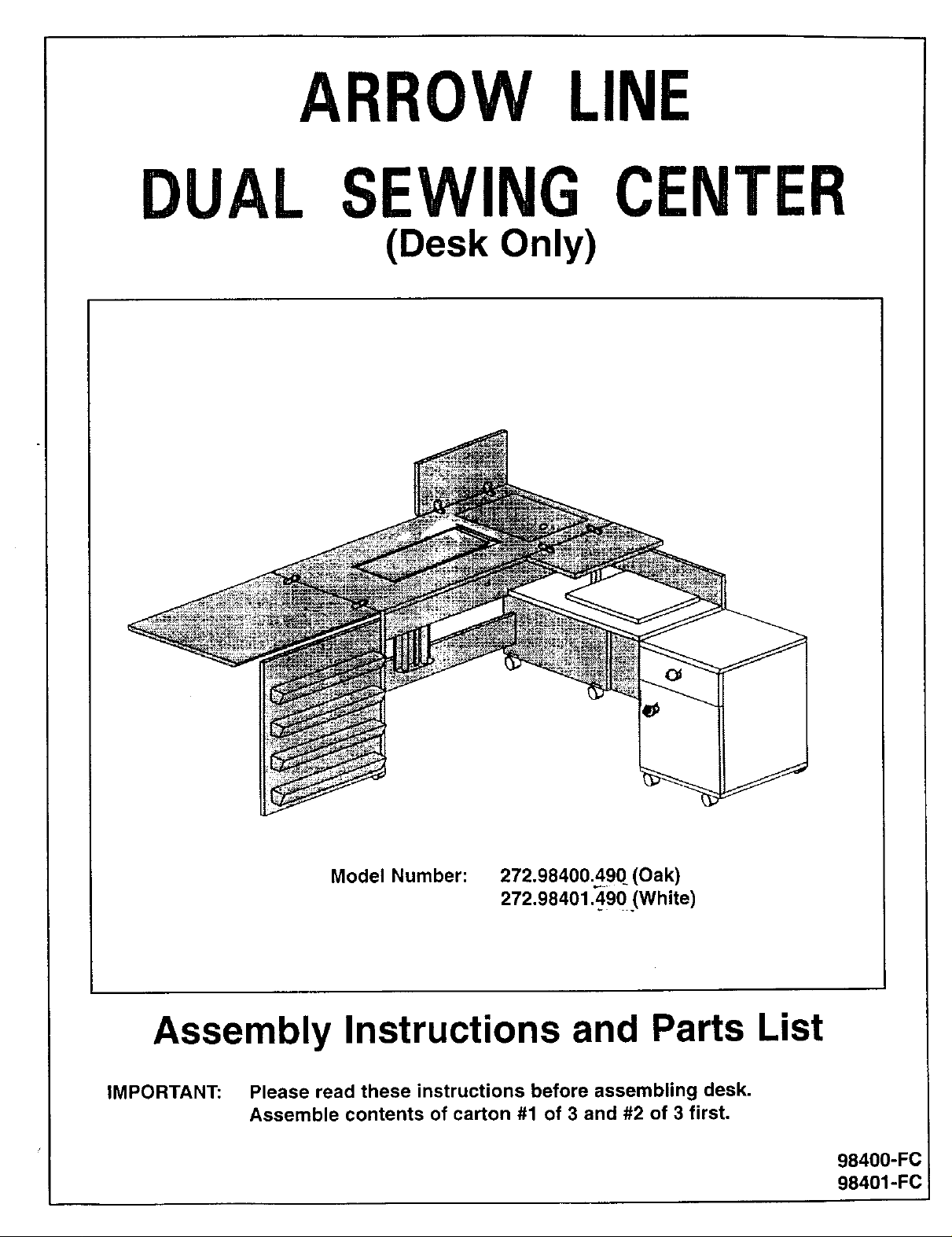
ARROW LINE
DUAL SEWING CENTER
(Desk Only)
Model Number:
272.98400A90 (Oak)
272,98401.490 (White)
Assembly Instructions and Parts List
IMPORTANT: Please read these instructions before assembling desk.
Assemble contents of carton #1 of 3 and #2 of 3 first.
98400-FC
98401-FC
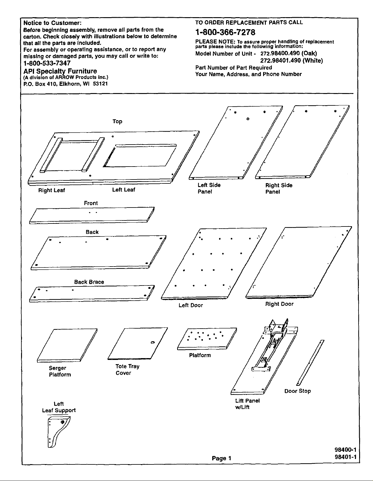
Notice to Customer:
Before beginning assembly, remove all parts from the
carton. Check closely with illustrations below to determine
that all the parts are included.
For assembly or operating assistance, or to report any
missing or damaged parts, you may call or write to:
1-800-533-7347
API Specialty Furniture
(A division ofARROW Products Inc.)
P.O. Box 410, Elkhorn, Wl 53121
Top
TO ORDER REPLACEMENT PARTS CALL
1-800-366-7278
PLEASE NOTE: To assure proper handling of replacement
parts please include the following information;
Model Number of Unit - 272.98400.490 (Oak)
272.98401.490 (White)
Part Number of Part Required
Your Name, Address, and Phone Number
• /
./
Right Leaf Left Leaf
Front
/ /
Back
./ ./
Back Brace
/. ,.-7
/./
Left Side
Panel
Left Door
Right Side
Panel
Right Door
8erger
Platform
Left
Leaf Support
Tote Tray
Cover
Platform /_
Page 1
Door Stop
Lift Panel
w/Lift
98400-1
98401-1
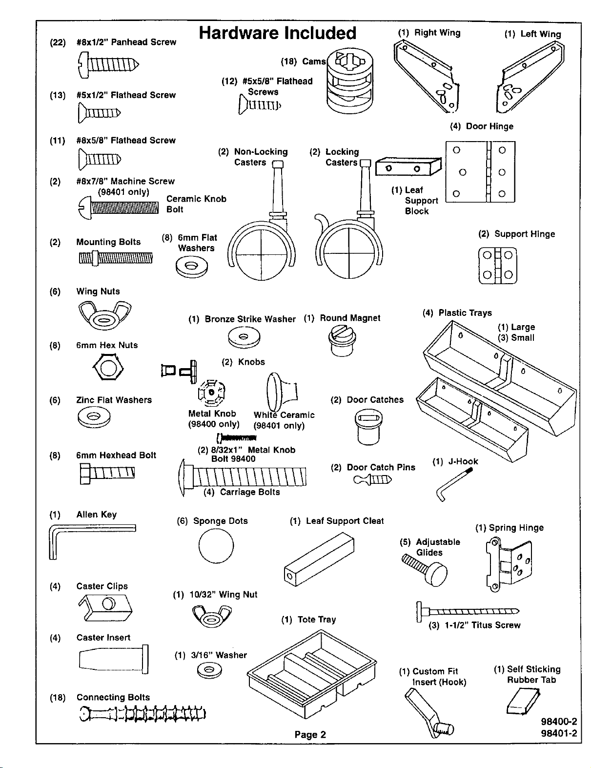
#8xl/2" Panhead Screw
(22)
#5x1/2" Flathead Screw
(13)
(11) #8x5/8" Flathead Screw
(2) #8x7/8" Machine Screw
(98401only)
Ceramic Knob//\\\///\\//\\/\\/\//\\\\/\\/\\\//\\//'_Bolt
Hardware Included
(18) Cams_
(12) #5x5/8" Flathead t',_l
8orawe _1
(2) Non-Locking
Casters
(2) Lockin!
Casters
]
(1) Right Wing
(4) Door Hinge
(1) Left Wing
r. 1° I °1
I° o_ o Ho
(1) Leaf I o H o I
Support I tl I
Block
(2)
Mounting Bolts
Washers
(8) 6mm Flat _ 1
Q
(6)
Wing Nuts
(1) Bronze Strike Washer (1) Round Magnet
Q @
(8)
%¢>
6mm Hex Nuts
©
(6)
Zinc Flat Washers •_ (2) Door Catches
6mm Hexhead Bolt
(8)
Allen Key
(1)
_] I_ L_--_o; 2) Kn°bs ite_C_ra
Metal Knob Wh mic
(98400 only) (98401 only)
[p,,,,,.,..
(2) 8/32x1" Metal Knob
Bolt 98400
(6) Sponge Dots (1) Leaf Support Cleat
(2) Door Catch Pins
(2) Support Hinge
(4) Plastic Trays
(1) Large
(3) Small
(1) J-Hook
(1) Spring Hinge
(5) Adjustable
(4)
Caster Clips
(1) 10132" Wing Nut
(4) Caster Insert JJl_,.
_'- _ (1) 3/16" Washer
Q
(18) Connecting Bolts
(1) Tote Tray
Page 2
%
(3) 1-1/2" Titus Screw
(1) Custom Fit
Insert (Hook)
(1) Self Sticking
Rubber Tab
98400-2
98401-2
UnderstandingHowthe "ARROW-LOC" Cam FastenerWorks.
TOWARDS
ARROW
HOLEIN
EDGE
1. Position bolt in 2. Press cam into 3. Insert bolt through
pre-drilled hole and pre-drilled hole until pre-drilled hole in
turn until tight, flush with surface, edge of panel.
4. To lock, rotate cam
until tight, using
allen key provided.
Cabinet Assembly
Step 1. Place Top, Left and Right Sides on a flat protected surface (to prevent scratching of parts),
thread Connecting Bolts (18 total) into pre-drilled holes (as shown in FIG. 1). Install Cams
(18 total) by pushing a Cam into each hole flush with surface, The arrow on the Cams should
be turned (using a regular screwdriver or Allen Key provided) to face the hole in each edge
where the Connecting Bolts will enter.
Step 1A. We are providing (1) White Plastic Hook, to be used to store your Custom Fit Sewing Head
Insert. Install in hole on Left Side Panel (as shown in FIG. 1).
I NOTE:
• = Connecting Bolt
= Cam
Top Assembly
FIG. 1
/iJJ
Right Leaf Left Leaf
Back
./ " .7
Back Brace
/- #
Left Side Panel Right Side Panel
Turn over front, tap in (2) Door Catches (be sure to have
the slots go from left to right, as shown in FIG. 1A)
Front ( Back Side)
/. . .y
Tap in Catches here FIG. 1A
/ 1I /
Front (Front Side)
98400-3
Page 3 98401-3
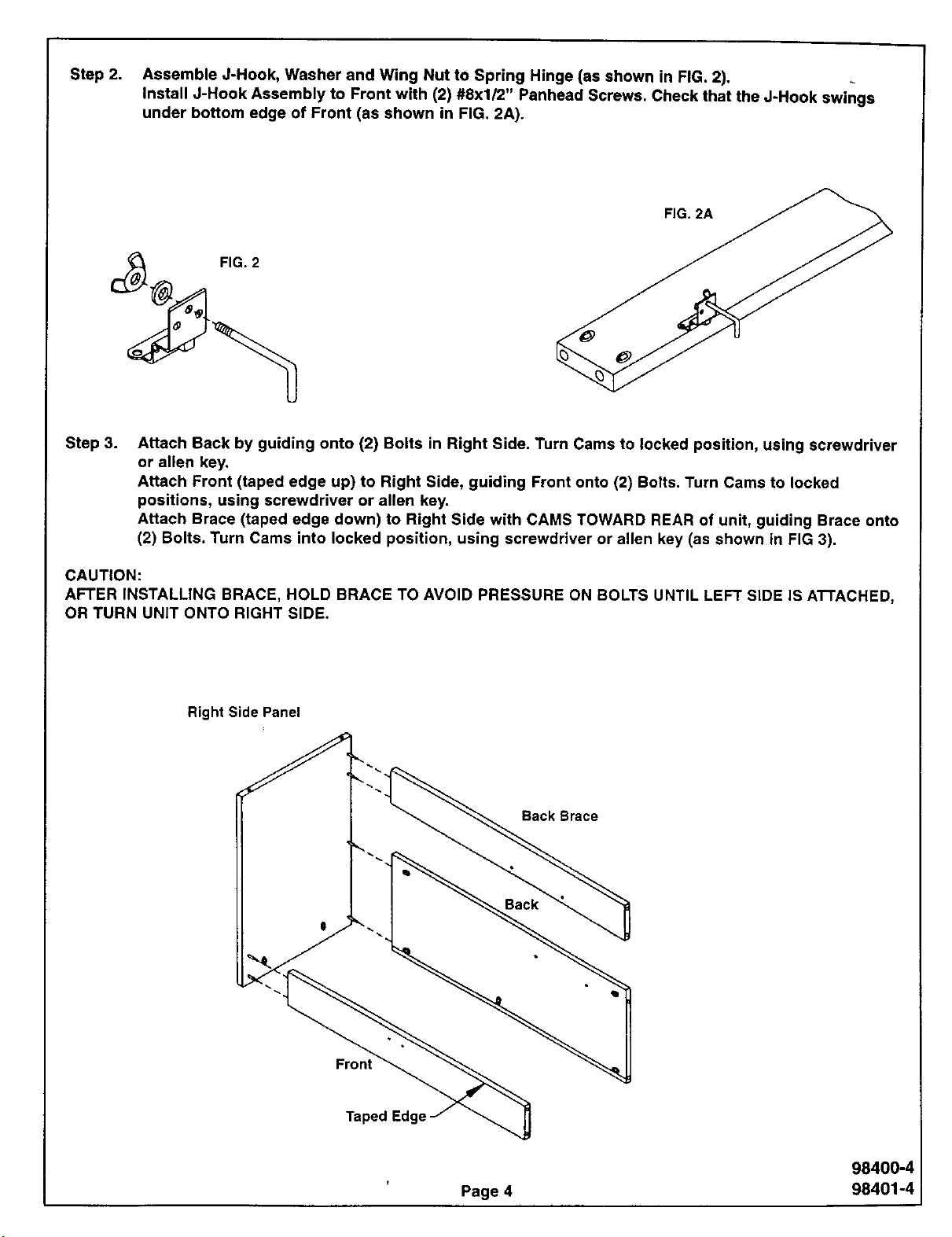
Step 2; Assemble J-Hook, Washer and Wing Nut to Spring Hinge (as shown in FIG. 2).
Install J-Hook Assembly to Front with (2) #8xl/2" Panhead Screws. Check that the J-Hook swings
under bottom edge of Front (as shown in FIG. 2A).
FIG. 2A
Step 3.
Attach Back by guiding onto (2) Bolts in Right Side. Turn Cams to locked position, using screwdriver
or allen key.
Attach Front (taped edge up) to Right Side, guiding Front onto (2) Bolts. Turn Cams to locked
positions, using screwdriver or allen key.
Attach Brace (taped edge down) to Right Side with CAMS TOWARD REAR of unit, guiding Brace onto
(2) Bolts. Turn Cams into locked position, using screwdriver or allen key (as shown in FIG 3).
CAUTION:
AFTER INSTALLING BRACE, HOLD BRACE TO AVOID PRESSURE ON BOLTS UNTIL LEFT SIDE iS ATTACHED,
OR TURN UNIT ONTO RIGHT SIDE.
Right Side Panel
Back Brace
I
Front
Taped Edge
Back
98400-4
Page 4 98401-4
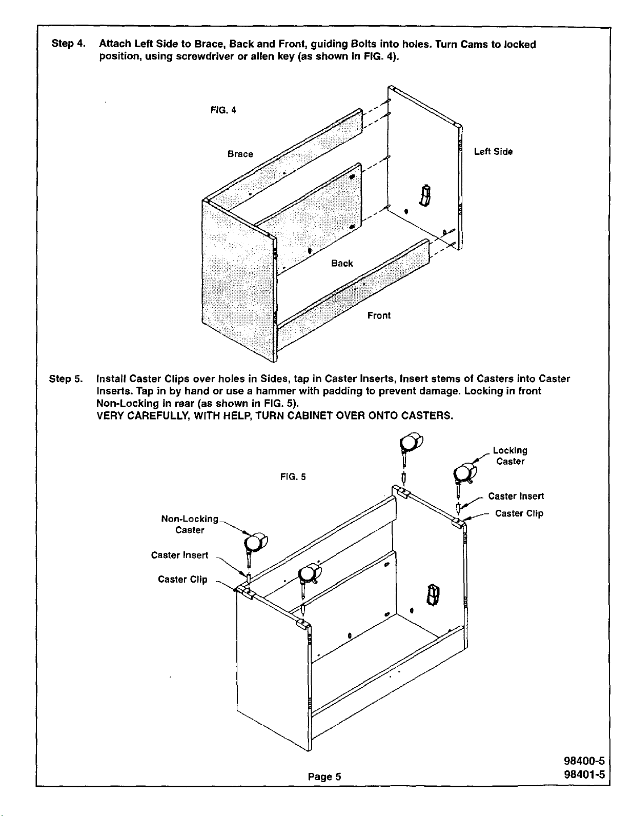
Step 4. Attach Left Side to Brace, Back and Front, guiding Bolts into holes. Turn Cams to locked
position, using screwdriver or allen key (as shown in FIG. 4).
FIG. 4
Brace
Front
Step 5. Install Caster Clips over holes in Sides, tap in Caster Inserts, Insert stems of Casters into Caster
Inserts. Tap in by hand or use a hammer with padding to prevent damage. Locking in front
Non-Locking in rear (as shown in FIG. 5).
VERY CAREFULLY, WITH HELP, TURN CABINET OVER ONTO CASTERS.
Lea Side
Caster
Caster Insert
Caster Clip
--....
FIG. 5
_C L°cking
Caster
aster Insert
Caster Clip
98400-5
Page 5 98401-5
 Loading...