

Page 1
KenmorG
Range Hood
Use & Care / Installation Manual
Campana de cocina
Manual de uso y cuidado / instalación
Models 233.50303200 (30” wide / 76,2 cm de ancho)
Modelos 233.50363200 (36” wide / 91,4 cm de ancho)
Page 2

READ AND SAVE THESE INSTRUCTIO
WARNING WARNING
SUITABLE FOR USE IN HOUSEHOLD
COOKING AREA.
TO REDUCE THE RISK OF FIRE, ELECTRICAL
SHOCK, OR INJURYTO PERSONS, OBSERVE
THE FOLLOWING;
1. Use this unit only in the manner intended by
the manufacturer. If you have questions, confact the manufacturer at the address or tele
phone number listed in the warranty.
2. Before servicing orcleaning unit, switch power
off at service panel and lock service panel to
prevent power from being switched on
accidentaliy. When the service disconnecting
means cannot be iocked, securely fasten a
prominent warning device, such as a tag, to
the sen/ice panel.
3. Installation work and electrical wiring must be
done by a qualified person(s) in accordance
with ali appiicabie codes and standards, includ
ing fire-rated construction codes and stan
dards.
4. Sufficient air is needed for proper combustion
and exhausting of gases through the flue (chim
ney) of fuel burning equipment to prevent
backdrafting. Follow the heating equipment
manufacturer’s guidelines and safety stan
dards such as those published by the National
Fire Protection Association (NFPA), and the
American Society for Heating, Refrigeration
and Airconditioning Engineers (ASHRAE), and
the local code authorities.
5. When cutting ordrilling info wall or ceiling, do
not damage electrical wiring and other hidden
utilities.
6. Ducted fans must always be vented to the out
doors.
7. Do not use this unit with any solid-state speed
control device.
8. To reduce the risk of fire, use only steel
ductwork.
9. This unit must be grounded.
TO REDUCE THE RISK OF A RANGE TOP
GREASE FIRE:
A. Never leave surface units unattended at high settings.
Boiiovers cause smoking and greasy spillovers that
may ignite. Heat oils slowly on low or medium settings.
B. Always turn hood ON when cooking at high heat or
when cooking flaming foods.
C. Clean ventilating fans frequently. G rease should not
be ailowed to accumulate on fan or filter.
D. Use proper pan size. Always use cookware appropriate
forthe size of the surface element.
TO REDUCE THE RISK OF INJURY TO PER
SONS IN THE EVENT OF A RANGE TOP
GREASE FIRE, OBSERVE THE FOLLOWING:*
1. SMOTHER FLAMES with a close-fitting lid,
cookie sheet, or metal tray, then turn off the
burner. BE CAREFULTO PREVENT BURNS.
If the fiâmes do not go out immediately, EVACU
ATE AND CALL THE FIRE DEPARTMENT.
2. NEVER PICK UP A FLAMING PAN-You may
be burned.
3. DO NOT USE WATER, including wet dishcloths
or towels - violent steam explosion will result.
4. Use an extinguisher ONLY if:
A. You know you have a Class ABC extin
guisher and you already know how to op
erate it.
B. The fire is small and contained in the area
where it started.
C. The fire department is being called.
D. You can fight the fire with your back to an
exit.
* Based on “Kitchen Fire Safety Tips” pub
lished by NFPA.
CAUTION
be sure to duct air outside. Do not vent exhaust
air into spaces within wails or ceilings or into
attics, crawl spaces, or garages.
2. Take care when using cleaning agents or
detergents.
3. Avoid using food products that produce flames
under the Range Hood.
4. For general ventilating use only. Do not use to
exhaust hazardous or explosive materials and
vapors.
5. To avoid motor bearing damage and noisy and/
or unbalanced impellers, keep dry wall spray,
construction dust, etc. off power unit.
6. Your hood motor has a thermal overload which
will automatically shut off the motor if It becomes
overheated. The motor will restart when it cools
down, if the motor continues to shut off and
restart, have the hood serviced.
7. For best capture of cooking impurities, the
bottom of the hood should be a minimum of 24"
and a maximum of 30" above the cooking sur
face.
8. Two installers are recommended because of the
iarge size and weight of this hood.
9. Please read specification label on product for
further information and requirements.
> properly«
Page 3
INSTALL BACKSPLASH (OPTIONAL)
If optional backsplash is used, attach it to the
finished wall. Secure hood mounting bracket
to the backsplash and omit wall framing
described below.
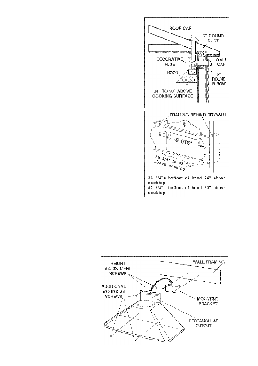
INSTALL THE DUCTWORK
NOTE: To reduce the risk of fire, use only
metal ductwork.
between the hood and the outside.
2. A straight, short duct run will allow the hood
to perform most efficiently.
3. Long duct runs, elbows, and transitions will
reduce the performance of the hood. Use
as few of them as possible.
4. Install a roof or wall cap. Connect 6" round
metal ductwork to cap and work back to
wards hood location. Use duct tape to seal
the joints between ductwork sections.
run1. Decide where the ductwork will
INSTALL MOUNTING BRACKET
1. Construct wood wall framing that is flush
with interior surface of wail studs.
Make sure:
a) the framing Is centered over installation location.
b) the height of the framing will allow the mounting bracket to be secured to the
framing within the dimensions shown.
After wall surface is finished, secure mounting bracket to framing using dimensions
2.
shown.
INSTALL THE HOOD
1. Hang the hood from the bracket through the rectangular cut-out on the back of
the hood. Cut-out is
larger than the bracket to
allow for horizontal
adjustment. The bottom of
the hood should be 24"
to 30" above the cooking
surface.
2. Height adjustment
screws provide vertical
adjustment.
3. Secure the hood with
additional mounting
screws. Use drywall
anchors, provided, if wall
studs or framing are not
available.
Page 4
WIRING
Note: This range hood must be properly
grounded.The unit should be installed by a
qualified electrician in accordance with all
applicable national and local electrical
codes.
GROUNDING INSTRUCTIONS
This appliance must be grounded. In the
event of an electrical short circuit, grounding
reduces the risk of electric shock by providing
an escape wire for the electric current. This
appliance Is equipped with a cord having a
grounding wire with a grounding plug. The
plug must be plugged into an outlet that is
properly installed and grounded.
WARNING - Improper grounding can result In a risk of electric shock.
Consult a qualified electrician if the grounding Instructions are not completely
understood, or if doubt exists as to whether the appliance is properly grounded.
Do not use an extension cord. If the power supply cord is too short, have a qualified
electrician install an outlet near the appliance.
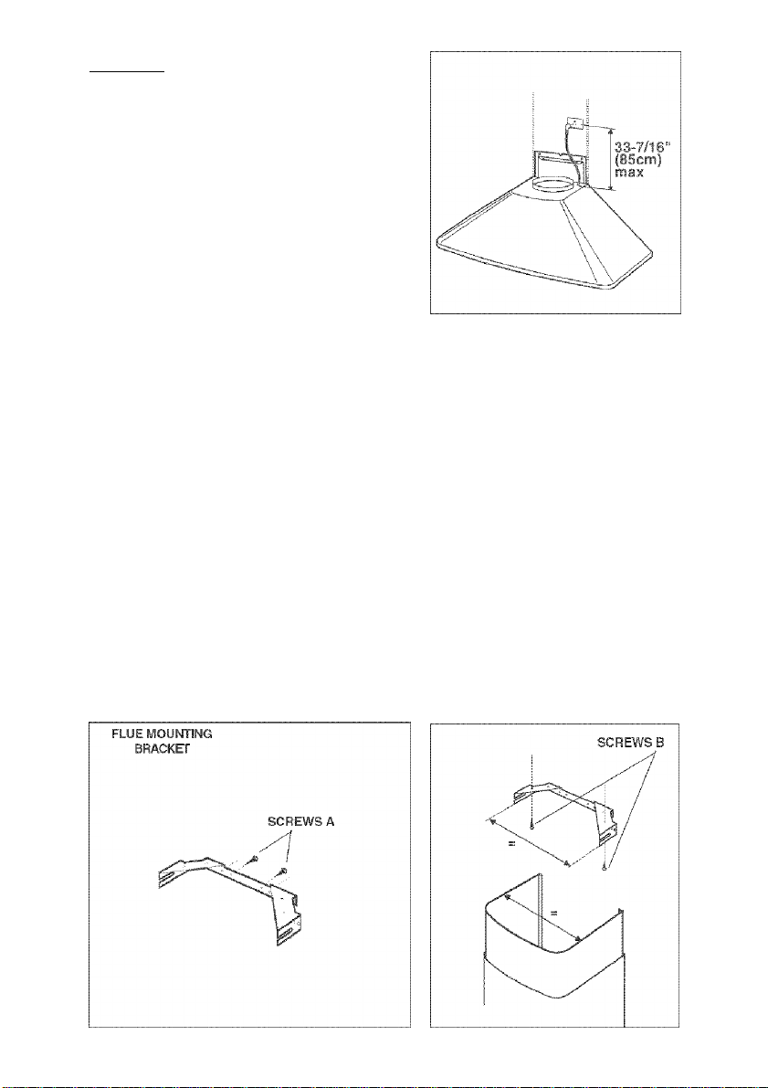
Set the elecfrical power supply within the space covered by the decorative flues.
Position the power socket at a maximum distance of 33-7/16” (850 mm) from where
the lead exits from the hood {see illustration alongside). Make sure this does not
interfere with the bracket fastening area or with the decorative pipe (where the flue
touches the wail).
Fit the plug into the power socket.
CONNECT DUCTWORK
Adjust the width of the flue mounting bracket using screws (A) Indicated in Figure.
Use screws (B) and wall anchors to secure flue mounting bracket to the ceiling as
shown.
Page 5
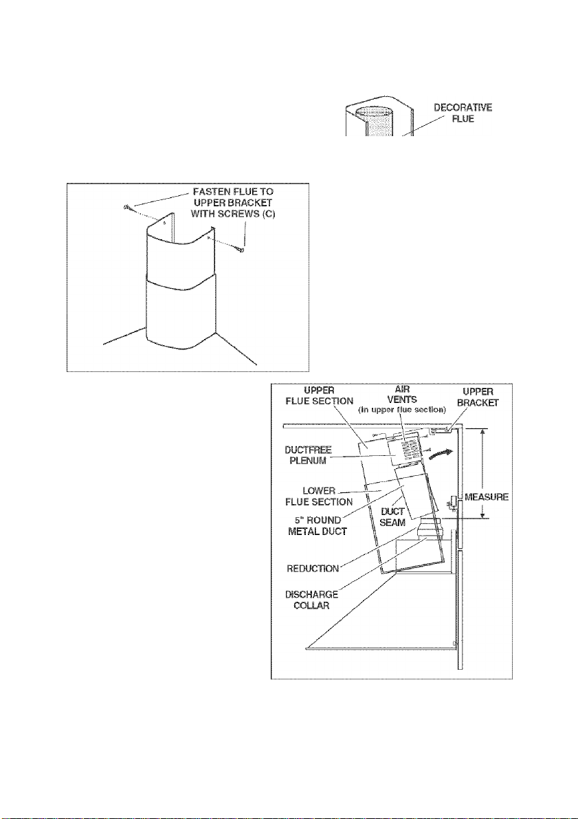
Ducted Configuration
1. Use 6" round metal duct to connect the
duct collar on the hood to the ductwork
above.
2. Use duct tape to make all joints secure
and air tight.
3. Insert the decorative flues setting them on
the hood.
4. Extend the upper flue to the ceiling and
secure with the 2 screws (C).
-DUCTTAPE
. 6" ROUND
METAL DUCT
Ductfree Configuration
1. Turn upper flue section upside
down so air vents are at the top.
Slide upper flue section into
lower flue section.
2. Connect the ductfree plenum to
the upper flue section with (4) flat
head screws (supplied).
3. Install the reduction on the
discharge collar.
4. Measure the distance from the
top of the reduction to the ceiling.
Cut a length of 5" round metai
duct 5" shorter than this
dimension.
5. Fit duct section over the ductfree
plenum. For best fit, make sure
duct seam is toward the front.
6. Set duct/flue assembly on hood
with top tilted away from wall.
Reach around flue to engage
bottom of duct with discharge
collar on hood. Tilt flue up against wall. Duct seam can be cut to length If necessary.
7.
Extend the upper flue to the ceiling and secure with the 2 screws (C).
Page 6
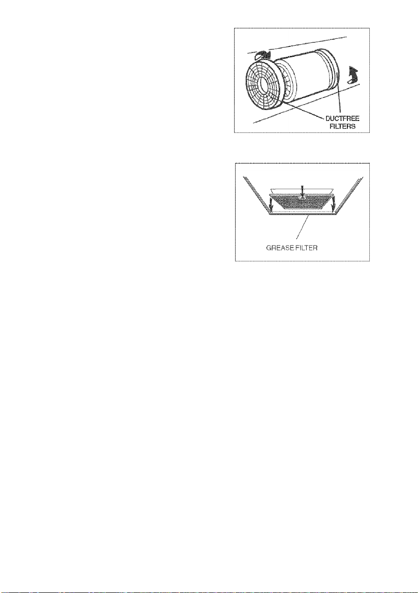
DUCTFREE FILTER
INSTALLATION
1. Ductfree filter kit (B03300487) is included.
2. Position the filters over the blower.
3. Rotate to lock filters in place.
MAINTENANCE
Proper maintenance of the Range Hood will
assure proper performance of the unit.
Grease Filter
The grease filter should be cleaned fre
quently. Use a warm detergent solution.
Grease filter is dishwasher safe.
Remove filter by pushing filter towards the
back of hood and rotating filter downward.
Ductfree Filters
The ductfree filters should be changed every 6 months. Rotate the filters to remove
and replace.
Hood Cleaning
Stainless steel is one of the easiest materials to keep clean. Occasional care will help
preserve its fine appearance.
Cleaning tips:
• Hot water with soap or detergent is all that is usually needed.
• Follow all cleaning by rinsing with clear water. Wipe dry with a clean, soft cloth to
avoid water marks.
• For discolorations or deposits that persist, use a non-scratching household cleanser
or stainless steel polishing powder with a little water and a soft doth.
• For stubborn cases, use a plastic scouring pad or soft bristle brush together with
cleanser and water. Rub lightly in direction of polishing lines or "grain" of the
stainless finish. Avoid using too much pressure which may mar the surface.
• DO NOT allow deposits to remain for long periods of time.
• DO NOT use ordinary steel wool or steel brushes. Small bits of steel may adhere
to the surface causing rust.
• DO NOT allow salt solutions, disinfectants, bleaches, or cleaning compounds to
remain in contact with stainless steel for extended periods. Many of these com
pounds contain chemicals which may be harmful. Rinse with water after expo
sure and wipe dry with a clean cloth.
Painted surfaces should be cleaned with warm water and mild detergent only.
Page 7

OPERATION
Controls
The hood is operated using the slide controls
under the bottom of the hood.
The light switch turns the lamps on and off.
The blower switch makes it possible to select
the motor operating speed. Position 0: motor
off.
The pilot lamp lights up whenever the blower
is on.
LIGHT BULBS
This range hood requires two 40-Watt light
bulbs (included).
ALWAYS SWITCH OFF THE ELECTRICITY
SUPPLY BEFORE CARRYING OUT ANY
OPERATIONS ON THE APPLIANCE.
To change bulbs:
1. Remove the screw securing the light fitting.
2. Replace with light bulbs of the same type.
CAUTION: BULB MAY BE HOT!
LIGHT
SVWTCH
BLOWER
SWITCH
Page 8

WARRANTY
If within 1 year from the date of installation, any part of this range hood fails to
function properly due to a defect In material or workmanship, Sears will repair
the part or furnish and install a new part, free of charge.
FULL 30-DAY WARRANTY ON FINISH ON PAINTED OR BRIGHT METAL
PARTS
If within 30 days from the date of installation, the finish on any painted or bright
metal parts of this range hood Is defective in material or workmanship, Sears
will furnish and install a new part, free of charge.
WARRANTY SERVICE IS AVAILABLE BY CONTACTING THE NEAREST
SEARS SEVICE CENTER/DEPARTMENT IN THE UNITED STATES.
This warranty applies only while this product is in use in the United States. This
warranty gives you specific legal rights and you may have other rights which
vary from state to state.
Sears, Roebuck and Co., Dept 817WA, Hoffman Estates, IL 60179
Page 9

LEA Y CONSERVE ESTAS INSTRUCCIONE
ADVERTENCIA
INDICADO PARA EL USO EN COCINAS
DOMÉSTICAS.
PARA EVITAR EL RIESGO DE INCENDIO,
CORTOCIRCUITO O DAÑO PARA LAS
PERSONAS, OBSERVE ATENTAMENTE LAS
SIGUIENTES NORMAS:
1. Use esta unidad solamente de la manera indicada por
el fabricante; si tiene dudas, póngase en contacto con
éste a ía dirección o teléfono indicados en la garantía.
2. Antes de hacer una revisión o de limpiar ia unidad,
desconéctela de la red para evitar que se encienda de
manera accidental. En el caso de que éste no pueda ser
desacti-vado, se indicará en la placa de caraote-risticas.
3. El montaje y ia instalación eléctrica debe hacerlos un
técnico especializado siguiendo las normas estándare
incluyendo aqueiias de construcción anti incendio.
4. Necesita aire suficiente para una apropiada combustión
y escape de gases a través del tubo de! depósito de
quema de combustible. Para evitar que el humo aspirado
vuelva a la cocina, siga las directivas del fabricante y
las normas estándar de siguridad así como las normas
pubiicadas por la Asociación de prevención de incendios
(NFPA)yla Socie-dad americana de especialistas en
cale-facción, refrigeración y aire acondicionado y además
ias normas de las autoridades locaíes.
5. Hacer un corte o un taladro en !a pared o en ei techo no
debe dañarla instalación eléctrica u otras instaíaciones
ocultas en ia pared.
6. Los conductos ventiladores deben siempre desalojar al
exterior.
7. No use esta unidad con dispositivo de control de la
velocidad a estado sólido.
8. Para evitar el riesgo de incendio, use solamente
conductos de metal,
9. Esta unidad tiene que ser conectada a tierra.
PARA EVITAR EL RIESGO DE FUEGO POR ALTO
NIVEL DE GRASA:
A. Nunca abandone ios quemadores con ei fuego aito.
La cocción causa humo y restos de grasa que pueden
arder. Caliente el aceite a fuego medio o bajo.
B. Encienda siempre ia campana cuando cocine a fuego
alto o cuando cocine alimentos fácilmente
inflamables.
C. Limpie con frecuencia los ventiladores. Nosedebe
acumular grasa en ei ventilador o en el filtro.
D. Usa el tamañp de cazuela apropiado. Use siempre
Litensiiíos de cocina de tamañoy material adecuados.
ADVERTENCIA
PARA EVITAR EL RIESGO DE DANOS A
PERSONAS EN CASO DE FUEGO POR ALTO
NIVEL DE GRASA, TENGA EN CUENTA LO
SIGUIENTE:*
1. SOFOQUE LA LLAMA con unatapaderaapropiada, una
bandeja metálica ó un utensilio de cocina que pueda
cubrirla, después, apague el quemador. ACTÚE CON
PRECAUCION PARA EVITAR QUEMA-DURAS. Si la
llama nose extingue inmedia-tamente, SALGA Y LLAME
A LOS BOMBE-ROS,
2. NUNCA COJA UNA SARTEN EN LLAMAS, porque corre
el riesgo de quemarse.
3. NO USE AGUA ni paños o toallas húmidas porque puede
provocarse una vioíenta humareda.
4. Use un extintor SOLAMENTE si:
A. Posee un extintor de clase ABC y sabe
perfectamente cómo usarlo.
El fuego es pequeño y está controlado en ei mismo
B.
sitio en que empezó.
Ha llamado con anterioridad a los bomberos.
C.
Puede combatir el fuego retrocediendo hacia la
D.
salida.
* Basado en "Seguridad antituego en ía cocina” publicado
por NFPA.
ADVERTENCIA
1. Para reducir e! riesgo de incendios y para evacuar
correctamente ios humos, asegurarse de haber realizado
una conducción del aire hasta el exterior. No expulsar
los humos en espacios cerrados por paredes o techos,
áticos, espacios angostos o garajes.
2. Prestar la máxima atención al utilizar productos de
limpieza o detergentes.
3. Evitar el uso de productos alimentarios que puedan
inflamarse bajo la campana.
4. Sólo para ventiiación total. No use gases de escape
peligrosos o materiaies y vapores explosivos.
5. Para evitar daños en el funcionamiento del motor e
impulsores ruidosos y/odesequi-íibrados, mantenga
alejados de la unidad de encendido pulverizadores en
secoopoívo.
6. El motortiene un nivei de sobrecarga térmica que apaga
automáticamente ei motor cuando se ha recalentado
excesivamente. El motor se pone de nuevo en
fincionamento cuando ia temperatura baja. Si el motor
comienza a encenderse y a apagarse, deberá hacer
una revisión de éste.
7. Para limpiar mejor las impurezas al cocinar, la parte
inferior de la campana debe estar a una temperatura
mínima de 24 grados y máxima de 30 grados por debajo
de íatemperatLire de la zona de cocción.
8. Debido a su gran tamaño y peso, se recomienda su
montaje por parte de dos técnicos esperializados.
9. Se recomienda leer la placa de caracte-risticas dei
producto para ulterior información.
Page 10

INSTALACION DEL
SALPICADERO (OPCIONAL)
Si se usa un modelo con salpicadero, sujete
primero éste a la pared. Asegure los tomillos de
montaje de la campana al salpicadero y
prescinda de la estructura de montaje en la
pared abajo descrita.
INSTALACION DEL TUBO DE
EXTRACCION
NOTA: para evitar el riesgo de incendio, use
solamente material de metal,
1. Decida donde va a colocar el tubo de
extracción entre lacampanayla parteexterior.
2. Un recorrido de tubo corto y recto permitirá a
!a campana funcionar de manera más eficaz.
3. Los recorridos largos de tubo,codosy manguitos
impiden el buen funcionamiento de la campana.
Use el menor número de ellos posible.
4. Instale una cubierta ó una tapa. Una el tubo
de metal de 6” (15cm) de diámetro a la
cubierta y retroceda hasta la posición de la
campana. Use une cinta para precintar las
juntas entre las partes del entubado.
________________
UBIERTA DEL
24" (61 cm) A 30” (76cm)
PÔR ENCIMA
DE LA ZONA DE
COCCSON
ESTRUCTURA DE MADERA EN LA PARED
ai
y
De
Je
3'4
Por
f53.Sc.
INSTALACION DE LOS
SOPORTES PARA EL
36-3/4"{93,5cm) = si la distancia entre la
campaneé y la zona de cocción es de 24’''(61crn).
42-3/4“(10gciTi)=: si lad istancia entre la campana
y la zona de cocción es de SO" (76cm).
MONTAJE____________________
1. Construya una estructura de madera en la pared que quedará nivelada con la parte
interior de los tacos en la pared. Asegúrese de que;
a) La estructura se encuentra centrada por encima de la Instalación del tubo.
b) La altura de la estructura permite fijar los soporta para el montaje en esta estructura
siguiendo las dimensiones indicadas.
2. Una vez que la superficie de la pared esté acabada, sujete los soportes para el
montaje siguiendo las dimensiones indicadas.
INSTALACION DE
LA CAMPANA
1. Cuelgue la campana del
soporte por el agujero
rectangulare situado
detrás de la campana. El
agujero es más grande
que el soporte para
permitir el ajuste en
horizontal.
La parte inferior de la
campana debe estar a
una distancia de 24”
{61 cm) ó 30” (76cm) por
encima de la zona de
Page 11

cocción.
2. Los tomillos para la regulación de la altura permiten un ajuste en vertical.
3. Sujete la campana con tornillos para montaje adicionales. Use escarpias si no
dispone de tacos o de la estructura de soporte en madera.
INSTALACION ELECTRICA
Nota: Este tipo de campana tiene que ser
conectada a tierra cuidadosamente. La
unidad debe instalarla un técnico
electricista siguiendo las normas
nacionales y locaies,
INSTRUCCIONES DE CONEXIÓN A
TIERRA
Este aparato se debe conectar a tierra. En
caso de cortocircuito, la conexión a tierra
reduce el riego de electrocución ya que
posee un hilo de descarga a tierra para la
corriente. Este aparato está equipado con
un cable que posee un hilo de toma de tierra
con una clavija de tierra. La clavija se debe
conectar a un enchufe instalado correctamente y conectado a tierra.
ADVERTENCIA- una conexión a tierra Incorrecta puede provocar riesgos de
electrocución.
Consulte a un electricista calificado si no se entienden o si existe alguna duda
sobre la correcta conexión a tierra.
No utilice un cable de prolongación. Si el cable proporcionado es demasiado
corto, póngase en contacto con un electricista calificado para que instale un
enchufe cerca del aparato.
Conecte la alimentación eléctrica en el espacio cubierto por el tubo decorativo.
Coloque el enchufe a una distancia máxima de 33-7/16” (85 cm) desde el cable de
la campana (véase figura adjunta). Asegúrese de que no interfiera con el área de la
abrazadera de sujeción o con el tubo decorativo (donde ei tubo decorativo toca con
la pared).
Conecte la clavija al enchufe.
ENTUBADO DE CANALIZACION
Regule la anchura del tubo montando la abrazadera con los tornillos (A) como se
puede observar en la Figura.
Use tornillos y escarpias para fijar al techo el
soporte para el montaje del tubo como se
indica.
_________________________
Page 12

Configuración con tubo
1. Use un tubo de melai de 6” (15cm) de
diàmetro para unir el collar de descarga
que se encuentra encima de la campana
al tubo de extracción situado arriba.
2. Use cinta para ajustar todas las junturas y
que quede hermético.
3. Introduzca el tubo decorativo conectándolo
en la campana.
4. Extienda la parte superior del tubo
decorativo hacia el lecho y sujétela con 2
tornillos (C).
Configuración sin tubo
1. Dé la vuelta a la parte superior
del tubo de manera que las
rejillas de salida del aire estén en
la parte superior. Haga deslizar la
parte superior del tubo hasta
alcanzar la parte inferior de éste.
2. Una el respiradero de aire con la
parte superior del tubo por medio
de cuatro tornillos con cabeza
plana (adjuntos).
3. Instale el reductor en el collar de
descarga.
4. Mida la distancia desde la parte
superior del reductor hasta el
techo. Corte a una distancia de 5"
(12,5 cm) alrededor dei tubo de
metal 5" más corto que su medida.
5. Instale el tubo en el orificio. Para
una mejor instalación, asegurarse
de que la juntura del tubo se
encuentre en la parte frontal.
6. Instale el tubo en la campana con
la parle superior inclinada con respecto a la pared. Alargar el borde del tubo para
sujetarlo a la parte inferior del tubo mediante el collar de descarga en la campana.
Inclinar la parte superior del tubo decorativo contra la pared. La juntura del tubo
se puede cortar longitudinalmente si es necesario.
7. Extendienda la parte superior del tubo hacia el techo y sujétela con 2 tornillos
(C).
Page 13

INSTALACION DOS FILTROS
(CONFIGURACION SIN TUBO)
1. El juego de filtros de ricambio de aire
(B03300487) es adjunto.
2. Instale los filtros sobre el aspirador.
3. Gire los filtros para ajustarlos en su sitio.
MANTENIMIENTO
Un mantenimiento adecuado de la campana
asegura el funcionamiento correcto dei
aparato.
Filtro antigrasa
El filtro antigrasa debe limpiarse a menudo.
Use un detergente que no sea fuerte.
El filtro antigrasa se puede meter en el
lavavajillas. Extraiga el filtro tirando de ello hacia atrás de la campana y girándolos
hacia abajo.
Filtros (configuración sin tubo)
Los filtros deben cambiarse cada seis meses. Gire los filtros para desenroscarlos y
cambiarlos.
Limpieza de la campana
El acero inoxidable es uno de los meteriales más fáciles de limpiar, pero sería
aconsejable un especial cuidado en su uso para mantenerla en buen estado. La
campana se puede limpiar de las siguientes maneras:
• Agua callente con jabón o detergente es la mejor manera para limpiarla.
• Aclárela con agua corriente, séquela con un paño suave y limpio para evitar las
huellas que deja el agua.
• Para las manchas o restos de grasa que persistan, use un producto químico
doméstico que no raye ó un limpiador para acero inoxidable con poca agua y un
paño suave.
• Si las manchas persisten, use un estropajo y un cepillo de cerdas suaves con un
producto limpiador y agua. Frote suavemente en el sentido del pulido o de las
“vetas” del remate del inoxidable. No apriete demasiado porque podría dañar la
superficie.
• No deje que las manchas se acumulen durante mucho tiempo.
• No use utensilios o cepillos de acero. Pequeñas partículas de acero pueden
adherirse y oxidarse.
• No use soluciones salinas, desinfectantes, lejías, o productos de limpieza que
permanezcan en contacto con el acero inoxidable durante largos periodos de
tiempo. Muchos de estos productos contienen componentes químicos que podrían
resultar nocivos. Aclare con agua y seque con un paño limpio.
Las superficies lacadas deben limpiarse solamente con agua tibia y detergente no
muy fuerte.
Page 14

FUNCIONAMIENTO
Mandos
La campana se controla mediante los mandos
corrrederos situados en la parte inferior de la
misma.
El interruptor da luz enciende y apaga las
lámparas.
El interruptor dei aspirador: regula la
velocidad de trabajo del motor. Posición 0:
motor apagado.
El piloto se enciende cuando ei aspirador está
funcionando.
LAMPARAS
Este tipo de campana necesita 2 lamparas
Tipo 40 WATT (adjuntos).
ANTES DE PROCEDER A CUALQUIER
OPERACIÓN, ES NECESARIO
DESCONECTAR EL APARATO.
Para cambiar las lámparas:
1. Quite el tornillo que sujeta las lámparas.
2. Sustituir con lámparas del mismo tipo.
ATENCIÓN: LAS LÁMPARAS PUEDEN
ESTAR CALIENTES.
INTERRUPTOR
DA LUZ
INTERRUPTOR
DEL ASPIRADOR
Page 15

GARANTIA
Si dentro de 1 año de la fecha de la instalación, cualquier parte de esta campana
de cocina deja de funcionar en forma apropiada debido a defecto en el material
o la mano de obra, Sears reparará la pieza afectada o proveerá e instalará una
pieza nueva libre de cargo.
GARANTIA COMPLETA DE 30 DÍAS EN EL ACABADO EN PIEZAS
METÁLICAS PINTADAS O ABRILLANTADAS
Si dentro de 30 días de la fecha de la instalación, el acabado de cualquier
parte metálica pintada o abrillantada perteneciente a esta campana de cocina
aparece con defecto en el material o la mano de obra, Sears proveerá e
instalará una pieza nueva übre de cargo.
EL SERVICIO DE GARANTIA SE OBTIENE PONIÉNDOSE EN CONTACTO
CON EL CENTRO DE SERVICIO O DEPARTAMENTO SEARS MÁS
CERCANO EN LOS ESTADOS UNIDOS,
Esta garantía es valedera únicamente si este producto se tiene en uso dentro
de los Estados Unidos. Esta garantía le confiere derechos legales específicos
y Ud. puede tener además otros derechos que varían de estado a estado.
Sears, Roebuck and Co., Dept. 817WA, Hoffman Estates, IL 60179
Page 16

SERVICE PARTS
MODELS 233.50303200 / 233.50363200
KEY NO. PART NO, DESCRIPTION
9 B08087292 Grease Filter
14 B02300233 Motor Capacitor
16 BE3244974 Electrical Box Support
26 B02300264 Lamp Bulb
28 B02300280 Lampholder
29 B03200618 Light Diffuser
45 BW0000019 Blower
48 B02310177 Motor
49 B03295076 Blower Wheel
53 B03202007 Rubber Washer
58 B03295018 Outlet Reduction
60 B02300248 Feeder Cable
86 B08088378 Outlet Flange
114 B032904990 Runner Wires
118 BE3343338 Decorative Flue Bottom
119 BE3343339 Decorative Flue Top
120 B08091335 Flue mounting Bracket
122 B03295016 Ductfree Plenum
145 B032920170 Feeder cable connection Box
146 B032920180 Feeder Cable Connection Box Cover
147 BR2300132 Junction Clamp
151 B032920200 Electrical Box Wires Stop
152 B03292200 Feeder Cable Clamp
165 B03295029 Electrical Box Switch Assy.
165 B03295008 Electrical Box Capacitor
167 B03295030 Electrical Box Cover
168 B03295031 Feeder Cable Cover
195 BE3343337 Bracket
196 B02011113 Reflector
228 B08086255 Controls Board
229 B03201014 Warning lamp
238 B03295032 Motor Switch Button
241 B03295033 Light Switch Button
407 BE3344985 Blower Support Bracket
477 B03295034 Closing
*
*
B06001983 Blower Assembly (Includes Key Nos. 45, 48,
49, 53)
B03300487 Ductfree filters KIT (Includes Nos.2 filters)
Not shown assembled.
Page 17

LISTA DE PIEZAS DE RECAMBIO
MODELOS 233.50303200 / 233.50363200
CÓD. N. pieza N. DESCRIPCIÓN
9 B08087292 Filtro antigrasa
14 B02300233 Condensador
16 BE3244974 Soporte de la caja de instalación eléctrica
26 B02300264 Lámpara
28 B02300280 Soporte de la lámpara
29 B03200618 Tapa de la lámpara
45 BW0000019 Convoyador
48 B02310177 Motor
49 B03295076 Manilla de motor
53 B03202007 Almohadilla antivibraziones
58 B03295018 Reducción
60 B02300248 Cabos
86 B08088378 Conector del aire
114 B032904990 Sujeta cabos
118 BE3343338 Tubo decorativo inferior
119 ВЕ334333Э Tubo decorativo superior
120 B08091335 Soporte de montaje del tubo
122 B03295016 Desviador del aire
145 B032920170 Caja cabos alimentación
146 B032920180 Tapa de la caja cabos alimentación
147 BR2300132 Terminal
151 B032920200 Sujeta cabos
152 B03292200 Sujeta cabos
165 B03295029 Caja de instalación eléctrica
165 B03295008 Caja de instalación eléctrica
167 B03295030 Tapa de la caja de instalación eléctrica
168 B03295031 Tapa cabos alimentación
195 BE3343337 Soporte
196 B02011113 Reflector
228 B08086255 Base de los mandos
229 B03201014 Piloto
238 B03295032 Mando motor
241 B03295033 Mando iluminación
407 BE3344985 Soporte convoyador
477 B03295034 Sierre
*
B06001983 Conjunto motor {Incluye ios N. 45, 48,
49, 53)
B03300487 Conjunto filtros configuración sin tubo
(Incluye N.2 filtros)
Se encuentran por separado.
Page 18

SERVICE PARTS - LISTA DE PIEZAS DE RECAMBIO
MODELS 233.50303200 / 233.50363200
C3«~ /“fe™
O-
® 26
29
Page 19

íGl|SÍ!iÍR
For repair of major brand applicances in your own home ...
no matter who made it, no matter who sold it!
1-800-4-MY-HOME®
(1-800-469-4663)
www.sears.com
For repair of carry-in products like vacuums, lawn equipment, and
electronics, call for the nearest Sears Parts and Repair Center.
1-800-488-1222 Anytime, day or night
www.sears.com
For the replacement parts, accessories and owner’s manuals
that you need to do-it-yourself, call Sears PartsDirect®'^!
1-800-366-PART 6 a.m. -11 p.m., 7 days a week
(1-800-366-7278) (U.S.A. only)
www.sears.com/partsdirect
To purchase or inquire about a Sears Service Agreement
or Sears Maintenance Agreement:
1 -800-827-6655 (U.S.A.) 1 -800-361 -6655 (Canada)
7 a.m.-5 p.m. 9 a.m.-8 p.m. EST, M-R
CST, Mon. - Sat. 4 p.m. Sat.
Anytime, day or night
(U.S.A. and Canada)
www.searsxa
Para pedir servicio de reparación a
domicilio, y para ordenar piezas:
1-888-SU-HOGAR“
(1-888-784-6427)
Au Canada pour
service en français
1-888-LE-FOYER“®
(1-800-533-6937)
www.sears.ca
HomeCentnal
I Sears, Roebuck and Co.
I Registered Trademark / ™ Trademark / Service Mark of Sears, Roebuck and Co.
I Marca Registrada / ™ Marca de Fábrica / Marca de Servicio de Sears, Roebuck and Co.
' Marque de commerce / “ Marque déposée de Sears, Roebuck and Co.
Page 20

04306897
 Loading...