

158.17572
158.17560 158.17740
158.17570 158.17741
1S8.17S71
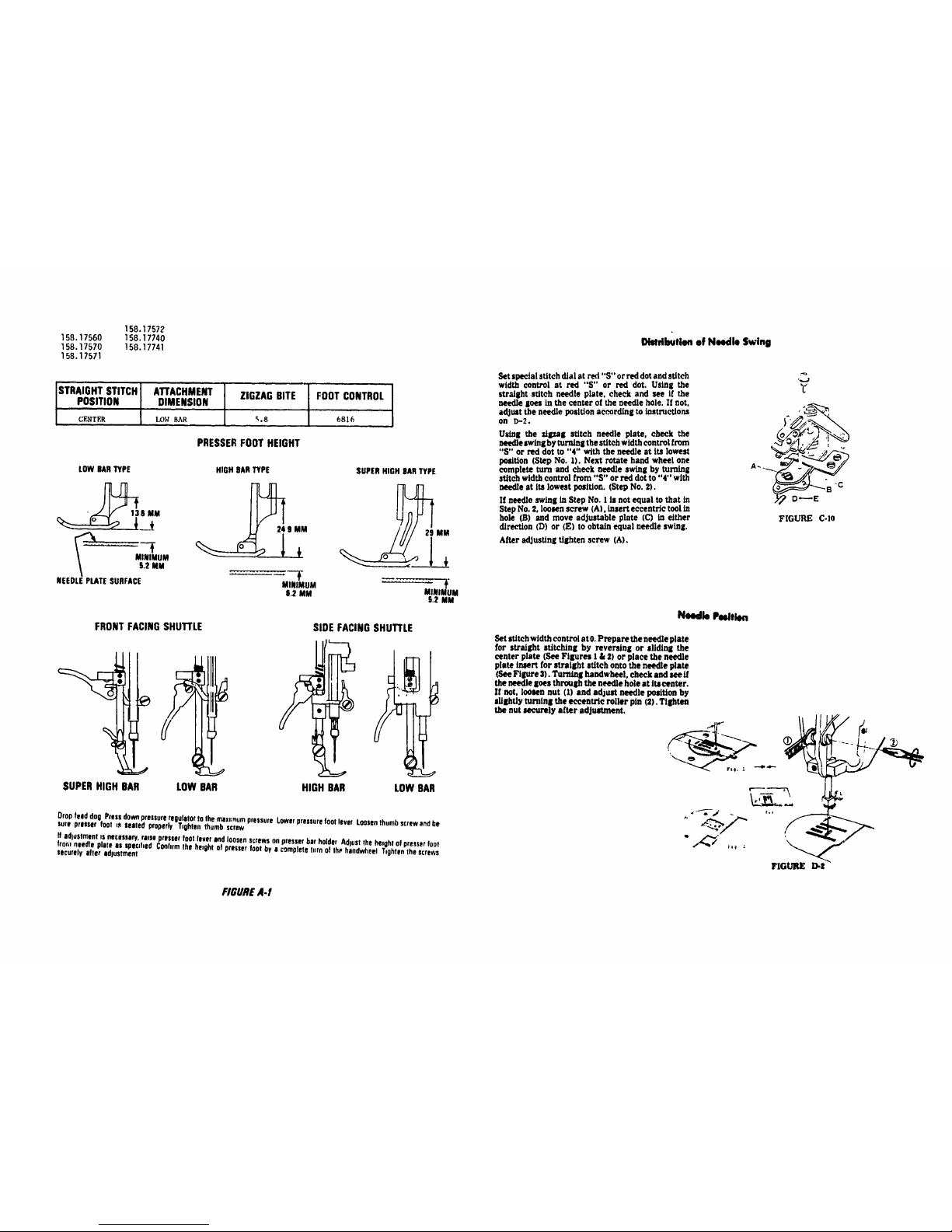
STRAIGHTSTITCH ATTACHMENT ZIGZAG BITE FOOTCONTROL
POSITION DIMENSION
ml
(;ENTER LO1€ BAR _,8 6816
ii
PRESSERFOOT HEIGHT
LOW BARTYPE
•_136 MM
MINIMUM
5.2 MM
NEEDLEPLATESURFACE
HIGHBARTYPE
24 S MM
MINIMUM
8.2 MM
SUPERHIGH OARTYPE
...... . NllOM
5.2 MM
FRONTFACINGSHUTrLE
SIDE FACINGSHUTrLE
SUPERHIGH BAR
LOW BAR HIGH BAR LOW BAR
Drop feed dog Pressdo_ pressureregulatorto the max,mumpressure Lowerpressurefoot lever Loosenthumbscrewend be
sure presser foot t,* seated properly Tighten thumbscrew
If adjustmentIs necessaw, raise presser foot leverandloosenscrews onpresserbar holder AdluSt the heightof presserfoot
fror,r needle plate as _oecd,ad Coohrmthe he,oht of presserfoot by a completeturn of the handwheel T,ghtenthe screws
securely after edlustment
Disldbuticm of Needle Swing
Set spe_al stitch dial at red "S" or ted dot and sUtch
width control at red "S" or red dot. Using the
straight stitch needle plate, check and see if the
needle Sees in the center of the needle hole. If not,
adjust the needle poslUon according to inst_eUons
on I)-2.
Us_g the _d_g stitch needle plate, check the
needle swing by turning the stitch width control from
"S" or red dot to "4" with the needle at Its lowest
pooit/on (Step No. l). Next rotate hand wheel one
complete turn =nd check needle swing by turning
stitch width control from "S" or red dot to "4"' with
needle st its lowest position. (Step No. Z).
If needle swins in Step No. I is not equal to that in
Step No. 2, loosen screw (A), insert eccentric tool in
hole (B) and move adjustable plate (C) in either
d/reetton (D) or (E) to obta/n equal needle swing.
After adjusting tighten screw (A).
,_..J
"8.c
FIGURE C-le
Needle Pedtlen
Set stitch width control at 0. Prepare the needle plate
for straight stitching by revers/ng or sliding the
center plate (See Figures l & 21 or place the needle
plate Insert for straight stitch onto the needle plate
(See Figure 3). Tur'n_g handwheel, check and see if
the needle goes through the needle hole at lteeenter.
If not, loosen nut (1) and adjust needle posit/on by
sUShtly turnlnl the eccentric roller pin (3). TlShten
the nut securely after adjustnlant.
FIGUREA-f
158.17560 I_IWwwIIIN I
158.17570
158.17571
158.17572
158.17740
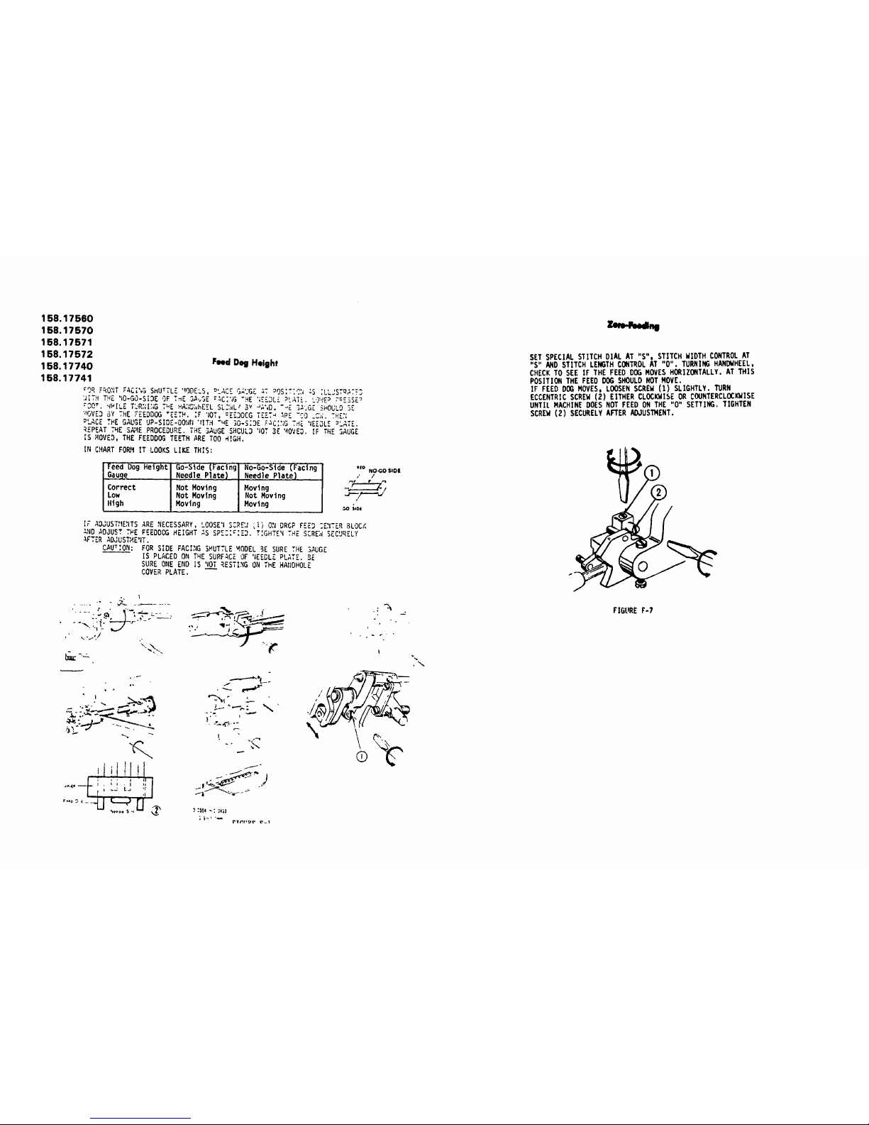
Feed Dog Height
158.17741
€OR F_O_IT PACT',&SHUTTLE '_ODE=S, _LACZ GAUGE _T _9S:T:_:I=S ;LLJSTRATT3
:JITHT_E 'IO-GO-SiOEOF T_E 3_._SE :4C;';G"_E ';€_DL_PLATE. LO'.!E_ PcE3SE_
_00". '_HILET_R_;I:;GThE HA:;_hE_L SL_LI 3v _;',D."_E ];'.GZ_OULO SE
'._OVE3BY THE ?EEDDOG "EZTH. IF 'lOT,:EE3DCG TEET_ _PE "CO _C_. THE_:
PLACE THE GAUGE UP-SIDE-DOWrl'IITH÷"E IO-S;3E F_C:_;GTHE 'EE_L[ _LATE.
REP{AT THE S_4E PROCEDURE. THE SAuGE SHCUL3 'lOT3E '40VED. IF THE SAUGE
IS MOVED, THE FEEDDOG TEETH ARE TOO _!GH.
IN CHART FORM IT LOOKS LIKE THIS:
Feed Dog Height Go-Side (Facing No-Go-Slde (Facing ,,oNO:OS,OI
Gauge Needle Plate) Needle Plate) ,' /
Correct Not Moving Moving .-_/
Low Not Moving Not Roving
High Moving Moving
I
_0 SiOi
I; ADJU T_I'S E.ITSARE NECESSARY, LOOSE'ISCRE:_ i) ON DRCP FEED :ENTER BLOCK
AND ADJUST THE PEEDDOG HEIGHT _S r"_':_
SP....... TIGHTE_ THE SCREW SECURELY
AFTER ADJUSW4E'IT.
T_
CAU ,ON: FOR SIDE FACI_IGSHUTTLE MODEL BE SURE THE SAUGE
IS PLACED ON THE SURFACE OF 'EEGLE PLATE. 5E
SURE ONE END IS 'lOTRESTING ON THE HAIIDHOLE
COVER PLATE.
., I
-.'_ _-.,--__.
-%
,i t!t!t
i * , I il
lll,(ll -- I = I I • I II
•..,,__.U<__,,ri'
"ltl+_i _ ,I i.i_
f
i:; ._' ""
r,..
I
+ ,w¢*_
/"
i'? ¢Zlll_ _--1
.\
SET SPECIAL STITCH DIAL AT "S". STITCH WIDTH CONTROLAT
"S" AND STITCH LENGTH CONTROLAT "0". TURNING HANDWHEEL,
CHECKTO SEE IF THE FEED DOG ROVESHORIZONTALLY. AT THIS
POSITION THE FEEO DOG SHOULDNOTROVE.
IF FEED DOGMOVES, LOOSENSCREW(1) SLIGHTLY. TURN
ECCENTRICSCREW(2) EITHER CLOCKWISEOR COUNTERCLOCKWISE
UNTIL MACHINE DOES NOT FEED ON THE "0" SETTING. TIGHTEN
SCREW(2) SECURELYAFTER ADJUS'ff4ENT.
FIGURE F-7

NEEDLE TIMING TO SHUTTLE
NEEDLE BAR HEIGHT
THE RADIAL TIMING GAUGESAND TEST PINS, AS
ILLUSTRATED BELOW, ARE AVAILABLE FROMDIVISION
92, SOURCE192. THE KIT IS IDENTIFIED AS
#69659° EACHGAUGEANO TEST PIN CAN ALSO BE
ORDEREDINDIVIDUALLY.
THIS KIT IS USED FOR SOURCE148 ANO 158
VERTICAL BOBBIN SEWING MACHINES.
RADIAL
TIMING GAUGE
#69894
RADIAL
TIMING GAUGE
#69892
RADIAL
TIMING GAUGE
#69893
TEST PIN
e69873
RADIAL
TIMING GAUGE
FIGURE G-I #69895
NEEDLETIMINGTOSHUTTLE
Donot attemptidlustmlntsotherthan thosespecdledm
thismanualH.byfollowingthe prescnbedprocedures.:t is
determinedthat| machineISoutof radialtime.handlepet
Bulletin S.R20
Radial Timing Gauge
Instructions
I Removenoodleandreplacectwth testpmwhichhasa
blunttip
2 Insertoorfoctradialtiminggaugeinto shuttlednvor
Usegaugemarked
Source158 FRONT70 FRONT700
Use FRONT700 marking
3 Set stitch controlat "0" or "S" (dependingonmodel
involved)
On machineswith 70 zigzagbite whichhave a left
needleotrelghtstitchposmon,conter the needle by ,%.
mnl_s of the stitchwdth control Use centerstrip
betweenrear feeddogsas a omdefor centenng the
4
needle
Sit needlepOSdioncontrolat centerfor modelswhich
haveth_scontrol
Rotatehandwheelslowlybyhand(SeeFrgure6 3# ) The
felt pm shouldcomebetweenthe correcttwo vemcal
linesIt theendof the counterclockwzserotationof the
gauge
Tocheckneedlebarheighf,continueto rotatehandwhool
slowlybyhand (SeeFigureG.3b)Atthelowestpus:hun
of the needleher.1heand ofthetestpinshouldcome
betMOn tWOhonzonteilineson the gauge
If necoseo_,,adluStneedlebarheight Loosenscrewon
noodlebarholderand adlust heighton the fist pm
DIMENSIONA
DIMENSIONB
FIGUREG-3

Needle €learance te Shulde
The Cf¢sran¢_ "'a.'" °'b." "c," _d the angle "d" are yew
critical po_ttlS ,n relatiOn tO fill needle t,mln 9 to shuttJe.
Hoverer. the_l _)omts _rl v,sual(y _terml_d by J$1_ the
Rjdlal Timing G,tugls.
NOTE:
No ad_ustm_t ,s allowed for °'Dmmlnslon _' for the
frcl_t.flcmg _uttle _|1, For adiu_r_nt for s(de_ut_e
n_dels. I_em rtfmr tO Fi_m G.3.
fd"_
h
158.17560
158.17570
158.17571
158.17572
158.17740
158.17741
Zigzag Synchronization
Set stitch widt_ control at maximum. Turning _e
handwheel, check and see if the needle side motion
on t.hestandard plane (0.03<J4inch above _e upper
surface of the needle plate) at both needle positions
come wl_ln _he engineenng lirni_ o! 0.01_1inch. I!
not, |oosen set screw _2) on the worm gear e_ther
_reetion. Tighten the screw (2) securely alter
adjustment.
iI_," ",'_l|
_ __ ..
,I i"
I 001311' 0 _O._m,
k
FIGURE I.l-!
\
*.\

Stmil_t Stitching
SET STITCH wIDTH CONTROL AT "S". TURNIkR_HANDWHEEL
SLOWLY, CHECKTO SEE IF THE NEEDLE SWINGS. IT SHOULD
NOT SWING. IF ADJUS'YMENT IS NECESSAR_ LOOSEN SCREW
(1) AND MOVE THE ZIGZAG WIDTH ARM (2) TO THE EXTREME
LEFT POSITION. TIGHTEN THE SCREW SECURELY AFTER
ADJUSTMENT.
FIGURE
Automatic Reverse Stitching
Stretch Stitch
Place the ._o. 21 pattern disc lnther_=Chlne. Set
the stitch width control at 4 andthestitch length
control ;K 6. Place a piece of folded paper Over
the Leed dogs. Check and see ff the forward and
reverse stitches are equal by zig sag stitcl_g
on the paper. If the pitch of the stitches in
reverse Is shorter or longer titan In forward,
loosen screw (B) and adJtUlt the plats (C) _ul
indicated. Tishten the screw securely alter
adJuJItment. FIGURE J-14
I-4
158.17560
158.17570
158.17571
158.17572
158.17740
158.17741
Automatic Mechanism
Cam and Follower Mechanism
If the specL_.l stitch dlal tar'lot be turned, Jt
may be due to _'_suff;ctent clearance between
the cam ;rod cam foUower. E.xcesswe clearance
however, w_ reSUlt m an trrelp'J!arpattern.
'1"oadjust {he mecn;n;sm _et the spechd ._tttch
d_tl between soy two sett_l:s. L_osen screw
_A), push operating plate (B) in dtrectzon (C),
move cLaw openmK plate (D) m direction E£),
then t_l_ten screw {A} wlth zlg/,_K width bracget
pin _F} held m d_recflon t_) _¢_inst lockerplate
(G).
Next set spec_l stltc_ d_al at oneof tour settings
and stitch width €ontro! at ,4). L_wer needle to
its lowest position. Check ,f needs moves to
the r_gbt when specl41 stitch dL_l is set between
each sc_tmg _nd _ It alolost touches the right
e_e ot the needle hole. [fneed_eh_ts the needJe
plate, refer to instructions or; distribution of
need _.e swing.
Check d zqrzaK cam follower moves w_thout
touchmK each btJfltom cam when spec_l stitch
Is turned clockwise or €ounterclockwise.
If it does not move props rl_. reler to instructions
on cam selector guide pla_e setting,
/
FIG[_RE K-I 3
A
B

Cam Selecter Guide Plate Setting
U the cam follower does not a_llrn with the cam
adJtmt In the _ollowinl_ manner.
For model IqSS0 Lnd 17560 heads, set special
stitch dial at blind stitch eettin¢. }'or model
17_70 - set special etitch dial at mencUng
,_ettinp.
Remove the cap on the backside of the machine
arm and loosen ll_'r_ (A) with a acrew ¢h'tTer
tlu'o_ih the hole of the machine arm. l_lhinlr
eele,_'tor plate (D) either direction (Z) or (¥) in
order that zL_al; cam toUower (G) ia allfned
with blind sclch calm(H). A_ter ot_linU_ proper
posit;on tll_hten screw (A). Be eu_'e zlll_ql earn
followes _ al_lrnad with each buJlf._ cam.
"'2 0
2'
_ -.---_ ,
G
_GU_LE M-,3
 Loading...