

158.120
158.12000
158.12020
15g.121
158.12250
158.12260
158.220
STRAIGHTSTITCH ATTACHMENT ZIGZAG BITE FOOTCONTROL
POSITION DIMENSION
CF._TER HIGH BAR 6.8 6811
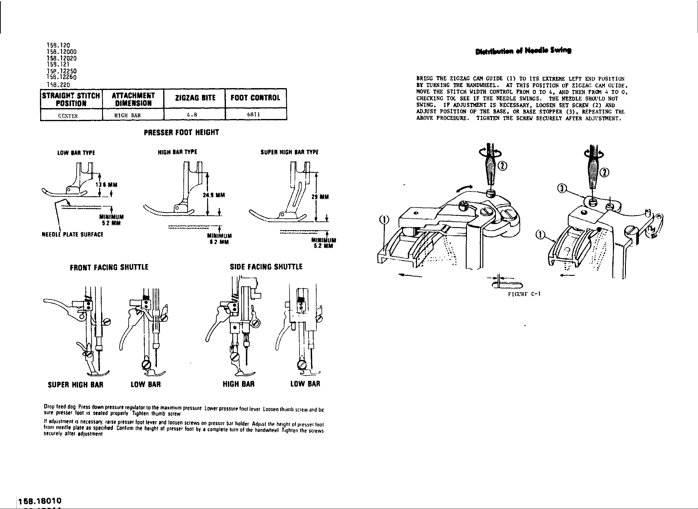
PRESSERFOOTHEIGHT
d Sw l
BKIf:G THE ZIGZAG CAN GUIDE (l) TO ITS r,XTRE/tE LEFT L_D POSITION
bY TURNING THE HAND'EEL* AT THIS POSITION OF ZIGZAC C_M GUIDE,
MOVE THE STITCH WIDTH CON._ROL FROH O TO 4, AND THEN FROH _ TO O,
CHECKING TO(. SEE IF THE NEEDLE SW][NGS. THE NEEDLE SHOULD NOT
SWING. IF ADJUSTHENT IS NECESSARY, LOOSEN SET SCREW (2) AND
ADJUST POSITION OF THE BASE, OR BASE STOPPER (3), REPEATING THE
ABOVE PROCEDURE. TIGHTEN THE SCREW SECUItELY AFTER ADJ_STHENT.
LOW|ARTYPE
..__._13 6 MM
MINIMUM
52 MM
NEEDLE PLATE SURFACE MINIMUM
HIGH BARTYPE
62 MM
FRONTFACINGSHUTTLE
SUPER HIGH lIAR TYPE (
MINIMUM
5.2 MM
SlOE FACINGSHU'i'rLE
FI €,_RF C-I
SUPERHIGH BAR LOW BAR HIGH BAR LOW BAR
Drop feed dog Pressdownpressureregulatortothe max;mum pressureLowerpressorPfootlever LoosenIhumb soew andbe
sure presser foot os seated properly Taghtenthumb screw
If adluslmenl asnecessary,raise presserloot lever and loosenscrewson pressor bar holder Adlustthe hefght of p_es_effoot
from needle plate as specdled Conformthe height of presser toot by a complete turn of the handwheel T_ghtenthe sc|ews
securelyafter adjustment
i158.18010
158.120
158.12000
158.12020
158.121
1 58.12250
158.12260
1 58.220
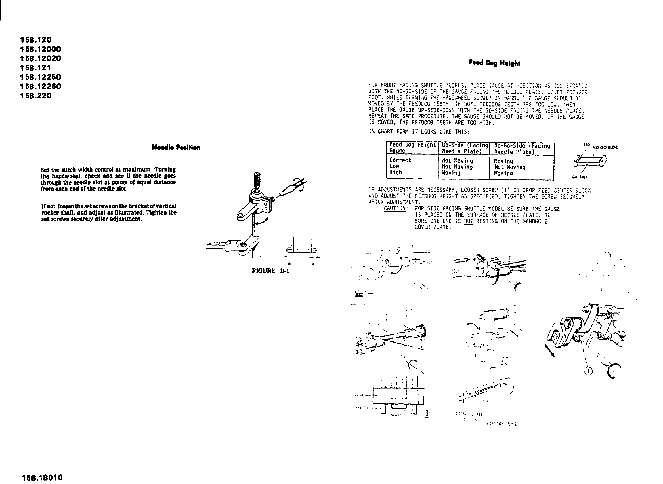
Feed 0cO Height
:OR FRO_ITFA,_,I:_GSHUTTLE '_g&ELS,-_LzC_;_US[ _T ;OS:TIOI__,S;LL.STR'.'ZC
._ITHTHE _IO-GO-SI_EOF THE SALSE F':,C:_S"_E ':Z=SL__L_TE. LO'.IER_R[_.._ZR
FOOT. WHILE TL'RNI:,GT_F 4A:|G'._HEELSLOWL¢ 3v _';D, ÷uE SALGE GHOUL] SE
'4OVE3BY THE FEEDCOG TEETH. ;F :40T, :EE_DOG TF.F'T_._RE "00 LO._._HE'_
PLACE THE GAUGE UP-SIDE-DOW_J'rITHT._ESO-SIDE FACI',GT#[ ',EEDLEPLATE.
REPEAT THE SM'IEPROCEDURE. THE GAUGE SHOULD ;.'OTBE '_OVED. I_ THE GAUGE
IS ,_IOVED,THE FEEDDOG TEETH ARE TOO HIGH.
IN CHART FORM IT LOOKS LIKE THIS:
NeedlePmdtle.
Set thestitch width control at maximum Turnlni
the handwheel,cheek and see If the nero goes
throuEh the needle slot at points of equal diltanee
from each end of the needle slot.
If not, loosen the set screws on the bracket of vertical
rocker shaft, and adjust as illustrated. T_hten the
set screws securely after adjustment.
FIGURE D-I
Feed Dog Height Go-Side (FacingI r|o-Go-Si_ (Facing l ,,oNo_ossos
COrrect Hot Moving I Moving _._-------_/
Low Hot Moving lHot Moving
Gauge Needle Plate} I Needle P_ate) i '"
High _ovlng J Moving
IF ADJUST)IE'ITSARE :IEOESSARY,LODGE';SCRE:(',ll0_IDROP ,€':'-.=-_'I'[_"_LD_Kr'
&:(DADJUST T#E FEEDDOG HEIGHT AS SPECIFIED. TIGHTE_ T_[ SCI[',.;S[;.JREL'_
AFTER ADJUS,_,<E'4T.
CAUTION: FOR SIDE FACI2;GSHUT'L[ _ODEL BE SURE T_E )AUGE
IS _LACED ON THE SJRFACE OF :|EEDLEPLATE. B_.
SURE ONE E'¢OIS 'lOTRESTING ON .'HEHANDHGLE
COVER PLATE.
I
• _ • o ,
158.18010
/
. _,_;-
I
\

NEEDLE TIMING TO SHUTTLE
NEEDLE BAR HEIGHT
THE RADIAL TIMING GAUGESAND TEST PINS, AS
ILLUSTIL_TED BELOW,ARE AVAILABLE FROMDIVISION
92, SOURCE192. THE KIT IS IDENTIFIED AS
#69659° EACHGAUGEAND TEST PIN CAN ALSO BE
ORDEREDINDIVIDUALLY.
THIS KIT IS USEDFOR SOURCE148 AND 15B
VERTICAL BOBBIN sEWING MACHINES.
Nudb Ck_mm m Shrine
The clelrmce *'1.'* *'b." "c." and the In_e "'d" are v_ry
¢¢ltlCal _omts *n (llaticm to _e n4Ndke tlm*r_ 1o shuttle.
HOW_. the_ 9_ntt a_e wsu&lly _t_moned _ usual tl_
Rado_W_mlng _lU!leS.
NOTE:
No _tme_t _ d4omd fo_ "_meemo_ _" for me
feat.lint mut_e md_s. Fo_Niultment foqJNk_le
modM$._eme rsforto Filwaee(_3.
RADIAL
TIMING GAUGE
#69894
RADIAL
TIMI[;GGAUGE
#69892
RADIAL
TIMING GAUGE
'69893
_"_ z. TEST PIN
w /7
FIGURE G-I eb9895
A #69313
RADIAL
TIMING GAUGE
(O2S - O..lSmm)
FIGURE G-2
168.18010

NEEDLETIMINGTOSHUTTLE
Nmldll¢ktm l ll mkl
The t0tl0Wml] Klfustmanl _s_dl_wd or,Iv for the SKJe.tKIhe
shuttle models
Ifltett nlqldlO and tighten the handle clamp s_r(_w tKuroly
8ring the n_ldtt t0 ,tS i0*lit potltt0fl by turnl_l the hind
v_41el ChKk Io _ ,f tl_O¢ttMM_Ca betw_ln IP,4n_KIIo and
the Ihuttle iS wdhm the koeclf_ld Itm,I If nOt. Io_en screw
12) On the muttll gu,dM _#kel tad adl_st the pCht,Oa of
shuttle by st,dOg zt etth_ toward the lift 0€ rill'el untd the
wol_r €lewance _s oDtolned, T_ten the zcrew 14cutely
after IdNstment,
CAUTION: 114_ th41 _ el4mady dote n_l rltlN
DIMENSIONB
FIGUREO.3
Figure G 3 gives e general zdee of the use of the radral
!truing gauge Fallacythe mstzucPOns _t the lell which
pertain to thts modelis}
_o I,N4-I.INt._
(t.! - I.l _)
PlOdR| G4

168.120
168.12000
158.12020
168.121
168.12250
158,12260
168.220
Zigzag Synchrenixati_n
Set stitch width control at maximum Turntn| the
handwl_eJ, checx and see if the needle side motion
on the standard plone (0.0,194'_ch above the upper
surface of the ntedJe pJase)at both needle posJUonl
,|
i" q
' 12
e OO_3e 030_'_'i
FIGUItE H-_ -
come within the enlOneerln| limit of 0.0131 inch. If
not. Ioo_n set so_w 42) on the worm gear either
dire_on. TIl_ten the screw ,2) securely after
ad.hlsunent.
.#
tj ;. I
\
Set ititcll lfld_ control lit O, Andhun UseJlald-
wheel tow_rda;you. ;t the need;e i,alnp ,t taJa
settln4, lo_en |¢r_ (1) I_d adjust thaipmPition
o( z_z_ stopper Ine/the: cUrecUontoms/nta/n
pet/eet strsqlht IutehJnlr. T_bten the |crew
securely after adJu4tment.
$_, S*,chinS
FIGURE 1.1
 Loading...