

Kenmore 153.552400, 153.552500 Use And Care Manual
O
Use & Care Guide
Model No.
153.552400 40 Gallon Tall
153.552500 50 Gallon Tall
Kenmore®
Gas Water Heater
For potable water heating only.
Not suitable for space heating.
Not for use in mobile homes.
LOW LEAD
NTENT
C
INSTALLER: Affix these instructions to or near
the water heater.
OWNER: Retain these instructions for future
reference.
FOR YOUR SAFETY: An odorant is added to
the gas used by this water heater.
ADVERTENCIA
Si no puede leer o entender el inglés y necesita el manual de
instrucciones en español, puede solicitarlo al 1-800-821-2017. NO
TRATE DE INSTALAR U OPERAR ESTE CALENTADOR DE AGUA
SI NO ENTIENDE LAS INSTRUCCIONES. No hacer caso de esta
advertencia podría originar lesiones graves o mortales.
P/N 100264212 (0315)
Sears Brands Management Corporation,
Hoffman Estates, IL 60179 U.S.A.
www.kenmore.com
1
SAFE INSTALLATION, USE AND SERVICE
Your safety and the safety of others is extremely important in the installation, use and servicing of this water heater.
Many safety-related messages and instructions have been provided in this manual and on your own water heater to warn you and others of
a potential injury hazard. Read and obey all safety messages and instructions throughout this manual. It is very important that the meaning
of each safety message is understood by you and others who install, use or service this water heater.
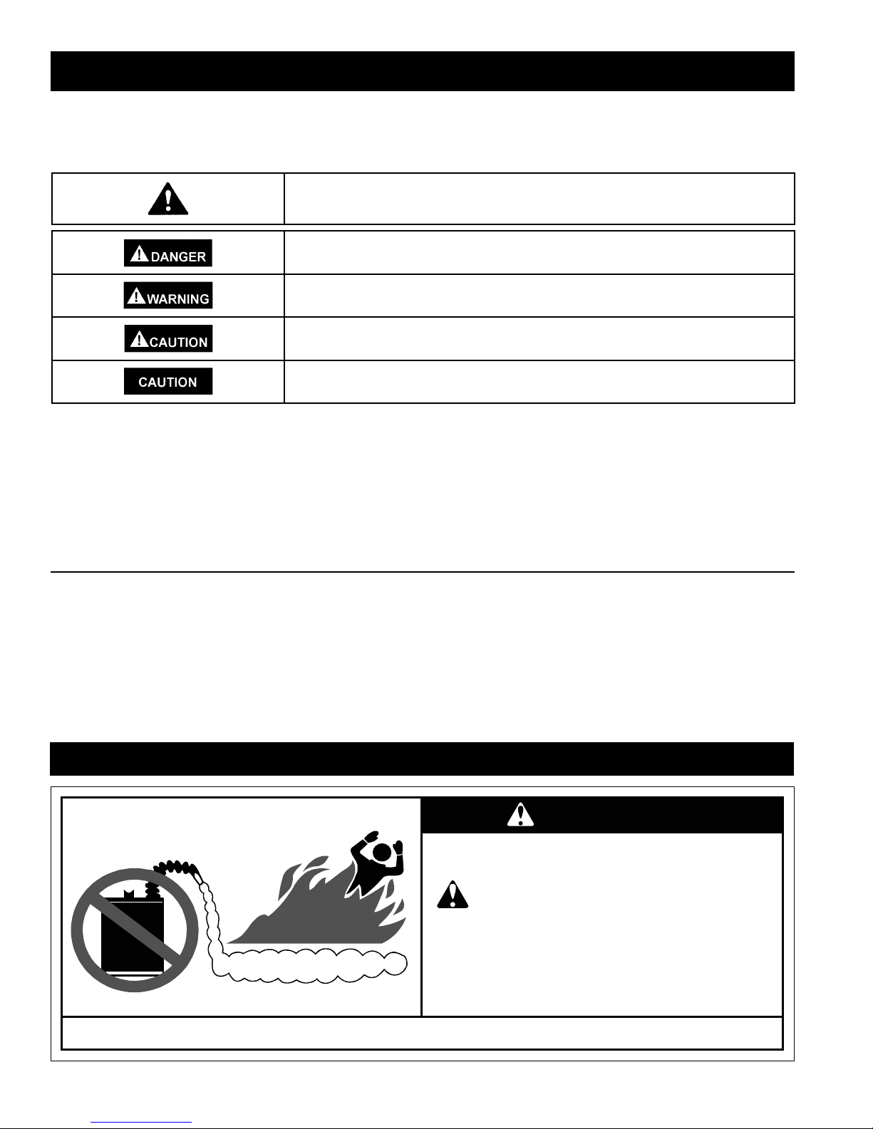
This is the safety alert symbol. It is used to alert you to potential personal injury hazards.
Obey all safety messages that follow this symbol to avoid possible injury or death.
DANGER indicates an imminently hazardous situation which, if not avoided, will result
in death or injury.
WARNING indicates a potentially hazardous situation which, if not avoided, could result
in death or injury.
CAUTION indicates a potentially hazardous situation which, if not avoided, could result
in minor or moderate injury.
CAUTION used without the safety alert symbol indicates a potentially hazardous
situation which, if not avoided, could result in property damage.
All safety messages will generally tell you about the type of hazard, what can happen if you do not follow the safety message and
how to avoid the risk of injury.
The California Safe Drinking Water and Toxic Enforcement Act requires the Governor of California to publish a list of substances known to
the State of California to cause cancer, birth defects, or other reproductive harm, and requires businesses to warn of potential exposure to
such substances.
• WARNING: This product contains a chemical known to the State of California to cause cancer, birth defects, or other reproductive harm.
• This appliance can cause low-level exposure to some of the substances included in the act.
This product is certified to comply with a maximum weighted average of 0.25% lead content as required in some areas.
IMPORTANT DEFINITIONS
• Qualified Technician: A qualified technician must have ability equivalent to a licensed tradesman in the fields of plumbing, air supply,
venting, and gas supply, including a thorough understanding of the requirements of the National Fuel Gas Code as it relates to the
installation of gas fired water heaters. The qualified technician must also be familiar with the design features and use of flammable vapor
ignition resistant water heaters, and have a thorough understanding of this instruction manual.
• Service Agency: A service agency also must have ability equivalent to a licensed tradesman in the fields of plumbing, air supply, venting
and gas supply, including a thorough understanding of the requirements of the National Fuel Gas Code as it relates to the installation of
gas fired water heaters. The service agency must also have a thorough understanding of this instruction manual, and be able to perform
repairs strictly in accordance with the service guidelines provided by the manufacturer.
• Gas Supplier: The natural gas or propane utility or service who supplies gas for utilization by the gas burning appliances within this
application. The gas supplier typically has responsibility for the inspection and code approval of gas piping up to and including the natural
gas meter or propane storage tank of a building. Many gas suppliers also offer service and inspection of appliances within the building.
SAFETY PRECAUTIONS
WARNING
FIRE AND EXPLOSION HAZARD
Can result in serious injury or death
Do not store or use gasoline or other
flammable vapors and liquids in the vicinity of this
or any other appliance. Storage of or use of
FLAMMABLES
Flammable Vapors
gasoline or other flammable vapors or liquids in the
vicinity of this or any other appliance can result in
serious injury or death.
Read and follow water heater warnings and instructions.
© Sears Brands Management Corporation
2
3

TABLE OF CONTENTS
SAFE INSTALLATION, USE AND SERVICE ...................................................................................................................... 2
SAFETY PRECAUTIONS ........................................................................................................................... 2-3
TABLE OF CONTENTS ................................................................................................................................. 4
LIMITED WARRANTY ................................................................................................................................................................ 5
CUSTOMER RESPONSIBILITIES ......................................................................................................................................... 6
PRODUCT SPECIFICATIONS ................................................................................................................................................ 6
MATERIALS AND BASIC TOOLS NEEDED ....................................................................................................................... 7
Materials Needed .....................................................................................................................................................7
Basic Tools................................................................................................................................................................7
TYPICAL INSTALLATION.......................................................................................................................................................... 8
INSTALLATION INSTRUCTIONS ..................................................................................................................................... 9-18
Removing the Old Water Heater ...............................................................................................................................9
Facts to Consider About the Location ................................................................................................................ 10-11
Insulation Blankets ............................................................................................................................................11-12
Combustion Air and Ventilation Appliances in Unconfined Spaces ........................................................................12
Combustion Air and Ventilation Appliances in Confined Spaces .......................................................................12-13
Water Piping ......................................................................................................................................................13-14
Temperature Pressure Relief Valve ...................................................................................................................15,16
Filling the Water Heater ..........................................................................................................................................16
Venting ...............................................................................................................................................................16-17
Gas Piping .........................................................................................................................................................17,18
Sediment Trap ........................................................................................................................................................18
OPERATING INSTRUCTIONS ........................................................................................................................................ 19-22
Lighting Instructions ................................................................................................................................................19
Lighting & Operating Label .....................................................................................................................................20
Temperature Regulation .........................................................................................................................................21
Operating the Temperature Control System ...........................................................................................................22
SERVICE AND ADJUSTMENT .............................................................................................................. 23-28
Venting System Inspection .....................................................................................................................................23
Burner Inspection ...................................................................................................................................................23
Removing the Burner Door Assembly ....................................................................................................................24
Ultra Low NOx Natural Gas Burner ........................................................................................................................24
Replacing the Pilot/Thermopile Assembly .........................................................................................................24-25
External Inspection & Cleaning of the Flame Trap .................................................................................................25
Cleaning the Combustion Chamber and Flame Trap .............................................................................................25
Replacing the Burner Door Assembly .....................................................................................................................26
Piezoelectric Igniter System ...................................................................................................................................26
Testing the Igniter System ......................................................................................................................................26
Removing and Replacing the Gas Control Valve/Thermostat ................................................................................27
Housekeeping .........................................................................................................................................................27
Anode Rod Inspection .......................................................................................................................................27-28
Temperature-Pressure Relief Valve Operation .......................................................................................................28
Draining ..................................................................................................................................................................28
Service ....................................................................................................................................................................28
TROUBLESHOOTING GUIDE ............................................................................................................... 29-35
Start Up Conditions ................................................................................................................................................29
Thermal Expansion ...........................................................................................................................................29
Strange Sounds ................................................................................................................................................29
Draft Hood Operation ........................................................................................................................................29
Condensation ....................................................................................................................................................30
Smoke/Odor ......................................................................................................................................................30
Operational Conditions ......................................................................................................................................30-31
Smelly Odor ......................................................................................................................................................30
Water Temperature Stacking .............................................................................................................................30
Air in Hot Water Faucets ...................................................................................................................................30
Safety Shut-Off .............................................................................................................................................30-31
Troubleshooting Items .......................................................................................................................................32-35
PARTS ORDER LIST ................................................................................................................................................................36
4

PRODUCT WARRANTY
KENMORE LIMITED WARRANTY
WITH PROOF OF SALE, the following warranty coverage applies
when this water heater is correctly connected, installed, operated and
maintained according to all supplied instructions. In all cases, replacement units, tanks or parts are warranted only for the unexpired portion
of the warranty period from the original date of sale.
FOR ONE YEAR from the date of sale this water heater is warranted
against defects in material or workmanship. A defective water heater
will receive free repair or replacement at option of seller.
FOR TWELVE YEARS from the date of sale this water heater is warranted against leaks in the tank. If a tank leak occurs within the fi rst
year, a new water heater of equal capacity and quality will be supplied
and installed at no charge. If a tank leak occurs after the fi rst year, a
new water heater of equal capacity and quality will be supplied but not
installed at no charge. You are responsible for the labor cost of water
heater installation after the fi rst year from the date of sale.
FOR TWELVE YEARS from the date of sale all water heater parts
are warranted against defects in material or workmanship. If a part is
defective within the fi rst year, a new part will be supplied and installed
at no charge. If a part is defective after the fi rst year, a new part will
be supplied but not installed at no charge. You are responsible for the
labor cost of part installation after the fi rst year from the date of sale.
For warranty coverage details to obtain free repair or replacement,
visit the web page: www.kenmore.com/warranty
This warranty applies for only two years on the tank and one year on
all parts if this water heater is ever used in a residence of more than
one family or in a commercial, institutional or industrial installation.
This warranty covers ONLY defects in material and workmanship,
and will NOT pay for:
1. Expendable items that can wear out from normal use, including but
not limited to fi lters, belts, bags or screw-in base light bulbs.
2. A service technician to clean or maintain this appliance, or to instruct
the user in correct appliance installation, operation and maintenance.
3. Service calls to correct appliance installation not performed by Sears
authorized service agents, or to repair problems with house fuses,
circuit breakers, house wiring, and plumbing or gas supply systems
resulting from such installation.
4. Damage to or failure of this appliance resulting from installation not
performed by Sears authorized service agents, including installation
that was not in accord with electrical, gas or plumbing codes.
5. Damage to or failure of this appliance, including discoloration or
surface rust, if it is not correctly operated and maintained according
to all supplied instructions.
6. Damage to or failure of this appliance, including discoloration or
surface rust, resulting from accident, alteration, abuse, misuse or
use for other than its intended purpose.
7. Damage to or failure of this appliance, including discoloration or
surface rust, caused by the use of detergents, cleaners, chemicals
or utensils other than those recommended in all instructions supplied
with the product.
8. Damage to or failure of parts or systems resulting from unauthorized
modifi cations made to this appliance.
9. Service to an
altered, or cannot easily be determined to have the appropriate
certifi cation logo.
appliance if the model and serial plate is missing,
Disclaimer of implied warranties; limitation of remedies
Customer’s sole and exclusive remedy under this limited warranty
shall be product repair or replacement as provided herein. Implied
warranties, including warranties of merchantability or fi tness for a
particular purpose, are limited to one year on the water heater, and
twelve years on the tank and parts, or the shortest period allowed by
law. Seller shall not be liable for incidental or consequential damages.
Some states do not allow the exclusion or limitation of incidental or
consequential damages, or limitation on the duration of implied warranties of merchantability or fi tness, so these exclusions or limitations
may not apply to you.
This warranty applies only while this appliance is used in the United States.
This warranty gives you specifi c legal rights, and you may also have
other rights which vary from state to state.
Sears Brands Management Corporation,
Hoffman Estates, IL 60179
Master Protection Agreements
Congratulations on making a smart purchase. Your new Kenmore®
product is designed and manufactured for years of dependable
operation. But like all products, it may require preventive maintenance
or repair from time to time. That’s when having a Master Protection
Agreement can save you money and aggravation.
The Master Protection Agreement also helps extend the life of your
new product. Here’s what the Agreement* includes:
• Parts and labor not just for repairing defects, but to help keep
products operating properly under normal use. Our coverage goes
well beyond the product warranty. No deductibles, no functional
failure excluded from coverage— real protection.
• Expert service by a force of more than 10,000 authorized Sears
service technicians, which means someone you can trust will be
working on your product.
• Unlimited service calls and nationwide service, as often as you want
us, whenever you want us.
• “No-lemon” guarantee – replacement of your covered product if four
or more product failures occur within twelve months.
• Product replacement if your covered product can’t be fi xed.
• Annual Preventive Maintenance Check at your request – no extra
charge.
• Fast help by phone – we call it Rapid Resolution – phone sup-port
from a Sears representative on all products. Think of us as a “talking owner’s manual.”
• Power surge protection against electrical damage due to power
fl uctuations.
• $250
• Rental reimbursement if repair of your covered product takes longer
• 25% discount off the regular price of any non-covered repair service
Once you purchase the Agreement, a simple phone call is all that it
takes for you to schedule service. You can call anytime day or night, or
schedule a service appointment online.
The Master Protection Agreement is a risk free purchase. If you cancel
for any reason during the product warranty period, we will provide a
full refund. Or, a prorated refund anytime after the product warranty
period expires. Purchase your Master Protection Agreement today!
Some limitations and exclusions apply. For prices and additional
information in the U.S.A. call 1-800-827-6655.
* Coverage in Canada varies on some items. For full details call
Sears Canada at 1-800-361-6665.
Food Loss Protection annually for any food spoilage that is the
result of mechanical failure of any covered refrigerator or freezer.
than promised.
and related installed parts.
Sears Installation Service
For Sears professional installation of home appliances, garage door
openers, water heaters, and other major home items, in the U.S.A. or
Canada call 1-844-553-6667.
5

CUSTOMER RESPONSIBILITIES
Thank You for purchasing a Kenmore water heater. Properly
installed and maintained, it should give you years of trouble free
service. If you should decide that you want the new water heater
professionally installed by Sears, call 1-844-553-6667. They
will arrange for prompt, quality installation by Sears authorized
contractors.
Abbreviations Found In This Instruction Manual:
• CSA - Canadian Standards Association
• ANSI - American National Standards Institute
• NFPA - National Fire Protection Association
• ASME - American Society of Mechanical Engineers
• This gas-fired water heater is design certified by CSA
INTERNATIONAL under American National Standard/CSA
Standard for Gas Water Heaters ANSI Z21.10.1 • CSA 4.1
(current edition).
• Read the “Safety Precautions” section first (pages 2 and 3 of
this manual) and then read the entire manual carefully. If you
don’t follow the safety rules, the water heater will not operate
properly. It could cause DEATH, SERIOUS BODILY INJURY
AND/OR PROPERTY DAMAGE.
This manual contains instructions for the installation, operation,
and maintenance of the gas-fired water heater. It also contains
warnings through out the manual that you must read and be
aware of. All warnings and all instructions are essential to the
proper operation of the water heater and your safety. Since
we cannot put everything on the first few pages, READ THE
ENTIRE MANUAL BEFORE ATTEMPTING TO INSTALL OR
OPERATE THE WATER HEATER.
• The installation must conform with these instructions and
the local code authority having jurisdiction. In the absence
of local codes, installations shall comply with the current
edition of The National Fuel Gas Code ANSI Z223.1/NFPA
54. This publication is available from the Canadian Standards
Association, 8501 East Pleasant Valley Rd, Cleveland
Ohio 44131, or The National Fire Protection Association, 1
Batterymarch Park, Quincy, MA 02269.
• If after reading this manual you have any questions or do
not understand any portion of the instructions, call the Sears
Service Center.
• Carefully plan the place where you are going to put the
water heater. Correct combustion, vent action, and vent
pipe installation are very important in preventing death
from possible carbon monoxide poisoning and fires. See
figure 1.
Examine the location to ensure the water heater complies
with the Facts to Consider About the Location section in this
manual.
• For California installation this water heater must be braced,
anchored, or strapped to avoid falling or moving during
an earthquake. See instructions for correct installation
procedures. Instructions may be obtained from the California
Office of the State Architect, 1102 Q Street, Suite 5100,
Sacramento, CA 95811. Instructions can also be downloaded
to your computer at WWW.dsa.dgs.ca.gov.
• Complies with 10 ng/J SCAQMD rule #1121 and districts
having equivalent NOx requirements.
MODEL NUMBER
153.552400
153.552500
TANK
CAPACITY IN
GALS (LTRS)
40 (151)
50 (189)
PRODUCT SPECIFICATIONS
RECOVERY
TYPE OF
GAS
NATURAL
NATURAL
INPUT
RATE
(Btu/hr)
40,000
40,000
RATE GALS.
PER HOUR @
90°F RISE
41
41
3” (76) OR 4” (102)
3” (76) OR 4” (102)
MINIMUM
VENT PIPE
INCHES
(mm)
DIAMETER
INCHES
(mm)
17-3/4 (451)
19-3/4 (502)
DIMENSIONS IN
INCHES (mm)
HEIGHT TO
JACKET TOP
58-1/2 (1486)
57-1/2 (1461)
6
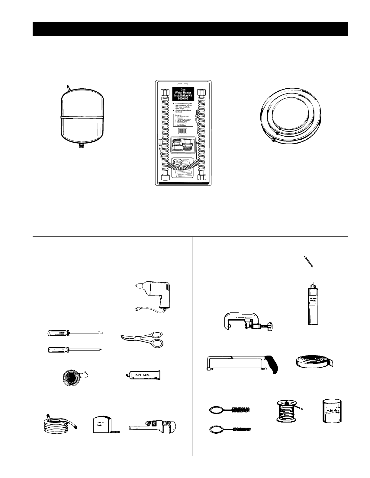
MATERIALS AND BASIC TOOLS NEEDED
MATERIALS NEEDED
To simplify the installation Sears has available the installation parts shown below. You may or may not need all of these materials,
depending on your type of installation.
EXPANSION TANKS FOR
THERMAL EXPANSION
CONDITIONS AVAILABLE
IN 2 GALLONS
(7.6 LITERS) AND
5 GALLONS (18.9 LITERS)
CAPACITY THROUGH
LOCAL SEARS STORE
OR SERVICE CENTER.
WATER HEATER INSTALLATION KIT
WITH FLEXIBLE CONNECTORS FOR 3/4”
(19.05 mm) COPPER PLUMBING AND FLEXIBLE
GAS CONNECTOR WITH FITTINGS.
BASIC TOOLS
You may or may not need all these tools, depending on your
type of installation. These tools can be purchased at your local
Sears Store.
• Pipe Wrenches (2) 14” (356 mm)
• Screwdriver
• Tin Snips
• 6’ (1.82 m) Tape or Folding Ruler
• Garden Hose
• Drill
• Pipe Dope or Teflon Tape
SLOT-HEAD SCREWDRIVER
DRILL
METAL DRAIN PANS
AVAILABLE IN 20” (508
mm) DIAMETER FOR
WATER HEATERS HAVING A
DIAMETER 18” (457 mm) OR
LESS, 24” (610mm) DIAMETER
FOR WATER HEATERS HAVING
A DIAMETER 22” (559 mm)
OR LESS AND AVAILABLE IN
28” (711 mm) DIAMETER FOR
WATER HEATERS HAVING A
DIAMETER 26” (660 mm) OR
LESS.
ADDITIONAL TOOLS NEEDED
WHEN SWEAT SOLDERING
• Tubing Cutters or Hacksaw
• Propane Torch
• Soft Solder
• Solder Flux
• Emery Cloth
• Wire Brushes
TUBING CUTTER
PROPANE
TORCH
PHILLIPS SCREWDRIVER
ROLL OF TEFLON
TAPE (USE ONLY ON
WATER CONNECTIONS)
GARDEN HOSE
6 FOOT TAPE
USE FOR WATER AND GAS
TIN SNIPS
PIPE DOPE
(SQUEEZE TUBE)
CONNECTIONS
PIPE WRENCH
3/4” (19 mm) WIRE BRUSH
1/2” (13 mm) WIRE BRUSH
7
HACKSAW
ROLL OF
EMERY CLOTH
ROLL OF LEAD-FREE
SOFT SOLDER
SOLDER
FLUX
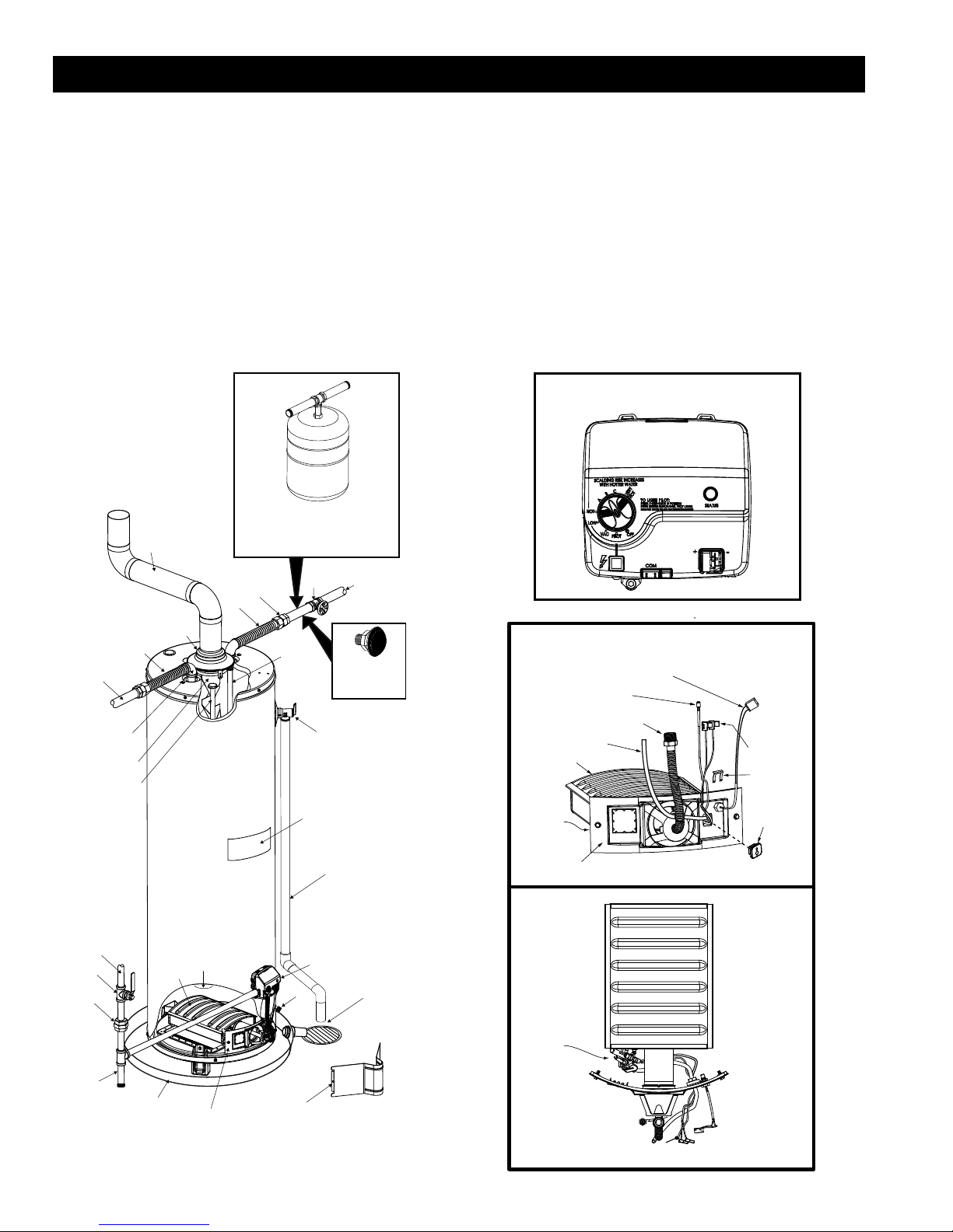
TYPICAL INSTALLATION
GET TO KNOW YOUR WATER HEATER - GAS MODELS
A Vent Pipe
B Draft Hood
C Anode
D Hot Water Outlet
E Outlet
F Flexible Water Connections
G Gas Supply
H Manual Gas Shut-off Valve
I Ground Joint Union
* INSTALL IN ACCORDANCE
WITH LOCAL CODES.
* SEDIMENT TRAP AS
REQUIRED BY LOCAL
CODES.
TO VENT
TERMINATION ON
ROOF
A
INSTALL THERMAL EXPANSION
TANK IF WATER HEATER IS
INSTALLED IN A CLOSED
M
F
J Sediment Trap
K Inner Door
L Outer Door
M Union
N Inlet Water Shut-off Valve
O Cold Water Inlet
P Inlet Dip Tube
Q Temperature-Pressure Relief Valve
R Rating Plate
WATER SYSTEM
N
O
S Flue Baffl e
T Gas Control Valve/Thermostat
U Drain Valve
V Pilot and Burner Door Assemblies
W Flue
X Metal Drain Pan
(T) GAS CONTROL VALVE/
THERMOSTAT
VAC
B
F
D
E
S
C
G
H
I
J
X
W
V
K
* ALL PIPING MATERIALS TO BE
SUPPLIED BY CUSTOMERS.
P
R
T
U
L
VACUUM RELIEF
VALV E
*INSTALL PER
LOCAL CODES
Q
DISCHARGE PIPE
(Do not cap or plug)
6” MAXIMUM
AIR GAP
FIGURE 1.
(V) PILOT AND BUNER DOOR
ASSEMBLIES
SENSOR WIRES
IGNITER
WIRE
MANIFOLD TUBE
PILOT TUBE
MAIN BURNER
PILOT
ASSEMBLY
(SEE BELOW)
BURNER DOOR
PILOT
ASSEMBLY
FRONT VIEW
TOP VIEW
THERMOPILE
CONNECTORS
RETAINER
CLIP
MANIFOLD
COMPONENT
BLOCK
8
INSTALLATION INSTRUCTIONS
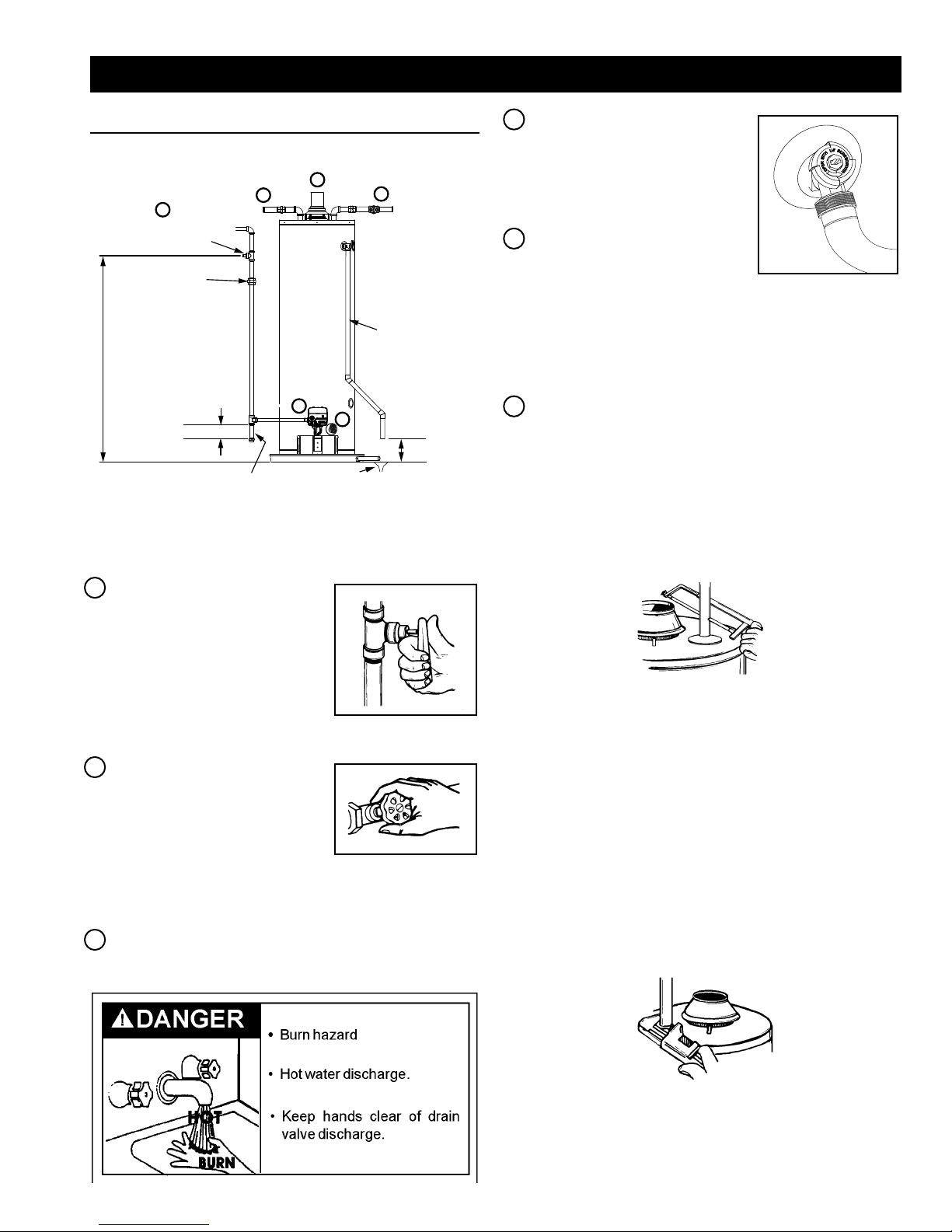
Removing the Old Water Heater
1
MANUAL GAS
SHUT-OFF VALVE
GROUND
JOINT
UNION
CHECK WITH
LOCAL UTILITY
FOR MINIMUM HEIGHT
3” MINIMUM
SEDIMENT TRAP
6
5
3
SUITABLE
DRAIN
FIGURE 2.
2
DISCHARGE PIPE
4
(DO NOT CAP
OR PLUG)
6” MAXIMUM
AIR GAP
4. Attach a hose to the water heater
drain valve and put the other end
in a floor drain or outdoors. (See
Figures 2 and 5.) Open the water
heater drain valve.
5. Disconnect the vent pipe from
the draft hood where it connects
to the water heater. In most
installations the vent pipe can be
lifted off after any screw or other
FIGURE 5.
attached devices are removed. Dispose of the draft hood.
The new water heater has a draft hood which must be used
for proper operation.
6. If you have copper piping to the water heater, the two copper
water pipes can be cut with a hacksaw approximately four
inches away from where they connect to the water heater.
See Figure 6. This will avoid cutting off pipes too short.
Additional cuts can be made later if necessary. Disconnect the
temperature-pressure relief valve drain line. When the water
heater is drained, disconnect the hose from the drain valve.
Close the drain valve. The water heater is now completely
disconnected and ready to be removed.
1. Turn “OFF” the gas supply to
the water heater.
If the main gas line shutoff valve
serving all gas appliances is used,
also shut “OFF” the gas at each
appliance. Leave all gas appliances
shut “OFF” until the water heater
installation is completed. See
Figures 2 and 3.
FIGURE 3.
2. Open a nearby hot water faucet
until the water is no longer hot.
When the water has cooled,
turn “OFF” the water supply to
the water heater at the water
shut off valve or water meter.
Some installations require
that the water be turned off to
FIGURE 4.
the entire house. See Figures 2
and 4.
3. Check again to make sure the gas supply is “OFF” to the water
heater. Then disconnect the gas supply connection from the
gas control valve.
FIGURE 6.
If you have galvanized pipes to the water heater, loosen
the two galvanized pipes with a pipe wrench at the union in
each line. Also disconnect the piping remaining to the water
heater. See Figure 7. These pieces should be saved since
they may be needed when reconnecting the new water heater.
Disconnect the temperature-pressure relief valve drain line.
When the water heater is drained, disconnect the hose from
the drain valve. Close the drain valve. The water heater
is now completely disconnected and ready to be removed.
Mineral buildup or sediment may have accumulated in the
old water heater. This causes the water heater to be much
heavier than normal and this residue, if spilled out, could
cause staining.
FIGURE 7.
9
Facts to Consider About
the Location
Carefully choose an indoor location for the new water heater.
The placement is a very important consideration for the safety
of the occupants in the building and for the most economical
use of the appliance. This water heater is not for use in
manufactured (mobile) homes or outdoor installation.
Whether replacing an old water heater or putting the water heater
in a new location, the following critical points must be observed:
• Select a location indoors as close as practical to the gas
vent or chimney to which the water heater vent is going to be
connected, and as centralized with the water piping system
as possible.
• Selected location must provide adequate clearances for
servicing and proper operation of the water heater.
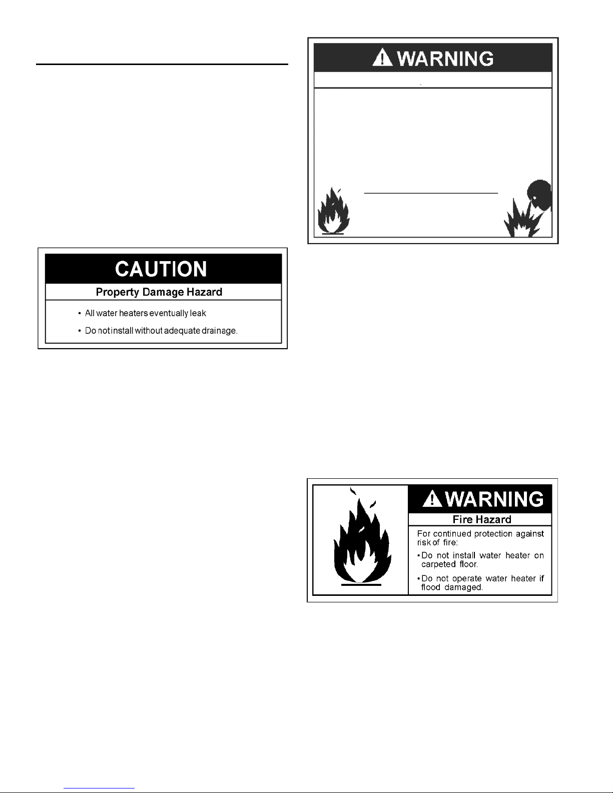
Installation of the water heater must be accomplished in such a
manner that if the tank or any connections should leak, the flow
will not cause damage to the structure. For this reason, it is not
advisable to install the water heater in an attic or upper floor. When
such locations cannot be avoided, a suitable metal drain pan should
be installed under the water heater. Metal drain pans are available
at your local Sears or hardware store. Such a drain pan must have
a minimum length and width of at least 2 inches (51 mm) greater
than the water heater dimensions and must be piped to an adequate
drain. The pan must not restrict combustion air flow.
Water heater life depends upon water quality, water pressure
and the environment in which the water heater is installed. Water
heaters are sometimes installed in locations where leakage may
result in property damage, even with the use of a metal drain
pan piped to a drain. Unanticipated damage can be reduced
or prevented by a leak detector or water shut-off device used
in conjunction with a piped metal drain pan. These devices are
available from some plumbing supply wholesalers and retailers,
and detect and react to leakage in various ways:
Fire or Explosion Hazard
'RQRWVWRUHRUXVHJDVROLQHRURWKHUIODPPDEOHYDSRUV
DQGOLTXLGVLQWKHYLFLQLW\RIWKLVRUDQ\RWKHUDSSOLDQFH
$YRLGDOOLJQLWLRQVRXUFHVLI\RXVPHOO/3JDV
'RQRWH[SRVHZDWHUKHDWHUFRQWUROWRH[FHVVLYHJDV
SUHVVXUH
8VHRQO\JDVVKRZQRQUDWLQJSODWH
0DLQWDLQUHTXLUHGFOHDUDQFHVWRFRPEXVWLEOHV
NHHSLJQLWLRQVRXUFHVDZD\IURPIDXFHWVDIWHUH[WHQGHG
SHULRGRIQRQXVH
5HDGLQVWUXFWLRQPDQXDOEHIRUH
LQVWDOOLQJXVLQJRUVHUYLFLQJ
ZDWHUKHDWHU
INSTALLATIONS IN AREAS WHERE FLAMMABLE LIQUIDS
(VAPORS) ARE LIKELY TO BE PRESENT OR STORED
(GARAGES, STORAGE AND UTILITY AREAS, ETC.): Flammable
liquids (such as gasoline, solvents, propane [LP or butane, etc.]
and other substances such as adhesives, etc.) emit flammable
vapors which can be ignited by a gas water heater’s pilot light or
main burner. The resulting flashback and fire can cause death
or serious burns to anyone in the area. Even though this water
heater is a flammable vapor ignition resistant water heater and
is designed to reduce the chances of flammable vapors being
ignited, gasoline and other flammable substances should never
be stored or used in the same vicinity or area containing a gas
water heater or other open flame or spark producing appliance.
Keep combustibles such as boxes, magazines, clothes, etc., away
from the water heater area.
Also, the water heater must be located and/or protected so it is
not subject to physical damage by a moving vehicle.
• Sensors mounted in the metal drain pan that trigger an alarm
or turn off the incoming water to the water heater when leakage
is detected.
• Sensors mounted in the metal drain pan that turn off the water
supply to the entire home when water is detected in the metal
drain pan.
• Water supply shut-off devices that activate based on the water
pressure differential between the cold water and hot water
pipes connected to the water heater.
• Devices that will turn off the gas supply to a gas water heater
while at the same time shutting off its water supply.
This water heater must not be installed directly on carpeting.
Carpeting must be protected by metal or wood panel beneath
the appliance extending beyond the full width and depth of the
appliance by at least 3 inches (76.2mm) in any direction, or if
the appliance is installed in an alcove or closet, the entire floor
must be covered by the panel. Failure to heed this warning may
result in a fire hazard.
10
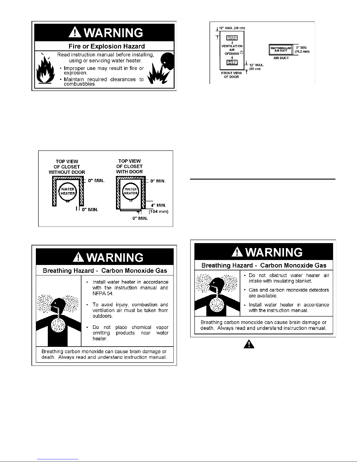
Minimum clearances between the water heater and combustible
surfaces are 0 inch at the sides and rear, 4 inches (102 mm)
at the front, and 6 inches (153 mm) from the vent pipe. See
Figure 8. Clearance from the top of the jacket is 8 inches (203
mm) on most models. Note that a lesser dimension may be
allowed on some models. Refer to the label attached adjacent
to the gas control valve on the water heater.
FIGURE 8.
FIGURE 9.
If this water heater will be used in beauty shops, barber shops,
cleaning establishments, or self-service laundries with dry
cleaning equipment, it is imperative that the water heater or
water heaters be installed so that combustion and ventilation
air be taken directly from outdoors (direct vent).
Propellants of aerosol sprays and volatile compounds, (cleaners,
chlorine based chemicals, refrigerants, etc.) in addition to being
highly flammable in many cases, will also change to corrosive
hydrochloric acid when exposed to the combustion products of
the water heater. The results can be hazardous, and also cause
product failure.
Insulation Blankets
Insulation blankets available to the general public for external
use on gas water heaters are not necessary with Kenmore
products. The purpose of an insulation blanket is to reduce the
standby heat loss encountered with storage tank heaters. Your
Kenmore water heater meets or exceeds the National Appliance
Energy Conservation Act standards with respect to insulation
and standby loss requirements, making an insulation blanket
unnecessary.
A gas water heater cannot operate properly without the correct
amount of air for combustion. See Figure 9. Do not install in a
confined area such as a closet, unless you provide air as shown
in the Locating The New Water Heater section. Never obstruct
the flow of ventilation air. If you have any doubts or questions at
all, call your gas supplier. Failure to provide the proper amount of
combustion air can result in a fire or explosion and cause death,
serious bodily injury, or property damage.
WARNING
Should you choose to apply an insulation blanket to this
heater, you should follow these instructions (See Figure 1 for
identification of components mentioned below). Failure to follow
these instructions can restrict the air flow required for proper
combustion, potentially resulting in fire, asphyxiation, serious
personal injury or death.
• Do not apply insulation to the top of the water heater, as this
will interfere with safe operation of the draft hood.
• Do not cover the outer door, thermostat or temperature &
pressure relief valve.
• Do not allow insulation to come within 2” (50.8 mm) of the
floor to prevent blockage of combustion air flow to the burner.
• Do not cover the instruction manual. Keep it on the side of
the water heater or nearby for future reference.
11
• Do obtain new warning and instruction labels from Sears for
placement on the blanket directly over the existing labels.
• Do inspect the insulation blanket frequently to make certain
it does not sag, thereby obstructing combustion air flow.
Combustion Air and Ventilation for
Appliances Located in Unconfined Spaces
The confined space shall be provided with two permanent
openings, one commencing within 12 inches (30 cm) of the top
and one commencing within 12 inches (30 cm) from the bottom
of the enclosure. The openings shall communicate directly, or
by ducts, with the outdoors or spaces (crawl or attic) that freely
communicate with the outdoors.
UNCONFINED SPACE is space whose volume is not less than
50 cubic feet per 1,000 Btu per hour (4.8 m
aggregate input rating of all appliances installed in that space.
Rooms communicating directly with the space in which the
appliances are installed, through openings not furnished with
doors, are considered a part of the unconfined space.
In unconfined spaces in buildings, infiltration may be adequate
to provide air for combustion, ventilation and dilution of flue
gases. However, in buildings of tight construction (for example,
weather stripping, heavily insulated, caulked, vapor barrier,
etc.), additional air may need to be provided using the methods
described in Combustion Air and Ventilation for Appliances
Located in Confined Spaces.
3
per kW) of the
Combustion Air and Ventilation for
Appliances Located in Confined Spaces
CONFINED SPACE is a space whose volume is less than
50 cubic feet per 1,000 Btu per hour (4.8 m3 per kW) of the
aggregate input rating of all appliances installed in that space.
A. ALL AIR FROM INSIDE BUILDINGS:
(See Figure 9 on page 11 and Figure 10 below)
The confined space shall be provided with two permanent
openings communicating directly with an additional room(s) of
sufficient volume so that the combined volume of all spaces
meets the criteria for an unconfined space. The total input of all
gas utilization equipment installed in the combined space shall
be considered in making this determination. Each opening shall
have a minimum free area of one square inch per 1,000 Btu per
hour (22 cm2/kW) of the total input rating of all gas utilization
equipment in the confined space, but not less than 100 square
inches (645 cm2). One opening shall commence within 12 inches
(30 cm) of the top and one commencing within 12 inches (30
cm) of the bottom of the enclosures.
FIGURE 11.
• When directly communicating with the outdoors, each opening
shall have a minimum free area of 1 square inch per 4,000
Btu per hour (5.5 cm2/kW) of total input rating of all equipment
in the enclosure. See Figure 11.
• When communicating with the outdoors through vertical
ducts, each opening shall have a minimum free area of
1 square inch per 4,000 BTU per hour (5.5 cm2/kW) of
total input rating of all equipment in the enclosure. See
Figure 12.
FIGURE 10.
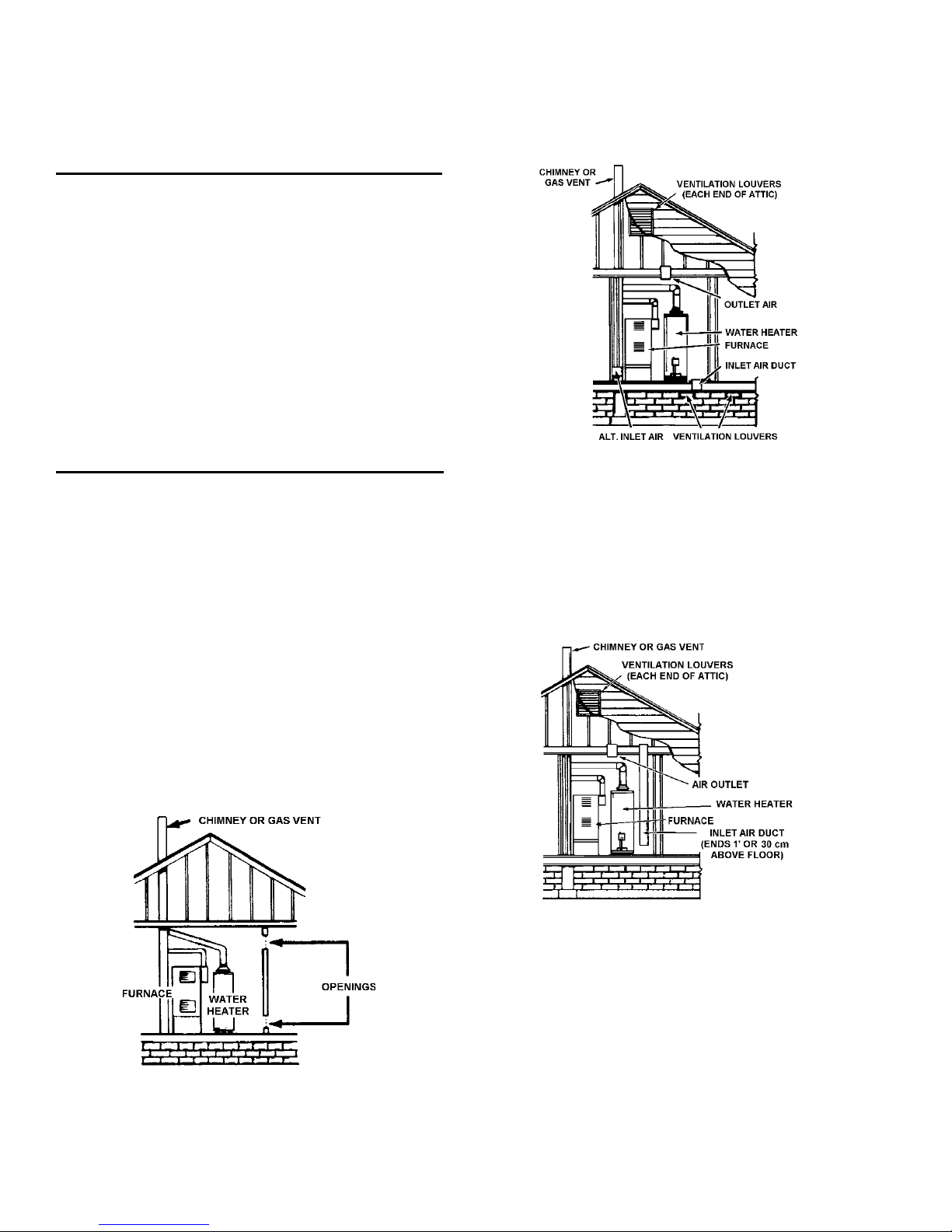
B. ALL AIR FROM OUTDOORS: (See Figures 9, 11,12,13 and 13A)
FIGURE 12.
• When communicating with the outdoors through horizontal
ducts, each opening shall have a minimum free area of
1 square inch per 2,000 BTU per hour (11 cm
total input rating of all equipment in the enclosure. See
Figure 13.
• When ducts are used, they shall be of the same crosssectional area as the free area of the openings to which
they connect. The minimum short side dimension of
rectangular air ducts shall not be less than 3 inches
(7.6 cm). See Figure 13.
12
2
/kW) of
 Loading...