

K^nmotG
Owners
Manual
FOR POTABLE WATER
HEATING ONLY
NOT SUITABLE FOR
SPACE HEATING
NOT FOR USE IN
MOBILE HOMES
Model No.
153.337113
153.337162
153,337213
153.337262
153.337362
153.337413
153.337462
153.337513
153.337562
153.337613
153.337662
153.337762
153.337862
153.337960
50 Gal.
50 Gal.
40 Gal.
40 Gal.
30 Gal.
40 Gal.
40 Gal.
50 Gal.
50 Gal.
65 Gal.
65 Gal.
50 Gal.
65 Gal.
40 Gal.
Short High Altitude
Short
Short High Aititude
Short
High Altitude
High Altitude
High Altitude
High Recovery
High Recovery
(LP.)
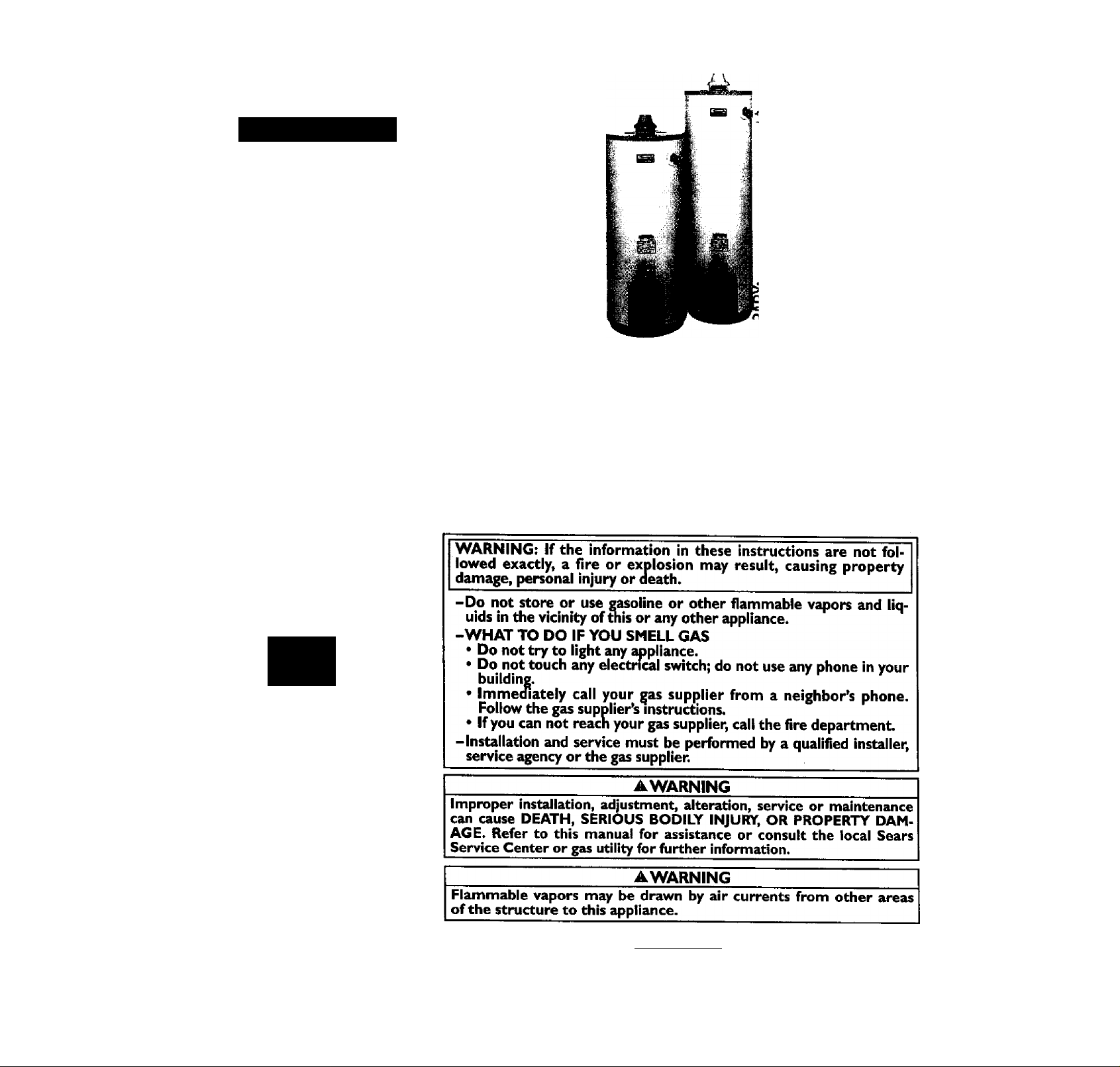
POWER MISERY»9
GAS WATER HEATER
• Safety Instructions • Care and Maintenance
• Installation • Troubleshooting
• Operation • Parts List
For Your Safety
AN ODORANT IS ADDED TO THE GAS USED BY THIS WATER HEATER
HJ
Caution:
Read and Follow
All Safety Rules and
Operating Instructions
Before First Use of
This Product.
Save this Manuai for Future Reference.
Sears, Roebuck and Co., Hoffman Estates, IL 60179 U.S.A.
____________________
A WARNING
_____________________
READ THE GENERAL SAFETY SECTION BEGINNING ON INSIDE
COVER AND THEN THIS ENTIRE MANUAL BEFORE INSTALLING
OR OPERATING THIS WATER HEATER.

Safety Precautions
▲WARNING
Improper installation, adjustment, alteration, service or
maintenance can cause DEATH, SERIOUS BODILY
INJURY, OR PROPERTY DAMAGE. Refer to this manu-
ai for assistance or consult your local Sears Service
Center for further information.
▲WARNING
WATER HEATERS EQUIPPED FOR ONE TYPE GAS
ONLY; This water heater is equipped for one type gas
only. Check the model rating plate near the gas control
valve for the correct gas. DO NOT USE THIS WATER
HEATER WITH ANY GAS OTHER THAN THE ONE
SHOWN ON THE MODEL RATING PLATE. Failure to
use the correct gas can cause problems which can result in
DEATH, SERIOUS BODILY INJURY, OR PROPERTY
DAMAGE. If you have any questions or doubts consult
your gas supplier or local utility.
▲WARNING
INSTALLATIONS IN AREAS WHERE FLAMMABLE LIQ
UIDS (VAPORS) ARE LIKELY TO BE PRESENT OR
STORED (GARAGES, STORAGE, AND UTILITY AREAS,
ETC); Flammable liquids (such as gasoline, solvents,
propane (LP) or butane, etc.), all of which emit flammable
vapors, may be improperly stored or used in such areas.
The gas water heater pilot light or main burner can ignite
such vapors. The resulting flashback and fire can cause
death or serious burns to anyone in the area, as well as
property damage.
If installation in such areas is your only option, then the
installation must be accomplished in a way that the pilot
flame and main burner flame are elevated from the floor
at least 18 inches. While this may reduce the chances of
flammable vapors from a floor spill being ignited, gasoline
and other flammable substances should never be stored or
used in the same room or area containing a gas water
heater or other open flame or spark producing appliance.
NOTE: Flammable vapors may be drawn by air currents
from other areas of the structure to the appliance.
▲WARNING
If this water heater will be used in beauty shops, barber
shops, cleaning establishments, or self-service laundries
with dry cleaning equipment, it is imperative that the
water heater or water heaters be installed so that com
bustion and ventilation air be taken from outside these
areas. Refer to the "Facts to Consider About the
Location" section of this manual and also the latest edi
tion of the National Fuel Gas Code, ANSI Z223.I, also
referred to as NFPA 54 for specifics provided concerning
air required.
▲WARNING
A fire can start if combustible materials such as clothing,
cleaning materials, or flammable liquids are piaced i^nst
or next to the water heater.
▲WARNING
At the time of manufacture this water heater was provid
ed with a combination temperature-pressures relief valve
certified by a nationally recognized testing laboratory
that maintains periodic inspection of produrtion of listed
equipment or materials, as meeting the requirements
for Relief Valves and Automatic Gas Shutoff Devices for
Hot Water Supply Systems, and the latest edition of
ANSI Z2I.22 and the code requirements of ASME. If
replaced, the valve must meet the requirements of local
codes, but not less than a combination temperature and
pressure relief valve certified as meeting the require
ments for Relief Valves and Automatic Gas Shutoff
Devices for Hot Water Supply Systems, ANSI Z21.22 by
a nationally recognized testing iaboratory that maintains
periodic inspection of production of listed equipment or
materials.
The valve must be marked with a maximum set pressure
not to exceed the marked hydrostatic working pressure
of the water heater (ISO Ibs./sq. in.) and a discharge
capacity not less than the water heater input rate as
shown on the model rating plate. (Electric heaters watts divided by 1000 x 3415 equal BTUAHr. rate.)
Your focal jurisdictional authority, while mandating the
use of a temperature-pressure relief valve complying
with ANSI Z2I.22 and ASME, may require a valve model
different from the one fomished with tiie water heater.
Compliance with such local requirements must be satis
fied by the installer or end user of the water heater with
a locally prescribed temperature-pressure relief valve
installed in the designated opening in the water heater in
place of the factory furnished valve.
For safe operation of the water heater, the relief valve
must not be removed from it*s designated opening or
plugged.
The temperature-pressure relief valve must be installed
directly into the fitting of the water heater designated
for the relief valve. Position the valve downward and pro
vide tubing so that any discharge will exit only within 6
inches above, or at any distance below the structural
floor. Be certain that no contact is made with any live
electrical part. The discharge opening must not be
blocked or reduced in size under any circumstances.
Excessive length, over 30 feet, or use of more than four
elbows can cause restriction and reduce the discharge
capacity of the valve.
No valve or other obstruction is to be placed between
the relief valve and the tank. Do not connect tubing
directly to discharge drain unless a 6" air gap is provided,
lb prevent bodily injury, hazard to life, or property dam
age, the relief valve must be allowed to discharge water
in quantities should circumstances demand. If the dis
chaise pipe is not connected to a drain or other suitable
means, the water flow may cause property damage.
The Discharge Pipe:
* Must not be smaller in size than the outlet pipe size of
the valve, or have any reducing couplings or other
restrictions.
• Must not be plugged or blocked.
• Must be of material listed for hot water distribution.
* Must be installed so as to allow complete drainage of
both the temperature-pressure relief valve, and the
discharge pipe.
• Must terminate at an adequate drain.
* Must not have any valve between the relief valve and
tank.

Safety Precautions
AWARNING
A gas water heater cannot operate properly without the
correct amount of air for combustion. Do not install in a
confined area such a closet, unless you provide air as
shown in the "Facts to Consider About the Location” sec
tion. Never obstruct the flow of ventilation air. If you have
any doubts or questions at all, call your gas company.
Failure to provide the proper amount of combustion air
can result in a fire or explosion and can CAUSE DEATH,
CPRimiS Rnmiv ikiii inv nn oonDcnrv r\AMA/:!c
AWARNING
HOTTER WATER CAN SCALD: Water heaters are
intended to produce hot water. Water heated to a tem
perature which wiil satisfy ciothes washing, dish washing,
and other sanitizing needs can scald and permanentiy
injure you upon contact Some peopie are more likeiy to
be permanentiy injured by hot water than others. These
include the elderly, children, the infirm, or physically/mentaily handicapped. If anyone using hot water in your home
fits into one of these groups or if there is a local code or
state law requiring a certain temperature water at the hot
mter tap, tiien you must take special precautions. In addi
tion to using the lowest possible temperature setting that
satisfies your hot water needs, a means such as a mixing
valve, should be used at the hot water taps used by these
people or at the water heater. Mixing valves are available
at plumbing supply or hardware stores. Follow manufac
turers instructions for installation of the valves. Before
changing the factory setting on tiie thermostat, read the
"lemperature Regulation” section in this manual.
AWARNING
Soot build-up indicates a problem that requires correc
tion before further use. Turn “OFF” gas to water heater
and leave “OFF” until repairs are made, because Allure
to correct the cause of the sooting can result in a fire or
explosion causing DEATH, SERIOUS BODILY INJURY,
OR PROPERTY DAMAGE.
AWARNING
This water heater must not be installed directly on car
peting. Carpeting must be protected by a metal or wood
panel beneath the applimce extending beyond the full
width and depth of the appliance by at least 3 inches
(76.2mm) in any direction, or if the appliance is installed
in an alcove or closet, the entire floor must be covered by
the panel. Failure to heed this warning may result in a
fire hazard.
AWARNING
ed thermally or otherwise must be removed if its use
inhibits proper drafting of the water heater.
Thermally Operated Vent Dampers: Gas-fired water
heaters having thermal efficiency in excess of 80% may
produce a relatively low flue gas temperature. Such tem
peratures may not be high enough to properly open ther
mally operated vent dampers. This would cause spill^e of
flue gases and may cause carbon monoxide poisoning.
Vent dampers must bear evidence of certification as com
plying with the latest edition of American National
Standard ANSI Z21.68 {ANSI Z21.66 & 67, respectively,
cover electrically and mechanically actuated vent
dampers). Before installation of any vent damper, consult
your loc^ Sears Service Center or the gas utility for fur
ther information.
—.«V TTtICUI«;i IV l> uperiltk-
AWARNING
* The appliance and its individual shutoff valve must be dis
connect from the gas supply piping system during any
pressure testing of the gas system at test pressures in
excess of /i pound per square inch (3.5kPa).
• The appliance must be isolated from díte gas supply pip
ing system by closing its individual manual shutoff valve
during any pressure testing of the gas supply piping sys
tem at test pressures equal or less than 'A pound per
square inch (3.5kPa).
AWARNING
BEFORE LIGHTING [PROPANE (L.P.) GAS WATER
HEATERS]: Propane (LP.) gas is heavier than air. Should
there be a leak in the system, the gas will settle near the
ground. Basements, crawl spaces, skirted areas under
mobile homes (even when ventilated), closets and areas
below ground level will serve as pockets for the accumula
tion of this gas. Before attempting to light or relight the
water heater’s pilot or turning on a nearby electrical light
switch, be absolutely sure there is no accumulated gas in
the area. Search for odor of gas by sniffing at ground level
in the vicinity of the appliance. If odor is detected, follow
steps indicated at “For Your Safety” on the cover page of
this manual then leave the premises.
AWARNING
Chemical vapor corrosion of the flue and vent system
may occur if air for combustion contains certain chemical
vapors. Spi^ can propellants, cleaning solvents, refHgerator and air conditioner refrigerants, swimming pool
chemicals, calcium and sodium chloride, waxes, bleach,
and process chemicals are typical compounds which are
potentially corrosive.
AWARNING
Obstructed or deteriorated vent systems may present a
serious health risk or asphyxiation.
Safety Precautions continued on page 4.

Safety Precautions
AWARNING
The water heater with draft hood installed must be prop
erly vented to a chimney which terminates outdoors.
Never operate the water heater unless it is vented to the
outdoors and has adequate air supply to avoid risks of
improper operation, explosion or asphjmiation.
AWARNING
Minimum clearances between the water heater and com
bustible construction are I” at the sides and rear, 4" at the
front, and 6" from the vent pipe. Clearance from the top
of the jactwt is 18" on most models. Note that a lesser
dimension may be allowed on some models. Refer to the
label on the water heater adjacent to the gas control valve
for all clearances.
AWARNING
Do not use this appliance if any part of it has been under
water. Immediately call a Sears Service Technician to
in^Kct the appliance and to replace the gas control or any
part of the burner system which has been under water.
ACAUTION
WATER HEATERS EVENTUALLY LEAK: Installation of
the water heater must be accomplished in such a manner
that if the tank or any connections should leak, the flow
of water will not cause damage to the structure. For this
reason, it Is not advisable to install the water heater in an
attic or upper floor. When such locations cannot be
avoided, a suitable drain pan should be installed under
the water heater. Drain pans are available at your local
Sears store. Such a drain pan must be not greater than
11/2 inches deep, have a minimum length and width of at
least 2 inches greater than the water heater dimensions
and must be piped to an adequate drain. The pan must
not restrict combustion air flow. Under no circumstances
is the manufacturer or Sears to be held liable for any
water damage in connection with this water heater.
AWARNING
HYDROGEN GAS: Hydrogen gas can be produced in a hot
water system that has not been used for a long period of
time (generally two weeks or more). Hydrogen gas is
extremely flammable and explosive. To prevent the possi
bility of injury under these conditions, we recommend the
hot water faucet be opened for several minutes at the
kitchen sink before any electrical appliances which are
connected to the hot water system are used (such as a
dishwasher or washing machine). If hydrogen gas is pre
sent, there will probably be an unusual sound similar to air
escaping through the pipe as the hot water faucet is
opened. There must be no smoldng or open flame near
the faucet at the time it is open.
AWARNING
INSULATING JACKETS: When installing an external
water heater insulation jacket on a gas water heater:
• DO NOT cover the temperature-pressure relief valve.
• DO NOT put insulation over any part of the top of the
gas water heater.
• DO NOT put insulation over the gas control valve or gas
control valve/bumer cover, or any access areas to the
burner.
• DO NOT let insulation around the gas water heater to
get within 8 inches of the floor (air must get to the
burner).
• DO NOT cover or remove operating instructions, and
safety related warning labels and materials affixed to the
water heater.
Failure to heed this will result in the possibility of a fire or
explosion.

Table of Contents
Safety Precautions...............................................................................
Table of Contents................................................................................. 3
Customer Responsibilities.................................................................. 6
Product Specifications
........................................................................
^
Materials and Basic Tools Needed..........................................................
Materials Needed................................................................................................................................................................................................ ^
Basic Tools........................................................................................................................................................................................................... ^
Installation Instructions
Removing the Old Water Heater....................................................................................................................................................................... g
Facts to Consider About the Location............................................................................................................................................................... c,
Combustion Air and Ventilation for Appliances in Unconfined Spaces......................................................................... j q
Combustion Air and Ventilation for Appliances in Confined Spaces............................................................................................................ 10
Water Piping..................................................................................................................................................................................................... jj
Temperature-Pressure Relief Valve.................................................................................................................................................................. j2
Filling the Water Heater..............................................................................................................................
...........................................................................................................................................................ZZZZZ'Z'"
Gas Piping...................................................................................................................................................................................................!Zi4-15
Installation Checklist................................................................................................................. j g
......................................................................
......................................................
.............................
.
13-14
Operating Instructions.................................................................. 17.15
Lighting..................................................................................................................................................................................Z""Z"Z!Z^I!!”Zi7-18
Temperature Regulation................................................................................................................................................................................... 19
Service and Adjustment................................................................................................................................................20-22
Tank (Sediment) Cleaning................................................................................................................................................................................ 2q
Venting System Inspection............................................................................................................................................................................ 2Q
Burner Inspection.............................................................................................................................................................................................. 2o
Burner Cleaning............................................................................................................................................................................................... 2q
L.R Gas Control Valve & Burner Assembly Replacement Information........................................................................................................ 21
Diainir^............................................................................................................................................................................................................... 21
Tempetature-Pressure Relief Valve Operation................................................................................................................................................ 21
Drain Valve Washer Replacement................................................................................................................................................................... 22
Housekeeping..................................................................................................................................................................................................... 22
..........................•;............................................................................................................
.
j 3
Troubleshooting Guide.......................................................................23-25
Start Up Conditions............................................................................................................................................................................................ 23
Condensation.................................................................................................................................................................................................... 23
Smoke/Odor...................................................................................................................................................................................................... 23
Thermal Expansion.......................................................................................................................................................................................... 23
Strange Sounds.................................................................................................................................................................................................. 23
Operational Conditions...................................................................................................................................................................................... 24
Smelly Water.................................................................................................................................................................................................... 24
Air in Hot Water Faucets................................................................................................................................................................................. 24
High Temperature Shut Off System............................................................................................................................................................... 24
Not Enough or No Hot Water......................................................................................................................................................................... 24
Water is too Hot............................................................................................................................................................................................... 24
Leakage Checkpoints......................................................................................................................................................................................... 25
Parts Order List...................................................................................28-35

Customer Responsibilities
Thank You for purchasing a Sears water heater.
Properly installed and maintained, it should give you years of
trouble free service. If you should decide that you want the new
water heater professionally installed by Sears call the local Sears
Service Center or any Sears store. They will arrange for prompt,
quality installation by Sears authorized contractors.
Abbreviations Found In This Instruction Ivbumal
I.A.S. - International Approval Services, A Division of CSA
A.N.S.I. - American National Standards Institute
N.F.P.A. - National Fire Prevention Association
AWARNING
This gas-fired water heater is design certified by the
International ApptwaJ Services, A Dhision of CSA under
American National Standard/CSA Standard for Gas Water
Heaters ANS Z2I.I0.I • CSA 4.1 (latest edition). The
installation must conform with this manual, Local Codes
and with the latest edition of the National Fuel Gas Code,
ANSIZ223.I.
This publication is available from your local government or
public library, gas company, or by writing NFPA,
Batterymarch PaHc, Quincy, MA 02269.
Read the “Safety Precautions” section, pages 2 through 4 of
this manual first and then the entire manual carefully. If you
don’t follow the safety rules, the water heater will not operate
properly. It could cause DEATH, SERIOUS BODILY
INJURY AND/OR PROPERTY DAMAGE.
This manual contains instructions for the installation, opera
tion, and maintenance of the gas-fired water heater. It also
contains warnings through out the manual that you must read
and be aware of. All warnings and all instructions are essential
to the proper operation of the water heater and your safety.
Since we cannot put eveiything on the first few pages, READ
THE ENTIRE MANUAL BEFORE ATTEMPTING TO
INSTALL OR OPERATE THE WATER HEATER.
The installation must conform with the instructions in this
manual; gas company rules; and Local Codes, or in the
absence of Local Codes, with the latest edition of the National
Fuel Gas code, ANSI Z223.1, also referred to as NFPA 54.
This publication is available from your local government or
public library or gas company or by writing NFPA,
Batterymarch Park, Quincy, MA 02269.
If after reading this manual you have any questions or do not
understand any portion or the instructions, call the Scars
Service Center.
Carefully plan the place where you are going to put the water
heater. Correct combustion, vent action, and vent pipe instal
lation are very important in preventing death from possible
carbon monoxide poisoning and fires.
Examine the location to ensure the water heater complies with
the “Facts to Consider About the Location” section in this
manual.
For California installation this water heater must be braced,
anchored, or strapped to avoid falling or moving during an
earthquake. See instructions for correct installation proce
dures. Instructions may be obtained from your local dealer,
wholesaler, public utilities or California Office of the State
Architect. 400 P Street, Sacramento, CA 95814.
Product Specifications
TANK
MODEL NUMBER
CAPACITY
IN GALLONS
153.337113
153.337162
153.337213 40
153.337262
153.337362 30 NATURAL 40,000 40.9
153.337413
153.337462 40 NATURAL 40,000 40.9
153-337513 50 NATURAL 40,000
153.337562
153.337613
153-337662
153.337762 50 NATURAL 52,500 53.7
153.337862
153.337960
50 NATURAL 40,000
50 NATURAL 40,000 40.9
40 NATURAL 40,000 40.9
40 NATURAL 40,000 40.9
50 NATURAL 40,000 40.9 3" or 4”
65
65
65
40
TYPE
OF
GAS
NATURAL 40,000
NATURAL 40,000 40.9 3" or 4"
NATURAL 40,000
NATURAL 50,000
PROPANE 40,000 40.9
B.T.U.
RATE
RECOVERY
RATE GALS.
PER HOUR
@90“FRISE
40.9
40.9
40.9 3" or 4"
40.9 3" or 4"
51.2
MINIMUM
VENT
PIPE
3" or 4"
3” or 4"
3" or 4"
3" or 4"
3" or 4"
3" or 4"
3" or 4" 18" 58/4"
4" 20"
4" 22"
3" or 4" 18"
DIMENSIONS IN INCHES
HEIGHT TO
DIAMETER
22"
22"
20"
20”
16"
18" 58/7’
20" 58"
20" 58"
22" 59/"
22"
JACKET TOP
49"
49”
47H"
47/2"
m"
59/2"
58/"
59/2"
58/"
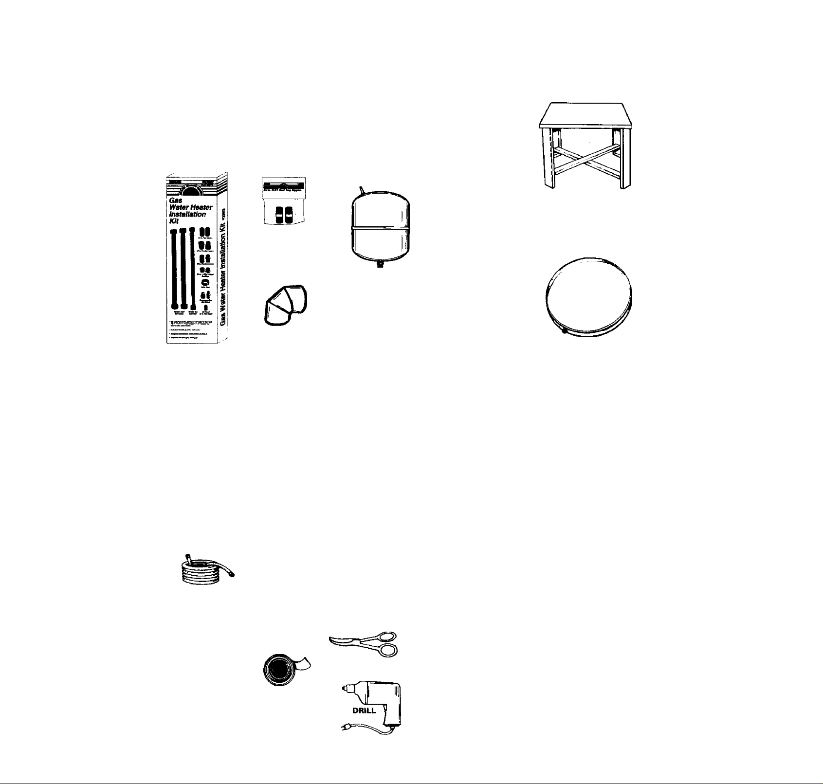
Materials and Basic Tools Needed
Materials Needed
To simplify the installation Sears has available the installation
parts shown below. You may or may not need all of these materi
als, depending on your type of installation.
WATER HEATER HEAT
TRAPS HELP REDUCE
HEAT LOSS DUE TO
THERMAL SYPHONING
VENT ELBOW
WATER HEATER INSTAL
LATION KIT WITH FLEXI
BLE CONNECTORS FOR
3/4" OR 1/2" THREADED
OR COPPER PLUMBING
EXPANSION TANKS
FOR THERMAL
EXPANSION CONDI
TIONS AVAILABLE IN
2 GAU.ON AND 5
GALLON CAPACITY
THROUGH LOCAL
SEARS STORE OR
SERVICE CENTERS
c
VENT PIPE
FLEXIBLE WATER
HEATER GAS CON
NECTOR WITH
FITTINGS
mi
WATER HEATER STAND 24"x24"xl8"
FOR USE WITH WATER HEATERS
INSTALLED IN RESIDENTIAL
GARAGES HAVING A DIAMETER 24"
OR LESS AND A RATED CAPACITY 75
GALLONS OR LESS
jSi
DRAIN PANS AVAILABLE IN 20"
DIAMETER FOR WATER HEATERS
HAVING A DIAMETER 18" OR LESS
AND AVAILABLE IN 28" DIAMETER
FOR WATER HEATERS HAVING A
DIAMETER 26" OR LESS
Basic Tools
You may or may not need all of these tools, depending on your
type of installation. These tools can be purchased at your local
S^s store.
• Pipe Wrenches (2) 14"
• Screwdriver
• Tin Snips
• 6 Foot Tape of Folding Rule
• Garden Hose
• DnII
• Pipe dope or Teflon Tape
GARDEN HOSE
SLOT-HEAD SCREWDRIVER
PHILLIPS SCREWDRIVER
PIPE DOPE (SQUEEZE TUBE)
USE FOR WATER AND
i
iAS CONNECTIONS)
6 FOOT TAPE
ROLL OF TEFLON TAPE
(USE ONLY ON WATER
CONNECTIONS)
PIPE
WRENCH
TIN SNIPS
ADDITIONAL TOOLS NEEDED
WHEN SWEAT SOLDERING
• Tubing Cutters or Hacksaw
• Propane Torch
• Soft Solder
• Solder Flux
• Emery Cloth
• Wire Brushes
\
HACKSAW
A
3/4" WIRE BRUSH
in" WIRE BRUSH
PROPANE
TORCH
ROLL OF LEAD FREE
SOFT SOLDER
ROLL OF EMERY
CLOTH
SOLDER FLUX
TUBING
CUTTER
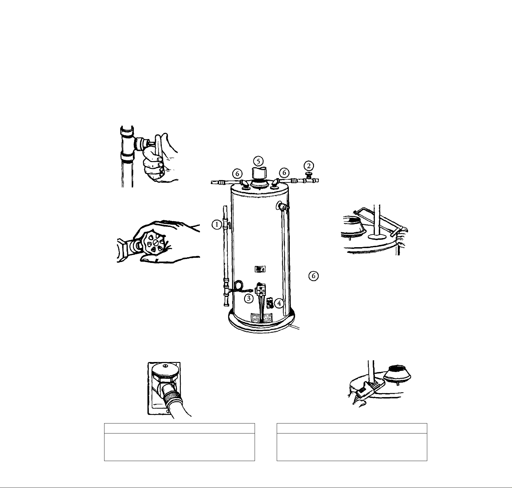
Installation Instructions
Removing the Old Water Heater
^^Turn “OFF” the gas supply to the water heater.
AWARNING
If the main gas line shutoff serving all gas appliances is
used, also shut “off’* the gas at each appliance. Leave all
gas appliances shut “off" until the water heater insolation
is complete.
^^Turn “OFF” the water to the water
'“^heater. Some installations require that
the watet be turned off to the entire
house.
Disconnect the vent pipe from the draft hood where
©
they connect to the water heater. In most installations
the vent pipe can be lifted off after any screw or other
attached devices are removed. Dispose of the draft
hood. The new water heater has the draft hood which
must be used for proper operation.
©
If you have copper piping to the water
heater, the two copper water pipes can
be cut with a hacksaw approximately
four inches away from where they con
nect to the water heater. This will avoid
cutting off the pipes too short.
Additional cuts can be made later if nec
essary. Disconnect the temperature-pres
sure relief valve drain line. When the
water heater is drained, disconnect the
hose from the drain valve. Close the
drain valve. The water heater is now
completely disconnected and ready to be
removed.
{3)Cbeck again to make sure the ^ supply
'■ ^is “OFF to the water heater. Then dis
connect the gas supply connection from
the gas control valve.
(4) Attach a hose to the water heater drain
valve and put the other end in a floor
drain or outdoors. Open the water heater
drain valve. Open a nearby hot water
faucet which will relieve pressure in the
water heater and speed draining.
AWARNING
The water passing out of the drain valve may be extremely
hot. To avoid being scalded, mate sure all connections are
tight and that the water flow is directed away from any
person.
b. If you have galvanized pipe to the water
heater, loosen the two galvanized pipes
with a pipe vnrench at the union in each
line. Also disconnect the piping remain
ing to the water heater. These pieces
should be saved since they may be need
ed when reconnecting the new water
heater. Disconnect the temperature-pres
sure relief valve drain line. When the
water heater is drained, disconnect the
hose from the drain valve. Close the
drain valve. The water heater is now
completely disconnected and ready to be
removed.
A CAUTION
Mineral buildup or sediment may have accumulated in the
old water heater. This causes the water heater to be much
heavier than normal and this residue, if spilled out, could
cause staining.
Installation Instructions (cont’d)
Facts to Consider About the Location
You should carefully choose an indoor location for the new
wat^ heater, because the placement is a very important consid
eration for the safety of the occupants in the building and for
the most economical use of the appliance. This water heater is
not for use in mobile homes or outdoor installation.
Whether replacing an old water heater or putting the water
heater in a new location, the following critical points must be
observed. '
• The location selected should be indoors as close as practical
to the gas vent or chimney to which the water heater vent is
going to be connected, and as centralized with the water pip
ing system as possible. The water heater, as all water heaters,
will eventually leak. Do not install without adequate
drainage provisions where water flow will cause damage.
A CAUTION
WATER HEATERS EVENTUALLY LEAK: Installation of the
water heater must be accomplished in such a manner that if
the tank or any connections should ieak, the flow of water will
not cause damage to the structure. For this reason, it is not
advisable to install the water heater in an attic or upper floor.
When such locations cannot be avoided, a suitable drain pan
should be installed under the water heater. Drain pans are
available at your local Sears store. Such a drain pan must be
not greater titan I '/i inches deep, have a minimum length and
width of at least 2 inches greater than the water heater dimen
sions and must be piped to an adequate drain. The pan must
not restrict combustion air flow. Under no circumstances is the
manufecturer or Sears to be held liable for any water damage
in connection with this water heater.
AWARNING
INSTALLATIONS IN AREAS VWERE FLAMMMLE UQUIDS
(VAPORS) ARE LIKELY TO BE PRESENT OR STORED
(GARAGES, STORAGE, AND UTILITY AREAS, ETC):
Flammable liquids (such as gasoline, solvents, propane (LP) or
butane, etc.), all of which emit flammable vapors, may be
improperiy stored or used in such areas. The gas water heater
pilot light or main burner can ignite such vapors. The resulting
flashback and fire can cause death or serious bums to anyone in
the area, as well as property dam^.
If installation in sudi areas is your only option, then the installa
tion must be accomplished in a way that the pilot flame and
main burner flame are elevated from the floor at least 18 inches.
While thb rnay reduce the chances of flammable vapors from a
floor spill being ignited, gasoline and other flammable substances
should never be stored or used in the same room or area con
taining a gas water heater or other (q>en flame or qiark produc
ing appliance.
NOTE Flammable vapors may be drawn by ar currents from
other areas of the structure to the appliance.
awarKiing
Propellants of aerosol sprays and volatile compounds, (clean
ers, chlorine based chemicals, refrigerants, etc.) in addition to
being highly flammable in many cases, will also change to cor
rosive hydrochloric acid when expoUd to the combustion
products of the water heater. The results can be hazardous,
and also cause product feilure.
The location selection must provide adequate clearances for ser
vicing and proper operation of the water heater.
AWARNING"^
This heater must not be installed directly on carpeting.
Carpeting must be protected by a metal or wood panel
beneath the appliance extending beyond the full width and
depth of the appliance by at least 3 inches (76.2mm) in any
direction, or if the appliance is installed in an alcove or closet,
the entire floor must be covered by the panel Failure to heed
this warning may result in a fire hazard.
AWARNING
Minimum clearances between the water heater and com
bustible construction are I" at the sides and rear, 4" at the
front, wd 6" from the vent pipe, aearance from the top of the
jacket is 18" on most models. Note that a lesser dimension may
be allowed on some models. Refer to the label on the water
heater adjacent to the gas control valve for :dl clearances.
12* MAX,
pIEFl
VENTILATION
AIR
OPENINGS
Figure I
IIOPH"!
I^wnimbrri I
12" MAX.
TOP VIEW
WI°Hc5Ì?é8oR
I'MIN.
I
!■ MIN,
WITH OOOR
eECTANGULAel 3"
AIROUCT I MIN.
AIR DUCT
AWARNING
A gas water heater cannot operate properly without the cor
rect amount of air for combustion. Do not install in a confined
area such a closet, unless you provide air as shown in Figures
1-5. Never obstroct the flow of ventilation air. If you have any
doubts or questions at all, call your gas company, fêlure to pro
vide the proper amount of combustion air can result in a fire or
explosion and can cause DEATH, SERIOUS BODILY INJURY
OR PROPERTY DAMAGE
AWARNING
If this water heater will be used in beauty shops, barber shops,
cleaning establishments, or self-service laundries with dry
cleaning equipment, it is imperative that the water heater or
wrater heaters be installed so that combustion and ventilation
air be taken from outside these areas. Refer to the “Facts to
Consider About the Location" section of this manual and also
tite latest edition of the National Fuel Gas Code, ANSI Z223.I,
also referred to as NF№ 54 for specifics provided concerning
air required.

Installation Instructions (cont’d)
Combustion Air and Ventilation
for Appliances Located in
Unconfined Spaces
Unraiifiaed Space is a space whose volume is not less than 50
cubic feet per 1,000 Btu per hour of the aggregate input rating
of all appliances installed in that space. Rooms communicating
directly with the space in which the appliances are installei
through openings not furnished with doors, are considered a
part of the unconfined space
In unconfined spaces in buildings, infiltration may be adequate
to provide air for combustion, ventilation and dilution of flue
gases. However, in buildmgs of tight construction (for example,
weaker stripping, heavily insulated, caulked, vapor barrier, etc.),
additional^ air may need to be provided using the methods
described in Combustion Air and Ventilation for Appliances
Located in Confined Spaces, b.
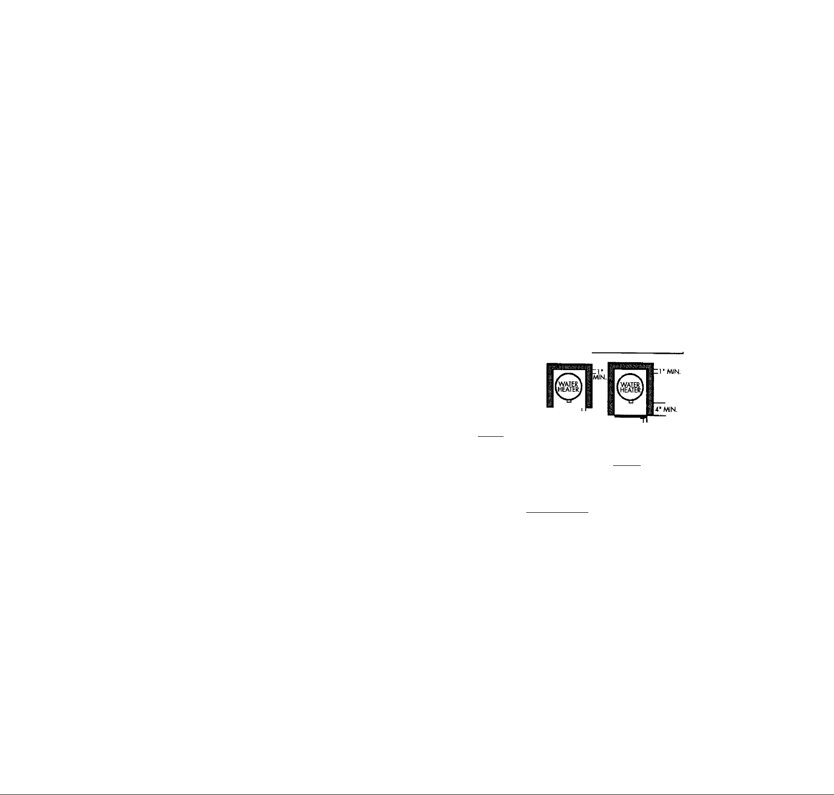
Combustion Air and Ventilation
for Appliances Located in
Confined Spaces
^nfioed Space is a space whose volume is less than 50 cubic
feet per 1,000 Btu per hour of the aggregate input rating of all
appliances installed in that space,
a. ALL AIR FROM INSIDE BUILDINGS:
(See I^e 9 Figure 1, and F^ure 2 below)
The confined space shall be provided with two permanent
openings communicating direedy with an additional room(s)
of sufficient volume so that the combined volume of all
spaces meets the criteria for an unconfined space. The total
input of all ^ utilization equipment installed in the com
bined space shall be considered in making this determination,
^ch openii^ shall have a minimum free area of one square
inch per 1,000 BT^ per hour of the total input raring of all
gas utilization equipment in the confined space, but not less
than 100 square inches. One opening shall commence within
12 inches of the top and one commencing within 12 inches
of the bottom of the enclosure.
CMMN6Y OH (MS VENT
1. 'pCTien direaly communicating with the outdoors, each open
ing shall have a minimum free area of 1 square inch per 4,000
BTU per hour of total input rating of all equipment in the
enclosure. (See Figure 3.)
2. When communicating with the outdoors through vertical
ducts, each opening shall have a minimum free area of 1
square inch per 4,000 BTU per hour of total input rating of
all equipment in the enclosure. (Sec Figure 4.)
Figure 4
3. When communicating with the outdoors through horizontal
ducts, each opening shall have a minimum fee area of 1
uare inch per 2,000 BTU per hour of total input rating of
equipment in the enclosure. (See Figure 5.)
a
Ol/aCTMACIUCT
~Flgur« 2
• ALL AIR FROM OUTDOORS: (see Figures 3-5)
The confined space shall be provided with two permanent
openings, one commencing within 12 inches of the top and
one commencing within 12 inches from the bottom of the
enclosure. The openings shall communicate directly, or by
ducts, wiA the outdoors or spaces (crawl or attic) that freely
communicate with the outdoors.
Figure 3
Figure 5
4. When ducts arc used, they shall be of the same cross-sectional
area as the free area of the openings to which they connect.
The minimum short side dimension of rectangular air ducts
shall not be less than 3 inches. (See Figure 5.)
5. Louvers and Grilles: In calculatii^ free area, consideration
shall be given to the blocking effect of louvers, grilles or
screens protecting opening. Screens used shall not be smaller
than inch mesh. If the free area through a design of louver
or grille is known, it should be used in calculating the size
opening rec^ired to provide the free area specified. If the
design and free area is not known, it may be assumed that
wood louvers will be 20-25 percent fee area and metal louvers
and grilles will have 60-75 percent free area. Louvers and
grilles shall be fixed in the open position or interlocked with
the equipment so that they are opened automatically during
equipment operation.
6. Special Conditions Created by Mechanical Exhausting or
Fireplaces: Operation of exhaust fans, ventilation systems,
clothes dryets or fireplaces may create conditions requiring
special attention to avoid unsatisfretory operation of installed
gas utilization equipment. '
10
NTT AM DUCT
Installation Instructions (cont’d)
Water Piping
_____________
HOTTER WATER CAN SCALD: Witer heat«? are intended to
pn^uce hot water. >№ter heated to a temperature which will
satisfy dothes vrashingi dish washing, and other sanitizing needs
can scald and permanently injure you upon contact Some peo>
pie are more lilcdy to be permanently Injured by hot water than
others. These include die elderl]^ children, the infirm, or pfiyskal-
lyimentally handicapped. If anyme using hot water in your home
fits one of these groups or if there is a local code or state law
requiring a certain temperature water at the hot water rap, then
you must take special precautions. In addition to using the lowest
possible tempei^re setting that satisfies your hot water needs,
a means such as a mbung valve, should be used at the hot vrater
taps used by these people or at the water heater. Mixing vdves
are available at plumbing supply or hardware stores. Follow manuAuturers Instructions for installation of the valves. Before
changing the factory setting on the thermostat, read the
‘Temperature Regulation’* section in this manual.
This water heater shall not be connected to any heating systems
or component(s) used with a non-potable water heating
appliance.
If a water heater is installed in a closed water supply system;
such as one having a back-flow preventer, check valve, water
meter with a check valve, etc... in the cold water supply; means
shall be provided to control thermal expansion. Contact the
local utility or local Sears Service Center on how to control this
situation.
A WARNING
___________
__
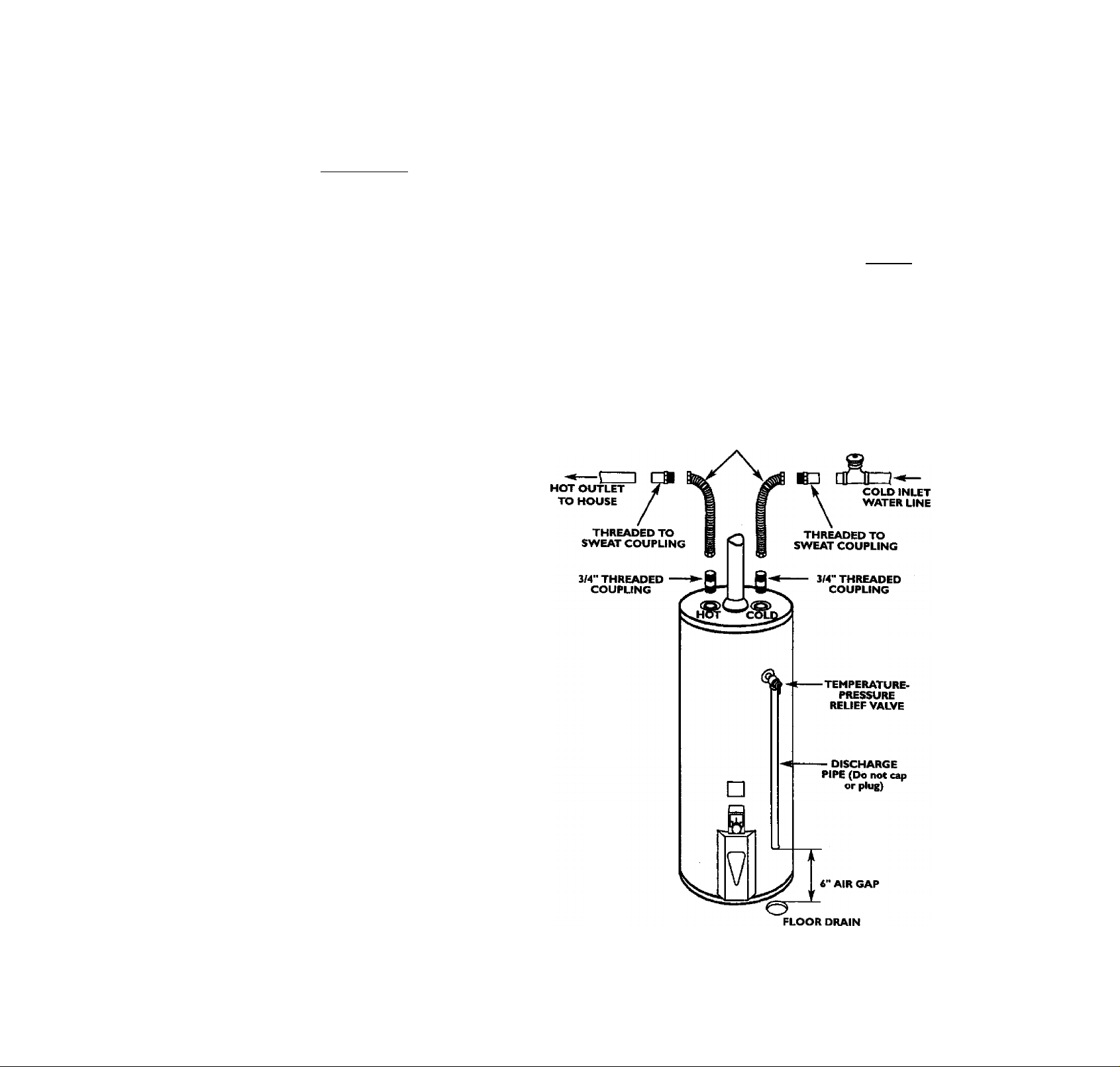
^ok at the tim cover of the water heater. The cold water
inlet is marked cold. Put two or three turns of teflon tape
around the threaded end of the threaded-to-sweat coupling
and around both ends of the Y*" threaded nipple. Using flexi
ble connectors, connect the cold water pipe to the cold water
inlet of the water heater.
NOTE: This water heater is super insulated to minimiT..
heat loss from Ac tank. Further reduction in heat loss
can be accomplished by insulating Ae hot water lines
from Ae water heater.
INSTALLATION COMPLETED USING
SEARS INSTALLATION KIT
FLEXIBLE
WATER
CONNECTORS
SHUTOFF
VALVE
NOTE: To protect against untimely corrosion of hot and
cold water fittings, it is strongly recommended that di-elec
tric unions or couplings he installed on this water heater
when connected to copper pipe.
The illustration shows the attachment of the water piping to the
water heater. The water heater is equipped with Yi inch water
connections.
NOTE: If using copper tuhing, solder tubing to an adapter
l^ore attaching the adapter to the cold water inlet connec
tion. Do not solder the cold water supply line direcdy to the
cold water inlet. It will harm the dip tube and damage the
tank.
• Look at the top cover of the water heater. The water oudet is
marked hot. Put two or three turns of teflon tape around the
threaded end of the threaded-to-swcat coupling and around
both ends of the Y* threaded nipple. Using flexible connec
tors, connect the hot water pipe to the hot water outlet on
the water heater.
II

Installation Instructions (cont*d)
Temperature-Pressure Relief Valve
AWARNING
At the time of manufacture this vnter heater was provided
with a combination temperatune^ressures relief valve certified
b/ a nationally recognized testing laboratory that maintains
periodic inspection of production of listed equipment or mate
rials, as meeting the requirements for Relief Valves and
Automatic Gas Shutoff De^es for Hot Water Supply Systems,
and the latest edition of ANSI Z2I.22 and the code require
ments of ASME. If replaced, the valve must meet the require
ments of local codes, but not less than a combination tempera
ture and pressure relief valve certified as meeting the require
ments for Relief Valves and Automatic Gas Shutoff Devices for
Hot Water Supply Systems, ANSI Z2I.22 by a nationally recog
nized testing laboratory that maintains periodic inspection of
production of listed equipment or materials.
The valve must be marked with a maximum set pressure not
to exceed the marked hydrostatic working pressure of the
water heater (ISO IbsJsq. in.) and a discharge capacity not less
than the water heater input rate as shown on the model rating
plate. (Electric heaters ■ watts divided by 1000 x 3415 equal
BTU/Hr. rate.)
Your local jurisdictional authority, while mandating the use of a
temperature-pressure relief valve complying with ANSI Z21.22
and ASME, may require a valve model different frtmi the one
fiirnished the water heater.
Compliance vrith such local requirements must be satisfied by
the installer or end user of the water heater with a locally pre
scribed temperature-pressure relief valve installed in the deslg
nated opening in the water heater in place of the factory fur
nished ràlve.
For safe curation of the water heater, the relief valve must not
be removed from itis desifpiated opening or plugged.
The temperature-pressure relief valve must be installed directly
into the fitting of the water heater designated for the reftef valve.
Position the valve downvwud and provide tubing so that any dischai^ will exit only witiiin 6 inches above, or at any distance
below the structiiral floor. Be certain that no contact is made
with any live electrical part The discharge opening must not be
blocked or reduced in size under any circumstances. Excessive
length, over 30 feet or use of more tiian four elbows can cause
restriction and reduce the discharge capacity of the valve.
No valve or other obstruction is to be placed between the relief
valve and the tank. Do not connect tubing directly to discharge
drain unless a fi" air gap is provided. To prevent bodily injury, haz
ard to life, or property damage, the relief valve must be allowed
to discharge water in quantities should circumstances demand. If
the discharge pipe is not connected to a drain or other suitable
means, the water flow may cause property damage.
The Discharge Pipe;
• Must not be smaller in size than the outlet pipe size of the
valve, or have any reducing couplings or other restrictions.
• Must not be plugged or blocked.
• Must be of material listed for hot water distribution.
• Must be installed so as to allow complete drainage of both
the temperature-pressure relief valve, and the discharge
pipe.
• Must terminate at an adequate drain.
• Must not have any valve between the relief valve »id tank.
AWARNING
The temperature-pressure relief valve must be manually
operated at least once a year. Caution should be taken to
ensure that (I) no one Is in front of or around the outlet of
the temperature-pressure rriief valve dlsdiaige line, and (2)
the water manually discharged will not cause any bodily
injury or property damage because the water may be
extremely hot
If after manually operating the valve, it foils to completely
reset and continues to release water, immediately dose the
cold water inlet to the water heater, follow the draining
insteuctions, and replace the temperature-pressure relief
valve with a new one.
COLD
TEMPERATURE-
PRESSURE
RELIEF VALVE
DISCHARGE PIPE
{Do not cap or plug)
6" AIR GAP
RELIEF VALVE OPENING
At the time of manufectu«, this water heater was provided with a lombinatior temperature.prej$ure relief valve listed as compl)dn2 with the standard for relief valves and
automatic gas shut-off devices for hot water supply systems, ANSI 221.12. for safe
operation of the water heater, the relief valve must not be removed from its designated
point Of fostailacion or plugged.
Your loc^ [urisdictional authority, while mandating the use of a temperature-pressure
relief valve complying with ANSI Z21.22 and ASME may require a valve model different
from the one furnished with the water heater.
Compiiarce with such local requirements must be satisfied by the installer or end user
of the water heater with a locally prescribed temperature^iressure relief valve installed
in the designated opening in the water heater.
See manual heading -‘Temperature-Pressure Relief Valves" for installation and mainte
nance of relief valve, discharge line, and ocher safety precautions.
12

Installation Instructions (cont*d)
Filling the Water Heater
A CAUTION
Never use this water heater unless it is completely filled wnth
water. 1b prevent damage to the tank, the tank must be filled
with water. Water must flow from the hot water faucet
before turning "ON" gas to the water heater.
To fill the water heater with water:
• Close the water heater drain valve by turning the handle to
the right (clockwise). The drain valve is on the lower front of
the water heater.
• Open the cold water supply valve to the water heater.
NOTE: The cold water supply valve must be left open
when the water heater is in nse.
• To insure complete filling of the tank, allow air to exit by
opening the nearest hot water faucet. Allow water to run
until a constant flow is obtained. This will let air out of the
water heater and the piping.
• Check ail new water piping for leaks. Repair as needed.
Venting
AWARNING
VENT DAMPERS - Any vent damper, whether it is operated
thermally or otherwise must be remov^ if its use inhibits prop
er drafting of the water heater.
Thermally Operated Vent Dampers: Gas-fired water heaters
having thermal efficienqr in excess of 80% may produce a rela
tively low flue gas temperature. Such temperatures may not be
high enough to properly open thermally operated vent
dampers. Ibis would cause splll^ of flue ga^ and may cause
carbon monoxide poisoning.
Vent dampers must bear ^dence of certification as complying
with the latest edition of American National Standard ANSI
Z2I.68 (ANSI Z2I.66 & 67, respectively, cover electrically and
mechanically actuated vent dampers). Before installation of any
vent damper, consult your loc^ Sears Service Center or the gas
utility for further information.
AWARNING
To insure proper venting of this gasdired water heater, the
correct vent pipe diameter must ^ utiHxed. Any additions or
ddetions of ot^ gas appliances on a common vent witii this
water heater may adversely affect the operation of the water
heater. Consult tiie local Sears Service Center or gas utility if
any such changes are planned.
For proper venting in certain installations, a larger diameter vent
pipe may be necessary. Due to great variances in installations,
unforeseeable by the manufaaurer of the water heater, той must
consult your gas company to aid you in determining the proper
venting for your water heater from the vent tables in the latest edi
tion of the National Fuel Gas Code ANSI Z223.1, also referred to
as NFPA 54.
Check the venting system for signs of obstruction or deterioration
and replace if needed. .
The combustion and ventilation air ftow must not be obstructed.
AWARNING
Obstructed or deteriorated vent systems may present a serious
health risk or asphyxiation.
Place the draft hood legs in the receiving holes on the top of
the water heater. The legs will snap in the holes to give a tight
fit.
Place the vent pipe over the draft hood. With the vent pipe in
position, drill a small hole through both the vent pipe and
draft hood. Secure them together with a sheet metal screw.
DRAFT HOOD
DRAFT Н<ЮО N
t
r
VENT.
SCRE'
---
i ,-CHIMNEY
1 ♦
I , Dnni
к- I n i J^
VENT TO OUTDOORS OR
DRAFT HOOD
AWARNING
The water heater with draft hood installed must be properiy
vented to a chimney which terminates outdoors. Never oper^
ate the water heater unless it is vented to the outdoors wid has
adequate air supply to avoid risks of iniproper operation, explo
sion or asphyxiation.
AWARNING
The vent pipe from the vrater heater must be no less than the
diameter of the draft hood outlet on the water heater, and
must slope upward to the chimney at least % inch per linear
foot
13

Installation Instructions (cont’d)
Venting (cont’d)
All vent gases must be completely vented to the outdoors of the
structure (dwelling). Instalf only the draft hood provided with
the new water heater and no other draft hood.
Vent pipes must be secured at each joint with sheet metal screws.
TO
CHIMNEY
MIN. /. INCH
RISE PER LINEAR
FOOT
VENT PIPE INSTALLATION
There must be a minimum of 6" clearance between single wall
vent pipe and any combustible material. Fill and seal any clear
ance Dctween single wall vent pipe and combustible material
with mortar mix, cement, or other noncombustible substance.
For other than single wall, follow vent pipe manufacturers clear
ance specifications. To insure a tight fit of the vent pipe in a
brick chimney, seal around the vent pipe with mortar mix
cement.
▲WARNING
Failure to have required clearances between vent piping and
combustible material will re^lt in a fire hazard.
▲WARNING
Be sure vent pipe is properly connected to prévoit escape of
dangerous flue gases which could cause deadly asphyxiation.
Gas Piping
▲WARNING
Make sure tiie gas supplied is the same type listed on the
model rating pi^. The inlet gas pressure must not exceed
10.5 in, water column (2.6kPa) for natural gas or 13 in. water
column (3,2kPa) for propane (LP.) gas. The mmimum inlet
gas pressure iisbed on the model rating plate is for (he pur
pose of input adjustm«it
▲WARNING
If the gas control valve is subjected to pressures exceeding
pound per square inch (3,5k^), the damage to the gas con
trol valve could result in a fire or explosion frwn leaking gas.
▲WARNING
If the main gas line shutoff serving all gas api^iances is used,
also turn “off” the gas at each appliance. Lem all gas appli
ances shut off until ¿e water heater installation is complete.
A gas line of sufficient size must be run to the water heater.
Consult the latest edition of National Fuel Gas Code ANSI
Z223.1, also referred to as NFPA 54 and the gas company con
cerning pipe size.
There must be:
• A readily accessible manual shut off valve In the gas supply line
serving the \rater heater, and
• A drip lee (sediment trap) ahead of the gas control valve to help
prevent tfirt and foreign materiak from entering the gas control
valve,
• A flexible gas connector or a ground joint union between the
shutoff valve and control valve to permit servidi^ of the unit.
▲WARNING
Chemical vapor corrosion of the flue and vent system may
occur if air Ibr combustion contains certain chemical vapors.
Spray can propellants, cleaning solvents, refrigerator and air
conditioner refrigerants, swimming pool chemicals, calcium
and sodium chloride, waxes, bleach, and process chemicals are
tyi^cal compounds v^ich are potentially corrosive.
Be sure to check all the gas piping for leaks before lifting the
water heater. Use a soapy water solution, not a match or open
flame. Rinse off soapy solution and wipe dry.
Standard Modeb are for installation up to 3,300 feet above sea
level.
High Altitude Models are for installation from 3,300 to 5,500
feet above sea level.
If a standard model is installed above 3,300 feet or a high altitude
model is installed above 5,500 feet, the input rating must be
reduced at the rate of 4 percent for each 1,000 feet above sea level.
Contact your local Sears Service Center or gas utility for further
information.
▲WARNING
The appliance and its gas connection must be leak tested
before facing the appliance in operation.
14

Installation Instructions (cont*d)
AWARNING
• The appliance and its individual shutoff valve must be discon
nected from the gas supply piping system during any pressure
testing of the gas system at test pressures in excess of '/i
poitftd per square imh (3.5kPa).
• The ap^iance must be isolated from the gas supply piping sys
tem 1^ dosing its individual manual shu^ vdrc during any
pressure testing of the gas supply piping system at test pres
sures equal or 1^ than 9j pound per square inch (3.5ld*a).
AWARNING
Use pipe joint compound or teflon tape marked as being
resistent to the action of peteoleum |Tro(nne (LR)] gases.
SEDIMENT TRAP
A sediment trap shall be installed as close to the inlet of the
water heater as practical at the time of water heater installation.
The sediment trap shall be either a tee fitting with a capped nip
ple in the bottom outlet or other device recognized as an effec
tive sediment trap. If a tee fitting is used, it shall be installed in
conformance with one of the methods of installation shown
below.
Connecting the gas piping to the gas control valve of the water
heater can be accomplished by either of the two methods shown.
GAS PIPING WITH
FLEXIBLE CONNECTOR
GAS
CONTROL
VALVE
GAS PIPING WITH ALL BLACK IRON
PIPE TO GAS CONTROL
GAS
CONTROL
VALVE
AWARNING
Conteminants in the gas lines may cause improper operation
of the gas control valve that may result in fire or explosion.
Before attaching the gas line be sure teat all gas pipe is dean
on the inside. 1b trap any dirt or foreim nratberial in the gas
supply line, a drip leg (sometimes caiied a sediment trap)
must be incorporated in the piping. The drip leg must be
readily accesdble. Install in accordance with the “Gas Piping”
section. Refer to the latest edition of the National Fuel Gas
Code, ANSI Z223.1, also referred to as NFRA 54.
15

Installation Instructions (contad)
Installation Checklist
BEFORE LIGHTING THE PILOT;
• Check the gas lines for leaks.
a. Use a soapy water solution. DO NOT test for gas leab
using a match or open flame.
b. Brush the soapy water solution on all gas pipes, joints and
c. Check for bubbling soap. This means you have a leak.
Turn “OFF” gas and make the necessary repairs.
d. Rcchcck for leaks,
e. Rinse off soapy solution and wipe dry.
• Is the new temperature-pressure relief valve properly installed
and piped to an adequate drain? See "Temperature-Pressure
Relief Valve” section.
• Are the cold and hot water lines connected to the water
heater correctly? See “Water Piping” instructions in the
“Installation Instructions” section,
VENT PIPE TO UNION
OUTDOORS
OR CHI MNEY UTOFF VALVE
• Is the water heater completely filled with water? See “Filling”
instructions in the “Installation Instructions” section,
• Will a water leak damage anything? Sec the “Facts to
Consider About the Location” section.
• Is there proper clearance between the water heater and any
thing that might catch fire? See the “Facts to Consider About
the Location” section.
• Do you have adequate ventilation so that the water heater
will operate properly? See “Combustion Air and Ventilation”
in the “Faas to Consider About the Location” section.
• Is the draft hood vent piping properly secured? See “Venting”
instructions in the “Installation Instructions” section.
• Is there proper clearance between the vent pipe and anything
that tnight catch on fire? See “Venting” instructions in the
Installation Instructions” section.
• Is the vent pipejiroperly sloped and does the vent terminate
outdoors? See Venting” instructions in the “Installation
Instructions” section.
•
• Do you need to call your gas company to check the gas pipe
and its hookup?
TEE -
DRIP LEG
(Sediment
trap)
DRAIN VALVE
GAS SUPPLY
PIPE CAP
"wremme «opwEiwTBiHÉMer
ifc| ^TEMPERATURE-
" PRESSURE
RELIEF VALVE
DISCHARGE PIPE
(Do not cap or plug)
16
160
t»R£T WH, PRET PnmuWE Mnwimin
MODEL RATING PLATE
U.&.OM.
ANS Z21.10
GAS PHESSUflE IN W.C.
WATER »«ATEB

Operating Instructions
Lighting
AWARNING
BEFORE LIGHTING [PROPANE (L.P.) GAS WATER
HEATERS]: Propane (LR) gas is heavier than air. Should there
be a leak in the system, the gas will settle near the ground.
Basements, crawl spaces, skirted areas under mobile homes
(even when ventilated), closets and areas bekw ground level will
serve as pockets for the accumulation of this gas. Before
attempting to light or relight the water heater^ pilot or turning
on a nearby electrical light switch, be absolutely sure there is no
acojmuiated gas in the area. Search for odor of gas by snifRng at
ground level In the vicinity of the iqipliance. If odor is detected,
follow steps indicated at "For Ybur Safety” on the cover page of
this manual then leave the premises.
Lighting and operating instructions are located on front of the
water heater, above or to one side of the gas control valve.
AWARNING
AN ODORANT IS ADDED TO THE GAS USED
BY THIS WATER HEATER.
FOR YOUR SAFETY
IF YOU SMELL GAS:
• Do not try to light any appliance.
• Do not touch any electrical switch; do not use any phone in
your building.
• Immediatdy call your gas supplier from a neighbor^ phone.
Follow the ¿IS suppliei^ instructions.
• If you cannot reach your gas supplier, call the fire depart
ment
Figure 6
Figure 7
AWARNING
DO NOT force the gas control knob. Use only your hand to
push it down to light the pilot, or to turn it to "ON”, "OFF”
or “PILOT”. Never use a tool such as a lever, wrench or pli
ers. Do not hit or danru^ the knob. A dams^ed knob may
result in an explosion and serious injury. If you have problem
turning the kncfo, call the gas supplier immediately.
CHECK FOR LEAKS
Be sure to check all your gas pipes for leaks before lighting your
water heater. Use a soapy water solution, not a match or open
flame. Check the factory ras fittings after pilot is lit and gas con
trol knob is still in “PILOT" position. Then, check the fittings
when the main burner is turned “ON”, Use a soapy water solu
tion for this, too.
Figure 8
INNER DOOR
Figure 9
17

Operating Instructions (cont’d)
Lighting label on the water heater as it appears above the thermostat
FOR YOUR SAFETY READ BEFORE LIGHTING
If you do not follow these instructions exactiy, a fire or explosion
may result causing property damage, personal injury or loss of life.
A. This appliance has a pilot which must be lighted by
hand. When lighting the pilot, follow these instructions
exactiy.
B. BEFORE LIGHTING smell all around the appliance area
for gas. Be sure to smell next to the floor because
some gas is heavier than air and will settle on the floor.
WHAT TO DO IF YOU SMELL GAS
• Do not try to light any appliance.
• Do not touch any electric switch; do not use any
phone in your building.
• Immediately call your gas supplier from a neighbor’s
phone. Follow the gas supplier’s Instructions.
LIGHTING INSTRUCTIONS
1. STOP! Read the safety information above on this label.
2. Remove outer door.
3. Set the thermostat to lowest settii^by turning the
water temperature dial clockwise, to its lowest
temperature setting (with arrow on dial) as shown. DO
NOT FORCE.
4. Turn gas control knob clockwise to “OFF” posi
tion. Knob cannot be turned from “PILOT” to “OFF”
unless knob is depressed slightly. DO NOT FORCE.
jre 6, page 17)
Rve (S) minutes to dear out any gas. If you then
a
smell gas, STOP! Follow “B” in the safety information
above on this label. If you don't smell gas, go to the
next step.
6. Remove (or open) inner door located below the gas
control unit.
7. Find pilot-follow metal tube from gas control. The pilot
is located in front of the burner.
WARNING “
PILOT BURNER
8. If you don’t smell gas, turn knob on gas control counter
dockwise^^to “PILOT” position. (Figure 7, page 17)
^ j THERMOCOUPLE
• If you cannot reach your gas supplier, call the fire
department.
C. Use only your hand to push in or turn the gas control
knob. Never use tools. If the knob will not push in or
turn by hand, don't try to repair it, call a qualified ser
vice technician. Force or attempted repair may result
in a fire or explosion.
D. Do not use this appliance if any part has been under
water. Immediately call a qualified service technician
to inspect the appliance and to replace any part of the
control system and any gas control which has been
under water.
9. Push in control knob all the way and hold down
Immediately light №e pilot with a match. Continue to
hold control knob In for about one (1) minute after
the pitot is lit. Release knob and it will pop back up.
Pilot should remain lit. If it goes out, repeat steps 3
through 8. K
* If knob does not pop up when released, stop and
immediately call your service technician or gas
supplier.
• If the pilot will not stay lit after several tries,
depress and turn the gas control knob clockwise
) to “OFF” and call your service technician
or gas supplier. (Figure 6, page 17)
10. Replace (or close) inner door. Replace outer door if
door does not cover gas control on/off knob or tem
perature adjustment knob. (Figure 9, page 17)
11. At arms length away, turn gas contj^ teiob counter
clockwise to the full “ON” position. Warning
do not use gas control knob to regulate gas
flow. (Figure 8, page 17)
12. At arms length away, set the thermostat to desired
seltinq. The mark ( A ) indicative of approximate
120°F is preferred starting point. Some local laws
may require a lower starting point. If hotter water is
desired, see instruction manual and “warning” below.
13. Replace the outer door if not replaced in step 10.
WARNING
Hotter water Increases the risk of scald injury. Before changing temperature setting see instruction manual.
TO TURN OFF GAS TO APPLIANCE
1. Set the thermostat to lowest setting by turning the
water temperature dial clockwise (/^) to its lowest
temperature setting (with arrow on dial) as shown. DO
NOT FORCE.
2. Turn gas control knob clockwise
position. Knob cannot be turned from “PILOT” to
"OFF” unless knob is depressed slightly. DO NOT
FORCE.
3. Replace outer door (if removed).
18
i to “OFF”

Operating Instructions (cont’d)
Temperature Regulation
Due to the nature of the t^ical gas water heater, the watct tem
perature in certain situations may vary up to 30“F higher or
lower at the point of use such as, bathtubs, showers, sink, etc.
This means that when the temperature adjustment dial is set at
the mark approximating 120” F, the actual water temperature at
any hot water tap could be as high as 150“F or as low as 90”F.
^y water heaters intended purpose is to heat water. Hot water
is needed for cleaning (bodies, dishes, clothing). Hot water will
present a scald hazard. Depending on the time clement, and the
people involved (normal adults, children, toddlers, elderly,
infirm, etc.) scalding may occur at different temperatures.
AWARNING
HOTTER WATER CAN SCALD: Water heaters are intended to
produce hot water. Water heated to a temperature which will
satisfy clothes washing, dish washing, and other sanitizing needs
can scald and permanently injure you upon contact Some peo
ple are more likely to be permanently injured by hot water than
others. These include the elderly, children, tee infirm, or pi^ically/mentally handicapped. If anyone using hot water in ymir home
fits into one of these groups or if there is a local code or state law
requiring a certain tenq>№teire water at the hot water tap, then
you must take special precautions. In addition to using the lowest
possible temperature setting that satisfies your hot water needs,
a means such as a mbdng valve, should be used at the hot water
taps us^ by these people or at the water heater. Mixing valves
are available at plumbing supply or hardware stores. Follow man
ufacturers instructions for installation of the valves. Before
changing the factory setting on the thermostat, read the
'Temperature Regulation” section in this manual.
Turn the water temperature dial clockwise ^) to decrease
the temperature, or counterclockwise (y""^^) to increase the
temperature.
PILOT UGHTING-
Set here before attempting to light pilot.
k—Is a thermostat setting of approximately
120“F, which will supply hot water at the
most economical temperatures. The
temperature adjustment knob can be
turned lower than 120°F if desired.
A—Is a thermostat setting of approximately
I30”F.
B—Is^a thermostat setting of approximately
AWARNING
Ne^ allow small children to use a hot water tap, or to draw
their own bath vrater. Never leave a child or handicapped per
son unattended in a bathtub or shower.
The thermostat of this water heater has been factory set at its
lowest position, to reduce the risk of scald injury. It is adjustable
and must be reset to the desired temperature setting. The mark
(A) indicative of approximately 120”F is the preferred starting
point. Some states have a requirement for a lower setting. If you
need hotter water, follow directions for temperature adjustment,
but beware of the warnings in this section.
C—Is a thermostat setting of approximately
150”F. rr /
VERY HOT-Is a thermostat setting of 160“F. It is
recommended that the dial be set lower
whenever possible.
NOTE: Water temperature range of 120°—140°F recom
mended by most dÌ№washer manufiicturets.
AWARNING
Should overheating occur or the gas supply fail to shut off,
turn “OFF” the manual gas control valve to the appliance.
19’

Service and Adjustment
Tank (Sediment) Cleaning
Sediment build-up on the tank bottom may create varying
amounts of noise, and if left in the tank will cause premature
tank failure. In some water areas, you may not be able to drain
all sediment deposits by simply draining the tank. In these cases
Mag Erad (part no. 23600) can be used to help remove the sedi
ment deposits. This may be ordered from the Sears Service
Center. For ordering, refer to the “Repair Parts” section.
Venting System Inspection
At least once a year a visual inspection should be made of the
venting system. You should look for:
• Obstructions which could cause improper venting. The com
bustion and ventilation air flow must not be obstructed.
• Damage or deterioration which could cause improper vent
ing or leakage of combustion products.
• Rusted flakes around top of water heater.
AWARNING
Chemical vapor corrosion of the flue and vent system may.
occur if air for combustion contains certain chemical vapors.
Spray can propeliants, cieaning solvents, refrigerator and air
conditioner refrigerants, swimming pooi chemicals, calcium
and sodium chioride, waxes, bleach, and process chemicals are
typical compounds which are potentially corrosive.
AWARNING
Obstructed or deteriorated vent systems may present a serious
health risk or asphynation.
Burner Inspection
AWARNING _____________________
Qo not use this appliance if any part of it has been underwater.
Imrnediately call a Sears Service Technician to inspect the
appliance and to replace the gas control or any part of the
burner system which has been under water.
At least once a year a visual inspection should be made of the
main burner and pilot burner. The drawing is for your reference.
You should check for sooting which is not normal and will
impair proper combustion.
AWARNING
Soot build-up indicates a problem that requires correction
before fiirti^ use. Turn “OFF” gas to water heater and leave
“OFF” until repairs are made, because foilure to correct the
cause of the sooting can result in a fire or explosion causing
DEATH, SERIOUS BODILY INJURY, OR PROPERTY DAMAGE
AWARNING
Be sure the vent piping is properly connected to prevent
escape of dangerous flue gasses which could cause deadly
asph^ation.
AWARNING
If after inspection of the vent system you found sooting or
deterioration, something is wrong. Call the local gas utility to
correct the problem and clean or replace the flue and venting
before resuming operation of the water heater.
Burner Cleaning
In the event your burner needs cleaning, use the following
instructions:
If inspection of the burner shows that cleaning is required, turn
the gas control knob clockwise to the “OFF” position,
depressing slightly.
NOTEi The knob cannot be turned from “PILOT” to “OFF”
unless knob is depressed sl^tly, DO NOT FORCE.
Loose deposits on or around the burner can be removed by care
fully using the hose of a vacuum cleaner inserted through the
access door of the water heater. If the burner needs to be removed
for addirional cleaning, call the Sears Service Center to remove
and clean the burner and correct the problem that required the
burner to be cleaned.
20

Service and Adjustment (cont’d)
L.R Gas Control Valve & Burner
Assembly Replacement
Information
AWARNING
PROPANE (LR) GAS CONTROL VALVE AND BURNER
ASSEMBLY REPLACEMENT INFORMATION.
For Propane (LR) Gas Models Only;
Your heater is equipped with a Propane (LR) gas ohi-
troljralve and a main burner assembly with left hand threads
for the following fittings and thdr connections.
• The connection between the manifold and the gas
control valve (A to B) are left hand threads.
• The connection between the main burner orifice
and the manifold (C to D) are left hand threads.
For ordering these replacement parts, please refer to
the “Repair Parts” section of this manual.
Temperature-Pressure Relief
Valve Operation
The temperature-pressure relief valve must be manually operated
at least once a year. ^
TEMPERATURE-PRESSURE
RELIEF VALVE
DISCHARGE PIPE
Failure to install and maintain a new properly listed tempera
ture-premure relief valve will release the manufteturer from any
claim which might result from excessive temperature or pressure.
Draining
The ^ter heater should be drained if being shut down during
frMzing temperatures. Also periodic draining and cleaning of
sediment from the tank may be necessary.
• Turn the gas control knob to the “OFF” position.
• CLOSE the cold water inlet valve to the water heater.
• * nearby hot water iaucet and leave open to allow for
draining.
• Connect a hose to the drain valve and terminate to an ade
quate drain.
• OPEN the water heater drain valve to allow for tank
draining.
drained for an extended period^ the drain valve should be
left open with hose connected allowing water to terminate
to an adequate drain.
• Close the drain valve.
• Follow instructions in the “Filling Jhc Water Heater”
sfection. '
• Follow the lighting instructions in the “Lighting” section to
restart the water heater.
Heater is goii^ to be shut down and
AWARNING
If the temperature-pressure relief valve on the appliance
weeps or discharges periodically, this may be due to thermal
expansion. Your water heater may have a check valve
in^led in the water line or a water meter with a check
t«ive. Consult the Sears Service Center for further Informa
tion. Do not pli4g the temperature-pressure relief valve.
AWARNING
When checking the temperature-pressure relief valve opera
tion, make sure that (!) no one is in front of or around the
ou^ of the temperature-pressure relief valve discharge line,
and (z) that the water maiiually discharged will not cause any
[wuperty damage because the water may be extremdy hot
If after manually operating the valve, it foils to completely
reset and continues to release water, immediately close the
cold water inlet to the water heater, follow the draining
instructions, and replace the temperature-pressure relief
valve with a new one.
21

Service and Adjustment (cont*d)
Drain Valve Washer Replacement
NO№ For replacement, use a ‘%i’’ x %" x %" thick washer
available at your neatest hardwatc store. For ordering replace^
ment washers, refer to the “I^rts Onler lisf secdom
• Turn “OFF” supply to water heater.
• Follow “Draining” instructions.
• Turning counter clockwise, remove the hex cap below the
screw handle.
• Remove the washer and put the new one in pla^-e
• Screw the handle and cap assembly back into the drain valve
and rctighten using a wrench. DO NOT OVER TIGHTEN.
• Follow instructions in the “Filling The Water Heater”
section.
• Check for leaks.
• Follow the lighting instructions in the “Lighting ” section to
restart the water heater.
HANDLE
AND CAP
ASSEMBLY
WASHER
Housekeeping
Vacuum around base of water heater for dust, dirt, and lint on a
regular basis.
awarning
INSTALLED IN SUITABLE AREA: To insure suffi
dent ventilation and combustion air supply, proper
clearances from the water heater must be main
tained. See “Facts to Consider About the Location"
section. Combustible materials such as ciothine.
cleaning materials, or flammable liquids, etc. must
not be placed against or adjacent to the water
heater which can cause a fire.
Service
Before calling for repair service, read the Start Up Conditions
and Operational Conditions found in the Troubleshooting
Guide of this manual.
If a condition persists or you are uncertain about the operation
of the water heater, let a qualified person check it out.
Contact SEARS Repair Services at 1-800-4-MY-HOME
(1-800-469-4663).
22

Troubleshooting Guide
Start Up Conditions
THERMAL EXPANSION
Water suMiy systems may, because of such events as high line
pr^ure, frequent cut-offs, the effects of water hammer among
others, have installed devices such as pressure reducing valves,
check valve^ back flow preventers, etc...to control these types of
problems, men these devices are not equipped with an internal
by-pass, and no other measures are taken, the devices cause the
water system to be closed. As water is heated, it expands (ther
mal eimansion) and closed systems do not allow for the expan
sion or heated water.
^e water within the water heater tank expands as it is heated and
increases the pressure of the water system. If the relieving point of
the water heater s temperature-pressure relief valve is reached, the
vidye wiU relieve the excess pressure. The temperature-pressure
rehef valve w not mtended for the constant relief of thermal
cxpauion. This IS an unacceptable condition and must be cor
rected.
It IS recommended that any devices installed which could create a
dosed sj^tem have a by-pass and/or the system have an expan
won tank to relieve the pressure built by thermal expansion.
I hcrmal expansion tanks arc available from Sears stores and
through the Sears Service Centers. Contact the local plumbing
inspector, water supplier and/or the Sears Service Center for
assistance in controlling these situations.
Thermal Expansion Tank Specifications
HOT
WATER HEATER
COLD WATER
INLET FITTING
COLD WATER HEATER
COLD WATER
INLET FITTING
(I)
EXPANSION
TANK
PRESSURE GAUGE
RECOMMENDED INSTALLAHON
(VERTICAL MOUNTING)
VALVE WITH
P)
FLOOR, CEILING
JOIST ETC.
P)
PRESSURE
REDUCING
BVn\$S
I
INLET collo
WATER
SHUTOFF
Model
Number
153.331020
153.331050
Tank Capacity
In Gallons
2
5
Dimensions in Inches
Diameter
8 inches
11 inches
Length
12?^ inches
14% inches
Pipe Fitting
On Tank
Male
%" Male
Expansion Tank Sizing Chart
Inlet*
Water
Expansion
Tank
Capacity
Needed
- „„Cl waicr pressure in a nour period or
regulated water pressure.
NOTE: Expansion tanks are pre-charged with a 40 psi air
charge. II the inlet water pressure is higher than 40 psi, the
expansion tank’s air pressure must be adjusted to match that
pressure, but must not be higher than 80 psi.
Pressure
40psi
50psi
60psi
70psi
80psi
Water Heater Capacity (Gallons)
30
2
2
2
2
2
r 2
40
50
2
2
2
5
2
2
5
r 5
5
66
82
5
5
5
5
5
5
5
5
5
5
STRANGE SOUNDS
Possible noises due to expansion and contraction of some metal
parts during periods of heat-up and cool-down do not represent
harmrul or dangerous conditions.
Condensation causes sizzling and popping with the burner area
during heating and cooling periods and should be considered
normal. See Condensation section, '
23
.V

Troubleshooting Guide (cont*d)
Start Up Conditions (cont’d)
CONDENSATION
Whenever the water heater is filled with cold water, a certain
amount of condensation will form while the burner is on. A
water heater may appear to be leaking when in fact the water is
condensation. This usually happens vmen:
• When a new water heater is filled with cold water for the
first time.
• When gas burns and water vapor is produced in water
heaters, particularly high efficiency models where flue tem^
peratures are lower,
• When you use large amounts of hot water in a short time
and the refill water is very cold.
Moisture from the products of combustion condense on the
cooler tank surfaces and form drops of water which may fall
onto the burnet or other hot surfeces to produce a “sizzling” or
“frying” noise.
Excessive condensation can cause pilot outage due to water run
ning down the flue tube onto the main burner and putting out
the pilot.
Because of the suddenness and amount of water, condensation
water may be diagnosed as a “tank leak”. After the water in the
tank warms up (about 1-2 hours), the condition should
disappear.
Do not ^sume the water heater is leaking until there has been
enough time for the water in the tank to warm up.
An undersized water heater will cause more condensation. The
water heater must be sized properly to meet the family’s
demands for hot water including dishwashers, washing machines
and shower heads.
Excessive condensation may be noticed during the winter and
early spring months when incoming water temperatures are at
their lowest.
SMOKE/ODOR
It is not uncommon to experience a small amount of smoke and
odor during the initial start-up. This is due to burning off of oil
from metal parts, and will disappear in a short while.
Operational Conditions
SMELLY WATER
In each glasslined water heater there is installed at least one
anode rod (see parts section) for corrosion protection of the
tank. Certain water conditions will cause a reaction between this
rod and the water. The most common complaint associated with
the anode rod is one of a “rotten egg smell”. This odor is derived
from hydrogen sulfide gas dissolved in the water. The smell is
the result of four faaors which must all be present for the odor
to develop:
a. a concencration of sulfate in the supply water,
b. little or no dissolved oxygen in the water.
c. a sulfate reducing bacteria within the water heater. (This
harmless bacteria is non-toxic to humans.)
d. an excess of active hydrogen in the tank. This is caused by
the corrosion protective action of the anode.
Smelly water may be eliminated or reduced in some water heater
j the anode(s) with one of less active material,
and then chlorinating the water heater tank and all hot water
lines. Contact Sears Service for further information concerning
an Anode Replacement Kit #9001453 and this Chlorination
Treatment,
If the smelly water persists after the anode replacement and chlo
rination treatment, we can only suggest that continuous chlori
nation and filtering conditioning equipment be considered to
eliminate the water problem.
Good venting is essential for a gas fired water heater to operate
properly as well as to carry away products of combustion and
■ water vapor.
awarning
HOTTER WATER CAN SCALD: Wrter heaters are intended to
pn^uce hot water. Water heated to a temperature which will
satisfy dotiies washing, dish washing, and other sanitizing needs
can scald and permanently injure you upon contact Some peo
ple are more likely to be permanently injured by hot water than
others. These indude the elderly, children, the infirm, or physically/fn«itally handicapped, if anyone using hot water in your home
(its into one of these ^nnips or if there is a local code or law
requiring a certain ^pwature water at the hot water tap, then
you must take spedai precautions. In addition to using the lowest
possible temperature setting that satisfies your hot water needs,
a means such as a mixing valve, should be used at the hot water
taps us^ by these people or at the vrater heater. Mixing valves
are available at plumbing supply or hardware stores. Follow man
ufacturers instructions for installation of the valves. Before
changing the factory setting on the thermostat, read the
Temperature Regulation” section in this manual.
Do not remove the anode leaving the tank unprotected. By
doing so, all warranty on the water heater tank ¡$ voided.
‘AIR" IN HOT WATER FAUCETS
awarning
HYDROGEN GAS: Hydrogen gas can be produced in a hot
water system that has not been used for a long period of time
(generally two vreeks or more). Hydrogen gas is extremely
flammable and e^losive. To prevent the possibility of injury
under these conditions, we recommend the hot water hujcet
be opmed for several minutes at the kitdten sink before any
electrical appliances which are connected to the hot water sys
tem are used (such as a dishwasher or washing machine). If
hydrogen gas Is present, there will probity be an unusual
sound »milar to air escaping through the pipe as the hot water
foucet is opened. There must be no smoking or open flame
near the faucet at the time it is open.
24

Troubleshooting Guide (cont’d)
HIGH TEMPERATURE SHUT OFF SYSTEM
This ^tcr heater is equipped with an automatic gas shut ofFsysj^vc. This system shuts off the gas supply to the water heater
burners when high water temperatures are present. It is non
resettable. If the high temperature shut off activates, the gas con
trol valve must be replaced. If this were to occur, nirn “OFF” the
OTtire gas supply to the water heater. Contact the Sears Service
Center.
temperature shut oflF is built into the gas control
awarning
turn OFF the manual gas control valve to the appliance.
““ppiy to shut off,
NOT ENOUGH OR NO HOT WATER
• Check the manual gas shut off valve to be sure it is open.
• Check the pilot flame. It may have gone out. Ail models have
Ш opening behind the outer door for viewing the pilot.
• If the pilot IS not lit, follow the “Lighting” instructions in this
manual or lorated above the gas control valve on the water
heater to relight the pilot. If the water was extremely hot and is
now cold, the high limit safety temperature shut off may have
put out the burner and pilot. If the high temperature shut off
Rivâtes, Ле gas control valve must be replaced. Contact the
bears Service Center.
• îîî^ control knob must be turned to the “ON” position
• The temperature adjustment dial may be set too low. See the
Temperature Regulation" section.
• The gas company can check the gas input to see if it is correct.
An underbred water heater will not heat water as quickly.
• 1лок for leaking or open hot water foucets. Make sure all are
closed.
• The cold water inlet temperature may be colder during the
wnter mondis. It wiU take longer to heat the water and seem
like less hot water.
• If you cannot find what is wrong, call the Sears Service
Center.
AWARNING
Due to the nature of the typical gas water heater, the
mter temperature in certain situations may be hotter
than the thermostat setting.
Shoi% frequent draws of hot water - especially with very
cold incoming water - can shock the thermostat into brief
operation resulting in hotter and hotter layers of water
closer to the top of the tank.
Changes in hot water usage patterns or raising the tem
perature differential between the cut-on of the thermo-
stot and ^e cold vrater temperature wilt usually eliminate
WATER IS TOO HOT
• The temperature adjustment dial may be set too high. See the
lemperature Adjustment” section.
NOIT: A penod of time is necessary after an adjustment
has been made for the vratet temperature to reach the new
temperature setting,
• If lower temperamre settings will not lower the water tempera
ture, call the Sears Service Center.
25

Troubleshooting Guide (cont’d)
Leakage Checkpoints
Use this guide to check a “Leaking” water heater. Many suspect
ed “Leakers” are not leaking tanks. Often the source of the water
can be found and correctctL
If you are not thoroughly ftuniliar with your local gas codes your
water heater, and safety practices, contact the .Sears .Servire
Center to check the water neater.
Read this manual first. Then before checking the water
heater make sure the gas supply has been turned
‘OFF”, and never turn the gas “ON” before the tank is
completely full of water.
Never use this water heater unless it is compietely filled
with water. To prevent damage to the tank, the tank
must be filled with water. Water must flow from the hot
water faucet before turning “ON” gas to the water
heater.
Water at the draft hood is water vapor which has
œndensed out of the combustion products. This is caused
by a problem in tbe vent. Contact the Scars Service Center
*Condensaiion may be seen on pipes in humid weather or
pipe connections may be leaking.
®
*The primary anode rod fitting may be leaking.
ACAUTION
ACAUTION
Small amounts of water from temperature-pressure relief
valve may be due to thermal expansion or high water
pressure in your area.
*The temperature-pressure relief valve may be leaking at
the tank fitting.
Water from a drain valve may be due to the valve opened
slightly.
*The drain valve may be leaking at the tank fitting.
Combustion products contain water vapor which can
condense on the cooler surfaces of the tank. Droplets
O
form and drip into the fire or run on the floor. This is
common at the time of startup after installation and when
incoming water is cold.
Water in the water heater bottom or on the floor may be
from condensation, loose connections, or the relief valve.
DO NOT replace the water heater until a full inspection
of all possible water sources is made and necessary
corrective steps taken. Leakage from other appliances,
water lines, or ground seepage should also be checked.
NOTE: To check where threaded portion enters ranh,
insert cotton ssrab between jacket opening and fitting.
If cotton is wet, follow “Draining” instructions in the
“Service and Adjustment” section and then remove
fitting. Put pipe dMc or tefion tape on the threads
^d replace. Then follow “Filling the Water Heater”
instructions in the “Installation Instructions” section.
26

Notes
27

Notes
28

Notes
29

Parts Order List
POWER MISER™ 9 GAS WATER HEATERS
MODEL NUMBERS!
153.337113 50 Gal. Sbort High Altitude
153.337162 50 Gal. Short
153.337213 40 Gal. Short High Altitude
153.337262 40 Gal. Short
153.337362 30 Gal.
153.337413 40 Gal. High AJtitude
18
30

Parts Order List (cont’d)
POWER MISER“ 9 GAS WATER HEATERS
MODEL NUMBERS:
153.337113 50 Gal. Short High Altitude
153.337162 50 Gal. Short
153.337213 40 Gal. Short High Altitude
153.337262 40 Gal. Short
153.337362 30 Gal.
153.337413 40 Gal. High Altitude
Model Numbers
KEY
PART DESCRIPTION
NO.
1 Temperature-Pressure Relief Valve 9000071 9000071 9000071
Primary Anode Rod
2
Model Rating Plate t 0270118 0270118
3
4
Drain Valve
Drain Valve Washer
5
(%"x‘y«"x'A" thick)** 9001584 9001584
Thermocouple* 42-33900 42-33900
6
Pilot Tubing w/Fittings
7
Burner Orifice
8
Manifold
9
10 Pilot
Manifold Cover
II
12 Inner Door
Gas Control Valve
13
Temperature Adjustment Knob F145-1280 F145-1280
14
Burner
15
Dip Tube
16
Flue Baffle
17
18
Draft Hood
Restrictor Ring 9001208
19
# Manual
# Mag-Erad
153.337113
9000734 9000734
9000254 9000254
9000278 9000278
0230141
#36(HA)
9002619 9002619
9000284 9000284 9000284
9000358 9000358 9000358
9000281 9000281 9000281 9000281
F145-1278 F145-1278
9002411 9002411
9002067 9002067
9002495 9002495
9000273 9000273 9000273
153.337162
0230120
#33
9001208
153.337213
9001829
0270118 0270118
9000254 9000254
9001584 9001584
42-33900 42-33900
9000278 9000278 9000278
0230141
#36(HA)
9002617
F145-1278 F145-1278 F145-1278
F145-1280 F145-1280 F145-1280
9002411 9002411 9002411 9002411
9001981 9001981 9001698 9001698
9002281 9002281
9000275
153.337262
PART NUMBERS
9000071
9001829 9000734
0230120
#33
9002617
9000284
9000358
9000273 9000273 9000273
9000275 9000275 9000275
0002915840
23600
153.337362
9000071
0270118
9000254
9001584 9001584
42-33900
0230120
#33
9002613
9000284 9000284
9000358 9000358
9000281
9002490 9000516
153.337413
9000071
9000734
0270118
9000254
42-33900
9000278
0230141
#36(HA)
9002615
9000281
F145-1278
F145-1280
Now chat you have purchased your Gas Water Heater, should a need ever exist for repair parts or service, simply contact any SEARS Service
Center or call 1-800-4-MY'HOME (1-800-469-4663). Be sure to provide pertinent facts when you call or visit.
All parts listed may be ordered from any SEARS Service Center, most SEARS stores and by calling 1-800-366-PART (1-800-366-7247). If the
parts you need are not stocked locally, your order will be electronically transmitted to a SEARS Repair Parts Distribution Center for handling.
The model number of your Gas Water Heater will be found on the model rating plate located near the gas control valve.
WHEN ORDERING REPAIR PARTS, ALWAYS GIVE THE FOLLOWING INFORMATION:
MODEL NUMBER PART DESCRIPTION
PART NUMBER NAME OF ITEM
THIS IS A REPAIR PARTS LIST, NOT A PACKING LIST.
31

Parts Order List (cont’d)
POWER miser™ 9 gas water heaters
MODEL NUMBERS:
153.337462 40 Gal.
153.337513 50 Gal. High Altitude
153.337562 50 Gal.
153.337613 65 Gal. High Altitude
32

Parts Order List (cont*d)
POWER MISER™ 9 GAS WATER HEATERS
MODEL NUMBERS!
153.337462
153.337513
153.337562
153.337613
40 Gal.
50 Gal. High Altitude
50 Gal.
65 Gal. High Altitude
. Model Numbers
KEY
NO.
PART DESCRIPTION
1
Temperature-Pressure Relief Valve
2
Primary Anode Rod
3
Model Raring Plate t
4
Drain Valve
3
Drain Valve Washer
ali" thick)**
6
Thermocouple*
7
Pilot Tubing w/Fittings
8
Burner Orifice
9
Manifold
10
Pilot
11
Manifold Cover
12
Inner Door
13
Gas Control Valve
14
Temperature Adjustment Knob
15 Burner
16
Dip Tube
17
Flue Baffle
18
Draft Hood
19
Restrictor Ring
#
Manual
#
Mag-Erad
153.337462
9000071
9000734
0270118
9000254
9001584
42-33900
9000278
0230120
#33
9002615
9000284
9000358
9000281
F145-1278
F145-1280
9002411
9001698
9000516
9000273
9000275
153.337513
PART NUMBERS
9000071
9000734
0270118
9000254
9001584
42-33900
9000278
0230141
#36(HA)
9002617
9000284
9000358
9000281
F145-1278
F145-1280
9002411
9001698
9000298
9000273
9000275
0 002S
► 15840
23600
153.337562
9000071
9000734
0270118
9000254
9001584
42-33900
9000278
0230120
#33
9002617
9000284
9000358
9000281
F145-1278
F145-1280
9002411
9001698
9002496
9000273
9000275
153.337613
9000071
9000734
0270118
9000254
9001584
42-33900
9000278
0230141
#36(FIA)
9002619
9000284
9000358
9000281
F145-1278
F145-1280
9002411
9001982
9000419
9000273
9000275
The model number of your Gas Water Heater will be found on the model rating plate located near the gas control valve.
WHEN ORDERING REPAIR PARTS, ALWAYS GIVE THE FOLLOWING INFORMATION
MODEL NUMBER PART DESCRIPTION
PART NUMBER NAME OF ITEM
THIS IS A REPAIR PARTS UST, NOT A PACKING LIST.
-33

Parts Order List (cont’d)
POWER MISER“ 9 GAS WATER HEATERS
MODEL NUMBERS!
153.337662 65 Gd.
153*337762 50 Gal. High Recovery
153.337862 65 Gal. Hu^ Recovery
153.337960 40 Gal. (L.P.)
34

Parts Order List (cont’d)
POWER MISER™ 9 GAS WATER HEATERS
MODEL NUMBERS:
153.337662
153.337762
153.337862
153.337960
65 Gal.
50 Gal. Higli Recovery
65 GaL Higli Recovery
40 Gal. (L.P.)
Model Numbers
KEY
NO.
PART DESCRIPTION
1
Temperature-Pressure Relief Valve
2
Primary Anode Rod
3
Model Rating Plate t
4
Drain Valve
5
Drain Valve Washer
(%" I ‘7«" X 14" thick)**
6
Thermocouple*
7
Pilot Tubing w/Fittings
8
Burner Orifice
(Drill Size)
9
Manifold
10
Pilot
11
Manifold Cover
12
Inner Door
13
Gas Control Valve
14
Temperature Adjustment Knob
15 Burner
16
Dip Tube
17 Flue Baffle
18
Draft Hood
19 Restrictor Ring
#
Manual
#
Mag-Erad
153.337662
9000071
9000734
0270118
9000254
9001584
42-33900
9000278
0230120
#33
9002619
9000284
9000358
9000281
F145-I278
F145-1280
9002411
9001982
9000419
9000273
9000275
153.337762
PART NUMBERS
9000071
9000734
0270118
9000254
9001584
42-33900
9000278
0230124
#30
9002617
9000284
9000358
9000281
FI45-1278
F145-1280
9002411
9001698
9000371
9000274
9000297
0002915840
23600
153.337862
9000071
9000734
0270118
9000254
9001584
42-33900
9000278
0230124
#30
9002619
9000284
9000358
9000281
F145-1278
F145-1280
9002411
9001982
9000299
9000274
9000297
153.337960
9000071
9000734
0270118
9000254
9001584
42-33900
9000278
0230223
#49
9002616
9000286
9000358
9000281
F145-1279
F145-1280
9002651
9001698
9000516
9000273
9000275
Note “A”: For Propane (L,P.) model(s) this part has left hand threads. .
* These parts are also available at most Sears retail stores.
** Also available at most hardware stores.
tReplaced only on return of damaged plate.
# Not Illustrated
Smefoi^ri*'800^'‘SHO^ for repair parts or service, simply contact any SEARS Service
tenter or can l-iSUU-4-MY-HUMt (1-800-469-4663). Be sure to provide pertinent facts when you call or visit.
All parts listed may be ordered from any SEARS Service Center, most SEARS stores and by calling 1-800-366-PART (1-800-366-7247) If the
parts you need are not stocked locally, your order will be electronically transmitted to a SEARS Repair Parts Distribution Center for handlbg.
The model number of your Gas Water Heater will be found on the model rating plate located near the gas control valve.
WHEN ORDERING REPAIR PARTS. ALWAYS GIVE THE FOLLOWING INFORMATION
MODEL NUMBER PART DESCRIPTION
PART NUMBER NAME OF ITEM
THIS IS A REPAIR PARTS UST, NOT A PACKING UST.
35

Warranty
About Your Warranty
THE PRICE OF YOUR WATER HEATER DOES NOT INCLUDE
A FREE CHECKUP SERVICE CALL. On Water Heater Installations
Arranged By Sean, Sears warrants the installation.
ON INSTALLATIONS NOT MADE BY SEARS AUTHORIZED
CONTRACTORS:
1. Your Sean warranty applies to the product only.
2. Scars does not warrant the installation.
3. A charge will be made on service calls due to poor or incomplete
installation. These include:
FULL ONE YEAR WARRANTY ON WATER HEATER
For one year from the date of purchase, when your Sears Kenmore water heater is installed and operated in a single-femily residence in
accordance with the instructions in this manual, Sears will:
1. Repair defects in material or workmanship in this water heater, free of charge.
2. Furnish and install a new current model water heater of equal capacity and quality, free of chaige, if a leak occurs in the tank,
UMITED WARRANTY ON TANKS THAT LEAK
After one year and through 9 years from the date of purchase for water heaters used in a single-family residence, if a leak occurs in the
tank, hears will furnish a new current model water heater of equal capacity and quality. You will be charged for any installation.
LIMITED WARRANTY ON PARTS
After one year and through 9 years from the date of purchase, when your Sears Kenmore water heater is used in a single-fhmily residence
and IS ins^ed and operated in ^ordance with the information in this manual, if a part fails due to a materials or workmanship, Sears
will furnish a replacement free of charge. You will be charged for labor,
a. Adjusting thermostat.
b. Lighting pilot.
c. Le3c in pipes or fittings.
d. Improper venting
e. Condensation
This inanual is in non-technical language. It may help you avoid the
cost of a needless service call. Many service calls really aren’t needed.
Such as when:
1. The g^ is turned “OFF”.
2. The pilot is out.
3. A gas or water leak is due to loose pipe or connections.
If the water heater is subje«ed to commercial, institutional, industrial or use in residences of two families or mote, the above warranty
^te^fpurcl^^ ^ ** effective for 2 years from the date of purchase and the above parts warranty is effective for 1 year from the
To obtrin ^ranty servi«, SIMPLY CALL 1-800-4MY-HOME (1-800-469-4663). “This warranty applies only while this product is in
use in the United States, ' ^
This warranty gives you specific legal rights and you may also have other rights which vary from state to state.
SEARS, ROEBUCK AND CO., Dept. 817 WA, HOFFMAN ESTATES, IL 60179
Sears installation Warranty
In addition to any warranty extended to you on the Seats merchandise
involved, which warranty becomes effective the date the merchandise is
installed should the workmanship of any Sears arranged installation
prove feulty within one year, Seats will, upon notice from you, cause
such faults to be corrected at no additional cost to you. If you want this
heater professionally installed by Scars contact your Sears Salesperson.
They will arrange for prompt, quality installation.
HomeCentrar
Sears Installation Policy
All installation labor arranged by Sears shall be performed in a neat,
ivorkmanlike manner in accordance with generally accepted trade prac
tices. Further, all installations shall comply with all local laws, codes
tegulations and ordinances. The customer shall also be protected, dur
ing installation, by insurance relating to property damage. Worker’s
Compensation and Public Liability.
If you want this water heater professionally installed by Sears contact
your Salesperson. They will arrange for prompt, quality installation by
Sears authorized contractors.
For tn-home major brand repair service
Call 24 hours a day, 7 days a week
1-800-4-MY-HOME
(1-800-469-4663)
11-99
The model number of your water heater is found on the model rating plate on the front of the wMer h.-^r-r
Sears, Roebuck and Co., Hoffman Estates, IL 60179 U.S.A.
0002915840-1
 Loading...