

Kenmore 153.337762, 153.337413, 153.337862, 153.337362, 153.337513 User Manual
...
Owners
Manual
FOR POTABLEWATER
HEATING ONLY
NOT SUITABLE FOR
SPACEHEATING
NOT FOR USE IN
MOBILE HOMES
Model No.
153.337113
153.337162
153.337213
153.337262
153.337362
153.337413
153.337462
153.337513
153.337562
153.337613
153.337662
153.337762
153.337862
153.337960
CauUon:
Read and Follow
All Safety Rules and
Operating Instructions
Before First Use of
This Product.
50 Gal. Short High Altitude
50 Gal. Short
40 Gal. Short High Altitude,
40 Gal. Short
30 Gal.
40 Gal. High Altitude
40 Gal.
50 Gal. High Altitude
50 Gal.
65 Gal, High Altitude
65 Gal.
50 Gal. High Recovery
65 Gal. High Recovery
40 Ga!.(LP.)
POWER MISERTM9
GAS WATER H EATER
• Safety Instructions • Care and Maintenance
• Installation • Troubleshooting
• Operation • Parts List
For Your Safety
AN ODORANT IS ADDED TO THE GAS USED BY THIS
WATER HEATER
WARNING: If the information in these instructions are not fol-
lowed exactly, a .fire or explosion may result, causing property
damage, personal ,nlury or death.
-Do not store or use gasoline or other flammable vapors and liq-
uids in the vicinity of t_is or any other appliance.
-WHAT TO DO IF YOU SMELL GAS
Do not try to light any appliance.
Do not touch any electr,'cal switch; do not use any phone in your
building. . .
Immediately call your I_as supp.her from a ne,ghbor's phone.
i Follow gas suppliers instructions.
If you can not reach your gassuppl,er, call the fire department.
-Installation and service must be performed by a qualified installer,
service agency or the gas supplier.
Improper installatmn, adlus_on , service or maintenance I
can cause DEATH, SERIOUS BODILY INJURY, OR PROPERTY DAM- I
AGE. Refer to this manual for assistance or consult the local Sears I
Service Center or gas utility for further reformation. J
the
AWARNING
• .
]
Savethis Manual for Future Reference.
Sears, Roebuck and Co., Hoffman Estates, IL 60179 U.S.A.
Flammable vapors may be drawn by air currents from other areas
of the structure to this appliance.
&WARNING t
AWARNING
READ THE GENERAL SAFETY SECTION BEGINNING ON INSIDE
COVER AND THEN THIS ENTIRE MANUAL BEFORE INSTALLING
OR OPERATING THIS WATER HEATER•
Safety Precautions
AWARNING
Improper installation, adjustment, alteration, service or I
maintenance can cause DEATH, SERIOUS BODILY
INJURY, OR PROPERTY DAMAGE. Refer to this manu-
al for assistance or consult your local Sears Service
Center for further information. I
AWARNING
WATER HEATERS EQUIPPED FOR ONE TYPE GAS
ONLY: This water heater is equipped for one type gas
only. Check the model rating plate near the gas control
valve for the correct gas. DO NOT USE THIS WATER
HEATER WITH ANY GAS OTHER THAN THE ONE
SHOWN ON THE MODEL RATING PLATE. Failure to
usethe €orrect gascan cause problems which can result in
DEATH, SERIOUS BODILY INJURY, OR PROPERTY
DAMAGE. If you have any questions or doubts consult
your gassupplier or local utility.
4WARNING
INSTALLATIONS IN AREAS WHERE FLAMMABLE LIQ-
UIDS (VAPORS) ARE LIKELY TO BE PRESENT OR
STORED (GARAGES, STORAGE, AHD UTILITY AREAS,
ETC): Flammable liquids (such as gasoline, solvents,
propane (LP) or butane, etc.), all of which emit flammable
vapors, may be improperly stored or used in such areas.
The gas water heater pilot tightor main burner can ignite
such vapors. The resulting flashback and fire can cause
death or serious burns to anyone in the area, _ well as
property d_magn, i
If installation in such areas isyour only option, then the
installation must be accomplished in a way that the pilot
flame and main burner flame are elevated from the floor
at least 18 inches. While this may reduce the chancesof
!flammable vapors from a floor spill being ignited, gasoline
iand other flammable substancesshould never be stored or
used in the same room or erda containing a gas water
heater or other open flame or spark producingappliance.
NOTE: Flammable vapors may be drawn by air currents
from other areas of the structure to the appliance.
AWARNING
If this water heater will be used in beauty shops, barber
shops, cleaning establishments, or self-service laundries
with dry cleaning equipment, it is imperative that the
water heater or water heaters be installed so that €om-
bustion and ventilation air be taken from outside these
areas, Refer to the "Facts to Consider About the
Location" section of this manual and also the latest edi-
tion of the National Fuel Gas Code, ANSI Z223.1, also
referred to as NFPA 54 for specifics provided concernin
air required,
I A WARNING . I
A fire can start if combustible materials such as cloth,ng,
cleaning ma_, or flamm_de liquids are placed againstI
or next to the water heater. [
AWARNING
At the time of manufacture this water heater was provid-
ed with a combination temperature-pressures relief valve
certified by a nationally recognized testing laboratory
that maintains periodic inspection of production of listed
equipment or materials, as meeting the requirements
for Relief Valves and Automatvc Gas Shutoff Devices for
Hot Water Supply Systems, and the latest edition of
ANSI Z21.22 and the code requirements of ASHE. If
replaced, the valve must meat the requirements of local
codes, but not lessthan a combination temperature and
pressure relief valve certified as meeting the require-
ments for Relief Valves and Automatic Gas Shutoff
Devices for Hot Water Supply Systems, ANSI Z21.22 by
a nationally recognized testing laboratory that maintains
periodic inspection of production of listed equipment or
materials.
The valve must be marked with a maximum set pressure
not to exceed the marked hydrostatic working pressure
of the water heater (I 50 IbsJsq. in.) and a discharge
capacity not less than the water heater input rate as
shown on the model rating plate. (Electric heaters -
watts divided by 1000 x 3415 equal BTU/Hr. rate.)
[Your local jurisdictional authority, while mandating the
use of a temperature-pressora relief valve complying
with ANSI Z21.22 and ASME, may require a valve model
different from the one furnished with the water heater.
Compliance with such local requirements must be satis-
fied by the installer or end user of the water heater with
a locally prescribed temperature-pressure relief valve
installed in the designated opening in the water heater in
place of the factory furnishedvalve.
For safe operation of the water heater, the relief valve
must not be removed from it's designated opening or
plugged.
Tho temperatere-pressore relief valve must be installed
directly into the fitting of the water heater designated
for the relief valve. Position the valve downwlu_l and pro-
vide tubing so that any discharge will exit only within 6 i
inches above, or at any distance below the structural
floor. Be certain that no contact is made with any live
electrical part. The discharge opening must not be
blocked or reduced in size under any circumstances.
Excessivelength, over 30 feet, or use of more than four
elbows can cause restriction and reduce the discharge
capacity ofthe valve.
No valve or other ebstxuction is to be placed between
the relief valve and the tank. Do not connect tubing
ditec_ to discharge drain unlessa 6" air gap isprovided.
To prevent bodily injury, hazard to life, or property dam-
age, tho relief valve must be allowed to discharge water
in quantities should circumstances demand. If the dis-
charge pipe is not connected to a drain or other suitable
means, the water flow may cause property damage.
The Discharge Pipe:
• Must not be smaller in size than the outlet pipe size of
the valve, or have any reduclng couplings or other
restrictions.
Must not be plugged or blocked.
Must be of"material listed fur hot water distribution.
Must be installed so as to allow complete drainage of
both the temperature-pressure relief valve, and the
dischargel_e,
Must terminate at an adequate drain,
Host not have any valve between the relief valve and
tank.
Safety Precautions
_,WARNING
A gaswater heater cannot operate properly without the
correct amount of air for combustion. Do not install in a
confined area such a closet, unless you provide air as
shown inthe "Facts to Consider About the Location" sec-
tion. Never obstruct the flow ofventilation air. If you have
any doubts or questions at all, call your gas company.
Failure to provide the proper amount of combustion air
can result in a fire or explosion and can CAUSE DEATH,
SERIOUS BODILY INJURY,OR PROPERTY DAMAGE.
AWARNING
HOTTER WATER CAN SCALD: Water heaters are
intended to produce hot water. Water heated to a tern-
perature which willsa_ clotheswashing, disk washing,
and other sanitizing needs can scald and permanently
injure you upon €ontac_ Some people ace more likely to
be permanently injured by hot water than other_ These
include the elderly,children, the infiPm,or physicailyimen-
tally handicapped.If anyone usinghot water in your home
fits into one of these groupsor if there Is a local code or
state Ilw requiring a certain temperature water at the hot
water tap, then you must take specialprecautions, In addi-
tion to usingthe lowest possible temperature setting that i
satisfiesyour hot water needs, a means suchas a mixing I
valve, shouldbe used at the hot water tapsused by these
people or at the water heater. Mixing valvesare available
at plumbing supply or hardware stores. Follow manufac-
turers instructions for installation of the valves. Before
changingthe fa_)ry setting on the thermostat, read the
'_l'emperature Regulation" sectionin this manual.
A,WARNING
Soot build-up Indicates a problem that requires correc-
tion before further use, Turn "OFF" gas to water heater
and leave "OFF" until repairs are made, because failure
to correct the causeof the sooting can result in s fire or
Iexplosion causing DEATH, SERIOUS BODILY INJURY,
OR PROPERTY DAMAGE.
_WARNING
This water heater must not be installed directly on car-
Feting. Cerpe_ag must be protected by a metal or wood
panel beneath the appliance extending beyond the full
width and depth of the appliance by at least 3 inches
(76.2mm) in any direction, or iftbe appliance is installed
in analcove or c oset, the entire floor must be coveredby
the panel. Failure to heed this warning may result in a
Ere hazard.
AWARNING
VENT DAMPERS - Any vent damper, whether it is operat-
ed thermally or otherwise must be removed if Its use
inhibitsproper drafting of the water heater.
Thermally Operated Vent Dampers: Gas-fired water
heaters having thermal efficiency in excess of 80% may
*roduce a relatively low flue gastemperature. Such tem-
peratures may not be high enough to properly open ther-
mally operated vent dampers. This would causespillageof
flue gasesand may causecarbon monoxide poisoning.
Vent dampers must bear evidence of certification ascom-
plying with the latest edition of American National
Standard ANSI Z21.68(ANSI Z21.66 & 67, respectively,
cover electrically and mechanically actuated vent
I
dampers). Before installation of any vent damper, consult
your local Sears Service Center or the gas utility for fur-
ther nformat on.
AWARNING
•The appliance and its Individual shutoff valve must be dis.
connected from the gall supply piping systemduring any
pressure testing of the gas system at test pressures In
excessof '/2pound per square inch (3.$kPa).
•The appliancemust be isolatedfrom the gassupplypip-
ing system by closing its individual manual shutoffvalve
during any pressuretesting of the gas supply pipingsys-
tem at test pressures equal or lessthan '/2pound per
square Inch (3.SkPa).
_,WARNING
BEFORE LIGHTING [PROPANE (L.P.) GAS WATER
HEATERS): Propane (L.R) gas is heavier than air. Should
there be a leak In the system, the gas will settle near the
ground. Basements, crawl spaces, skirted areas under
mobile homes (even when ventilated), closets and areas
below ground levelwill serve as pockets fur the accumula-
tion of this gas. Before attempting to light or relight the
water heater's pilot or turning on a nearby electrical light
switch, be absolutely sure there is no accumulated gas In
the aceL Search for odor of gasby sniffingat ground level
in the vicinity of the appliance. If odor is detected, follow
steps indicated at "For Your Safety" on the cover page of
this manualthen leavethe premises.
AWARNING
Chemical vapor corrosion of the flue and vent system
may occur if air fur combustion contains certain chemical
vapors.Spraycan propellants, cleaning solvents,refrigera-
tor and air conditioner refrigerants, swimming pool
chemicals, calcium and sodium chloride, waxes, bleach,
and process chemicals are typical compounds which are
potentially corrosive.
I _,WARNING
Obstructedor deterioratedvent systems maypresenta
serioushealthriskor asphyxiation.
Safety Precautions continuedon page4.
3
Safety Precautions
I A,WARNING J
The water heater with draft hood installed must be prop-[
erly vented to a chimney which terminates outdoors.]
Never operate the water heater unlessit is vented to the]
outdoors and has adequate air supply to avoid risks of[
Improper operation, explosionor asphyxiation. [
AWARNING
Minimum clearancesbetween the water heater end com-
bustiblecon_ction am I" at the sidesand rear, 4" at the
front, and 6 from the vent pipe. Clearence from the top
of the jacket is 18" on most models. Note that a lesser
dimension may be allowed on some models. Refer to the
label on the water heater adjacent to the gascontrol valve
for all clearances.
I &WARNING I
Do not use this _opllence if any part of It hasbeen under I
water, immediately call a Sears Service Technician to I
inspect the appliance andto replace the gas control or any J
part of the burner system which hasbeen under water. I
&WARNING
HYDROGEN GAS: Hydrogengas canbe producedIn a hot
water system that hasnot been used for a long period of
time (generally two weeks or more). Hydrogen gas is
exVemelyfl_mma_e _d mq_s_e. Topreventthe pem-
bility of injury under these conditions, we recommend the
hot water faucet be opened for several minutes at the
kitchen sink before any electrical appliances which
connected to the hot water system are used (suchas a dis-
hwasher or washingmachine). If hydrogen gasis present,
there will probably be an unusual sound similar to air
escaping through the pipe as the hot water faucet Is
opened. There must be no smoklnfl or open R_umenear
the faucetat the time It is open.
ACAUTION
WATER HEATERS EVENTUALLY LEAK: Installation of
t_ water heater must be accomplishedin such a manner
that Iftho tank or any connectionsshouldleak, the flow of
water will not causedamage to the structure. When such
locations cannot be avoided, a suitable drain pan should
be instal ed under the water heater. Drain pans are wall.
at ynor load Sun s_re. Such a drain pan must be
not greater than 1½ Inchesdeep, havea minimum length
and width of at least 2 Inches greater than the water
heater dimensions and must be piped to an adequate
drain. The pan must not restrict combustion air flow,
Under no clrcumstencesis the manufectumr or Sears to
be held liable for any water damage in connection with
this water heater.
AWARNING
INSULATING JACKETS: When installing an external
water heater insulationjacket on a p.s water heater:
• DO NOT cover the temperature-pressure relief valve.
• DO NOT put Insulation over any part of the top of the
gaswater heater.
• DO NOT put insulation overthe gascontrol wive or gas
control valve/burner coverpor any accessareas to the
burner.
• DO NOT let insulation around the gaswater heater to
get within 8 inches of the floor (air must get to the
burner).
• DO NOT cover or remove operating Instructions. and
safety related warning labels and materials affixedto tee
water heater.
Failure to heedthis will result In the pesslbility of a fire or
explosion.
4
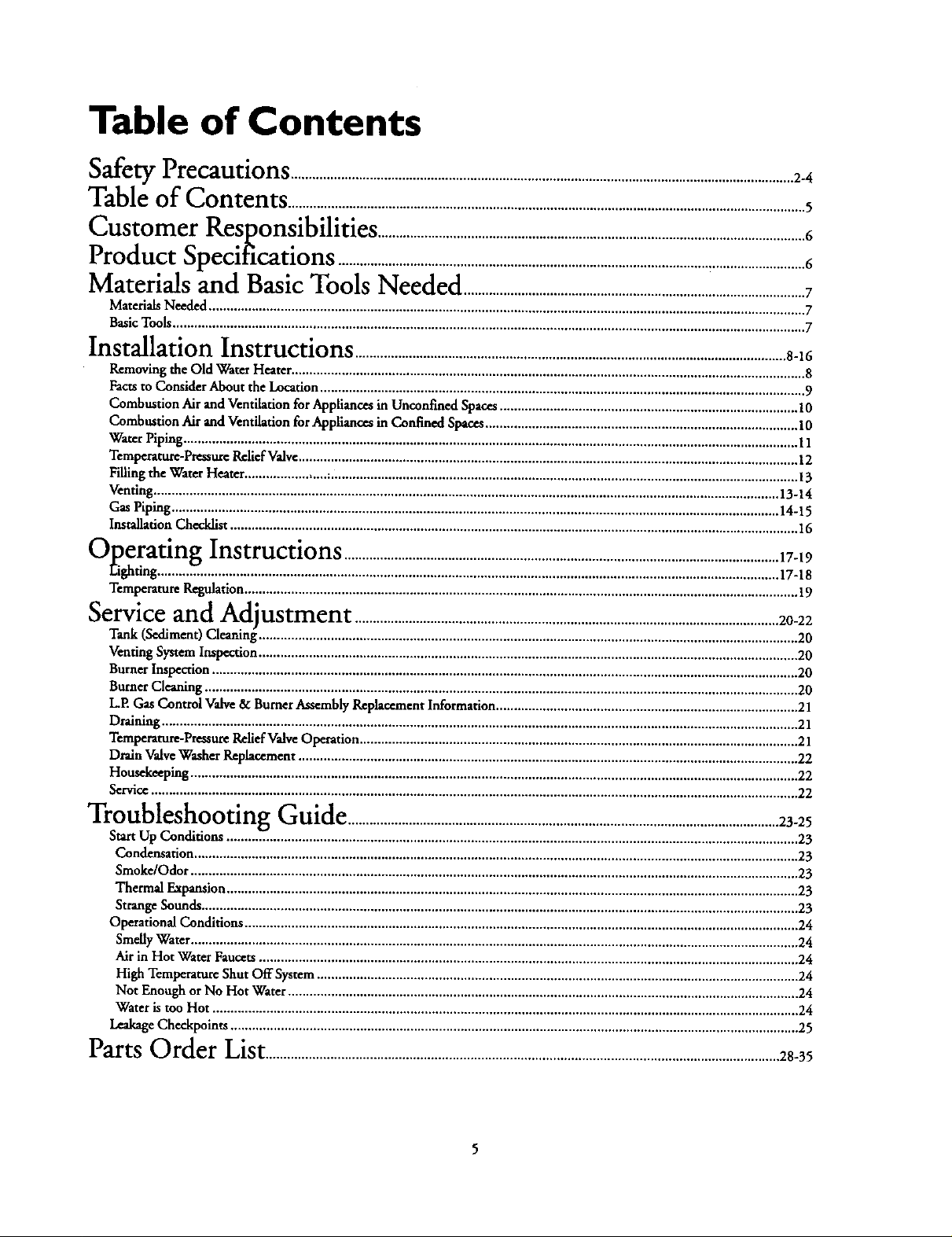
Table of Contents
Safety Precautions ............................................................................................................................................2_
Table of Contents ................................................................................................................................................5
Customer
Product
T'_ ol_14e
Kesponslbllltles .......................................................................................................................6
_ o/,b .
_pecmcauons ..................................................................................................................................6
Materials and Basic Tools Needed ....................................................................i..........................7
Materials Needed ...................................................................................................................................................................... 7
Basic Tools ................................................................................................................................................................................ 7
Installation Instructions ........................................................................................................................8-16
Removing the Old Water Heater ............................................................................................................................................... 8
Facts to Consider About the Location ....................................................................................................................................... 9
Combustion Air and Ventilation for Appliances in Unconfined Spaces ................................................................................... 10
Combustion Air and Ventilation for Appliances in Confined Spaces ....................................................................................... 10
Water Piping ........................................................................................................................................................................... 11
Temperature-Pressure Relief Valve ........................................................................................................................................... 12
Filling the Water Heater ....................... ;.................................................................................................................................. 13
Venting .............................................................................................................................................................................. 13-14
Gas Piping ......................................................................................................................................................................... 14-15
Installation Checklist .............................................................................................................................................................. 16
_""t)peratmgInstructions .........................................................................................................................17-19
Eighting .........Z. ................................................................................................................................................................ 17-18
Temperature Regulation .......................................................................................................................................................... 19
Serviceand
Tank (Sediment) Cleaning_....................................................................................................................... 20
Venting System Inspection ...................................................................................................................................................... 20
Burner Inspection ................................................................................................................................................................... 20
Burner Cleaning ..................................................................................................................................................................... 20
L.E Gas Control Valve & Burner Assembly Replacement Information .................................................................................... 21
Draining ................................................................................................................................................................................. 21
Temperature-Pressure Relief Valve Operat on .............................................................................. 21
Drain Valve Washer Replacement ........................................................................................................................................... 22
Housekeeping ......................................................................................................................................................................... 22
Service .................................................................................................................................................................................... 22
ACtlustment ......................................................................................................................20-22
"_ -" -"lroubleshootlng Guide ........................................................................................................................23-25
Start Up Conditions ...............................................................................................................................................................v 23
Condensation ........................................................................................................................................................................ 23
Smoke/Odor ......................................................................................................................................................................... 23
Thermal Expansion ............................................................................................................................................................... 23
Strange Sounds ...................................................................................................................................................................... 23
Operational Conditions .......................................................................................................................................................... 24
Smelly Water ......................................................................................................................................................................... 24
Air in Hot Water Faucets ...................................................................................................................................................... 24
High Temperature Shut Off System ...................................................................................................................................... 24
Not Enough or No Hot Water .............................................................................................................................................. 24
Water is too Hot ................................................................................................................................................................... 24
Leakage Checkpoints .............................................................................................................................................................. 25
Parts Order List...............................................................................................................................................28-35
Customer Responsibilities
Thank You _or purchasinga Sears water heater.
Properly installed and maintained, it should give you years of
trouble free service. If you should decide that you want the new
water heater professionally installed by Sears call the local Sears
Service Center or any Sears store. They will arrange for prompt,
quality installation by Sears authorized contractors.
Abbreviations Found In This Instruction Manual
I.A,S. - International Approval Services, A Division of CSA
A.N.S.I, - American National Standards Institute
N.EEA. - National FirePrevention Association
AWARNING
This gas-fired water heater is design certified by the
International Approval Services, A Division of CSA under
American National Standard/C$A Standard for Gas Water
Heaters AN$ Z21.10.1 • CSA 4.1 (latest edition). The
installation must conform with this manual, Local Codes
and with the latest edition of the National Fuel Gas Code,
ANSI Z223.1.
This publication is available from y_ur local government or
public library, gas company, or by writing NFPA.
Batterymarch Park, Quincy, MA 02269.
• Read the _Safety Precautions" section, pages 2 through 4 of
this,manual first and then the entire manual carefiflly. If you
dont follow the safety rules, the water heater will not operate
properly. It could cause DEATH, SERIOUS BODILY
INJURY AND/OR PROPERTY DAMAGE.
This manual contains instructions for the installation,opera-
tion, and maintenance of the gas-fired water heater. It also
contains warningsthrough out the manual that youmust read
and be awareoffAll warnings andall instructionsareessential
to the proper operation of the water heater and your safety.
Sincewe cannot put everythingon the first few pages,READ
THE ENTIRE MANUAL BEFORE ATTEMPTING TO
INSTALLOR OPERATETHEWATERHEATER.
• The installation must conform with the instructions in this
manual; gas company rules; and Local Codes, or in the
absenceofLocalCodes,with the latestedition ofthe National
FuelGas code, ANSI Z223.1, also referredto as NFPA 54.
This publication is available from your local governmentor
public library or gas company or by writing NFPA,
BattcrymarchPark,Quincy,MA02269.
• If a_er reading this manualyou haveany questions ordo not
understand any portion of the instructions, call the Sears
ServiceCenter.
• _y plan the placewhere you are going to put the water
heater. Correct combustion, vent action, and ventpipe instal-
htion are very importan_ in preventing dear from possible
cathon monoxidepoisoningand fires.
Examinethe locationto ensure the water heatercomplies with
the _Facrsto Consider About the Location"section in this
manual.
• For California installation this water heater must be braced,
anchored, or strapped to avoid failing or moving during an
earthquake. See instructionsfor correct installation proce-
dures.Instructions may be obtained from your local dealer,
wholesaler,public utilities or California Office of the State
Architect,400 P Street,Sacramento, CA 95814.
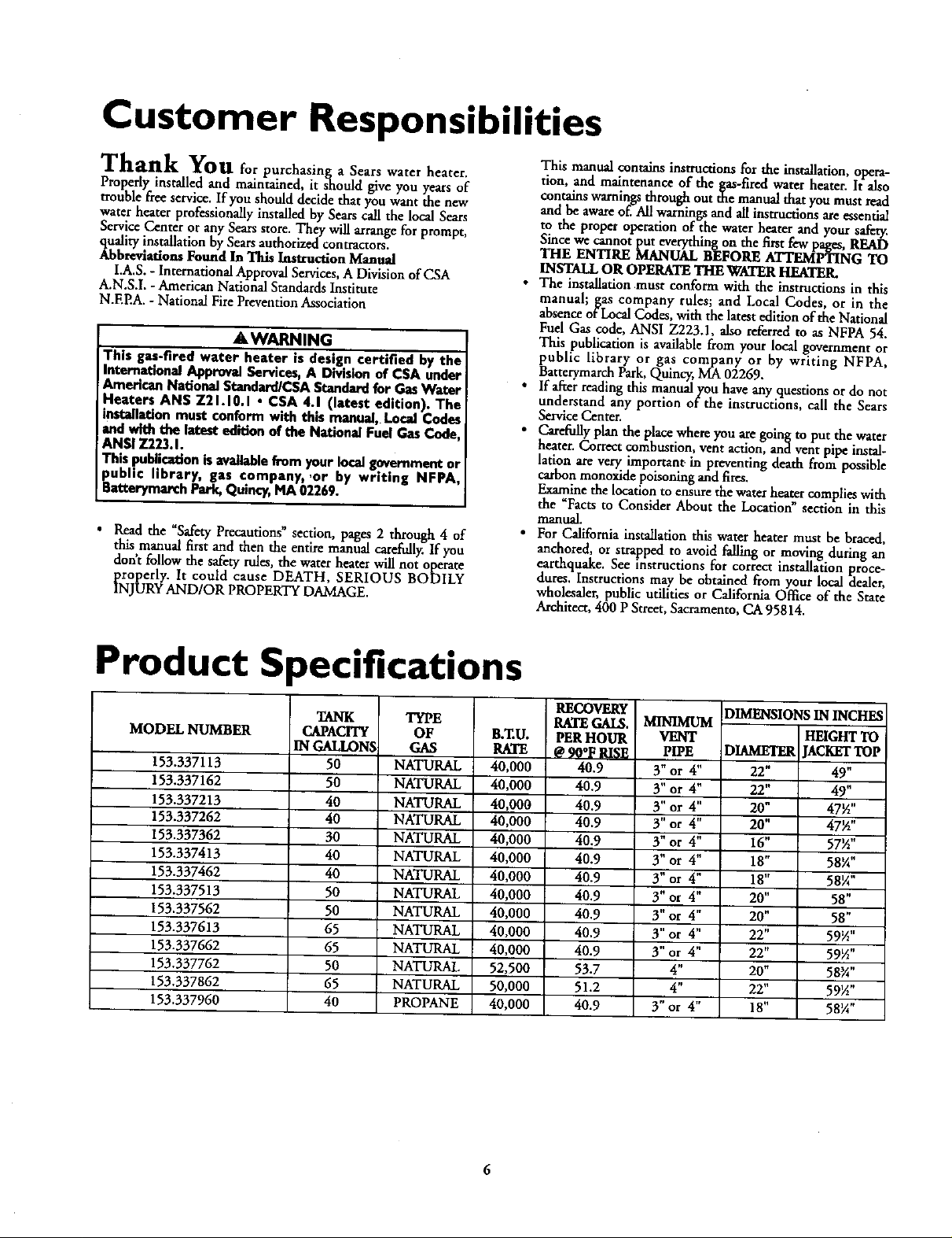
Product Specifications
MODEL NUMBER
153.337113
153.337162
153.337213
153.337262
153.337362
153.337413
153.337462
153.337513
153.337562
153.337613
153.337662
153.337762
153.337862
153.337960
TANK
CAPACITY
IN GALLONS
50
50
40
40
30
40
40
50
50
65
65
50
65
40
TYPE
OF
GAS
NATURAL
NATURAL
NATURAL
NATURAL
NATURAL
NATURAL
NATURAL
NATURAL
NATURAL
NATURAL
NATURAL
NATURAL
NATURAL
PROPANE
B,ZU.
RATE
40,000
40,000
40,000
40,000
40,000
40,000
40,000
40,000
40,000
40.000
40,000
52,500
50,000
40,000
RECOVEI_
RATE GAI&
PER HOUR
@9O°F8II;!_
40.9
40.9
40.9
40.9
40.9
40.9
40.9
40.9
40.9
40.9
40.9
53.7
51.2
40.9
MINIMUM
VENT
PIPE
3" or 4"
3"or 4"
3" or 4"
3"or 4"
3" or 4"
3" or 4"
3" or 4"
3" or 4"
3" or 4"
3"or 4"
3"or 4"
4"
4"
3"or 4"
DIMENSIONSIN INCHES
HEIGHTTO
)IAMETER JACKETTOP
22" 49"
22" 49"
20" 47½"
20" 47½"
16" 57½"
18" 58_A"
lg" 5glA"
20" 58"
20" 58"
22" 59½"
22" 59½"
20" 58_A"
22" 59½"
18" 58¼"

Materials and Basic Tools Needed
Materials Needed
To simplify the installation Sears has available the installation
_lsartsshown below.Youmay ormaynot needall of thesemateri-
, depending-onyour type of installation.
WATER HEATER HEAT
TRAPS HELP REDUCE
NEAT LOSS DUE TO
THERMAL SYPHONING
EXPANSION TANKS
FOR THERMAL
EXPANSION CONDI-
TIONS AVAILABLE IN
2 GALLON AND $
GALLON CAPACITY
THROUGN LOCAL
SEARS STORE OR
SERVICE CENTERS
VENT PIPE
WATER NEATER INSTAL-
LATION KIT WITH FLEXI-
BLE CONNECTORS FOR
314" OR 112" THREADED
OR COPPER PLUMBING
@
VENT ELBOW
FLEXIBLE WATER
HEATER GAS CON-
HECTOR WITN
FITTINGS
/ \
WATER HEATER STAND 24"x24"xl 8"
FOR USE WITH WATER HEATERS
INSTALLED IN RESIDENTIAL
GARAGES HAVING A DIAMETER 24"
OR LESS AND A RATED CAPACITY 7S
GALLONS OR LESS
DRAIN PANS AVAILABLE IN 20"
DIAMETER FOR WATER HEATERS
HAVING A DIAMETER 18" OR LESS
AND AVAILABLE IN 28" DIAMETER
FOR WATER HEATERS HAVING A
DIAMETER 26" OR LESS
Basic Tools
You may or may not need all of these tools, depending on your
type of installation. These tools can be purchased at your local
Scrags store,
• Pipe Wrenches (2) 14"
• Screwdriver
• Tin Snips
• 6 Foot Tape of Folding Rule
• Garden Hose
• Drill
• Pipe dope or Teflon Tape
GARDEN HOSE 6 FOOT TAPE
SLOT-HEAD SCREWDRIVER
PHILLIPS SCREWDRIVER
ROLL OF TEFLON TAPE
(USE ONLY ON WATER
CONNECTIONS)
PIPE DOPE (SQUEEZE TUBE)
USE FOR WATER AND
_AS CONNECTIONS)
PiPE
WRENCH
TIN SNIPS
ADDITIONAL TOOLS NEEDED
WHEN SWEAT SOLDERING
• Tubing Cutters or Hacksaw
• Propane Torch
• Sof_ Solder
• Solder Flux
• Emery Cloth
• Wire Brushes
HACKSAW
$14" WIRE BRUSH
C>--'"
ROLL OF LEAD FREE
ROLL OF EMERY
I/2" WIRE BRUSH
PROPANE
TORCH
SOFT SOLDER
CLOTH SOLDER FLUX TUBING
CUTTER
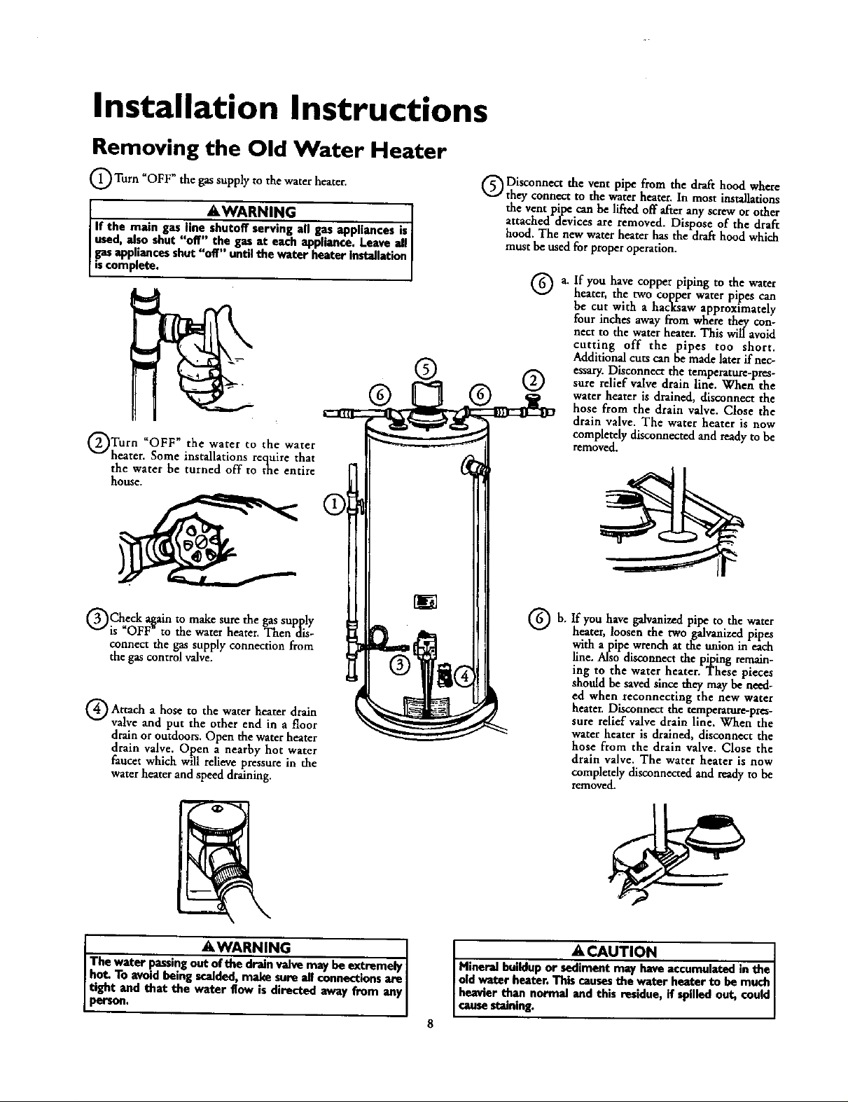
Installation Instructions
Removing the Old Water Heater
_OFF"the the heater,
Turn gassupply to water
l AWARN,N I
If the main gasline--all gasappliancesis
used, _lso shut'doff'"the gasat eachappliance. Leaveall
gasappliancesshut"off'" untilthe waterheaterinstallation
iscomplete.
@@ @ @
Turn _OFF" the water to the water
heater. Some installations require that
the water be turned off to the entire
house.
Disconnect the vent pipe from the drafthood where
they connect to the waterhearer.In most installations
the ventpipe canbe lifted off afterany screworother
attached devicesare removed, Dispose of the draft
hood. The new water heater has the drafthood which
mustbe usedfor properoperation.
a. If you have copper piping to the water
heater, the two copper water pipes can
be cut with a hacksaw approximately
four inches awayfrom where they con-
nect to the water heater. This will avoid
cutting off the pipes too short.
Additionalcuts can bemadelaterif nec-
essary.Disconnectthe temperature-pres-
sure relief valvedrainline. When the
water heater is drained,disconnect the
hose from the drain valve. Close the
drain valve. The water heater is now
completelydisconnectedandreadyto be
removed.
Check a_ainto make sure thegassupply
is OFF to the water heater. Then dis-
connect the gassupply connection from
the gascontrol valve.
a to water
Attach hose the heater drain
valve and put the other end in a floor
drainoroutdoors.Open the waterheater
drain valve. Open a nearby hot water
faucet which willrelievepressure in the
waterheater and speed draining.
I AWARNING
The water passingout--valve may be extremely
hot. To avoid being scalded,make sure all connectionsare I
i_.d that the water flow is directed away from any I
If you have galvanized pipe to the water
b,
heater, loosen the two galvanized pipes
with a pipe wrench at the anion in each
line. Also disconnect the piping remain-
lug to the water heater. These pieces
should be saved since they may be need-
ed when reconnecting the new water
heater. Disconnect the temperature-pres-
sure relief valve drain llne. When the
water heater is drained, disconnect the
hose from the drain valve. Close the
drain valve, The water heater is now
completely disconnected and ready to be
removed.
ACAUTION I
Mineral buildup or sediment may have accumulated in the
old water heater. Thiscausesthe water heater to be much
heavier than normal and this residue, if spilledout, could
causestaining.
Installation Instructions (cont'd)
Facts to Consider About the
Location
You should carefully choose an indoor location for the new
water heater, because the placement is a very important consid-
eration for the safety of the occupants in the building and for
the most economical use of the appliance. This water heater is
not for use in mobile homes or outdoor installation.
Whether replacing an old water heater or putting the water
heater in a new location, the following critical points must be
observed.
• The location selected should be indoors as close as practical
to the gas vent or chimney to which the water heater vent is
going to be connected, and as centralized with the water pip-
in._ system as possible. The water heater, as all water heaters
will eventually leak. Do not install without adequate
drainage provisions where water flow will cause damage.
&CAUTION
WATER HEATERS EVENTUALLY LEAK: Installation of the
water heater must be accomplisbedin sucha manner that if
the tank or anyconnectionsshouldleak,the flowof water will
notcausedan_ge to the structure.Wben suchIocatfonscan-
not be avoided, a soitalde drain panshouldbe installedunder
the water buater. Drain pansm_eavailableat your local Sears
store. Such a drain pan must be lootgreater than I _ inches
deep, have a minimum lengthand width of at least 2 inches
greater than the water heater dimensionsand must be piped
ito anadequatedrain.The panmust notrestrict combustionair
iBow.Under no circumstancesis the manufactureror Searsto
! be held liablefor any water damage in connectionwith this
!water heater.
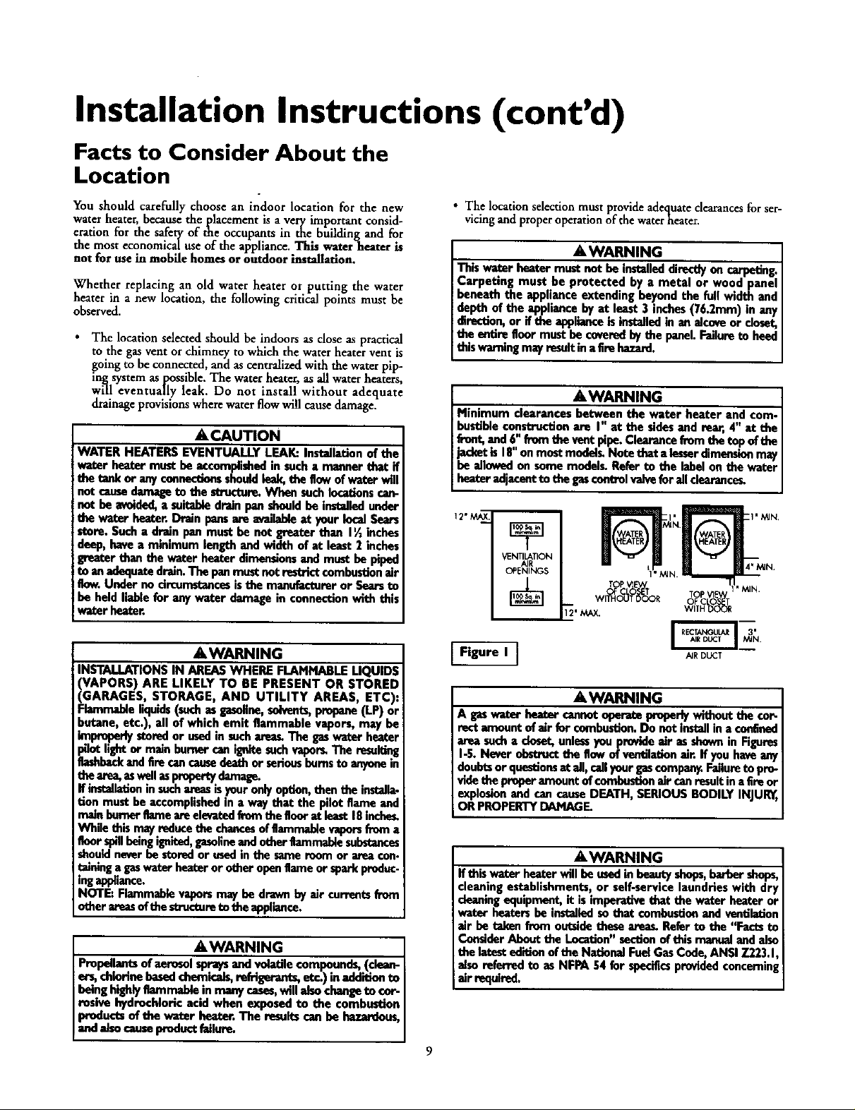
• The location selection must provide adequate clearances for ser-
vicing and proper operation of the waterheater.
AWARNING
This water heater must loot be installeddin_y on carpeting.
Carpeting must be protected by a metal or wood panel
beneath the appliance extending beyond the full width and
depth of the appliance by at least 3 inches (76.2mm) in any
direction,or if the applianceis installedin an alcoveor deset,
the entire floormust be coveredby the panel.Failureto heed
this warningmayresultin a firehazard.
AWARNING
Minimum clearances between the water heater and com-
bustibleconstruction are I" at the sidesand rear, 4" at the
front,and6" frem the vant pipe.Clearancefrom the top of the
jacketis I8" onmostmodelg Note that a lesserdimensionmay
be allowedon some modelg Refer to the labelon the water
heater adjacantto the gascnotrelvaivefor all dearance_
12"M__
VENTILATION
TOPP V_E'V,/
OF CLOSET TOP VI_
WITHOUT DOOR V_OIFT_ _d_
AWARNING
INSTALLATIONS IN AREAS WHERE FLAMMABLE LIQUIDS
VAPORS) ARE LIKELY TO BE PRESENT OR STORED
GARAGES, STORAGE, AND UTILITY AREAS ETC):
qammable iquids(suchasgasoline,solvents,propane(LP)or
butane, etc.), all of which emit flammable vapors, may be
improperlystoredor usedin suchare_ The gaswater heater
_ot light or main burner camignitesuch vaporLThe resul_ng
flashbackandfire cancausedeathorseriousbumsto anyonein
the area,eswellm pmportydamage.
If installat_ninsuchareasisyouronly option,then the installa-
tion must beaccomplishedin a way that the pilot flame and
mainbureor flameareeleva_._lfrem the goor at least18inches.
While this mayreducethe chancesof flammablevaporsfrom a
floor spillbeingigeited, gasolineand otherflammablesubstances
shouldneverbe storedorusedin the sameroom or area con.
talningagaswater heateror other openflameor sparkproduc.
ingappliance.
NOTE: Flammablevaporsmay be drawn by air currentsfrom
other areasof thestructureto the appliance.
AWARNING
Propellantsof aerosol spraysand vohLtilecompounds,(clean-
er_ chlorine basedchemicals,rofrigeran_, etc.) in addition to
beinghighlyflammable inmanycases,will also changeto cor-
rosive hydrochloric acid when exposed to the combustion
products of the wator beator. The resultscan be hazardous,
andalsocauseproductfailure.
Figure I ]
AIRDUCT
AWARNING
Ages wat_ bea_r cannotaperato preperlywithout the co_
rectamount of air for combustler_Do not installin a confined
area sucha closet,unle_ you provideair as shownin Figures
I-5. Never obstruct_ flow of ventilationair. If you haveany
doubtsor questionsat all, callyour gascompany.Failureto pro-
videthe proper amountof combustionair canresultin aEreor
explosionand cancauseDEATH, SERIOUS BODILY INJUI_,
OR PROPERTYDAMAGE.
AWARNING
If this water heater will be usedin beautyshops,barbershops,
cleaningestablishments, or self-service laundries with dry
cleaningequipment, it isimperative that the water heater or
water heatersbe installed sothat combustionand ventilation
air be taken from outsidethese areas, Refer to the "Facts to
ConsiderAbout the Location"sectionof this manualand also
the latestedition of the NationalFuel GasCode, ANSI 7.223.1,
alsoreferred to as NFPA 54 for specificsprovidedconcerning
air e_luired.
9
Installation Instructions (cont'd)
Combustion Air and Ventilation
for Appliances Located in
Unconfined Spaces
Unconfined Spac¢ is a space whosevolume is not less than 50
cubic feet per 1,000 Btu per hour of the aggregateinputrating
of all appliancesinstalhd in that space. Roomscommunicating
directlywith the space in which the appliances are installed,
through openings not furnished with doors, are considereda
partofthe unconfinedspace
In unconfined spacesin buildings, infiltrationmay be adequate
to provide air for combustion, ventilationand dilution of flue
gases.However,in buildings of tight construction (for example,
weatherstripping,heavilyinsulated, caulked, vaporbarrier,etc.),
additional air may need to be provided using the methods
describedin Combustion Air and Ventilation for Appliances
Locatedin Confined Spaces,b.
Combustion Air and Ventilation
for Appliances Located in
Confined Spaces
Confined Spacc is a spacewhose volumeis less than 50 cubic
feet per 1,000 Btu per hour of the aggregateinput ratingof all
appliancesinstalled inthat space.
a. ALL AIR FROM INSIDE BUILDINGS:
(SeePage9 Figure1,and Figure2 below)
The confined space shall be provided with two permanent
openingscommunicating directlywith an additional room(s)
of sufficient volume so that the combined volume of all
spacesmeets the criteria for an unconfined space. The total
input of all gas utilization equipment installed in the com-
bined spaceshallbe considered inmaking this determination.
Eachopeningshall have a minimum free area of one square
inch per 1,000 BTU per hour of the total inputratingofafi
gasutilization equipment in the confined space, but not less
than 100 squareinches. One openingshall commencewithin
12 inches of the top and onecommencing within 12 inches
of the bottom of the enclosure.
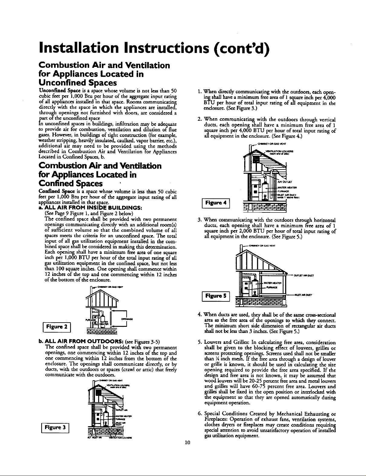
1.When direcdycommunicating with the outdoors,each open-
ing shallhaveaminimumflee areaof I squareinch per 4,000
BTU per hour of total input raring of all equipment in the
enclosure.(SeeFigure3.)
2. When communicatingwith the outdoors through vertical
ducts, each opening shall have a minimum free area of 1
sc!uareinch per 4,000 BTU per hour of total input ratingof
all equipment in the enclosure.(SeeFigure4.)
Figure 4 ]
3. When communicating with the outdoors through horizontal
ducts, each opening shall have a minimum free area of 1
square inch per 2,000 BTU per hour of total input rating of
all equipment in the endosure. (SeeFigure5.)
I Figure 2 ]
b. ALL AIR FROM OUTDOORS: (seeFigures3-5)
The confined space shall be provided with two permanent
openings,one commencing within 12 inchesof tee top and
one commencing within 12 inches from the bottom of the
enclosure. The openings shall communicate directly,or by
ducts,with the outdoorsor spaces (crawlorattic) that freely
communicatewiththe outdoors.
I Figure 3 ]
[el,-- ....
4.When ductsare used, they shallbe ofthe same cross-sectional
areaas the free area of the openingsto which they connect.
The minimum short side dimensionof rectangularair ducts
shallnot be lessthan 3 inches.(SeeFigure5.)
5. Louversand Grilles: In calculating free area, consideration
shall be given to the blocking effect of louvers, grillesor
screensprotecting openings.Screensused shall not be smaller
than ¼inch mesh.If the_ee area through a desi_ of louver
orgrilleis known, it should be used in calculating the size
opening recLuiredto provide the free area specified. If the
designand free area is not known, it may be assumed that
woodlouverswillbe20-25 percent freeareaand metallouvers
and grilleswill have 60-75 percent free area. Louversand
grillesshall be fixedin the open position orinterlocked with
the .equipment so.that they are openedautomaticallyduring
equipmentoperation.
6. Special Conditions Created by Mechanical Exhaustingor
Fireplaces:Operation of exhaust fans,ventilationsystems,
clothesdryersor fireplacesmay create conditions requiring
specialattention to avoid unsatisfactoryoperationof installed
gasutilizationequipment.
1o
_i " ....... Ii f I
Installation Instructions (cont'd)
Water Piping
AWARNING
HOVrERWATERCANSCALD:.Waterheatersareintendedto
producehot_ Waterheatedto a temperaturewhichwill
satisfyclotheswashing,dishwashing,andothersanitizingneeds
_n sealdandpmnanentlyInjureyouuponcontoc_Somepe_
piem_emore Wadyto be pem_nen_ injured byhot w_er _
others.TheseI_fude t_ elde_ ddldren, the k_irm,orp_sk_
ly/mentallyhandicapped.Ifanyoneusinghot waterinyourhome
Etsintooneofthese gruupsor ifthere isa localcadeorstatolaw
requiringa certaintompeeature _ atthehot watortap,then
foumusttakespecialprecaudom.Inadditionto usingthelowest
)ossiblettmperatum set,rigthatsatisEesyourhotwaterneeds,
_meanssuchasa mixingvalve,shouldbeusedatthehotwater
tapsusedbythesepeopleorot the woterheater.Mixingvalves
aruwallableatplumbingsupl_yorhan_r_xestoreLFollowman-
ufacturersinstructionsfor installationof thevalves.Before
changingthe factory settingon the thermostat,read the
"TemperatureRegulation"sectioninthismanual.
This waterheater shallnot be connected to any heating systems
or component(s) used with a non-potable water heating
appliance.
If a water heater is installed in a closed water supply system;
such as one having a back-flow preventer, check valve, water
meterwith a check valve,etc.., in the cold water supply; means
shall be provided to control thermal expansion. Contact the
local utility or localSearsServiceCenter on how to control this
situation.
NOTE: Toprotect against untimely corrosion of hot and
cold water fitthags,it is steon_iy recommended that all-elec-
tric unions or couplings be mstelled on this water heater
when connected to copperpipe.
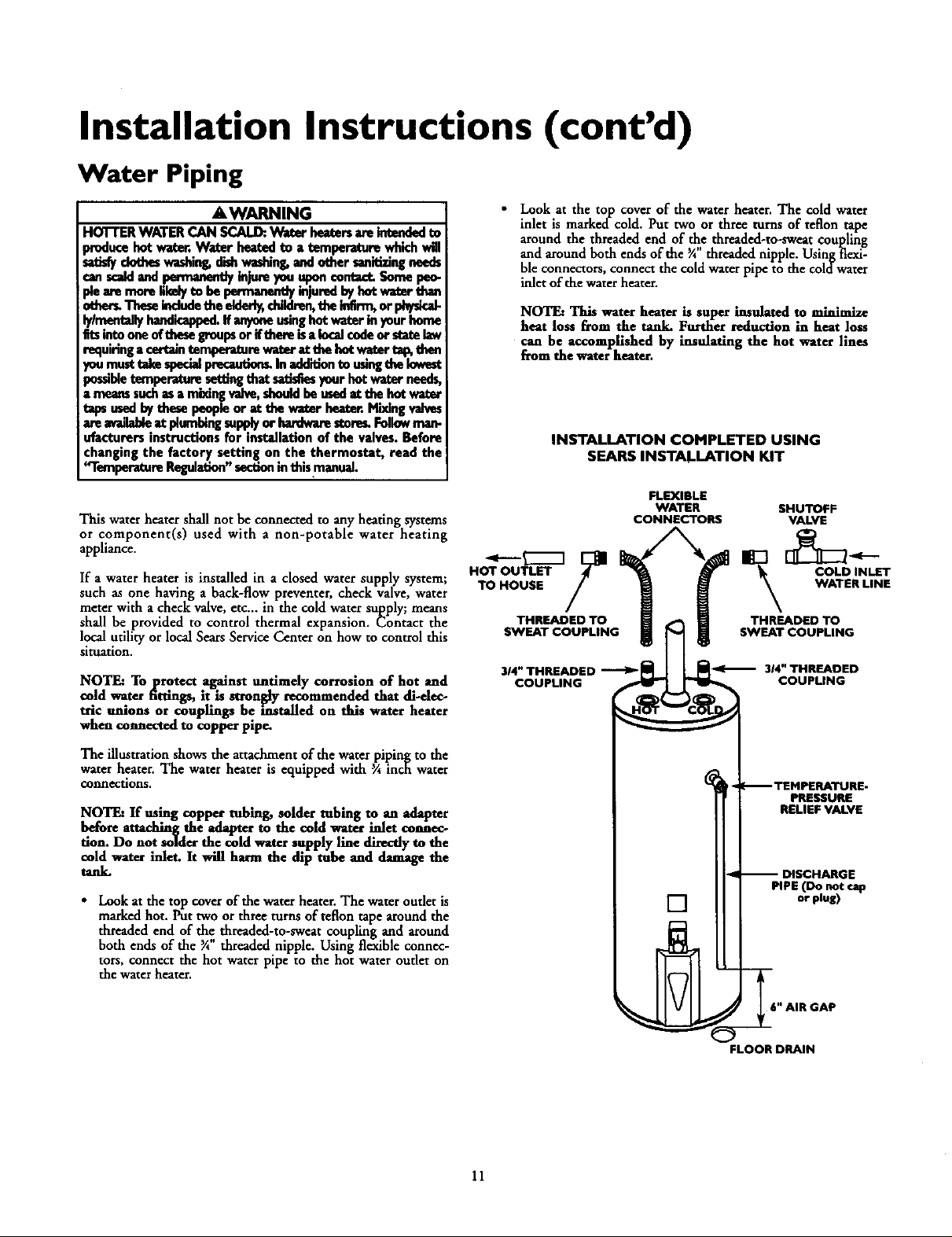
• Look at the top cover of the waterheater. The cold water
inlet is markedcold. Put two or three turnsof teflon tape
around the threaded end of _e threaded-to-sweat coupling
and around both ends of the ¾ threaded nipple. Usingflexi-
ble connectors,connect the cold waterpipe to the coldwater
inlet of the waterheater.
NOTE: This water heater is super insulated to minimize
heat loss from the tank. Further reduction in heat loss
can be accomplished by insulating the hot water lines
from the water heater.
INSTALLATION COMPLETED USING
SEARS INSTALLATION KIT
FLEXIBLE
WATER SHUTOFF
CONNECTORS VALVE
HOT OUTLET COLD INLET
TO HOUSE WATER LINE
THREADED TO _ THREADED TO
314"THREADED _ _ 314"THREADED
COUPLING COUPLING
SWEAT COUPLING_ SWEAT COUPLING
The illustration shows the attachment of the water piping to the
water heater. The water heater is equipped with 3Ainch water
connections.
NOTE: If using copper tubing, solder tubing to an adapter
before auaching the adapter to the cold water inlet connec-
tion. Do not solder the cold water supply line directlyto the
cold water inlet. It will harm the dip tube and damage the
tank.
• Look at the top coverof the waterheater.The water oudet is
markedhot. Puttwo orthree turns of teflon tape around the
threaded end of the threaded-to-sweat coupling a-,xdaround
both ends of the _A"threaded nipple. Using flexible connec-
tors, connect the hot waterpipe to the hot water outlet on
the waterheater.
11
_ TEMPERATURE-
PRESSURE
RELIEF VALVE
-- DISCHARGE
PIPE (Do not cap
[]
,_ _6" AIR GAP
FLOOR DRAIN
or plug)
 Loading...