

Owner's
Manual
FOR POTABLEWATER
HEATING ONLY
NOT SUITABLEFOR
SPACEHEATING
NOT FOR USE IN
MOBILE HOMES
COMMERCIAL
GAS WATER HEATER
Hodel No.
153.337000 I00 Gal.
153.337070 73 GaL
• Safety Instructions
• Installation
• Operation
• Care and Maintenance
• Troubleshooting
• Parts List
For Your Safety
AN ODORANT IS ADDED TO THE GAS USED BY THIS
WATER HEATER
"WARNING: If the information in these instructions are not fol-
.lowed exactly, a fire or explosion may result, causing property
damage, personal ,nlury or death.
-Do not store or use gasoline or other flammable vapors and liquids
in the vicinity of this or any other appliance.
--WHAT TO DO IF YOU SMELL GAS
• Do not try to light any appliance.
• Do not touch any electrical switch; do not use any phone in your
building.
• Immediately call your gas supplier from a neighbor's phone.
Follow the gas supplier's]nstructions.
• If you can not reach your gassupplier, call the fire department.
-Installat!on and service must be performed l)y a qualified installer,
service agency or the gassupplier.
Caution:
Read and Follow
All Safety Rules and
Operating Instructions
Before First Use of
This Product.
Save this Manual for Future Reference.
Sears, Roebuck and Co., Hofl'man Estates, IL 60179 U.S.A.
• . AWARNING .
Improper installation, adlustment , alteration, service or maantenance can
cause DEATH, SERIOUS BODILY INJURY, OR PROPERTY DAMAGE. Refer to
this manual for assistanceor consult the local Sears Service Center or gas util-
ty for further information.
Flammable vapors may be AWARNING
structure to this appliance.
READ THE GENERAL SAFETY SECTION BEGINNING ON INSIDE COVER
AND THEN THIS ENTIRE MANUAL BEFORE INSTALLING OR OPERAT-
ING THIS WATER HEATER•
drawn by air currents from other areas of the
AWARNING
Safety Precautions
_,WARNING I
er installation, adjustment, alteration, service or I
nance can cause DEATH, SERIOUS BODILY I
OR PROPERTY DAMAGE. Refer to this manu- I
ssistance or consult your local Sears Service[
for further information. J
&WARNING
WATER HEATERS EQUIPPED FOR ONE TYPE GAS
ONLY: This water heater is equipped for one type gas
only. Check the model rating plate near the gascontrol
valve for the correct gas. DO NOT USE THIS WATER
HEATER WITH ANY GAS OTHER THAN THE ONE
SHOWN ON THE MODEL RATING PLATE. Failure to
usethe correctgascan causeproblemswhichcan resultin
DEATH, SERIOUS BODILY INJURY, OR PROPERTY
DAMAGE. If you have any questions or doubts consult
yourgassupplieror localutility.
A,WARNING
INSTALLATIONS IN AREAS WHERE FLAMMABLE LIQ-
UIDS (VAPORS) ARE LIKELY TO BE PRESENT OR
STORED (GARAGES, STORAGE, AND UTILITY AREAS
ETC): Flammable liquids (such as gasoline, solvents
propane(LP) or butane, etc.), all ofwhichemit flammabk
vapors,may be improperly stored or used in such areas.
The gaswater heater pilot light or main burner can ignite
suchvapors. The resulting flashbackand fire can cause
death or serious burns to anyonein the area, as well as
property damage.
If installation in such areas isyour only option, then the
installationmust be accomplishedin a way that the pilot
flame and main burner flame are elevated from the floor
at least 18 inches.While this may reduce the chancesof
flammable vaporsfrom a floor spillbeingignited, gasoline
and other flammable substancesshouldneverbe stored or
used in the same room or area containing a gas water
heater or other openflame or sparkproducingappliance.
NOTE: Flammable vapors may be drawn by air currents
from other areasofthe structure to the appliance.
AWARNING
If this water heater will be used in beauty shops,barber
shops,cleaning establishments, or self-servicelaundries
with dry cleaning equipment, it is imperative that the
water heater or water heaters be installed so that com.
hustion and ventilation air be taken from outside these
areas. Refer to the "Locating The New Water Heater"
section of this manual and also the latest edition of the
National Fuel Gas Code, ANSI Z223.1, also referred to as
NFPA 54for specifics providedconcerningairrequired.
_WARNING
A fire can start if combustiblemater_l.s suchas clothing,I
cleaningmaterials,or flammable liqu,dsare placedagainst
or nextto the water heater.
A,WARNING
At the time of manufacture this water heater was pro-
vided with a combination temperature-pressures relief
valvecertified by a nationally recognized testing labora-
tory that maintains periodic inspection of productionof
listed equipment or materials, as meeting the require-
ments for Relief Valves and Automatic Gas Shutoff
Devices for Hot Water Supply Systems, and the latest
edition of ANSI Z21.22 and the code requirements of
ASME. If replaced, the valve must meet the require-
ments of local codes, but not less than a combination
temperature and pressurerelief valve certified as meet-
ing the requirements for Relief Valves and Automatic
Gas Shutoff Devices for Hot Water Supply Systems,
ANSI Z21.22 by a nationally recognized testing laborato-
ry that maintains periodic inspection of production of
listed equipment or materials.
The valvemust be marked with a maximum set pressure
not to exceed the marked hydrostatic working pressure
of the water heater (150 Ibs./sq. in.) and a discharge
capacity not less than the water heater input rate as
shown on the model rating plate. (Electric heaters .
watts divided by 1000x 3415 equal BTU/Hr. rate.)
Your local jurisdictional authority, while mandating the
use of a temperature-pressure relief valve complying
with ANSI Z21.22 and ASME, may require a valve model
different from the one furnishedwith the water heater.
Compliance with suchlocal requirements must be satis-
fied bythe installer or end user of the water heater with
a locally prescribed temperature-prossure relief valve
installedin thedesignated openingin the water heater in
_lace of the factory furnishedvalve.
or safe operation of the water heater, the rehef valve
must not be removed from it's designated opening or
plugged.
The temperature-pressure relief valve must be installed
directly intothe fitting of the water heater designatedfor
the relief valve. Position the valvedownward and provide
tubingsothat any dischargewill exit only within 6 inches
above, or at any distance below the structural floor. Be
certain that no contact is made with any live electrical
part. The discharge opening must not be blocked or
reduced in size under any circumstances. Excessive
length,over 30 feet, or useof more than four elbowscan
cause restriction and reduce the discharge capacity of
the valve.
No valve or other obstruction is to be placed between
the relief valve and the tank. Do not connect tubing
directly to dischargedrain unlessa 6" air gap isprovided.
To prevent bodilyinjury, hazard to life, or property dam.
age, the relief valve must be allowed to dischargewater
in quantities should circumstances demand. If the dis-
chargepipeis not connected to a drain or other suitable
means, the water flow may causeproperty damage.
The DischargePipe:
Must not be smaller in size than the outlet pipe sizeof
the valve, or have any reducing couplings or other
restrictions.
Must not be pluggedor blocked.
Must be ofmaterial listed for hot water distribution.
Must be installed so as to allow complete drainage of
both the temperature-pressure relief valve, and the
dischargepipe.
• Mustterminate at an adequatedrain.
• Must not have any valve between the relief valve and
tank.
Safety Precautions
a,WARNING
A gas water heater cannot operate properlywithout the
correct amount of air for combustion.Do not install in a
confined area such a closet, unless you provide air as
shownin the "Locating The New Water Heater" section.
Never obstruct the flow of ventilation air. If youhaveany
doubts or questionsat all, call your gascompany.Failure
to providethe proper amount ofcombustionair can result
in a fire or explosion and can cause DEATH, SERIOUS
BODILY INJURY,OR PROPERTY DAMAGE.
_,WARNING
HOTTER WATER CAN SCALD: Water heaters are
intended to produce hot water. Water heated to a tem-
perature which will satisfyclotheswashing,dishwashing,
and other sanitizing needs can scald and permanently
injure you upon contact. Some people are more likely to
be permanently injured by hot water than others. These
includethe elderly,children,the infirm, or physically/men-
tally handicapped.If anyone usinghot water in your home
fits into one of these groupsor if there is a localcode or
state law requiring a certain temperature water at the hot
water tap, then you must take specialprecautions.In addi-
tion to usingthe lowestpossibletemperature settingthat
satisfiesyour hot water needs, a means such asa mixing
valve,shouldbe usedat the hot water taps usedby these
people or at the water heater. Mixing valvesare available
at plumbing supplyor hardware stores. Follow manufac-
turers instructions for installation of the valves. Before
changingthe factory setting on the thermostat, read the
"Temperature Regulation"sectionin this manual.
_,WARNING
Soot build-up indicates a problem that requires correc-
tion before further use. Turn "off" gas to water heater
and leave"off" until repairs are made, becausefailure to
correct the cause of the sooting can result in a fire or
explosion causing DEATH, SERIOUS BODILY INJURY,
OR PROPERTY DAMAGE.
_E,WARNING
This water heater must not be installed directly on car-
peting.Carpeting must be protected by a metal or wood
panel beneath the appliance extending beyond the full
width and depth of the appliance by at least 3 inches
(76.2mm) in any direction, or ifthe appliance isinstalled
in an alcoveor closet,the entire floor must be covered by
the panel. Failure to heed this warning may result in a
fire hazard.
_,WARNING
VENT DAMPERS - Any vent damper,whether it isoperat-
ed thermally or otherwise must be removed if its use
inhibitsproperdraftingofthe water heater.
Thermally Operated Vent Dampers: Gas-fired water
heaters havingthermal efficiency in excessof 80% may
producea relatively low flue gastemperature. Suchtem-
peraturesmay not be highenoughto properly open ther-
mally operatedvent dampers. Thiswould causespillageof
flue gasesand maycausecarbonmonoxidepoisoning.
Vent dampersmust bear evidenceof certification ascom-
plying with the latest edition of American National
Standard ANSI Z21.68 (ANSI Z21.66 & 67, respectively,
cover electrically and mechanically actuated vent
dampers). Before installationof any vent damper, consult
your local Sears Service Center or the gasutility for fur-
ther information.
AWARNING
• The appliance and its individualshutoffvalvemust bedis-
connectedfrom the gassupplypipingsystemduring any
pressuretesting of the gassystem at test pressuresin
excessof I/2 poundper squareinch(3.5kPa).
• The appliance must be isolatedfrom the gassupplypip-
ing systemby closingits individualmanual shutoff valve
during any pressuretesting of the gassupplypipingsys-
tem at test pressuresequal or lessthan I/2 pound per
squareinch(3.5kPa).
a, WARNING
BEFORE LIGHTING [PROPANE (L.P.) GAS WATER
HEATERS]: Propane (L.P.)gas isheavier than air. Should
there be a leak in the system, the gaswill settle near the
ground. Basements, crawl spaces, skirted areas under
mobile homes (even when ventilated), closetsand areas
belowgroundlevelwill serveas pocketsfor the accumula-
tion of this gas. Before attempting to light or relight the
water heater's pilot or turning on a nearby electrical light
switch, be absolutely surethere isno accumulated gas in
the are_ Searchfor odor ofgasbysniffingat groundlevel
in the vicinity of the appliance. If odor isdetected, follow
stepsindicatedat "For Your Safety" on the cover pageof
this manualthen leavethe premises.
AWARNING
Chemical vapor corrosion of the flue and vent system
may occur if air for combustioncontainscertain chemical
vapors.Spraycanpropellants,cleaningsolvents,refrigera-
tor and air conditioner refrigerants, swimming pool
chemicals, calcium and sodium chloride, waxes, bleach,
and processchemicals are typical compoundswhich are
potentiallycorrosive.
Obstructed or deteriorated vent systemsmay present
serious healthriskor asphyxiation.
3
AWARNING a
Safety Precautions continued on page 4
Safety Precautions
•,WARNING I
The water heater with draft hood installedmustbe prop-I
erly vented to a chimney which terminates outdoors. I
Never operate the water heater unlessit isvented to the I
outdoors and has adequate air supplyto avoid risks of
improper operat on,expos on or asphyxat on.
AWARNING
Minimum clearancesbetween the water heater and com-
bustibleconstructionare I" at the sidesand rear, 4" at the
front,and6" fromtheventpipe.Clearancefromthe top ofthe
jacketis 18".Referto the labelonthe water heateradjacentto
[the gascontrovaiveforai cearances.
I AWARNING I
Do not usethis appli_of it has been underI
water. Immediately call a Sears Service Technician to I
inspectthe applianceand to replace the gascontrol or any I
part ofthe burner systemwhichhas been under water. I
AWARNING
HYDROGEN GAS:Hydrogengascan be producedin a hot
water system that has not been used for a long period of
time (generally two weeks or more). Hydrogen gas is
extremely flammable and explosive.To prevent the possi-
bility of injuryunder these conditions,we recommend the
hot water faucet he opened for several minutes at the
kitchen sink before any electrical appliances which are
connected to the hot water system are used (such as a
dishwasheror washing machine). If hydrogengasis pre-
sent, there will probablybe an unusualsoundsimilarto air
escaping through the pipe as the hot water faucet is
opened. There must be no smoking or open flame near
the faucetat the time it isopen.
• ,CAUTION
WATER HEATERS EVENTUALLY LEAK: Installation of
the water heater must be accomplishedin such a manner
that iftbe tank or any connectionsshouldleak, the flow of
water will not causedamage to the structure. When such
locations cannot be avoided, a suitable drain pan should
be installedunder the water heater. Drain pansare avail-
able at your localSears store. Such a drain pan must be
not greater than 1I/2 inches deep, have a minimum
length and width of at least 2 inches greater than the
water heater dimensions and must be piped to an ade-
quete drain. The pan must not restrict combustion air
flow. Under no circumstances is the manufacturer or
Sears to be held liable for any water damage in connec-
tion with thiswater heater.
AWARNING
INSULATING JACKETS: When installing an external
water heater insulationjacketon a gaswater heater:
• DO NOT coverthe temperature-pressure relief vaive.
• DO NOT put insulationover any part of the top of the
gaswater heater.
• DO NOT put insulationover the gascontrol valveor gas
control valve/burner cover,or any accessareas to the
burner.
• DO NOT let insulationaround the gaswater heater to
get within 8 inches of the floor (air must get to the
burner).
• DO NOT cover or remove operating instructions, and
safetyrelated warninglabelsand mateHais affixedto the
water heater.
Failureto heedthis will result in the possibilityof a fire or
explosion.
4
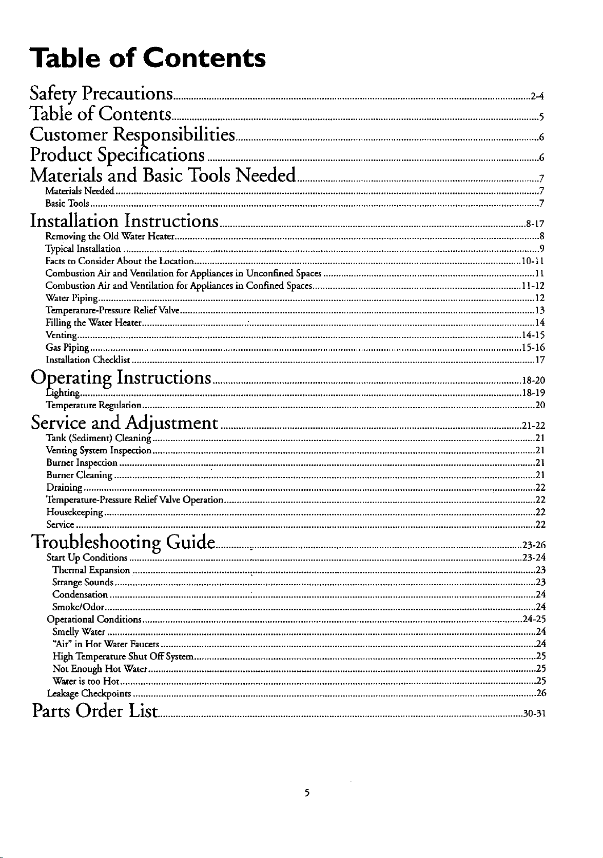
Table of Contents
oc___oarervPrecautions ............................................................................................................................................2-4
Table of Contents ................................................................................................................................................5
Customer
Responsibilities .......................................................................................................................6
Product Specifications ..................................................................................................................................6
Materials and BasicTools Needed ...............................................................................................7
Materials Needed ...................................................................................................................................................................... 7
BasicTools ................................................................................................................................................................................ 7
Installation Instructions ........................................................................................................................8-17
Removing the Old Water Heater ............................................................................................................................................... 8
Typical Installation ................................................................................................................................................................... 9
Facts to Consider About the Location ................................................................................................................................ 10-t 1
Combustion Air and Ventilation for Appliances in Unconfined Spaces ................................................................................... 11
Combustion Air and Ventilation for Appliances in Confined Spaces.................................................................................. 11-12
Water Piping ........................................................................................................................................................................... 12
Temperamre-Pressure Relief Valve........................................................................................................................................... 13
Filling the Water Heater ......................................... :................................................................................................................ 14
Venting .............................................................................................................................................................................. 14-15
Gas Piping ......................................................................................................................................................................... 15-16
Installation Checklist .............................................................................................................................................................. 17
_-:-vveratm_Instructions ......................................................................................................................... 18-20
_ V
Fighting............................................................................................................................................................................. 18-19
Temperature Regulation.......................................................................................................................................................... 20
Service and Ad iustment ...................................................................................................................... 21-22
Tank (Sediment) Cleaning ...................................................................................................................................................... 21
Venting System Inspection ...................................................................................................................................................... 21
Burner Inspection .................................... :.............................................................................................................................. 21
Burner Cleaning ..................................................................................................................................................................... 21
Draining ................................................................................................................................................................................. 22
Temperature-Pressure ReliefValve Operation .......................................................................................................................... 22
Housekeeping ......................................................................................................................................................................... 22
Service .................................................................................................................................................................................... 22
Troubleshooting Guide ..............:.........................................................................................................23-26
Start Up Conditions .......................................................................................................................................................... 23-24
Thermal Expansion .............................................. :............................................................................................................... 23
Strange Sounds ..................................................................................................................................................................... 23
Condensation ....................................................... :............................................................................................................... 24
Smoke/Odor ......................................................................................................................................................................... 24
Operational Conditions ..................................................................................................................................................... 24-25
Smelly Water ........................................................................................................................................................................ 24
"Air" in Hot Water Faucets................................................................................................................................................... 24
High Temperature Shut OffSystem ...................................................................................................................................... 25
Not Enough Hot Water ........................................................................................................................................................ 25
Water is too Hot ................................................................................................................................................................... 25
Leakage Checkpoints .............................................................................................................................................................. 26
Parts Order List...............................................................................................................................................30-3t
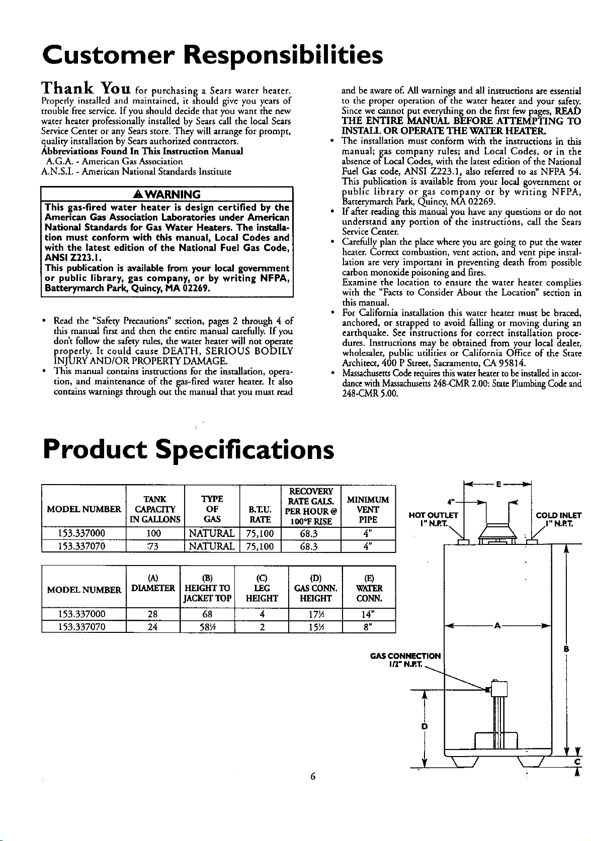
Customer Responsibilities
Thank You for purchasing a Sears water heater•
Properly installed and maintained, it should give you years of
trouble free service. If you should decide that you want the new
water hearer professionally installed by Sears call the local Sears
Service Center or any Sears store. They will arrange for prompt,
quality installation by Searsauthorized contractors.
Abbreviations Found In This Instruction Manual
A.G.A. - American Gas Association
A.N.S.I. - American National Standards Institute
AWARNING
This gas-fired water heater is design certified by the
American Gas AssociationLaboratories under American
National Standardsfor Gas Water Heaters. The installa-
tion must conform with this manual, Local Codes and
with the latest edition of the National Fuel Gas Code
ANSI Z223. I.
This publication is available from your local governmen_
or public library, gas company, or by writing NFPA,
Batterymarch Park, Quincy,MA 02269.
• Read the "Safety Precautions" section, pages 2 through 4 of
this manual first and then the entire manual carefully. If you
don't follow the safety rules, the water heater will not operate
properly. It could cause DEATH, SERIOUS BODILY
INJURY AND/OR PROPERTY DAMAGE.
• This manual contains instructions for the installation, opera-
tion, and maintenance of the gas-fired water heater. It also
contains warnings through out the manual that you must read
and be aware of. All warnings and all instructions are essential
to the proper operation of the water heater and your safety.
Since we cannot put everything on the first few pages, READ
THE ENTIRE MANUAL BEFORE ATTEMPTING TO
INSTALL OR OPERATE THE WATER HEATER.
• The installation must conform with the instructions in this
manual; gas company rules; and Local Codes, or in the
absence of Local Codes, with the latest edition of the National
Fuel Gas code, ANSI Z223.1, also referred to as NFPA 54.
This publication is available from your local government or
public library or gas company or by writing NFPA,
Batterymarch Park, Quincy, MA 02269.
• If after reading this manualyou have any questions or do not
understand any portion of the instructions, call the Sears
Service Center.
• Carefully plan the place where you are going to put the water
heater. Correct combustion, vent action, and vent pipe instal-
lation are very important in preventing death from possible
carbon monoxide poisoning and fires.
Examine the location to ensure the water heater complies
with the "Facts to Consider About the LocatioN' section in
this manual.
• For California installation this water heater must be braced,
anchored, or strapped to avoid falling or moving during an
earthquake. See instructions for correct installation proce-
dures. Instructions may be obtained from your local dealer,
wholesaler, public utilities or California Office of the State
Architect, 400 P Street, Sacramento, CA 95814.
• Massachusetts Code requires this water heater to be installed in accor-
dance with Massachusetts248-CMR 2.00: State Plumbing Code and
248-CMR 5.00.
Product Specifications
RECOVERY
RATEGALS.
PERHOUR@
100*FRISE
68.3
68.3
MINIMUM
VENT
PIPE
4"
4"
GAS CONNECTION
MODELNUMBER
153.337000
153.337070
TANK
CAPACITY
IN GALLONS
100
73
TYPE
OF B.T.U.
GAS RATE
NATURAL 75,100
NATURAL 75,100
(A) (B) (¢1 (D) (E)
MODEL NUMBER DIAMETER HEIGHTTO LEG GASCONN. WATER
JACKETTOP HEIGHT HEIGHT CONN.
153.337000 28 68 4 17_ 14"
153.337070 24 58_ 2 15_ 8"
I_"N.P._
I" N.RT.
C_/_LDINLET
A
B
D
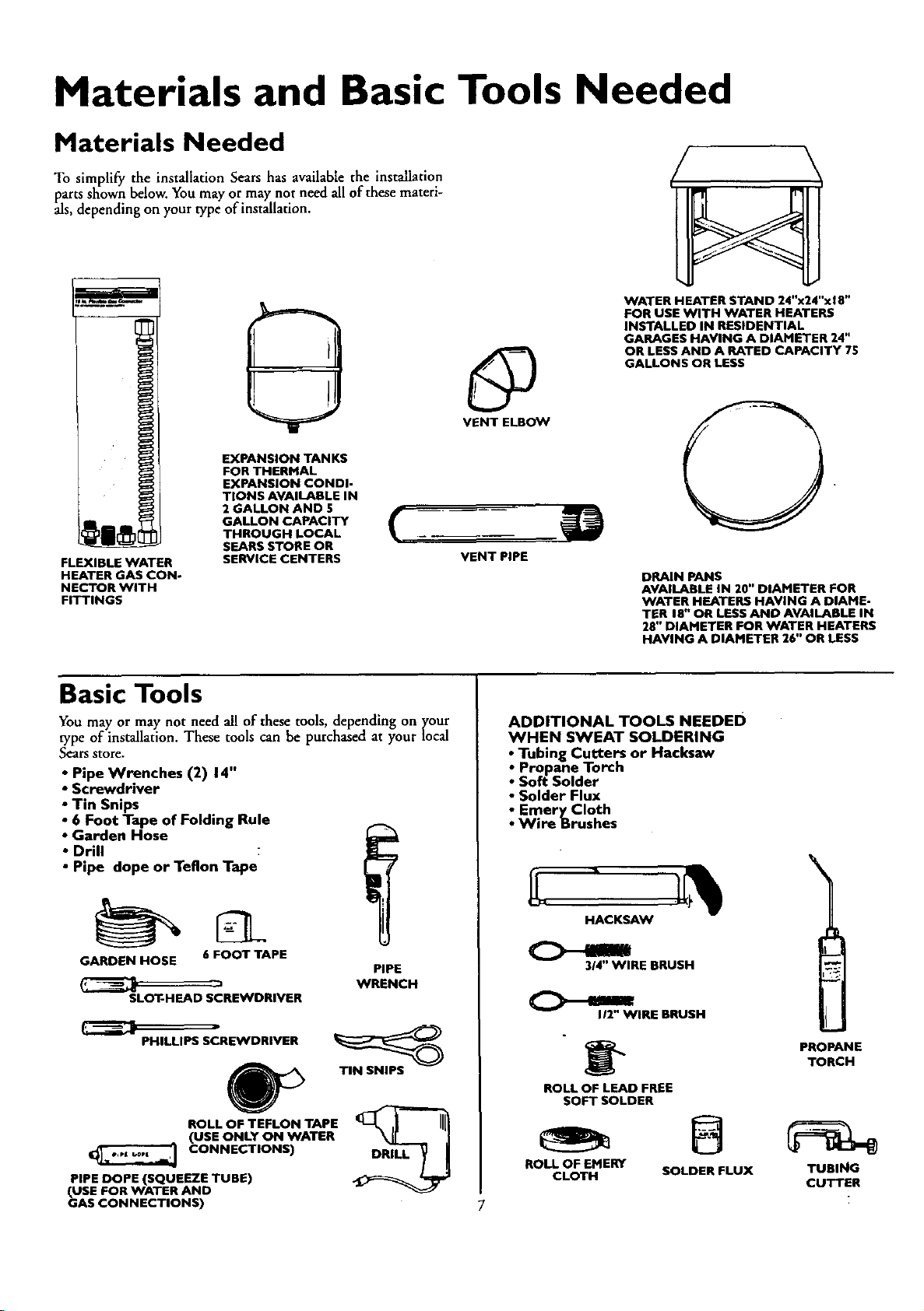
Materials and Basic Tools Needed
Materials Needed
To simplify the installation Sears has available the installation
parts shown below. You may or may not need all of these materi-
als, depending on your type of installation.
WATER HEATER STAND 24"x24"x18"
FOR USE WITH WATER HEATERS
INSTALLED IN RESIDENTIAL
GARAGES HAVING A DIAMETER 24"
OR LESS AND A RATED CAPACITY 75
GALLONS OR LESS
@
VENT ELBOW
EXPANSION TANKS
FOR THERMAL
EXPANSION CONDI-
TIONS AVAILABLE IN
2 GALLON AND 5
GALLON CAPACITY
THROUGH LOCAL
FLEXIBLE WATER
HEATER GAS CON-
NECTOR WITH
FITTINGS
SEARS STORE OR
SERVICE CENTERS
VENT PIPE
DRAIN PANS
AVAILABLE IN 20" DIAMETER FOR
WATER HEATERS HAVING A DIAME-
TER 18" OR LESS AND AVAILABLE IN
28" DIAMETER FOR WATER HEATERS
HAVING A DIAMETER 26" OR LESS
Basic Tools
You may or may not need all of these tools, depending on ycour
type of installation. These tools can be purchased at your local
Sears store.
• Pipe Wrenches (2) 14"
• Screwdriver
• Tin Snips
• 6 Foot Tape of Folding Rule
• Garden Hose
• Drill
• Pipe dope or Teflon Tape
GARDEN HOSE 6 FOOT TAPE
r7
SLOT-HEAD SCREWDRIVER
m
PHILLIPS SCREWDRIVER
ROLL OF TEFLON TAPE
(USE ONLY ON WATER
CONNECTIONS)
PIPE DOPE (SQUEEZE TUBE)
(USE FOR WATER AND
GAS CONNECTIONS)
PIPE
WRENCH
TIN SNIPS
ADDITIONAL TOOLS NEEDED
WHEN SWEAT SOLDERING
• Tubing Cutters or Hacksaw
• Propane Torch
• Soft Solder
• Solder Flux
• EmeryCIoth
• Wire Brushes
HACKSAW
3/4" WIRE BRUSH
I/2" WIRE BRUSH
ROLL OF LEAD FREE
SOFT SOLDER
ROLL OF EMERY
CLOTH
SOLDER FLUX
7
PROPANE
TORCH
B
TUBING
CUTTER
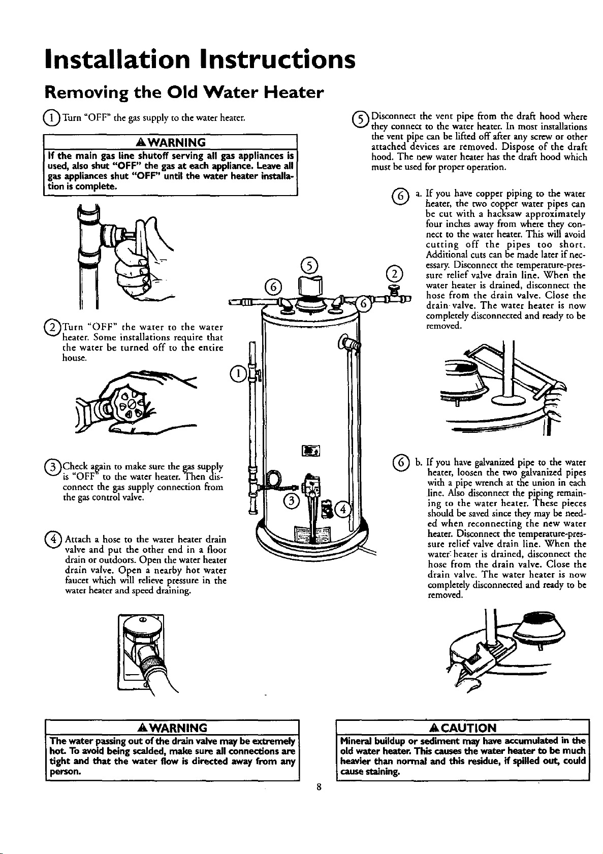
Installation Instructions
Removing the Old Water Heater
Q Turn gas supply to water
"OFF" the the heater.
AWARNING
If the main gas line shutoff serving all gas appliances is
used,also shut"OFF" the gasat eachappliance. Leaveall
gasappliances shut "OFF" until the water heater installa-
tion iscomplete.
®C3
QTurn "OFF" the water to the water
heater. Some installations require that
the water be turned off to the entire
house.
Q Disconnect the vent pipe from the draft hood where
they connect to the water heater. In most installations
the vent pipe can be lifted off after any screw or other
attached devices are removed. Dispose of the draft
hood. The new water heater has the draft hood which
must be used for proper operation.
®
® ®
a. If you have copper piping to the water
heater, the two copper water pipes can
be cut with a hacksaw approximately
four inches away from where they con-
nect to the water heater, This will avoid
cutting off the pipes too short.
Additional cuts can be made later if nec-
essary. Disconnect the temperature-pres-
sure relief valve drain line. When the
water heater is drained, disconnect the
hose from the drain valve. Close the
drain valve. The water heater is now
completely disconnected and ready to be
removed.
QCheck again to make sure the gas supply
is "OFF" to the water heater. Then dis-
connect the gas supply connection from
the gas control valve.
a
Q Attach hose the heater drain
valve and put the other end in a floor
drain or outdoors. Open the water heater
drain valve. Open a nearby hot water
faucet which will relieve pressure in the
water heater andspeed draining.
to water
AWARNING I
The water passingout of thedrain valve may be extremely
hot. To avoid beingscalded,make sure all connectionsare I
I tight and that the water flow is directed away from any
person.
Q b. you galvanized pipe to water
If have the
heater, loosen the two galvanized pipes
with apipe wrench at the union in each
line. Also disconnect the piping remain-
ing to the water heater. These pieces
should be saved since they may be need-
ed when reconnecting the new water
heater. Disconnect the temperature-pres-
sure relief valve drain line. When the
water: heater is drained, disconnect the
hose from the drain valve. Close the
drain valve. The water heater is now
completely disconnected and ready to be
removed.
i
• ACAUTION
Mineralbuildupor sediment may haveaccumulatedin the
I oldwater heater. This causesthe .waterheater to be much
heavierthan normal and this residue,if spilledout, could
causestaining.
Installation Instructions (cont'd)
Typical Installation
HOT WATER VACUUM RELIEF REQUIRED BY SOME CODES
SPACE HEATER
TEMPERED
WATER OUTLET
OUTLET (REFER TO LOCAL CODES)
TO CHIMNEY
OR GAS
VENT
MIXING VALVE
GAS
SUPPLY
I
SPACE HEATER
-- TEMPERATURE-PRESSURE
RELIEF VALVE
-- DISCHARGE PIPE
(Do not cap or plug)
-DRAIN VALVE
DRAIN PAN
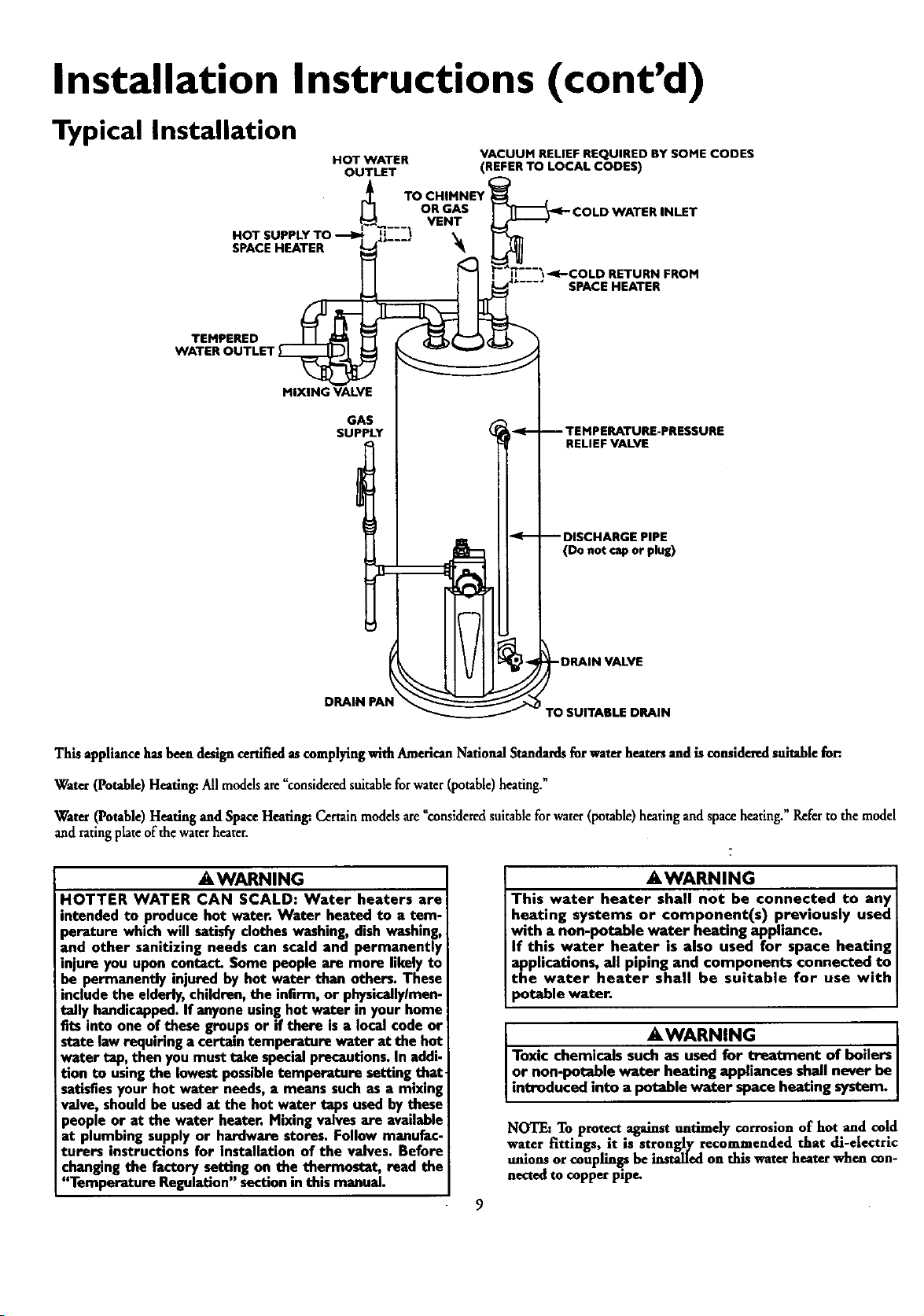
This appliance has been design certified as complying with American National Standards for water heaters and is considered suitable for.
PTO SUITABLE DRAIN
Water (Potable) Heating:Allmodelsare_consideredsuitablefor water(potable)heating."
Water(Potable)Heatingand SpaceHeating:Certain modelsare "consideredsuitablefor water(potable)heating and spaceheating." Referto the model
and ratingplateof the waterheater.
AWARNING
HOTTER WATER CAN SCALD: Water heaters are
intended to produce hot water. Water heated to a tem-
perature which wi!l satisfyclotheswashing,dish washing,
and other sanitizing needs can scald and permanently
injure you upon contact. Some people are more likelyto
be permanently injured by hot water than others.These
includethe elderly,children,the infirm, or physically/men-
This water heater shall not be connected to any
heating systems or component(s) previously used
with a non-potable water heating appliance.
If this water heater is also used for space heating
applications, all piping and components connected to
the water heater shall be suitable for use with
potable water.
AWARNING
tally handicapped.If anyoneusinghot water in your home
fits into one of these groupsor if there is a local code or
state lawrequiringa certaintemperature water at the hot
water tap, then youmust take specialprecautions.In addi-
tion to usingthe lowest possibletemperature setting that
satisfies your hot water needs, a means such as a mixing
ITo AWARNING .
xic chemicals such as used for treatment of boders
r non-potable water heating appliances sh.allnever be
ntroduced into a potable water spaceheating system.
valve, should be usedat the hot water tapsusedby these
people or at the water heater. Mixingvalvesare available
at plumbing supplyor hardware stores. Follow manufac-
turers instructions for installation of the valves. Before
changingthe factory satdng on the thermostat, read the
"Temperature Regulation"sectioninthis manual.
NOTF_ To protect against untimely corrosion of hot and cold
water fittings, it is strongly recommended that all-electric
unions or couplings be installed on this water heater when con-
nectod to copper pipe.
Installation Instructions (cont'd)
Facts to Consider About the
Location
You should carefully choose an indoor location for the new
water heater, because the placement is a very important consid-
eration for the safety of the occupants in the building and for
the most economical use of the appliance. This water heater is
not for use in mobile homes or outdoor installation.
Whether replacing an old water heater or putting the water
heater in a new location, the following critical points must be
observed.
• The location selected should be indoors as close as practical to
the gas vent or chimney to which the water heater vent is
going to be connected, and as centralized with the water pip-
ing system as possible. The water heater, as all water heaters,
will eventually leak. Do not install without adequate drainage
provisions where water flow will cause damage.
CAUTION
WATER HEATERSEVENTUALLY LEAK:Installationof the
water heatermustbe accomplishedin sucha mannerthat if
thet_nkor anyconnectionsshouldleak,the flowof waterwill
not causedamageto the structure. When suchIocatloescan-
not be avoided,a suitabledrainpanshouldbe installedunder
the water heater.Drain pansam availableat yourlocalSears
store. Sucha drain panmust be not greater than 1½inches
deep,havea minimum lengthand widthof at least2 inches
greaterthan the water heaterdimensionsand must be piped
to an adequatedrain.The panmustnot restrictcombustionair
flow. Under nocircumstancesisthe manufactureror Searsto
be heldliablefor any water damagein connectionwith this
waterheater.
AWARNING
INSTALLATIONSIN AREASWHERE FLAMMABLEUQUIDS
(VAPORS) ARE LIKELY TO BE PRESENT OR STORED
GARAGES, STORAGE, AND UTILITY AREAS, ETC):
Flammableliquids(suchasgasoline,solvents,propane(LP) or
butane, etc.), all of which emit flammable vapors,may be
improperlystoredor usedin suchareas.The gaswater heater
pilotlightor mainbunier can ignitesuchvepor_The resulting
flashbackandErecanaiusedeathor seriousburnsto anyonein
the area,as well as propertydamage.
ffinstallationin such areas is your only option, then the installa-
tion must be accomplished in a way that the pilot flame and
main burnerflame am elevated from the floor at least 18inches.
While this mayreducethe chancesofflammablevaporsfrom a
floor spillbeingignited,gasolineandotherflammablesubstances
shouldneverbestoredor usedin the sameroomor areacon-
taininga gaswaterheateror otheropenflameor sparkproduc-
ingappliance.
NOTE: Flammablevaporsmaybe drawnby air currentsfrom
other ureas of the structure to the appiiance.
• The location selection must provide adequateclearances for ser-
vicingandproper operationof the waterheater.
_,WARNING
This water heatermust not be installeddirectlyon carpe6ng.
Carpeting must be protected by a metal or wood panel
beneaththe applianceextendingbeyondthe fullwidth and
depthof the applianceby at I.east3 inches(76.2mm) in any
direction,or if the applianceis installed in an alcoveor closet,
the entirefloormustbecoveredbythepanel.Failureto heed
thiswarningmayresultinafire hazard.
_,WARNING
Minimum clearancesbetween the water heater and com-
bustibleconstructionam I" at the sidesand rear,4" at the
front,and6"fromthe ventpipe.Clearancefromthe topof the
jacketis18"onmost modelsNote that alesserdimensionmay
beallowed on some models.Referto the labelon the water
heateradjacentto the gascontrolvalveforall dearance_
AWARNING
A gaswaterheatercannotoperateproperlywithoutthe cur-
tact amountofalr for combustion.Do not installina confined
areasucha doset,unlessyouprovideairasshowninthe "Facts
to ConsiderAbout the Location"section.Neverobstructthe
flowofven61ationair Ifyouhaveanydoubtsorquestionsat all,
callyourgascompany.Failureto providethe properamountof
combustionair canresultina Ere or explosionand cancause
DEATH,SERIOUSBODILYINJUI_,ORPROPERTYDAMAGE.
_,WARNING
Ifthis water heaterwill be usedinbeautyshops,barbershops,
cleaningestablishments,or self-servicelaundrieswith dry
cleaningequipment,it isimperativethat the water heateror
waterheatersbeinstalledsothat combustionandventilation
air be taken from outsidethese areas.Referto the "Facts to
ConsiderAboutthe Location"sectionofthis manualandalso
thelatestedition of the NationalFuelGasCode,ANSI Z223.1,
alsoreferredto as NFPA54 for specificsprovidedconcerning
air required.
AWARNING
Propellantsof anrosolspraysandvolatilecompounds,(dean-
ers,chlorine basedchemicals,refrigerants,etc.) inadditionto
being highlyflammableinmany cases,will alsochangeto cor-
rosivehydrochloricacidwhen exposedto the combustion
productsofthe water h.ea...ter. The resultscanbe _zardou_
andalsocauseproductfailuro.
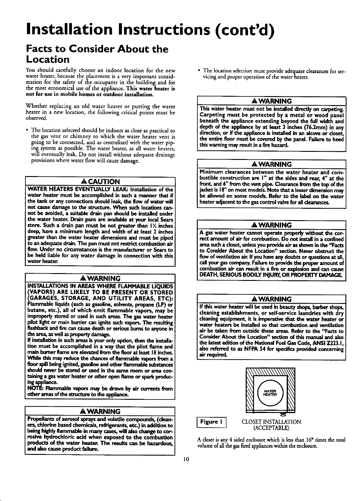
Figure I[
A closetis any4 sided enclosurewhich is lessthan 16" dmesthe total
volumeof allthe gasfired applianceswithin the enclosure.
10
CLOSET INSTALLATION
(ACCEPTABLE)

Installation Instructions (cont'd)
Facts to Consider About the
Location (cont'd)
I Figure 2 1
A room is any enclosure which is at least 16" times
greater than the total volume of all the gas fired appli-
ances within the enclosure.
Figure 3 I
An alcove suitable for the installation of awater heater is a
restricted section of a room not separated from the room
by a door or partition and which meets the minimum
clearances for the specific model water heater listed
below.
*When the ceiling height exceeds 8 feet, you are only
allowed to consider 8 feet when calculating the total vol-
ume of the enclosure.
12" MAX.
VENTILATION
ROOM INSTALLATION
(ACCEPTABLE)
ALCOVEINSTALLATION
(ACCEPTABLE)
MR O
OPENINGS
Combustion Air and
Ventilation for Appliances
Located in Unconfined Spaces
Unconfined Space is a space whose volume is not less than 50
cubic feet per 1,000 Btu per hour of the aggregate input rating
of all appliances installed in that space. Rooms communicating
directly with the space in which the appliances are installed,
through openings not furnished with doors, are considered a
part of the unconfined space
In unconfined spaces in buildings, infiltration may be adequate
to provide air for combustion, ventilation and dilution of flue
gases. However, in buildings of tight construction (for example,
weather stripping, heavily insulated, caulked, vapor barrier, etc.),
additional air may need to be provided using the methods
described in Combustion Air and Ventilation for Appliances
Located in Confined Spaces, b.
Combustion Air and
Ventilation for Appliances
Located in Confined Spaces
Confined Space is a space whose volume is less than 50 cubic
feet per 1,000 Btu per hour of the aggregate input rating of all
appliances installed in that space.
a. ALL AIR FROM INSIDE BUILDINGS:
(SeeFiguFes1through6)
The confined space shall be provided with two permanent
openings communicating directly with an additional room(s)
of sufficient volume so that the combined volume of all
spaces meets the criteria for an unconfined space. The total
input of all gas utilization equipment installed in the com-
bined space shall be considered in making this determination.
Each opening shall have a minimum free area of one square
inch per 1,000 BTU per hour of the total input rating of all
gas utilization equipment in the confined space, but not less
than 100 square inches. One opening shall commence within
12 inches of the top and one commencing within 12 inches
of the bottom of the enclosure.
DOOR
FRONT VIEW
OF DOOR AIR DUCT
[ Figure 4 I [FigureS]
Minimum clearances between the water heater and
combustible construction are listed below,
Minimum Side & Rear Clearances -- I"
Minimum front clearancefrom jacketto closet door m 4"
Minimum ceiling clearance from jacket top to com-
bustible ceiling -- 18".
MAX.
AWARNING
_'_" MIN.
AS VEi_T
Figure 6 ]
b. ALL AIR FROM OUTDOORS: (see Figures7 through 9,
_a_e t2)
e confined space shall be provided with two permanent
openings, one commencing within 12 inches of the top and
one commencing within 12 inches from the bottom of the
enclosure. The openings shall communicate directly, or by
ducts, with the outdoors or spaces (crawl or attic) that freely
communicate with the outdoors.
11

Installation Instructions (cont'd)
Combustion Air and
Ventilation for Appliances
Located in Confined Spaces(cont'd)
5. Louvers and Grilles: In calculating free area, consideration
shall be given to the blocking effect of louvers, grilles or
screens protecting openings. Screens used shall not be smaller
than ¼ inch mesh. If the free area through a design of louver
or grille is known, it should be used in calculating the size
opening required to provide the free area specified. If the
design and free area is not known, it may be assumed that
wood louvers will be 20-25 percent free area and metal louvers
and grilles will have 60-75 percent free area. Louvers and
Figure 7 [
1. When directly communicating with the outdoors, each open-
ing shall have a minimum free areaof 1square inch per 4,000
BTU per hour of total input rating of all equipment in the
enclosure. (See Figure 7.)
2. When communicating with the outdoors through vertical
ducts, each opening shall have a minimum free area of 1 "
s,_uareinch per 4,000 BTU per hour of total input rating of
all equipment in the enclosure. (See Figure 8.)
ALT INLET AIR VEt4TIU_TIOfl LOUVERS
grilles shall be fixed in the open position or interlocked with
the .equipment so. that they are opened automatically during
equ,pment operanon.
6. Special Conditions Created by Mechanical Exhausting or
Fireplaces: Operation of exhaust fans, ventilation systems,
clothes dryers or fireplaces may create conditions requiring
special attention to avoid unsatisfactory operation of installed
gas utilization equipment.
Water Piping
Figure 8 ]
3. When communicating with the outdoors through horizontal
ducts, each opening shall have a minimum free area of 1
square inch per 2,000 BTU per hour of total input rating of
allequipment in the enclosure. (See Figure 9.)
4. When ducts are used, they shall be of the same cross-sectional
area as the free area of the openings to which they connect.
The minimum short side dimension of rectangular air ducts
shall not be lessthan 3 inches. (SeeFigure9.)
AWARNING
HOTTERWATERCAN SCALD:.Water heatersareintendedto
producehot water.Water heatedto a temperaturewhichwill
satisfydotbeswashing,dishwashing,andothersanitizingneeds
canscaldandpermanentlyinjureyouuponcontact.Somepea-
piearemoreI!kelyto be permanentlyinjured byhotwaterthan
others.Theseincludethe elderly,children,theinfirm,orphysiczi-
lylmentzilyhandicapped,ffanyoneusinghotwaterinyour home
fitsintooneofthesegroupsor ifthereisa localcodeorstatelaw
requidnga certaintemperaturewater at thehotwatertap,then
mumusttakespecialprecaul_ol_Inadditionto usingthe lowest
mssibletemperaturesettingthat satisfiesyourhotwaterneeds,
Lmeanssuchasamixingvalve,shouldbe usedatthehot water
tapsusedbythese peopleor at the waterheater.Mixingvalves
areavailableat plumbingsupplyor hardwarestore_Followman-
ufacturersinstructionsfor installationof the valves.Before
changingthe factory setting on the thermostat, read the
'q'emperatureRegulation"sectioninthis manual.
This water heater shall not be connected to any heating systems
or component(s) used with a non-potable water hearing
appliance.
Ifa water heater is installed in adosed water supply system; such as
one having a back-flow preventer, check valve, water meter with a
check valve,etc.., in the cold water supply; means shall be provided
to control thermal expansion. Contact the local utility or local Sears
ServiceCenter on how to control this situation.
NOTE: Toprotect against untimely corrosion of hot and
cold water fittings, it is strongly recommended that all-elec-
tric unions or couplings be installed on this water heater
when connected to copper pipe.
NOTE: If using copper tubing, solder tubing to an adapter
before attaching the adaptor to the cold water inlet connection.
Do not solder the cold water supply line directly to the cold
water inlet. It will harm the dip tube and damage the tank.
:12

Installation Instructions (cont'd)
Temperature-Pressure Relief Valve
_,WARNING
At the time of manufacturethis water heater wasprovided
with a combinationtemperature-pressuresrelief valvecerti-
fied by a nationallyrecognized testinglaboratorythat main-
teins periodicinspectionofproductionof listedequipmentor
materials,asmeetingthe requirements for ReliefValvesand
Automatic Gas Shutoff Devices for Hot Water Supply
Systems,andthe latest editionof ANSI Z21.22 andthe code
requirements of ASME.If replaced, the valvemust meet the
requirements of localcodes,but not lessthana combination
temperature and pressurerelief valve certified as meeting
the requirements for Relief Valves and Automatic Gas
ShutoffDevicesfor Hot Water SupplySystems,ANSI Z21.22
bya nationally recognized testing laboratorythat maintains
periodic inspection of production of listed equipment or
materials.
The valvemust be markedwith a maximumsetpressurenot
to exceedthe marked hydrostaticworkingpressureof the
water heater (150 IbsJsq.in.) and a dischargecapacitynot
lessthanthewater heater input rate asshownon the model
rating plate. (Electric heaters- watts dividedby 1000x 3415
equalBTU/Hr.rate.)
Yourlocaljurisdictionalauthority,whilemandating the useof
a temperature.pressure relief valve complyingwith ANSI
Z21.22 and ASME, may require a valvemodeldifferentfrom
the onefurnishedwith the water heater.
Compliancewith suchlocal requirements must be satisfied
bythe installeror enduserofthe water heater with a locally
prescribedtemperature-pressurerelief valveinstalledin the
designatedopeninginthe water heater in placeofthe facto-
ry furnishedvalve.
Forsafeoperationof the water heater, the relief valvemust
not be removed from it'sdesignatedopeningor plugged.
The temperature.pressure relief valve must be installed
directlyintothefittingof the water heaterdesignatedfor the
relief valve.Positionthe valvedownwardand providetubing
sothat any dischargewill exit onlywithin 6 inchesabove, or
at any distancebelowthe structuralfloor.Be certain that no
contactis made with any live electricalpart. The discharge
openingmust not be blockedor reduced in size under any
!circumstances. Excessivelength,ov.er 15feet, or useof more
than two elbows can cause restriction and reduce the dis.
chargecapacityofthevalve.
No valveor other obstructionis to be placedbetween the
relief valveand the tank. Do not connecttubing directlyto
dischargedram unlessa 6" air gap is provided.To prevent
bodilyinjury,hazard to life, or property damage,the relief
valvemustbeallowedto dischargewater inquantitiesshould
circumstancesdemand.If the dischargepipeisnot connect.
ed to a drain or other suitablemeans,the water flow may
causepropertydamage.
The DischargePipe:
Mustnot besmaller in sizethanthe outlet pipesizeofthe
valve,or haveanyreducingcouplingsor otherrestrictions.
Mustnotbe pluggedor blocked.
Mustbeofmaterial listedfor hotwater distribution.
Must beinstalledsoasto allow completedrainageof both
the temperature.pressurerelief valve, and the discharge
pipe.
Mustterminate at an adequatedrain.
Mustnot haveanyvalvebetween the relief valveand tank.
_,WARNING
The temperature.pressure relief valve must be manually
operated at least oncea yea_ Caution shouldbe takento
ensurethat (I) no one isin front of or aroundthe outletof
the temperature-pressurerelief valvedischargeline,and.(2)
the water manually dischargedwill not causeany boddy
injury or property damage becausethe water may be
extremelyhot.
If after manuallyoperatingthe valve,it failsto completely
resetand continuesto releasewater, immediatelyclosethe
cold water inlet to the water heater, follow the draining
instructions,and replace the tomperature-pressuro relief
valvewithanew one.
_,WARNING
If a water heater is installed in conjunction with a sep-
arate storage vessel, the storage vessel must also be
equipped with a temperature-pressure relief valve
complying with the Standard for Relief Valves and Hot
Water Supply Systems, ANSI Z21.22. The hourly
rated temperature steam BTU discharge capacity of
the temperature-pressure relief valve(s) shall not be
less than the combined BTU input of the water
heater(s) supplyingwater to the storage vessel(s).
_ _ { _ SHUTOFF
ALVE
PRESSURE
RELIEFVALVE
[] (Do not cap or plug)
DISCHARGE PIPE
RELIEFVALVEOPENING
At thetimeofmanubcture,thiswaterheaterwasprovidedwith acombinationtem-
perature-pressurereliefvalvelistedas complyingwiththe sranda_forr_ief _es
andautomategasthut-o_"devicesfor hot watersupplysystems,ANSIZ21.2Z For
safeoperationof the wter heat_,thereliefvatvemustnotberemovedfromitsdes-
ignatedpointof inmlladonor plngzed.
Yourlocaljurisdictiomdauthority,whilemandatingthe useofatemperature-pr_sure
reliefva_ €ompF/ingwithANSI7.21.22andASME,mayrequirea _lve modeldiffer-
entfromthe onefurnishedwiththewaterheater
CompliancevHthsuchlocalrequirementsmustbesatis_edbytheinsullerorenduser
of the water heaterwith z locaffyprescribedtemperature-pressurereliefvalve
imtailedinthedesignated_mLng fu thewaterheater.
Seem_nualheading-"Tempe_trJre-PressureRelief_'_" _" installationandmalnte-
nanceof ref_-_valve,dischargeline,andothersafetyprecautions.
13

Installation Instructions (cont'd)
Filling the Water Heater
. ACAUTION
Never usethiswater h_ completelyfilled with
water.To preventdamageto the tank,the tank mustbe filled
with water• Water must flow from the hot water faucet
before turnng ON gastothe water heater.
To fill tee water heater with water:
• Close the water heater drain valve by turning the handle to
the right (clockwise). The drain valve is on the lower front of
the water heater.
• Open the cold water supply valve to the water heater.
NOTE: The cold water supply valve must be left open
when the water heater is in use.
• To insure complete filling of the tank, allow air to exit by
opening the nearest hot water faucet. Allow water to run
until a constant flow is obtained. This will let air out of the
water heater and the piping.
Check all new water piping for leaks. Repairasneeded.
Venting
TO CHIMNEY
PLACE
A WARNING
To insureproper ventingof this ges-flred water heater, the
correctvent pipediameter mustbe utilized.Anyadditionsor
deletionsofothergasapplianceson a commonvent with this
water heatermayadverselyaffectthe operationof thewater :
hea_er.Consultthe localSearsServiceCenter or gasutilityif
anysuchchangesare planned.
Forproper venting in certain installations, a larger diameter vent
pipe may be necessary. Due to great variances in installations,
unforeseeable by the manufacturer of the water heater,you must
consult your gas company to aid you in determining the proper
venting foryour water heater from the vent tables in the latest edi-
tion of the National FuelGas Code ANSI Z223.1, alsoreferred to
asNFPA 54.
Cheek the venting system for signs of obstruction or deterioration
and replace if needed.
The combustion and ventilation air flow must not be obstructed.
AWARNING
Obstructed ordeteriorated vent systems maypresentaserious
healthriskorasphyxiation.
• A,VVARNING ]
The water heaterwtth_led mustbe properlyI
vented to a chimneywhichterminatesoutdoors.Neveroper-I
atethewaterheaterunle_,it isven,.t_lto the outdoorsand hasI
adequate;urm[_,ly to avoidrisksof |mpreper operation,explo-[
sionorasphyxlmon. ]
The draft hood supplied with this water heater must be installed as
shownbefor.ethe heater isoperated.
If the draft hood is removed for cleaning or replacement it must be
replacedin reverseorder as removed.
AWARNING
VENT DAMPERS- Any vent damper,whether it isoperated
thermallyorotherwisemustberemovedif itsuseinhibitsprop
er draftingofthewaler heater
ThermallyOperated Vent Dampers:Gas-firedwater heaters
havingthermal efficiencyin excessof 80%mayproducea rela-
tivelylowfluegas_ratore. Suchtemperaturesmaynotbe
high enough to properly open thermally operated vent
dampers,Thiswouldcausespillageof fluegasesandmaycause
carbonmonoxidepoisoning.
Ventdampersmustbearevidenceof certificationascomplying
with the latestedition of American NationalStandardANSI
7.21•68 (ANSI Z21.66& 67, respectively,coverelectricallyand
mechanicallyactuatedventdampers)•Beforeinstallationofany
ventdamper,censultYourI°calSean ServiceCenter °r the gas
utilityfor furtherinformatio_
AWARNING
The ventpipefromthewater heatermustbe nolessthan the[
diameter ofthe draft hoodoutlet on the water heater,and I
[ _ slope upward to the chlmney at least ¼ inchper linearI
All vent gases must be completely vented to the outdoors of the
structure (dwelling). Installonly the draft hood provided with
the new water heater and no other draft hood.
Vent pipes must be secured at each joint with sheet metal screws.
J TO
,N --ff CMIM"EY
MIN. ¼
RISE PER LINEAR
FOOT
VENT PIPE INSTALLATION
14

Installation Instructions (cont'd)
Venting (cont'd)
There must be a minimum of 6" dearance between single wall
vent pipe and any combustible material. Fill and seal any clear-
ance between single wall vent pipe and combustible material
with mortar mix, cement, or other noncombustible substance.
For other than single wall, follow vent pipe manufacturer's clear-
ance specifications. To insure a tight fit of the vent pipe in a
brick chimney, seal around the vent pipe with mortar mix
cement,
AWARNING
FailureW haverequired clearancesbetweenventpipingand
combustiblematerialwillresult in afire hazard.
Where an exhaust fan is installed in the same room as the
water heater, air will be drawn into the room through the
chimney. Air supply openings must be large enough to admit
air exhausted by the fan ant1 that required'by all gasburning
appliances. A down-draft or back-draft willprevent proper
combustion, causing soot which may result in serious damage
to the water heater.
Where continuous or intermittentbackdraft is found to exist,
check chimney conditions, in some cases a blower type flue
gasexhauster must be employed between the appliance and
the stack to assureproper venting and correct combustion.
Combining vents as shown below is satisfactory, providing the
basic rules of good venting are observed. In either case the
vertical rise ab6ve drafthood (X)before any fittings should be
as great as possible. All venting connections should be made
in accordance with local codes and ordinances.
AWARNING
Minimum clearancesbetween the water heater and com-
bustibleconstructionare I" at the sidesand rear, 4" at the
front,and6"fromthe ventpipe.Clearancefrom the top ofthe
acketis18"onmostmodelgNote that a lesserdimensionmay
_eallowedon somemodelg Referto the labelon the water
heateradjacentto the gascontrolvalveforalldearance_
AWARNING
A gaswaterheater cannotoperateproperlywithoutthe cor-
_'t amountofair for combustion.Do not installina confined
areasucha closet,unlessyouprovideair asshowninthe "Facts
to ConsiderAbout the Location"section.NeverobsmJctthe
flowofventilationair.If you haveanydoubtsor questionsat all,
callyour gascompany.Failureto providethe properamountof
combustionair canresult in a Ereor explosionand cancause
DEATH,SERIOUSBODILYINJUR_,ORPROPERTYDAMAGE.
Besurevent pipeisproperlyconnectedto preventescapeof
dangerousfluegaseswhichcouldcausedeadlyasphyxiation.
AWARNING I
AWARNING
Chemicalvapor corrosionof the flue and vent systemmay
occurif air for combustioncontainscertain chemical vapors.
Spraycanpropellents,cleaningsolvents,refrigerator and air
conditionerrefrigerants, swimmingpool chemicals,calcium
andsodiumchloride,waxes,bleach,andprocesschemicalsam
typicalcompoundswhicharepotentiallycorrosive.
When vents are combined, area of the combined vent
should be equal to area of the largest single vent, plus 50%
of area of all others joining it.
EXAMPLE: To combine two 6" vents with an 8" vent, the
VENT SQUARE
SIZE INCHES
area of a combined vent should be one half
area of two 6" vents (14+14) plus area of 8"
vent (50) = 78 sq. inches. Referring to chart 78
sq. nchesrequires a 10" diameter vent.
S" 20
6" 28
7" 38
8" 50
9" 64
VENT SQUARE
SIZE INCHES
I0" 79
12" 113
14" 154
16" 201
18" 254
Gas Piping
AWARNING
Make surethe gassuppliedisthe same type listedon the
modelrating plate. The inlet gaspressuremust not exceed
10.5incheswater column(2.6kPa) for Natural Gas and 13
incheswater column (3.SkPa)for Propane (LR) Gas.The
minimuminlet gaspressurelistedon the modelrating plate
isfor the purposeofinputadjustment.
AWA.RNING , I
Ifthe gascontrolvalveissubjectedto pressuresexceeding½ I
poundper squareinch(3.SkPa),the .d.d.d.d.d.d.d.d.d._to the gascon-
tml valvecouldresultinafire or explosmnfrom leakinggas.
AWARNING I
If the maingasline shutoff sorv|ngall gasappliancesis used,I
alsotorn "OFF" the gasat eachappliance.Leaveallgasappli-
ances shut offuntilthe water heaterinst_dla_onis complete.
15

Installation Instructions (cont'd)
Gas Piping (cont'd)
CORRECT GAS PIPE SIZE FOR
WATER HEATERS OPERATING ON NATURAL GAS
Basedon Inlet Gas Pressuresof0.5 psigor Lessand
a Pressure Drop of 0.3 inchesWater Column.
(Based on a 0.60 Specific Gravity Gas)
TOTAL INPUT* DISTANCE TO METER, IN FEET
BTU/HR 20 30 60 90 125 150 200
75,000 I/2 3/4 3/4 3/4 I 1 I
100,000 3/4 3/4 3/4 I I I I
150,000 3/4 3/4 I I II/4 1% IJ/4
*Of all gas appliances in line.
A gas line of sufficient size must be run to the water heater.
Consult the latest edition of National Fuel Gas Code ANSI
Z223.1, also referred to as NFPA 54 and the gascompany con-
cerning pipe size.
There must be:
A readily accessible manual shut off valve in the gas supply line
i serving water heater,
the and
A dripleg (sediment trap) ahead of the gascontrol valveto help
prevent dirt and foreign materials from entering the gas control
Valve.
• A flexible gas connector or a ground joint union between the
shutoff valveand control valve to permit servicing of the unit. _"
Be sure to check all the gas piping for leaks before lighting the
water heater. Use a soapy water solution, not a match or open
flame. Rinse offsoapy solution and wipe dry.
GAS PIPING WITH
FLEXIBLE CONNECTOR
MANUAL _(;AS SUPPLY PIPING
SHUTOFF
VALVE
FLEXIBLE GAS CONNECTOR
LABELED AS COMPLYING
"_ WITH ANSI STANDARDS
GROUND JOINT L_ _a_ LOOP
UNION (Optional) _:( _" T_
--r-
GAS
3" MnN.I I DRIPLEG
_._l [ (s_im"tt"p)
_5 CAP
GAS PIPING WITH ALL BLACK IRON
PIPE TO GAS CONTROL
GAS SUPPLY PIPING
MANUAL
SHUTOFF
CONTROL
VALVE
When installed at elevations above 2,000 feet, the input rating
should be reduced at the rate of 4 percent for each 1,000 feet above
sea level. Contact your localSears Service Center orgas utility for
further information.
f AWARNING
The appliance and its_ must be leak tested
beforeplacingthe applianceinoperation.
AWARNING
• The applianceand itsindividualshutoffvalvemustbe discon-
nectedfromtbe gassopplypiping systemduringany pressure
testing of the gas system at test pressuresinexcessof ½
poundpersquareinch(3.SkPa).
• The appliance must be isolatedfrom the gassupply plpingsys-
tom by dosing its individual manual shutoff valve during any
pressure testing of the gas supply piping system at test pres-
suresequal or lesst_n ½ pound per square inch(3.SkPa).
• . . _E,WARNING . ]
Use pupeiountcompo_tape marked as being I
n_mnt to_ea_°nofPe_°g_m0'n_ne0-R)]Ps_ J
VALVE _
-_ BLACK PIPE
GROUND _ / [_:
JOINT UNION _ _./
CONTROL
VALVE
_[____ ] [ (Sediment trap)
[_ CAP
AWARNING
Contaminantsinthe gaslinesmay causeimproperoperation
of the gas control valve that may resolt in flr_ or explosion.
Before attaching the gasline be sure that all gas pipe isdean
on the inside. To trap any dirt or foreign material in the gas
supply line, a drip leg (sometimes called a sediment trap)
must be incorporated in the piping• The drip leg must be
readily accessible. Install in accordance with the "Gas Pnping"
section.Referto the latestedition of the National FuelGas
Code,ANSI Z223.1, alsoreferredto asNFPA 54.
16

Installation Instructions (cont'd)
Installation Checklist
BEFORE LIGHTING THE PILOT:
Check the gasfines for leaks.
a. Use a soapy water solution• DO NOT test for gas leaks
nsinga match or openflame.
Ix Brush the soapy water solution on all gaspipes, joints and
fimngs•
c• Check for bubbling soap. This means you have a leak.
Turn OFF gas andmake the necessary repairs.
d. Recheck for leaks.
e. Rinse offsoapy solution and wipe dry.
• Is the new temperature-pressure relief _ properly installed
and piped to an adequate drain?See Temperature-Pressure
Re_ef Valve_section•
• Are the cold and hot water lines connected to the water
heater correctly? See _Water Piping" instructions in the
"Installation Instructions _ section.
• Is the water heater completely filled with water. See Filling
instructions m the Installauon Instructions section.
• Will a water leak damage anything? See the "Facts to
Consider About the Location" section•
HOT
GAS SUPPLY
SHUTOFF VALVE
VENT PIPE TO
OUTDOORS
OR CNINNEY
DRAFT HOOD
SHUTOFF VALVE
COLD
UNION
TEIq PERA11JRE-
J PRESSURE
REUEF VALVE
-- DISCHARGE PIPE
(Do not cap or plug)
• Is there proper clearance between _e water heater and any-
thing that might catch fire? See the Facts to Consider About
the Location"section.
• Do you have adequate ventilation so that the water heater
will operate properly? See "Combnsdon Air and Ventilation"
in the "Installation Instructions"section.
• Is the draft hood vent piping properly secured. See Venung
instructions in the "Installation Instructions" section.
• Is there proper clearance between the vent pipe and anything
that might catch on fire? See Venting instructions in the
"Installation Instructions" section.
• Is the vent pipeproperly sloped and does the vent terminate
outdoors? See "Venting" instructions in the Installation
Instructions" section•
Do you need to call your gas company to check the gas pipe
and its hookup?
TEE ----41
DRIP LEG "--Jim
(Sedim_,__)
CAP -_
DRAIN VALVE -'-"
FLOOR DRAIN
_ oNiwor_4 _ otnurr W_'llm _qBRI_'nwR Im'.
_ SlOTWIIIAIS a_ITh_ Im_l "_O_ BAB_.
S4OCg.mltmBq
G&EWATERFF.ATER "NRTI."_
I
1as I
" AIR GAP
17
MODEL RATING PLATE

Operating Instructions
Lighting
AWARNING
BEFORE LIGHTING [PROPANE (L.P,) GAS WATER
HEATERS].Propane(LR) gasisheavierthanair. Shouldthem
be a leak In the system,the gaswill settle near the ground.
Basements,cra.w.Ispaces,sldrtedareas undermobile homes
(evenwhenventilated},€loseesandm belo)v.._nd levelwill
serve as pocketsfor the accumulationof this gas. _elore
attempting to lightor .r_.ightthewaterheater'spilotor turning
a ,ght absulu ysuremy ,sno
accumulatedgasmthearea.Searchforodorofgas.by.miffing
groundlevelln the vidnityofthe appliance,If odorisoetecteo,
follow stepsmd_ at "For YourSafety"onthecoverpagem
thismanualthen |easethepremis_
Lighting and operating instructions are located on front of the
waterh_ater, above or to one side of the gas control valve.
AWARNING
AN ODORANT IS ADDED TO THE GAS USED
FORYOUR SAFETY
IF YOU SMELLGAS:
Do not Cryto lightanyappliance.
Do not_o_h anyelectrk_ switch;do not useanyphonein
yourbujIding.
Immediatelycallyour gassupplierfrom a neighbePsphone.
Followthe gassupplloeasinstructlom_
If you cannot reach your gas supplier, call the fire
department.
BYTHIS WATER HEATER.
I Figure I 0]
IFigure I I]
AWARNING
DO NOT force the gas€oatrol knob.Use only your handto
pushit downto lightthe pilot, orto tom it to "ON", "OFF:'
or "PILOT". Never usea tool such asa lever,wrenchor ph-
ers. Do not hit or damagethe knob.A damagedknob may
resu!tin an expinslonand serious .injury.If you havepint:gem
turningthe knob, callthe gassupplier immediately.
CHECK FOR LEAKS
Be sure to check all your gas pipes for leaks before lighting your
water heater. Use a soapy water solution, not a match or open
flame. Check the Factorygas fitting, aEer pilot is lit and g__con-
trol knob is still in "PILOT" position. Then, check the fittings
when the main burner is turned "ON". Use a soapy water sohi-
tion for this, too.
18
I
I
I
OUTER DOOR

Operating Instructions (cont'd)
Lighting label on the water heater as it appears above the thermostat
YOUR SAFETY READ BEFORE LIGHTING
If you do not follow these instructions exactly, • fire or explosion
I WARNING
may result causing property damage, personal Injury or loss of life.
A. Thisappliancehas a pilot which must be rightedby
hand.Whenlightingthe pilot,followthese Instructions
exactly.
B. BEFORELIGHTINGsmellall aroundtheappliancearea
for gas. Be sure to smell next to the floor because
somegasis beavlerthanairandwillsettleonthe floor.
WHATTODOIF YOUSMELLGAS
• Donottryto lightanyappliance.
• Do not touch any electric switch;do not use any
phoneInyourbuilding.
• Immediatelycell yourgassupplierfroma neighbor's
phone.Followthegassuppller'sinstructions.
LIGHTING INSTRUCTIONS
1.STOP!Readthesafetyinformationaboveonthislabel.
2.Removeouterdoor.
3.Set the thermostat to lowest setting byturning the
watertemperaturedialclockwise,( _ )to itslowest
temperaturesetting(witharrowon dial)as shown.DO
NOT FORCE.
_,.Turngascontrolknobclockwise_') to "OFF"posi-
tion. Knobcannotbe turnedfrom "PILOT"to "OFF"
unlessknobIs depressed slightly.DO NOT FORCE.
(Figure10,page18)
S.Waltfive (5) minutesto clearout any gas. If youthen
smell gas,STOPIFollow"B"In the safetyinformation
aboveon this label. If you don't smellgas, go to the
nextstep.
6. Remove(or open) Inner door locatedbelowthe gas
controlunit.(Figure13 page18)
7. Findpilot,-followmetaltubefromgas control.Thepilot
Islocatedonthe righthandsldeofthe burner.
PILOT BURNER /_11
8.Ifyoudon1smellgas,turnknobongascontrolcounter
clockwlse_@ to"PILOT'pasltion.(Figuretf, page18)
_ n
THERMOCOUPLE
• If you cannotreachyour gas supplier,call the fire
department.
C.Use onlyyourhandto pushIn orturn the gascontrol
knob.Neverusetools.Ifthe knobwillnotpush Inor
turnbyhand,don'ttryto repairit,cell a qualifiedser
vicetschnlclan.Forceor attemptedrepairmayresult
insfire orexplosion.
D. Do not usethis applianceit anypart hasbeenunder
water.Immediatelycall a qualifiedservice technician
toInspecttheapplianceandto replaceany partof the
controlsystemandany gascontrolwhichhas been
underwater.
9. Push in control knob all the way and hold down.
Immediatelylightthe pilot with a match. Continue
to hold control knob in for about one (1) minute
after the pilot Is lit. Release knob and it will pop
back up. Pilot should remain lit. If it goes out,
repeatsteps3 through8.
• If knobdoesnotpop upwhenreleased,stopand
Immediatelycall your servicetechnicianor gas
supplier.
e If the pilot will not stay lit after several tries,
depressandturnthegas controlknobclockwise
_'_ to"OFF"andcallyourservice tschnlclan
orgassupplier,(Figure10,page18)
10, Replace(orclose)Innerdoor.Replaceouterdoor If
doordoesnotcovergas controlon/offknobor tam-
poretureadjustmentknob. (Figure13,page18)
11. Atarmslengthaway,turngascontrol knob counter-
clockwise _l(_ to the full "ON" position,
WARNING Do not use gas control knobto reg.
ulate gas flow. (Figure12,page18)
12.At armslengthaway,set the thermostatto desired
setting.Themark( • ) NOTIndlcetlveof approximate
120°F Is preferred startingpoint. Some local laws
mayrequirea lower startingpoint,If hotterwaterIs
desired,seeInstructionmanualand"warning" below.
13.ReplacetheouterdoorIfnotreplacedinstep10,
HotterwaterIncreasesthe risk ofscald injury.Beforechangingtemperaturesettingsee Instructionmanual.
WARNING
TO TURN OFF GAS TO APPLIANCE
I. Set the thermostatto lowestsetting by turningthe
watertemperaturedialclockwise(f_) to Itslowest
temperaturesetting(witharrowondial)as shown.DO
NOT FORCE.
2.Turngascontrolknobclockwise_,) to"OFF"posk
tlon. Knobcannotbe turnedfrom "PILOT"to "OFF"
unlessknobIsdepressedslightly.DO NOT FORCE.
(Figure10,page18)
3.Replaceouterdoor(ifremoved).
19

Operating Instructions (cont'd)
Temperature Regulation
Due to the nature of the typical gas water heater, the water tem-
perature in certain situations may vary up to 30°F higher or
Iower at the point of use such as, bathtubs, showers, sink, etc.
This means that when the temperature adjustment dial is set at
the markapproximating 120" F, the actual water temperature at
any hot water tap could be as high as 150°F oras low as 90"E
Any water heater's intended purpose is to heat water. Hot water
is needed for cleaning (bodies, dishes, clothing). Hot water will
present a scald hazard. Depending on the time dement, and the
people involved (normal adults, children, toddlers, elderly,
infirm, etc.) scalding may occur at different temperatutes.
AWARNING
HOTTERWATERCAN S_. Water heatersare intendedto
producehot water.Water heatedto a temperaturewhichwill
satisfyclotheswashing,dishwashing,and othersanitizingneeds
canscaldandpermanentlyinjureyouuponcontact.Somepeo-
_ aremorelila.,lyto be pem_nantly injuredbyhot waterthan
others.These indude the elderly,children,the infirm, or physical-
ly/mentally handicapped.If anyoneusinghot water inyour home
fitsintooneofthesegroupsor ifthereis alocalcedeorstatelaw
requiringacertaintemperature waterat thehotwatertap,then
_u musttakespecialprecaution_Inadd'_ionto usingthe lowest
msslbietemperaturesettingthat satls¢_yourhotwaterneeds,
a meanssuchasa mixingvalve,shouldbe usedat thehot water
tapsusodbythesepeopleor at the waterheater.Mixlng_ralves
areavailableat plumbingsupplyorhardwarestores.Followman-
ufacturersinstructionsfor installationof the valves.Before
changing the factory setting on the thermostat, readthe
'fl'emperatureRegulation"sectioninthismanual.
Turn the water temperature dial dochvise.._i""_) to decrease
the temperature, or counterdockwise (4" _'_) to increase the
temperature.
E
V- Is a thermostat setting of approximately 120°F,
which will supply hot water at the most economi-
cal temperatures. The temperature adjustment
knob can be turned lowerif desired.
A-Is a thermostat setting of appmximatdy 130°E
13-Is a thermostat setting of approximately 140°E
C-Is a thermostat setting of approximately 160°E
VERY HOT- Is a thermostat setting of 180°E It is recommend-
ed that the dial be set lower whenever possible.
AWARNING
Neverallow smallchildrento usea hot water _ or to draw
their ownbathwater.Never leavea childor handicappedper-
sonunattended na bathtubor shower.
The thermostat of this water heater has been factory set at its
lowest position, to reduce the riskof scald injury. It is adjustable
and must be reset to the desired temperature setting. The mask
(V) indicative of approximately 120°F is the preferred starting
point. Some states have a requirement for a lower setting. If you
need hotter water, follow directions for temperature adjustment,
but beware of the w_rnings in this section.
NOTE: Water temperature range of 120°--140°F recom-
mended by most dishwasher manu_gacUucrs.
AWARNING . I
Shouldoverheatingoccuror the gassupplyfallto shut off,
tom "OFF" the manualgascontrolvalveto the appliance.
2O

Service and' Adjustment
Tank (Sediment) Cleaning
Sediment build-up on the tank bottom may create varying
amounts of noise, end if lef_ in the tank will cause premature
tank failure. In some water areas, you may not be able to drain
all sediment deposits by simply draining the tank. In these cases
Mag Erad (part no. 23600) can be used to help remove the sedi-
ment deposits. This may be ordered from the Sears Service
Center. For ordering, refer to the _PartsOrder List section.
Venting System Inspection
At least once a year a visual inspection should be made of the
venting system. Youshould look for:
Obstructions which could cause improperventing. The com-
bustion and ventilation air flow must not be obstructed.
Damage or deteriorationwhich could cause improper venting
i or leakage products.
Rusted flakes around top of water heater.
Chemicalvapor corrosionof the flue and vent systemmay
occurif air for combustioncontainscertainchemicalvepor_
Spraycan propellants,cleaningsolvents,refrigeratorand air
conditionerrefrigerants,swimmingpoolchemicals,calcium
andsodiumchloride,waxes,bleach,and processchemicalsare
typicalcompoundswhicharepotentiallycorrosive.
of combustion
AWARNING
Burner Inspection
• AWARNING
Do notusothisapldiancaifanypartofitIresbeanunderwater.I
Immediately calla SearsServiceTechnicianto inspectthe I
applianceandto replacethe gas control or any part of the I
bu whkh I
At least once ayear a visual inspection should be made of the
main burner and pilot burner. The drawingis for your reference.
You should check for sooting which is not normal and will
impairproper combustion.
AWARNING
Soot build-up indicatesa problem that requires correction
beforefu..rt_r. u_..Turn'_DFF"gasto water heaterand leave
"OFF" until rel_.rs are made,becausefailureto correctthe
causeof the sooting can resultin a fire or explose)n cau_ng
DEATH,SERIOUSBOD LY NJUR%,ORPROPERTYDAMAGE.
AWARNING
_ ordeterio_a_l vent systemsmay present a serious
healthriskor asphyxiation.
.wA.,NO I
Be sure the vent pip_onnected to prevent I
esc,ape,of dangerous flue gasseswhich could cause deadly
asphyx_a_on. J
AWARNING ]
If afte.rinspectionof .the.ventsystemyou found sootingor I
deterioration,somethingmwcon_ Callthelocalgasutilityto
correctthe p.roblem_ cleanor replacetheflueandventingI
beforeresumingoperationof the water heater. J
Burner Cleaning
In the event your burner needs cleaning, use the following
instructions:
If inspection of the burner shows that cleaning is reauired, turn
the gas control knob clockwise (_x,) to the "OF_:_ position,
depressingslighdy.
NOTE: The knob cannot be turned from "PILOT" m "OFF"
unless knob is depressed slightly. DO NOT FORCE.
Loose deposits on or around the burner can be removed by care-
fully using the hose of a vacuum cleaner inserted through the
accessdoor of the water heater. If the burner needs to be removed
for additional deening, call the Sears Service Center to remove
and dean the burner end correct the problem that required the
burner to be deened.
21

Service and Adjustment (cont'd)
Draining
The water heater should be drained if being shut down during
freezing lempetat_ea. Also periodic draining and cleaning of
sediment from the tank may be necessary.
Turn the gas control knob to the "OFF" position.
CLOSE the cold water ialet valve to the water heater.
OPEN a nearby hot water faucet and leave open to allow for
draining.
Connect a hose to the drain valve and terminate to an ade-
_patCdrain.
EN the water heater drain valve to allow for tank
draining.
NOTE: If the wat_ htat_ is going to b¢ shut down and
drained for an extended period, the drain valve should be
left open with hose connected allowing water to terminate
to an adequate drain.
• Close the _"aiu valve.
• Follow instructions in the "Filling The Water Heater"
section.
Follow the lighting instructions in the "Lighting _ section to
restart the water beater.
Temperature-Pressure Relief
Valve Operation
The tempetature-premure relief valve must be manually operated
at least once a year.
TEMPERATURE-PRESSURE
RELIEF VALVE
AWARNING
.When _g t_ teml_ramre-pmssu_ rdld,cal_
Oon, male sum that (I) no mm is in frent of or areund tim
outletoft:hetemperatore-pressurereJief._.. discharge line.
;rod(Z)d_Ltthe _ manumtly_ ,mUnot cameany
_-opectydamaguhe.me the _ nw beexeremW bet.
_fafter manuaJly operating the valve, it fails to completely
_mt and continues to release water, immediately dose the
cold water inlet to the water heater, follow the dreJning
instructions,and replace the temperature-pressure relief
alvewitha new one.
Housekeeping
Vacuum around base of water heater for dust, dirt, and lint on a
regular basis.
Combustible materials such as clothing, cleaning materials, or
flammable liquids, etc. must not be placed against or adjacent to
the water heater.
To insure sufficient ventilation and combustion air supply, prop-
er clearances from the water heater must be maintained at all
times.
Service
Before calling for repair service, read the Start Up Conditions
and Operational Conditions found in the Troubleshooting
Guide of this manual.
If a condition persists or you are uncertain about the operation
of the water heater, let aqualified person check irout.
DISCHARGE PIPE
Failure to install and maintain a new properly listed tempera-
ture-pressure relief valve will release the manufacturer from any
claim which might resultfrom excessivetemperature or pressure.
AWARNING
If the temperature-pressure relief valve on the appliance
weepsor _charges periodically,this maybe dueto thermal
expansion. Your water heater may have a check valve
installed in the water line or a water meter with a check
valve. Consultthe SearsServiceCenter fur further informa-
tion. Do not plugthetemperature-pressurereliefvalve.
Contact SEARS Repair Services at 1-800-4-MY-HOME
0-800-469-4663).
22

Troubleshooting Guide
Start Up Conditions
THERMAL EXPANSION
Water supply systems may, because of high line pressure, fre-
quent cut-offs, the effects of water hammer and others, have
installed devices such as pressure reducing valves, check valves,
back flow preventers, etc. to control these types of problems.
When these devices are not equipped with an internal by-pass,
and no other measures are taken, the devices cause the water sys-
tem to be dosed. As water is heated, it expands (thermal expan-
sion) and dosed systems do not allow for the expansion of heat-
ed water.
The water within the water heater tank expands as it is heated
and increases the pressure of the water system. If the relieving
point of the water heater's remperature-pressure relief valve is
reached, the valve will relieve the excess pressure. The tempera-
ture-pressure relief valve is not intended for the constant
re.rid of thermal expansion. This is an unacceptable condition
andmust be corrected.
It is recommended that any devices installed which could create
a closed system have a by-pass and/or the system have an expan-
sion tank to relieve the pressure built by thermal expansion in
the water system. Expansion tanks are available for ordering
through the Sears Service Center. Contact the local plumbing
inspector, water supplier, and/or the Sears Service Center for
assistance in controlling these situations.
HOT
WATER HEATER
COLD WATER
INLET FITTING
HOT COLD
COLD WATER HEA'RER
INLET FITTING
VALVE
RI_COHMENDED INSTALLATION
(VERTICAl.MOUNTING)
FLOOR, CEIUNG
Jo_"g,ETC.
STRAPPING
0)
PRESSURE
REDUCING
BY-PASS
WATER
SHUTOFF
Thermal Expansion Tank Specifications
Model Tank Capacity Dimensions in Inches Pipe Fitting
Number In Gallons Diameter Length On Tank
153.331050 5 11 inches 14_ inches _" Male
Expansion Tank Sizing Chart
Inlet*
Ex_on Water
Capacity Pressure
Needed 40-80psi
*Highest recorded inlet water pressure in a 24 hour period or
regulated water pressure.
NOTE: Expansion tanks are pre-charged with a 40 psi air
charge. If the inlet water pressure is higher than 40 psi, the
expansion tanks air pressure must be adjusted to match that
pressure, but must not be higher than 80 psi.
Water Heater Capacity
(Gallons)
667371005 5
PRESSURE
REDUCING INLET COLD
(1)
EXPANSION
ALTERNATE RECOMMENDED
(HORIZONTAL MOUNTING)
VALVEWITH WATER
BY-PASS SHUTOFF
PRESSUREGAUGE
INSTALLATION
!
STRANGE SOUNDS
Possible noises due to expansion and contraction of some metal
parts during periods of heat-up and cool-down do not represent
harmful or dangerous conditions.
Condensation causes sizzling and popping with the burner area
during heatin_ and cooling periods and should be considered
normal. See Condeusation" s_ction.
23

Troubleshooting Guide (cont'd)
Start Up Conditions (cont'd)
CONDENSATION
Whenever the water heater is fdled with cold water, a certain
amount of condensation will form while the burner is on. A
water heater may appear to be leaking when in fact the water is
condensation. This usually happens when:
• When a new water heater is filled with cold water for the
first time.
• When gas burns and water vapor is produced in water
heaters, particularly high ef_ciency models where flue tem-
peratures are lower.
• When you use large amounts of hot water in a short time
and the refillwater is very col&
Moisture from the products of Combustion condense on the
cooler tank surfaces and form di'ops of Water which may fall
onto the burner or other hot surfaces to produce a "sizzling" or
%tying" noise.
Excessive condensation can cause pilot outage due to water run-
ning down the flue tube onto the main burner and putting out
the pilot.
Because of the suddenness and amount of water, condensation
water may be diagnosed as a "tank leak_.After the water in the
tank warms up (about 1-2 hours), the condition should disap-
pear.
Do not assume the water heater is leaking until there has been
enough time for the water in the tank to warm up.
An undersized water heater will cause more condensation. The
water heater must be sizedproperly to meet the family's demands
for hot water including dishwashers, washing machines and
shower heads.
Excessive condensation may be noticed during the winter and
early spring months when incoming water temperatures are at
their lowest.
Good venting is essential for a gas fired water heater to operate
properly as well as to carry away products of combustion and
water vapor.
SMOKE/ODOR
It is ndt uncommon to experience a small amount of smoke and
odor during the initial start-up. This is due to burning offof oil
from metal parts, and will disappearin a short while.
Operational Conditions
SMELLY WATER
In each glasslined water heater there is installed at least one
anode Cod (see parts section) for corrosion protectiorr of the
tank. Certain water conditions will cause a reaction between this
rod and the water. The most common complaint associated with
the anode rod is one of a "rotten egg smell_. This odor is derived
from hydrogen sulfide gas dissolved in the water. The smell is
the result of four factors which must all be present for the odor
to develop:
a. a concentration of sulfate in the supply water.
b. little or no dissolved oxygen in the water.
c. a sulfate reducing bacteria within the water heater. (This
harmless bacteria is non-toxic to humans.)
d. an excess of active hydrogen in the tank. This is caused by
the corrosion protective action of the anode.
Smelly water may be eliminated or reduced in some water heater
models by replacingthe anode(s) with one of less active material,
and then chlorinating the water heater tank and all hot water
lines. Contact Sears _ervice for fi.trther information concerning
an Anode Replacement Kit #9001453 and this Chlorination
Treatment.
If the smelly water persists after the anode replacement and chlo-
rination treatment, we can only suggest that continuous chlori-
nation and filtering conditioning equipment be considered to
eliminate the water problem.
Do not remove the anode leaving the tank unprotected. By
doing so, all warranty on the water heater tank is voided.
"AIR" IN HOT WATER FAUCETS
AWARNING
HOTTERWATERCAN SCALD:.Water heatersareintendedto
hot toa ma,.,t.. ich
satinydotheswashing,dishwashm_andothersanitmng needs
canscaldandpermanentlyinjureyouuponcontact.Somepeo-
pleare morelikelyto be permanently injuredbyhotwater
other_Theseincludetheelderl_children,the infirm,orphysical-
ly/mentallyhandicapped.If anyoeeusinghotwater inyourhome
fitsintooneoftl'_e iFoupsor ifthereisa localcodeor statelaw
requiringa certaintemperaturewaterat thehatwatertalhthen
youmusttakespeclalprecaul_ons.In.a_litiontousingthelowest
pos_le temperature settingthat saUsliesyourhot waterneeds,
a rneanssuchasa mixingvalve,shouldbe usudat thehotwater
tapsusedbythese peopleor at the water heater.Mixingvalves
areavailableat plumbingsupplyor hardwarestoregFollowman-
ufacturersinstructionsfor installation of the valves.Before
changingthe factory setting on the thermostat, read the
'fl'emperatureRegulation"sectioninthis manual.
AWARNING
HYDROGEN GAS: Hydrogengascanbe producedin a hot
water systemthat hasnot beenusedfor a longperiodoftime
(generallytwo weeks.or more). Hydrogengasis extremely
flammable and explosive.To preventthe possibilityof injury
undertheseconditions,we recommendthe hot water faucet
be ope.nedfor severalminutes at the kitchensinkbeforeany
elecericalapplianceswhichareconnectedto thehotwater sys-
tem are usedlsuch as a dishwasheror washingmachine).If
hydrogengasIs present,there will probablybe an unusual
soundsimilarto air escapingthrough the pipeasthehotwater
faucetis opened.There mustbe no smokingor openflame
nearthe faucetatthetimeit isopen.
24

Troubleshooting Guide (cont'd)
Operational Conditions (cont'd)
HIGH TEMPERATURE SHUT OFF SYSTEM
This water heater is equipped with an automatic _s shut offsys-
tern. The high temperature shut off is built into the gas control
valve. This system shuts off the gas supply to the water heater
burners when high water temperatures are present. It is non-
resettable.If the high temperature shut off activates, the gas con-
trol valve must be replaced. If this were to occur, turn _O_F _ the
entire gas supply to the water heater. Contact the Sears Service
Center.
AWARNING
Shouldoverheating_supply fail to shut off,
Itum "OFF" the manual gasconb'olvalvetO th e appliance.
NOT ENOUGH OR NO HOT WATER
Check the pilot flame. It may have gone out. All models have
_ Check the manual gasshut offvalve to be sure it is open.
an opening behind the outer door for viewing the pilot.
If the pilot is not lit, follow the _Lighting" instructions in this
manual or located above the gas control valve on the water
heater to relightthe pilot. If the water was extremdy hot and
is now cold, the high limit safety temperature shut off may
have put out the burner and pilot. If the high temperature
shut off activates, the gas control valve must be replaced.
Contact the SearsService Center.
• The gas control knob must be turned to the ON posmon.
• The temperature adjustment dial may be set too low. See the
Temperature Regulation section.
A WARNING
Due to the nature of the typical gaswater heater, the
water temperature in certain situations may be hotter
than the thermostat setting.
Short, frequent draws of hot water - especiallywith ve_
cold incoming water - can shock she thermostat into bnef
operation resulting in hotter and hotter layers of water
closerto the top ofthe tank.
Changes in hot water usagepatterns or raising the tem-
perature differential between the cut-on of the thermo-
stat and the coldwater temperature will usuallyalim|nate
sheproblem.
An underfired water heater will not heat water as quickly.
i The gas company can check the gas input to seeif it is correct.
Look for leaking or open hot water faucets. Make sure all are
dosed.
• The cold water inlet temperature may be colder during the
winter months. It will take longer to heat the water and seem
like less hot water.
• If you cannot find what is wrong, call the Sears Service
Center.
WATER IS TOO HOT
1. T_e temperature adjustment dial may be set too high. See the
Temperature Adjustment section.
NOTE: A period of time is necessary afar an adjustment has
been made for the water temperature to reach the new t_m-
peratureset_g.
2. If lower temperature settings will not lower the water tempera-
ture, call the Sears SetviceCenter.
25

Troubleshooting Guide (cont'd)
Leakage Checkpoints
Use this guide to check a "Leaking"water heater. Many suspect-
ed %eakers"are not leaking tanks. Often the source of the water
can be found and corrected.
If you are not thoroughly familiar with your local gas codes your
water heater, and safety practices, contact the
Center to check the water heater,
*1 A CAUTION I
Read this manual first. Then before checkingthe water J
heater make sure the gas supply has been turnedJ
"OFF", and never turn the gas "ON" before the tank Is I
t
completely full of water.
A CAUTION I
JN._.er usethis water heater unlessit iscompletely filled J
Iwith water. To prevent damage to the tank, the tank J
I must befilled with water. Water must flowfrom the hotJ
Jwater fuucet before turning 'tON" gas to the water J
I beater" I
Water at the draft hood is water which has con-
densed out of the combnstionproducts. This is caused by a
problem in the vent. Contact the Sears Service Center.
*Condensatiun be seen on pipes in humid weather or
pipe connections may be leaking.
O'The primary anode rod fitting may be leaking.
Small amounts of water from temperature-pressure relief
valve may be due to thermal expansion or high water pres-
sure in your area.
may
vapor
I
O'The remperature-pressure relief valve may be leaking at
the tank fitting.
Water fi'om a drain valve may be due to the valve opened
slightly.
O'The drain valve may be leaking at the tank fitting.
O Combustion products contain water which can con-
dense on the cooler surfaces of the tank. Droplets form and
drip into the fire or run on the floor. This is common at
the time of startup after installation and when incoming
water iscold.
O Water in the heater bottom the floor be
from condensation, loose connections, or the relief valve.
DO NOT replace the water heater until a flail inspection
of all possible water sources is made and necessary correc-
tive steps taken. Leakage from other appliances, water
lines, orground seepage should also be checked.
NOTE: To check where threaded portion enters tank,
insert cotton swab between jacket opening and fitting.
If cotton is wet, follow "Draining" instructions in the
"Service and Adjustment" section and then remove fit-
ring. Put pipe dope or teflon tape on the threads and
replace. Then follow "Filling the Water Heater"
instructions in the Installation Instructions" section.
water or on
I¢
vapor
may
26

Notes
27

Notes
28

Notes
29

Parts Order List
KENMORE COMMERCIAL GAS WATER HEATERS
MODEL NUMBERS:
153.337000 100 Gal.
153.337070 73 GaL
_2 .....................................
@
\
\
\
18
\
\
\
\
7 ,u
6
19
3O

Parts Order List (cont'd)
KENMORE COMMERCIAL GAS WATER HEATERS
MODEL NUMBERS:
153.337000 100 Gal.
153.337070 73 Gal.
ModeiNumbers
KEY
NO. PARTDESCRIPTION
1 Flue Baffle
2 Draft Hood
3 Dip Tube
4 PrimaryAnode Rod
5 Temperature-Pressure Relief Valve
6 Cleanout Bolt (each)
7 Cleanout Cover
8 Cleanout Gasket
9 Drain Valve (Brass)
10 Inner Door
11 Outer Door
12 Gas Control Valve 180" (Natural)
13 Gas Manifold
14 Pilot (Natural)
15 Pilot Tubing w/Fittings
16 Tharmocoople
17 Burner Odfico (Natural)
18 Burner
19 Outer Door
20 Model Rating Plate*
# Manual
# Mag-Erad
153.337000 153.337070
PARTNUMBERS
9002680 9002652
9000274 9000274
9002679 9002683
9001672 9000734
9000728 9000071
9000928
9000927
9000926
9000469 9000259
9000369 9000280
9000454
9002173 9000270
9002462 9002460
9000285 9000285
9001968 9002001
9002322 9002321
9001671 9001671
9002650 9002650
-- 9000358
0270116 0270116
0002915440
23600
tReplaced only on return of damagedplate.
# Not Illustrated
Now that you have purchased your Gas Water Heater, should a need ever existfor repairparts or service, simply contact anySears Service Center
orcall 1-800-4-MY-HOME (1-800-469-4663). Besure to provide all pertinent facts when you call orvisit.
All parts listed may be orderedfrom any Sears Service Center and most Searsstores and by calling 1-800-366-PART (1-800-366-7278).
If the parts you need are not stocked locally, your order will be electronicallytransmitted to a Sears Repair Parts Distribution Center for
handling.
The model number of your Gas Water Heater will be found on the model rating plate located above the gas control valve.
WHEN ORDERING REPAIR PARTS, ALWAYSGIVE THE FOLLOWING INFORMATION:
MODEL NUMBER NAME OF ITEM
PART NUMBER PART DESCRIPTION
THIS IS A REPAIR PARTSLIST, NOT A PACKING LIST.
31

VVarranty
About YourWarranty
THE PRICE OF YOUR WATERHEATERDOES NOT INCLUDE
A FREE CHECKUP SERVICECALL On WaterHeater Installations
ArrangedBy Sears,Searswarrantsthe installation.
ON INSTALLATIONS NOT MADE BYSEARSAUTHORIZED
CONTRACTORS:
1.YourSearswarrantyappliesto the product only.
2. Searsdoesnot warrant theinstallation.
3. A charge will be made on servicecallsdue to poor or incomplete
installation.These indude:
LIMITED WARRKNTY ON TANKS THAT LEAK
Through three(3)yearsfrom the dateofpurchase,ifaleakoccursin the tank, Searswillfurnish,freeof charge,a newcurrent modelwater
heaterof closestavailablecapacityand quality.If purchaserdoesnot qualifyfor freeinstallationasprovidedin the One YearLimitedLabor
Warranty below,therewillbeachargefor imtalhtinn.
If the replacementwater heater of closestavailable capacity _md quality doesnot meetcurrent applicable government standards, there will be
a charge for the difference in price between the replacement which doesnot meet government standards and one which doesmeetgovern-
mcD_r staladard$
LIMITED WARRANTY ON PARTS
Through one (1) year from the dateof purchase,when your SearsKenmorewaterheateris installedand operatedin accordancewiththe
instructions in thismanual, ira part failsdue to a failurein materialsor workmanship,Searswill furnish a rephcementpart freeofcharge.
If purchaser doesnot qualify for free installationasprovided in the One YearLimitedLabor Warranty below,there will be a charge for
installation.
Adjustingthermostat.
b. Lightingpilot.
c. Leaksinpipes orfittings.
d. Improperventing
e. Condensation
This manualis in non:technical language.Itmay help you avoidthe
cost of a needlessservice call. Many servicecalls really aren't needed.
Suchaswhen:
1.The gasisturned"OFF'.
2. The pilot isout.
3. Agasor waterleakisdue to loosepipe orconnections.
ONE YEARLIMITEDLABORWARRANTYON WATERHEATER
When yourSearsKenmorewater heateris installedbySearsor itslicensedsubcontractorand is operatedin accordancewith the instructions
in thism_aual,Searswill,for one yearfrom the date of purchase:
Install,freeofcharge,the replacementwaterheateras providedby the aboveLimitedTankLeakWarranty.
Repair,freeof charge,defectsinmaterialsorworkmanshipofthe waterheateras providedbythe aboveLimitedWarrantyon Parts.
Toobtainwarrantyservice,SIMPLYCALL1-800-4-MY-HOME(1-800-469-4663). This warrantyappliesonlywhilethis productisin use
in the UnitedStates.
This warrantygivesyou specificlegalrightsand you mayalsohaveother rightswhichvaryfrom stateto state.
SEARS,ROEBUCKAND CO., Dept. 817 WA,Hoffman Estates,IL 60179
Sears Installation Warranty
In additionto any wawantyextended toyou on the Seatsmerchandise
involved,which warranty becomeseffectivethe date themerchandiseis
installed should the workmanship of any Sears arran._edinstallation
prove faulty within one year, Searswill, upon notice from you, cause
suchfaults to be correctedat no additionalcostto you. Ifyouwant this
heater professionallyinstalledby Searscontact your SearsSalesperson.
Theywill arrangefor prompt, quality installation.
Sears Installation Policy
All installation hbor arranged by Searsshall be performed in a neat,
workmanlikemannerin accordancewith generallyacceptedtrade prac-
tices. Further, all installationsshall comply with all locallaws, codes
regulationsand ordinances.The customershall alsobe protected,dur-
ing installation,by insurance relatingto property damage,Worker's
Compensationand PublicLiabili_
If you want this waterheater professionallyinstalled by Sears contact
yourSalesperson.They will arrangefor prompt, quality instalhtionby
Searsauthorizedcontractors.
delivereddirectlytoyourhome Call24hoursaday,7 daysaweek
Call6am-11pm(CST),7 daysaweek 1-800-4-MY-HOM E
1-800-366-PART F (1-8oo-469.4863)
(1-800-366-7278)
Themodelnumberofyourwaterheaterisfoundonthemodalratingplateonthefrontofdiewaterheater.
12-98 0002915440-0
Sears, Roebuck and Co., Hoffman Estates, IL 60179 U.S.A.
 Loading...