

Owners
Manual
FOR POTABLEWATER
HEATING ONLY
NOT SUITABLEFOR
SPACEHEATING
NOT FOR USE IN
MOBILE HOMES
Model No.
153.337001 100Gal.
153.337071 73 Gal.
COMMERCIAL
GAS WATER HEATER
• Safety Instructions
• Installation
• Operation
For Your Safety
• Care and Maintenance
• Troubleshooting
• Parts List
AN ODORANT IS ADDED TO THE GAS USED BY THIS
WATER HEATER
WARNING: If the information in these instructions are not fol-
lowed exactly, a fire or explosion may result, causing property
damage, personal ,njury or death.
-Do not store or use gasoline or other flammable vapors and liquids
in the vicinity of this or any other appliance.
-WHAT TO DO IF YOU SMELL GAS
• Do not try to light any appliance.
--o_)o not touch any electrical switch; do not use any phone in your
building.
"-Tlmmediately call your gas supplier from a neighbor's phone.
_Follow the gas suppher's instructions.
• If you can not reach your gas supplier, call the fire department.
-Installation and service must b.e performed by a qualified installer,
--service agency or the gas supplier.
Caution:
Read and Follow
All Safety Rules and
Operating Instructions
Before First Use of
This Product.
Save this Manual for Future Reference.
_,WARNING
Improper installation, adjustmentt alteration, service or maintenance can
cause DEATH, SERIOUS BODILY INJURY, OR PROPERTY DAMAGE. Refer to
this manual for assistance or consult the local Sears Service Center or gas util-
ity for further information.
Flammable vapors may be _.WARNING the
drawn by air currents from other areas of
structure to this appliance.
_,WARNING I
READ THE GENERAL SAFETY SECTION BEGINNING ON INSIDE COVER
AND THEN THIS ENTIRE MANUAL BEFORE INSTALLING OR OPERAT-
NG THIS WATER HEATER.
Sears, Roebuck and Co., Hoffman Estates, IL 60179 U.S.A.
Safety Precautions
_,WARNING J
Improper installation, adjustment, alteration, service or
maintenance can cause DEATH, SERIOUS BODILY I
INJURY, OR PROPERTY DAMAGE. Refer to this manu-
al for assistance or consult your local Sears Service
Center for further nformation.
_,WARNING
WATER HEATERS EQUIPPED FOR ONE TYPE GAS
ONLY: This water heater is equipped for one type gas
only. Check the model rating plate near the gas control
valve for the correct gas. DO NOT USE THIS WATER
HEATER WITH ANY GAS OTHER THAN THE ONE
SHOWN ON THE MODEL RATING PLATE. Failure to
use the correct gas can cause problems which can result in
DEATH, SERIOUS BODILY INJURY, OR PROPERT'
DAMAGE. If you have any questions or doubts consul
your gas supplier or local utility.
_,WARNING
INSTALLATIONS IN AREAS WHERE FLAMMABLE LIQ-
UIDS (VAPORS) ARE LIKELY TO BE PRESENT OR
STORED (GARAGES, STORAGE, AND UTILITY AREAS
ETC): Flammable liquids (such as gasoline, solvents,
propane (LP) or butane, etc.), all of which emit flammable
vapors, may be improperly stored or used in such areas.
The gas water heater pilot light or main burner can ignite
such vapors. The resulting flashback and fire can cause
death or serious burns to anyone in the area, as well as
property damage.
If installation in such areas is your only option, then the
installation must be accomplished in a way that the pilot
flame and main burner flame are elevated from the floor
at least 18 inches. While this may reduce the chances of
flammable vapors from a floor spill being ignited, gasoline
and other flammable substances should never be stored or
used in the same room or area containing a gas water
heater or other open flame or spark producing appliance.
NOTE: Flammable vapors may be drawn by air currents
from other areas of the structure to the appliance.
&WARNING
If this water heater will be used in beauty shops, barber
shops, cleaning establishments, or self-service laundries
with dry cleaning equipment, it is imperative that the
water heater or water heaters be installed so that com-
bustion and ventilation air be taken from outside these
areas. Refer to the "Locating The New Water Heater"
section of this manual and also the latest edition of the
National Fuel Gas Code, ANSI Z223.1, also referred to as
NFPA 54 for specifics provided concerning air required.
I _,WARNING
A fire can start if combustible materials such as clothing
cleaning materials, or flammable liquids are placed against
or next to the water heater.
_,WARNING
At the time of manufacture this water heater was pro-
vided with a combination temperature-pressures relief
valve certified by a nationally recognized testing labora-
tory that maintains periodic inspection of production of
listed equipment or materials, as meeting the require-
ments for Relief Valves and Automatic Gas Shutoff
Devices for Hot Water Supply Systems, and the latest
edition of ANSI Z21.22 and the code requirements of
ASME. If replaced, the valve must meet the require-
ments of local codes, but not less than a combination
temperature and pressure relief valve certified as meet-
ing the requirements for Relief Valves and Automatic
Gas Shutoff Devices for Hot Water Supply Systems,
ANSI Z21.22 by a nationally recognized testing laborato-
ry that maintains periodic inspection of production of
listed equipment or materials.
The valve must be marked with a maximum set pressure
not to exceed the marked hydrostatic working pressure
of the water heater (150 Ibs./sq. in.) and a discharge
capacity not less than the water heater input rate as
shown on the model rating plate. (Electric heaters -
watts divided by 1000 x 3415 equal BTUIHr. rate.)
Your local jurisdictional authority, while mandating the
use of a temperature-pressure relief valve complying
with ANSI Z21.22 and ASHE, may require a valve model
different from the one furnished with the water heater.
Compliance with such local requirements must be satis-
fied by the installer or end user of the water heater with
a locally prescribed temperature-pressure relief valve
installed in the designated opening in the water heater in
place of the factory furnished valve.
For safe operation of the water heater, the relief valve
must not be removed from it's designated opening or
plugged.
The temperature-pressure relief valve must be installed
directly into the fitting of the water heater designated for
the relief valve. Position the valve downward and provide
tubing so that any discharge will exit only within 6 inches
above, or at any distance below the structural floor. Be
certain that no contact is made with any live electrical
part. The discharge opening must not be blocked or
reduced in size under any circumstances. Excessive
length, over 30 feet, or use of more than four elbows can
cause restriction and reduce the discharge capacity of
the valve.
No valve or other obstruction is-to be placed between
the relief valve and the tank. Do not connect tubing
directly to discharge drain unless a 6" air gap is provided.
To prevent bodily injury, hazard to life, or property dam-
age, the relief valve must be allowed to discharge water
in quantities should circumstances demand. If the dis-
charge pipe is not connected to a drain or other suitable
means, the water flow may cause property damage.
The Discharge Pipe:
Must not be smaller in size than the outlet pipe size of
the valve, or have any reducing couplings or other
restrictions.
Must not be plugged or blocked.
Must be of material listed for hot water distribution.
Must be installed so as to allow complete drainage of
both the temperature-pressure relief valve, and the
discharge pipe.
Must terminate at an adequate drain.
Must not have any valve between the relief valve and
tank.
Safety Precautions
AWARNING
A gas water heater cannot operate properly without the
correct amount of air for combustion. Do not install in a
confined area such a closet, unless you provide air as
shown in the "Locating The New Water Heater" section.
Never obstruct the flow of ventilation air. If you have any
doubts or questions at all, call your gas company. Failure
to provide the proper amount of combustion air can result
in a fire or explosion and can cause DEATH, SERIOUS
BODILY INJURY, OR PROPERTY DAMAGE.
AWARNING
This water heater must not be installed directly on car-
peting. Carpeting must be protected by a metal or wood
panel beneath the appliance extending beyond the full
width and depth of the appliance by at least 3 inches
(76.2mm) in any direction, or if the appliance is installed
in an alcove or closet, the entire floor must be covered by
the panel. Failure to heed this warning may result in a
fire hazard.
AWARNING
HOTTER WATER CAN SCALD: Water heaters are
intended to produce hot water. Water heated to a tem-
perature which will satisfy clothes washing, cllsh washing,
and other sanitizing needs can scald and permanently
injure you upon contact. Some people are more likely to
be permanently injured by hot water than others. These
include the elderly, children, the infirm, or physicallylmen-
tally handicapped. If anyone using hot water in your home
fits into one of these groups or if there is a local code or
state law requiring a certain temperature water at the hot
water tap, then you must take special precautions. In addi-
tion to using the lowest possible temperature setting that
satisfies your hot water needs, a means such as a mixing
valve, should be used at the hot water taps used by these
people or at the water heater. Mixing valves are available
at plumbing supply or hardware stores. Follow manufac-
turers instructions for installation of the valves. Before
changing the factory setting on the thermostat, read the
"Temperature Regulation" section in this manual.
_,WARNING
Soot build-up indicates a problem that requires correc-
tion before further use. Turn "off" gas to water heater
and leave "off" until repairs are made, because failure to
correct the cause of the sooting can result in a fire or
explosion causing DEATH, SERIOUS BODILY INJURY,
OR PROPERTY DAMAGE.
AWARNING
VENT DAMPERS - Any vent damper, whether it is operat-
ed thermally or otherwise must be removed if its use
inhibits proper drafting of the water heater.
Thermally Operated Vent Dampers: Gas-fired water
heaters having thermal efficiency in excess of 80% may
)roduce a relatively low flue gas temperature. Such tem-
)eratures may not be high enough to properly open ther-
mally operated vent dampers. This would cause spillage of
flue gases and may cause carbon monoxide poisoning.
Vent dampers must bear evidence of certification as com-
plying with the latest edition of American National
Standard ANSI Z21.68 (ANSI Z21.66 & 67, respectively,
cover electrically and mechanically actuated vent
dampers). Before installation of any vent damper, consult
rout local Sears Service Center or the gas utility for fur-
ther information.
AWARNING
i
•The appliance and its individual shutoff valve must be dis-
connected from the gas supply piping system during any
pressure testing of the gas system at test pressures in
excess of I/2 pound per square inch (3.5kPa).
•The appliance must be isolated from the gas supply pip-
ing system by closing its individual manual shutoff valve
during any pressure testing of the gas supply pipin_ sys-
tem at test pressures equal or less than I/2 pound per
square inch (3.SkPa).
AWARNING
BEFORE LIGHTING [PROPANE (L.R) GAS WATER
HEATERS]: Propane (L.R) gas is heavier than air. Should
there be a leak in the system, the gas will settle near the
ground. Basements, crawl spaces, skirted areas under
mobile homes (even when ventilated), closets and areas
below ground level will serve as pockets for the accumula-
tion of this gas. Before attempting to light or relight the
water heater's pilot or turning on a nearby electrical light
switch, be absolutely sure there is no accumulated gas in
the area. Search for odor of gas by sniffing at ground level
in the vicinity of the appliance. If odor is detected, follow
steps indicated at "For Your Safety" on the cover page of
this manual then leave the premises.
AWARNING
Chemical vapor corrosion of the flue and vent system
may occur if air for combustion contains certain chemical
vapors. Spray can propellants, cleaning solvents, refrigera-
tor and air conditioner refrigerants, swimming pool
chemicals, calcium and sodium chloride, waxes, bleach,
and process chemicals are typical compounds which are
potentially corrosive.
AWARNING 1
Obstructed or deteriorated vent systems may present a
serious health risk or asphyxiation.
Safety Precautions continued on page 4
3
Safety Precautions
AWARNING I
The water heater with draft hood installed must be prop- I
erly vented to a chimney which terminates outdoors.
Never operate the water heater unless it is vented to the
outdoors and has adequate a_r supply to avoid risks of
improper operation, explosion or asphyxiation.
•,WARNING I
Minimum clearances betw,,,eenthe water heater and tom- I
bustible construction are I at the sides and rear, 4" at the I
front, and 6 from the vent pipe. Clearance from the top of the
jacket is 18 . Refer to the label on the water heater adjacent to
the gas contro valvefor all c earances.
A CAUTION I
WATER HEATERS EVENTUALLY LEAK: Installation of
the water heater must be accomplished in such a manner
that if the tank or any connections should leak, the flow of i
water will not cause damage to the structure. For this
reason, it is not advisable to install the water heater in an
attic or upper floor. When such locations cannot be avoid-
ed, a suitable drain pan should be installed under the
water heater. Drain pans are available at your local Sears !
store. Such a drain pan must be not greater than 1I/2
inches deep, have a minimum length and width of at least
2 inches greater than the water heater dimensions and
must be piped to an adequate drain. The pan must not
restrict combustion air flow. Under no circumstances is
the manufacturer or Sears to be held liable for any water
damage in connection with this water heater.
•,WARNING I
Do not use this appliance if any part of it has been under
water. Immediately call a Sears Service Technician to
inspect the appliance and to replace the gas control or any
part of the burner system wh ch has been under water.
AWARNING
HYDROGEN GAS: Hydrogengascan be producedina hot
water systemthat hasnot been usedfor a long period of
time (generally two weeks or more). Hydrogen gas is
extremely flammable and explosive.To prevent the possl-
bility ofinjury under these conditions,we recommend the
hot water faucet be opened for several minutes at the
kitchen sink before any electrical appliances which are
connected to the hot water system are used (such as a
dishwasheror washing machine). If hydrogen gas is pre-
sent, there will probablybe an unusualsoundsimilarto air
escaping through the pipe as the hot water faucet is
opened. There must be no smoking or open flame near
the faucet at the time it isopen.
AWARNING
INSULATING JACKETS: When installing an external
water heater insulation jacket on a gas water heater:
DO NOT cover the temperature-pressure relief valve.
DO NOT put insulation over any part of the top of the
gas water heater.
DO NOT put insulation over the gas control valve or gas
control valve/burner cover, or any access areas to the
burner.
DO NOT let insulation around the gas water heater to
get within 8 inches of the floor (air must get to the
burner).
• DO NOT cover or remove operating instructions, and
safety related warning labels and materials affixed to the
water heater.
Failure to heed this will result in the possibility of a fire or
explosion.
Table of Contents
_r..,_yoa_,.tyPrecautions ............................................................................................................................................>4
Table of Contents ................................................................................................................................................5
Customer
l_esponsibilities .......................................................................................................................6
Product Specifications ..................................................................................................................................6
Materials and Basic Tools Needed .......................................:.......................................................7
Materials Needed ...................................................................................................................................................................... 7
Basic Tools ................................................................................................................................................................................ 7
" """Installation Instructions ........................................................................................................................8-17
Removing the Old Water Heater ............................................................................................................................................... 8
Typical Installation ................................................................................................................................................................... 9
Facts to Consider About the Location ................................................................................................................................ 10-11
Combustion Air and Ventilation for Appliances in Unconfined Spaces ................................................................................... 11
Combustion Air and Ventilation for Appliances in Confined Spaces .................................................................................. 11-12
Water Piping ........................................................................................................................................................................... 12
Temperature-Pressure Relief Valve ........................................................................................................................................... 13
Filling the Water Heater .......................................................................................................................................................... 14
Venting .............................................................................................................................................................................. 14-15
Gas Piping ......................................................................................................................................................................... 15- l 6
Installation Checklist .............................................................................................................................................................. l 7
---Operatin_ Instructions .........................................................................................................................18-20
Lighting ............................................................................................................................................................................. 18_ 19
Temperature Regulation .......................................................................................................................................................... 20
Service and Adjustment ......................................................................................................................21-22
Tank (Sediment) Cleaning ...................................................................................................................................................... 21
Venting System Inspection ...................................................................................................................................................... 21
Burner Inspection ................................................................................................................................................................... 21
Burner Cleaning ..................................................................................................................................................................... 21
Draining ................................................................................................................................................................................. 22
Temperature-Pressure Rdief Valve Operation .......................................................................................................................... 22
Housekeeping ......................................................................................................................................................................... 22
Service .................................................................................................................................................................................... 22
Troubleshooting Guide ........................................................................................................................23-26
Start Up Conditions .......................................................................................................................................................... 23-24
Thermal Expansion .............................................................................................................................................................. 23
Strange Sounds ..................................................................................................................................................................... 23
Condensation ....................................................................................................................................................................... 24
Smoke/Odor ......................................................................................................................................................................... 24
Operational Conditions ..................................................................................................................................................... 24-25
Smelly Water ........................................................................................................................................................................ 24
"Air" in Hot Water Faucets ................................................................................................................................................... 24
High Temperature Shut OffSystem ...................................................................................................................................... 25
Not Enough Hot Water ........................................................................................................................................................ 25
Water is too Hot ................................................................................................................................................................... 25
Leakage Checkpoints .............................................................................................................................................................. 26
Parts Order List ...............................................................................................................................................30-31
Customer Responsibilities
Thank You ['or purchasing a Sears water heater.
Properly installed and maintained, it should give you years of
trouble free service. If you should decide that you want the new
water heater professionally installed by Sears call the local Sears
Service Center or any Sears store. They will arrange for prompt,
quality installation by Sears authorized contractors.
Abbreviations Found In This Instruction Manual
CSA - Canadian Standards Association
ANSI - American National Standards Institute
NFPA - National Fire Protection Association
AWARNING I
This gas-fired water heater is design certified by CSA
INTERNATIONAL under American National;
Stanclard/CSA Standard for Gas Water Heaters ANS
Z21.10.3 ° CSA 4.3 (latest edition). The installation must
conform with this manual, Local Codes and with the latest
edition of the National Fuel Gas Code, ANSI Z223. I.
This publication is available from your local government or
public library, gas company, or by writing NFPA,
Batterymarch Park, Quincy, MA 02269.
• Read the "Safety Precautions" section, pages 2 through 4 of
this manual first and then the entire manual carefully. If you
don't follow the safety rules, the water heater will not operate
properly. It could cause DEATH, SERIOUS BODILY
INJURY AND/OR PROPEKFY DAMAGE.
• This manual contains instructions for the installation, opera-
tion, and maintenance of the gas-fired water heater. It also
contains warnings through out the manual that you must read
and be aware of. All warnings and all instructions are essential
to the proper operation of the water heater and your safety.
Since we cannot put everything on the first few pages, READ
THE ENTIRE MANUAL BEFORE ATTEMPTING TO
INSTALL OR OPERATE THE WATER HEATER.
• The installation must conform with the instructions in this
manuah gas company rules; and Local Codes, or in the
absence otLocal Codes, with the latest edition of the National
Fuel Gas code, ANSI Z223.1, also referred to as NFPA 54.
This publication is available from your local government or
public library or gas company or by writing NFPA,
Batteryma_cb Park, Quincy, MA 02269.
• If after reading this manual you have any questions or do not
understand any portion of the instructions, call the Sears
Service Center.
• Carefully pia_ the place where you are goi% to put the water
heater. Correct combustion, vent action, and vent pipe instal-
lation are very important in preventing death from possible
carbon monoxide poisoning and rims.
Examine the location to ensure the water heater complies
with the "Facts to Consider About the Location" section in
this manuah
• For California installation this water heater must be braced,
anchored, or strapped to avoid falling or moving during an
earthquake. See instructions for correct installation proce-
dures. Instructions may be obtained from your local dealer,
wholesaler, public utilities or California Office of the State
Architect, 400 P Street, Sacramento, CA 95814.
• MassachusettsCode requiresthiswaterheaterto be installedin accor-
dancewith Massachusetts248-CMR 2.00: State PlumbingCodeand
248-CMR 5.00.
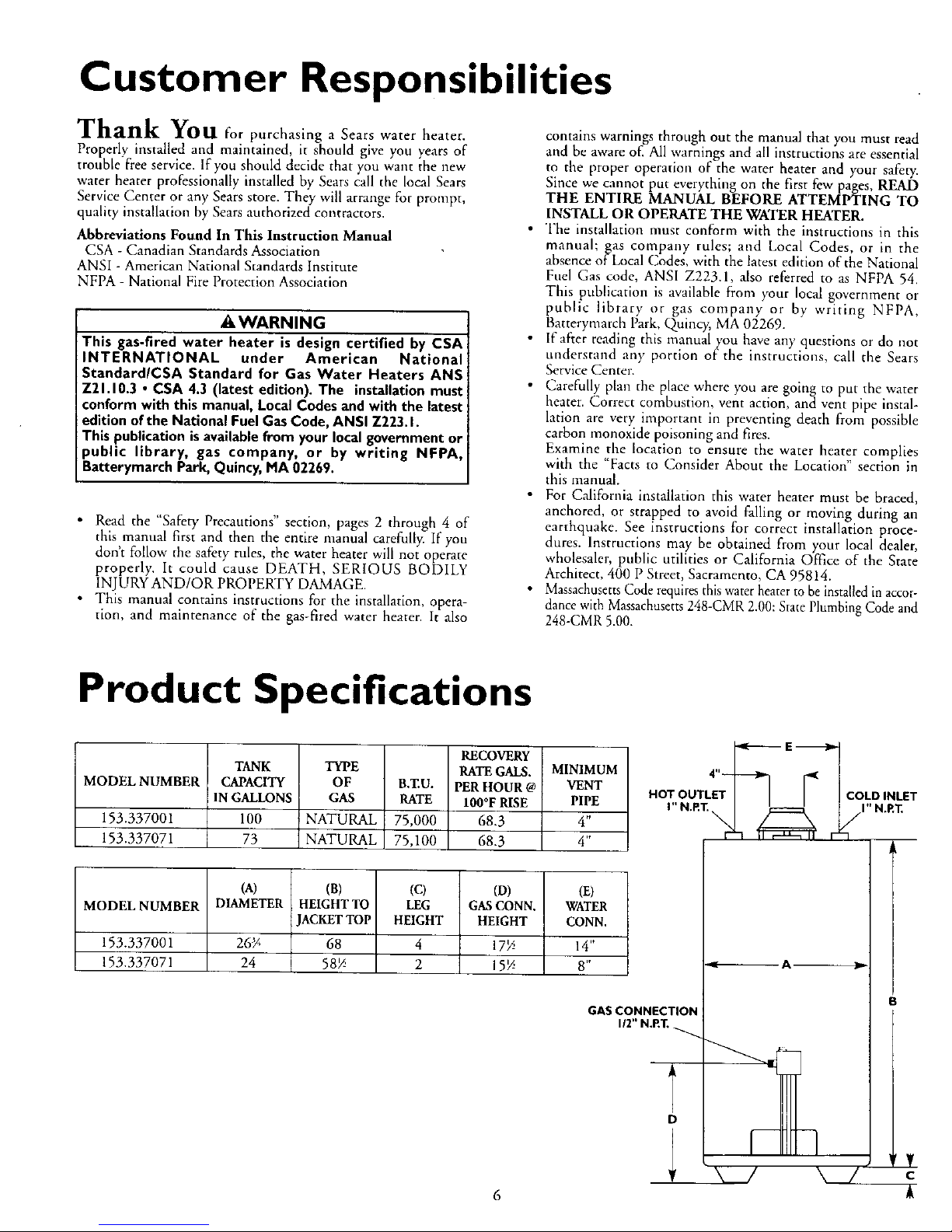
Product Specifications
MODEL NUMBER
153.337001
153.337071
TANK
CAPACITY
IN GALLONS
100
73
RECOVERY
TYPE RATE GALS.
OF B,T.U. PER HOUR @
GAS RATE 100°F RISE
NATURAL 75,000 68.3
NATURAL 75,100 68.3
MINIMUM
VENT
PIPE
4"
4"
(A) (B) (C) (D) (El
MODEL NUMBER DIAMETER HEIGHT TO LEG GASCONN. WATER
JACKETTOP HEIGHT HEIGHT CONN.
153.337001 26_ 68 4 17> 14"
153.337071 24 58> 2 15> 8"
GAS CONNECTION
112"N.P.T.
i_ E
HOT OUTLE COLDINLET
D
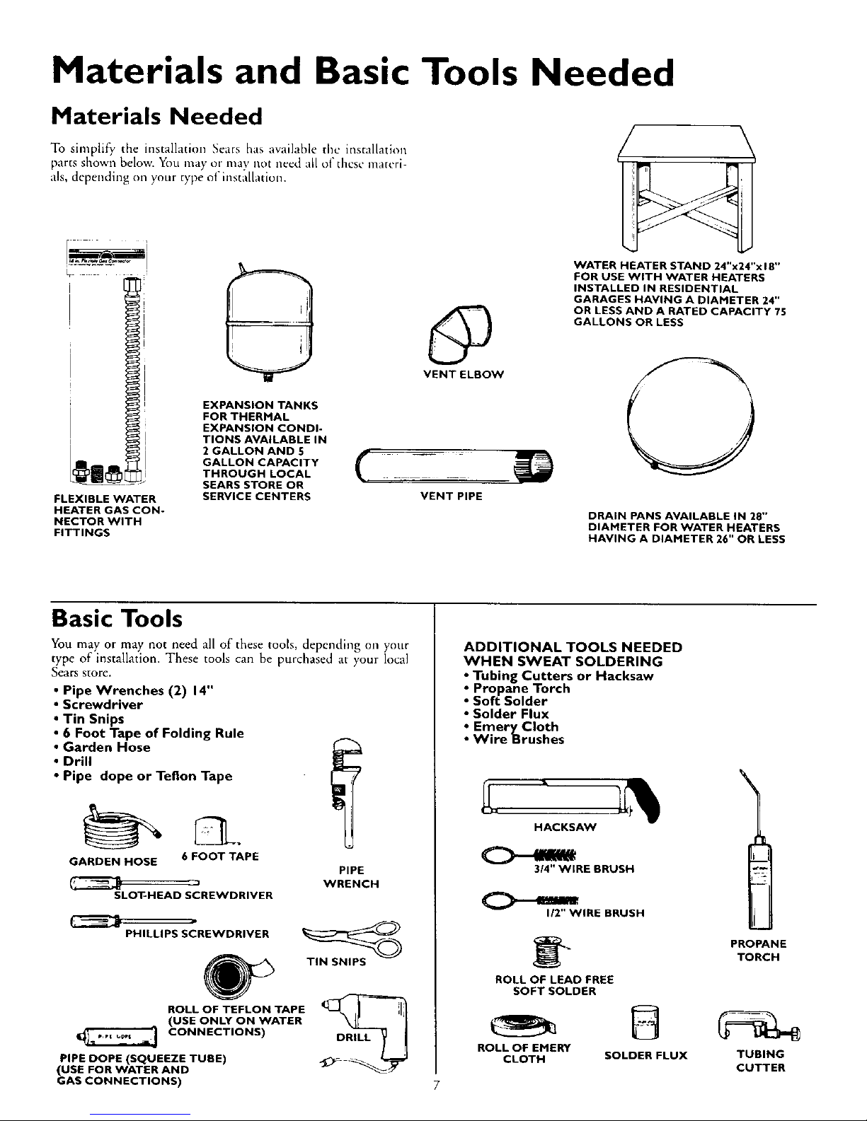
Materials and Basic Tools Needed
Materials Needed
To simplify the installation Seats has available the installation
)arts shown below. You may i)[ illay IlOt need all of these materi
ills, depending on your type o['insta[[atiotl.
i
J
FLEXIBLE WATER
HEATER GAS CON-
NECTOR WITH
FITTINGS
0
EXPANSION TANKS
FOR THERMAL
EXPANSION CONDI-
TIONS AVAILABLE IN
2 GALLON AND 5
GALLON CAPACITY
THROUGH LOCAL
SEARS STORE OR
SERVICE CENTERS
@
VENT ELBOW
WATER HEATER STAND 24"x24"x 18"
FOR USE WITH WATER HEATERS
INSTALLED IN RESIDENTIAL
GARAGES HAVING A DIAMETER 24"
OR LESS AND A RATED CAPACITY 75
GALLONS OR LESS
O
DRAIN PANS AVAILABLE IN 28"
DIAMETER FOR WATER HEATERS
HAVING A DIAMETER 26" OR LESS
Basic Tools
You may or may not need all of these tools, depending on your
type of installation. These tools can be purchased at your local
Sears store.
Pipe Wrenches (2) 14"
Screwdriver
Tin Snips
6 Foot Tape of Folding Rule
Garden Hose
Drill
• Pipe dope or Teflon Tape
GARDEN HOSE 6 FOOT TAPE
3
SLOT-HEAD SCREWDRIVER
PIPE
WRENCH
PHILLIPS SCREWDRIVER
ROLL OF TEFLON TAPE
(USE ONLY ON WATER
CONNECTIONS)
PIPE DOPE (SQUEEZE TUBE)
(USE FOR WATER AND
GAS CONNECTIONS)
TIN SNIPS
ADDITIONAL TOOLS NEEDED
WHEN SWEAT SOLDERING
• Tubing Cutters or Hacksaw
• Propane Torch
• Soft Solder
• Solder Flux
• Emery Cloth
• Wire Brushes
HACKSAW
314" WIRE BRUSH
O--'"
112"WIRE BRUSH
_ PROPANE
TORCH
ROLL OF LEAD FREE
SOFT SOLDER
ROLL OF EMERY
CLOTH SOLDER FLUX TUBING
CUTTER
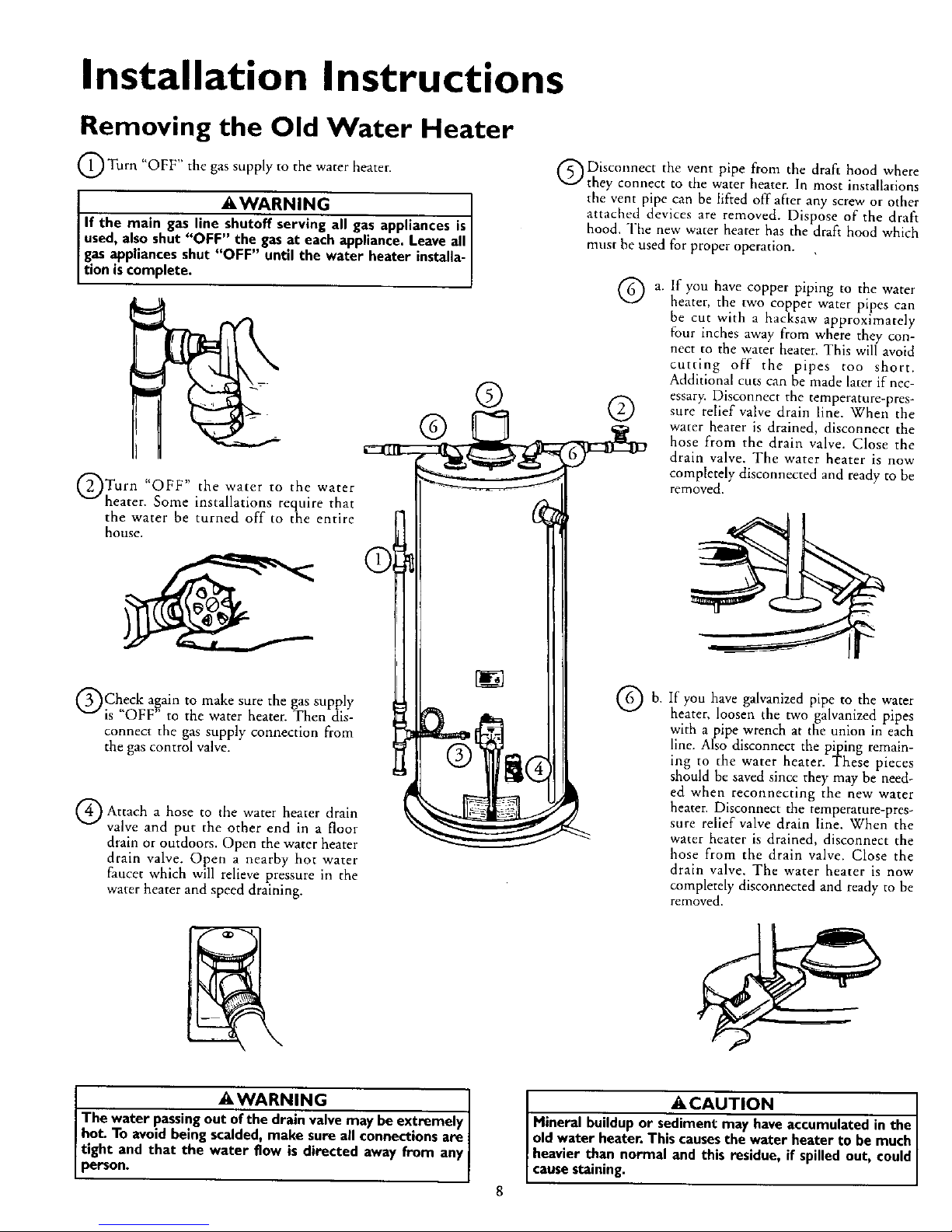
Installation Instructions
Removing the Old Water Heater
O Turn "OFF" the gas supply to the water heater.
_,WARNING
If the main gas line shutoff serving all gasappliances is
used,alsoshut "OFF" the gasat eachappliance.Leave all
gas appliances shut "OFF" until the water heater installa-
tion is complete.
Turn water to water
"OFF" the the
heater. Some installations require that
the water be turned off to the entire
house.
Check again to make sure the gas supply
is "OFF" to the water heater. Then dis-
connect the gas supply connection from
the gas control valve.
Attach hose the heater drain
a
to water
valve and put the other end in a floor
drain or outdoors. Open the water heater
drain valve. Open a nearby hot water
faucet which will relieve pressure in the
water heater and speed draining.
@Disconnect the vent pipe from the draft hood where
they connect to the water heater. In most installations
the vent pipe can be lifted off after any screw or other
attached devices are removed. Dispose of the draft
hood. The new water heater has the draft hood which
must be used for proper operation.
®
® @
©
If you have copper piping to the water
heater, the two co[3per water pipes can
be cut with a hacksaw approximately
four inches away from where they con-
nect to the water heater. This will avoid
cutting off the pipes too short.
Additional cuts can be made later if nec-
essary. Disconnect the temperature-pres-
sure relief valve drain line. When the
water heater is drained, disconnect the
hose from the drain valve. Close the
drain valve. The water heater is now
completely disconnected and ready to be
removed.
Qb.
If you have galvanized pipe to the water
heater, loosen the two galvanized pipes
with a pipe wrench at the union in each
line. Also disconnect the piping remain-
ing to the water heater. These pieces
should be saved since they may be need-
ed when reconnecting the new water
heater. Disconnect the temperature-pres-
sure relief valve drain line. When the
water heater is drained, disconnect the
hose from the drain valve. Close the
drain valve. The water heater is now
completely disconnected and ready to be
removed.
I _,WARNING
The water passingout of the drain valvemay be extremely I
hot. To avoid beingscalded,make sure all connectionsare
tight and that the water flow is directed away from any
person.
•_CAUTION
Hineral buildup or sediment may haveaccumulatedin the
oldwater heater. This causesthe water heater to bemuch
heavier than normal and this residue, if spilledout, could
causestaining.
Installation Instructions (cont'd)
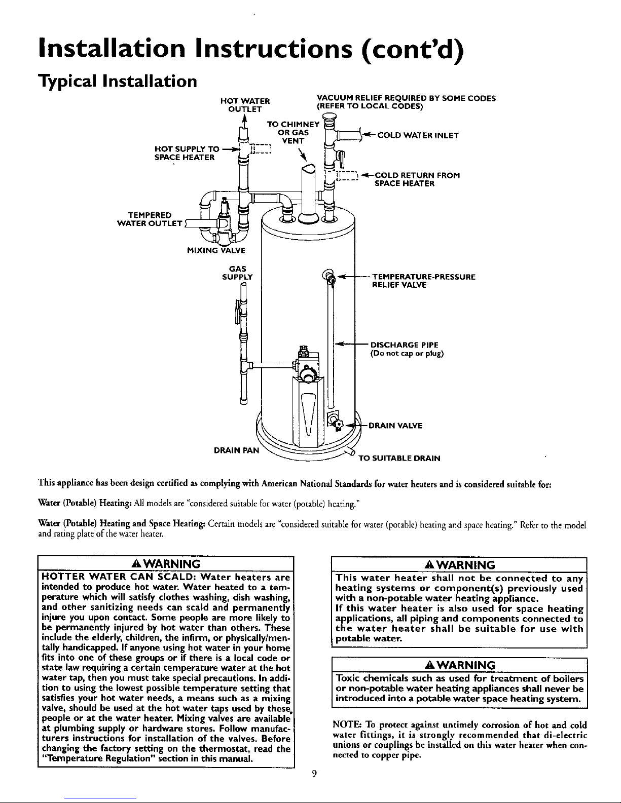
Typical Installation
HOT WATER
OUTLET
VACUUM RELIEF REQUIRED BY SOME CODES
(REFER TO LOCAL CODES)
HOT SUPPLY TO ---_
SPACE HEATER
wTTEMRPoERuEDLET _
MIXING VALVE
TO CHIMNEY
OR GAS
VENT
GAS
SUPPLY
-K-- COLD WATER INLET
--'_€--COLD RETURN FROM
SPACE HEATER
-- TEMPERATURE-PRESSURE
RELIEF VALVE
-- DISCHARGE PIPE
(Do not cap or plug)
-DRAIN VALVE
DRAIN PAN
TO SUITABLE DRAIN
This appliance has been designcertifiedas complying with American National Standards for waterheaters and is consideredsuitable for:
Water (Potable)Heating:All modelsare "consideredsuitablefor water(potable)heating."
Water (Potable)Heating and Space Heating: Certain modelsare "consideredsuitablefor water(potable)heatingand space heating." Referto the model
and ratingplate of the waterheater.
AWARNING
HOTTER WATER CAN SCALD: Water heaters are
intended to produce hot water. Water heated to a tem-
perature which will satisfy clothes washing, dish washing,
and other sanitizing needs can scald and permanently
injure you upon contact. Some people are more likely to
be permanently injured by hot water than others. These
include the elderly, children, the infirm, or physicallylmen-
tally handicapped. If anyone using hot water in your home
fits into one of these groups or if there is a local code or
state law requiring a certain temperature water at the hot
water tap, then you must take special precautions. In addi-
tion to using the lowest possible temperature setting that
satisfies your hot water needs, a means such as a mixing
valve, should be used at the hot water taps used by these.
people or at the water heater. Mixing valves are available
at plumbing supply or hardware stores. Follow manufac-
turers instructions for installation of the valves. Before
changing the factory setting on the thermostat, read the
"Temperature Regulation" section in this manual.
AWARNING
This water heater shall not be connected to any
heating systems or component(s) previously used
with a non-potable water heating appliance.
If this water heater is also used for space heating
applications, all piping and components connected to
the water heater shall be suitable for use with
potable water.
AWARNING
Toxic chemicals suc_reatment of boilers
or non-potable water heating appliances shall never be
introduced into a potable water space heating system.
NOTE: To protect against untimely corrosion of hot and cold
water fittings, it is strongly recommended that di-electric
unions or couplings be installed on this waterheater when con-
nected to copper pipe.
Installation Instructions (cont'd)
Facts to Consider About the
Location
You should carct:ully choose an indoor location t_l tllc new
water heater, because the placement is a very ilnportant consid-
eration for the saI_.'tv of" the occupants in the building and f_+,
tile most economical use of the appliance. This water heater is
not for use in mobile homes or outdoor installation.
Whether replacing an old water heater or rotting the water
hea_er in a new location, tile f_31h_winR critical points must be
observed.
• The location selected should bc indoors as close as practical to
the gas vent or chimney to which the water heater vent is
going m bc connected, and as centralized with tile wa_cr pip-
ing system as possible. Ihc water heater, as all water heatcta,
will eventually leak. Do not install without adequate drainage
provisions where water flow will cause damage
A CAUTION
WATER HEATERS EVENTUALLY LEAK: Installation of the
water heater most be accomplished in such a manner that if
the tank or any connections should leak, the flow of water will
not cause damage to the structure. For this reason, it is not
advisableto installthe water heater in an attic or upper floor.
When such locations cannot be avoided, a suitable drain pan
should be installed under the water heater. Drain pansare avail-
able at your local Sears store. Such a drain pan must be not
greater than I _ inches deep, have a minimum length and width
of at least 2 inches greater than the water heater dimensions
and must be piped to an adequate drain. The pan must not
restrict combustion air flow. Under no circumstances is the
manufacturer or Sears to be held liable for any water damage
in connection with this water heater
AWARNING
INSTALLATIONS IN AREAS WHERE FLAMMABLE LIQUIDS
(VAPORS) ARE LIKELY TO BE PRESENT OR STORED
(GARAGES, STORAGE, AND UTILITY AREAS, ETC):
Flammable liquids(such as gasoline, solvents, propane (LP) or
butane, etc.), all of which emit flammable vapors, may be
improperly stored or used in such areas. The gas water heater
pilot light or main burner can ignite suchvapors. The resulting
flashbackand fire can causedeath or seriousburns to anyone in
the area, aswell asproperty damage.
If installationin suchareas is your only option, then the installa-
tion must be accomplished in a way that the pilot flame and
main burner flame are elevated from the floor at least 18inches.
While this may reduce the chancesof flammable vapors from a
floor spillbeingignited, gasoline and other flammable substances
should never be stored or usedin the same room or area con-
raininga gas water heater or other open flame or spark produc-
ing appliance.
NOTE: Flammable vapors may be drawn by air currents from
other areas of the structure to the appliance.
AWARNING
Propellants of aerosol sprays and volatile compounds, (clean-
ers, chlorine based chemicals, refrigerants, etc.) in addition to
being highly flammable in many cases, will also change to cor-
rosive hydrochloric acid when exposed to the combustion
products of the water heater. The results can be hazardous,
and also cause product failure.
• IJle tocacion selection illllst provide adequate clearances for ser-
vicing and proper openttion ofthe water heater.
_,WARNING
This water heater must not he installed directly on carpeting.
Carpeting must be protected by a metal or wood panel
beneath the appliance extending beyond the full width and
depth of the appliance by at least 3 inches (76.2mm) in any
direction, or if the appliance isinstalled in an alcove or closet, I
the entire floor must be covered by the panel. Failure to heed
this warning may result in a fire hazard.
_kWARNING
Minimum clearances between the water heater and com-
bustible construction are I" at the sides and rear, 4" at the
!front, and 6 from the vent pipe. Clearance from the top of the
=jacket is 18" on most models. Note that a lesserdimension may
be allowed on some models. Refer to the label on the water
I heater adjacent to the gascontrol valve for allclearances.
AWARNING
A gas water heater cannot operate properly without the cor-
rect amount of air for combustion. Do not install in a confined
area sucha closet, unlessyou provide air as shown in the "Facts
to Consider About the Location" section. Never obstruct the
flow of ventilation air Ifyou have any doubtsor questions at all,
call your gascompany. Failure to provide the proper amount of
combustion air can result in a fire or explosion and can cause
DEATH, SERIOUS BODILY INJUI_, OR PROPERTY DAMAGE.
_,WARNING
If this water heater will be used in beauty shops,barber shops,
cleaning establishments, or self-service laundries with dry
cleaning equipment, it is imperative that the water heater or
water heaters be installed so that combustion and ventilation
air be taken from outside these areas. Refer to the "Facts to
Consider About the Location section of this manual and also
the latest edition ofthe National Fuel Gas Code, ANSI Z223.1,
also referred to as NFPA 54 for specificsprovided concerning
air required,
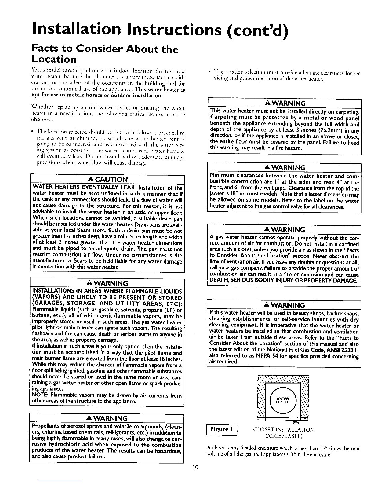
Figure I I
CI,OSET INSTALLATION
(ACCEPTABLE)
A closet is any 4 sided enclosurewhich is less than 16=times the total
volumeof allthe gas firedapplianceswithin the enclosure.
10

Installation Instructions (cont'd)
Facts to Consider About the
Location (cont'd)
Combustion Air and
Ventilation for Appliances
Located in Unconfined Spaces
Unconfined Space is a space whose volume is not less than 50
cubic feet per l,O00 Btu per hour of the aggregate input rating
of all appliances installed in that space. Rooms communicating
directly with the space in which the appliances are installed,
through openings nor furnished with doors, are considered a
part of the unconfined space
Figure 2 ]
ROOM INSTALLATION
/ACCEPTABLE)
A room is any enclosure which is at least 16" times
greater than the total volume of all the gas fired appli-
ances within the enclosure.
In unconfined spaces in buildings, infiltration may be adequate
to provide air for combustion, ventilation and dilution of flue
gases. However, in buildings of tight construction (for example,
weather stripping, heavily insulated, caulked, vapor barrier, etc.),
additional air may need to be provided using the methods
described in Combustion Air and Ventilation for Appliances
Located in Confined Spaces, b.
Figure 3 ]
ALCOVEINSTALLATION
(ACCEPTABLE)
An alcove suitable for the installation of awater heater is a
restricted section of a room not separated from the room
by a door or partition and which meets the minimum
clearances for the specific model water heater listed
below.
*When the ceiling height exceeds 8 feet, you are only
allowed to consider 8 feet when calculating the total vol-
ume of the enclosure.
12" MAX.
- _
VENTILATION
AIR
OPENINGS O
DOOR
FRONT VIEW
OF DOOR
[Figure ]
12" MAX
_l _" MIN.
AIR DUCT
[Figure j
_iWARNING
Minimum clearances between the water heater and
combustible construction are listed below:
Minimum Side & Rear Clearances -- r'
Minimum front clearance from jacket to closet door -- 4"
Minimum ceiling clearance from jacket top to com-
bustible ceiling -- 18",
Combustion Air and
Ventilation for Appliances
Located in Confined Spaces
Confined Space is a space whose volume is less than 50 cubic
feet per 1,000 Btu per hour of the aggregate input rating of all
appliances installed in that space.
a, ALL AIR FROM INSIDE BUILDINGS:
(See Figures lrhrough 6)
Tbe confined space shall be provided with two permanent
openings communicating directly with an additional room(s)
of sufficient volume so that the combined volume of all
spaces meets the criteria for an unconfined space. The total
input of all gas utilization equipment installed in the com-
bined space shall be considered in making this determination.
Each opening shall have a minimum free area of one square
inch per 1,000 BTU per hour of the total input rating of all
gas utilization equipment in the confined space, but not less
than 100 square inches. One opening shall commence within
12 inches of the top and one commencing within 12 inches
of the bottom of the enclosure.
Figure 6 ]
S VENT
II
b. ALL AIR FROM OUTDOORS: (see Figures 7 through 9,
page 12)
The confined space shall be provided with two permanent
openings, one commencing within 12 inches of the top and
one commencing within 12 inches from the bottom of the
enclosure. The openings shall communicate directly, or by
ducts, with the outdoors or spaces (crawl or attic) that freely
communicate with the outdoors.

Installation Instructions (cont'd)
Combustion Air and
Ventilation for Appliances
Located in Confined Spaces (cont'd)
Figure 7 ]
CHlUNEY O_ GAS VENT
V_NTILATION LOUVERS
(each end of a_,c)
WATER HEATER
.FURNACE
At.T INLET_IR VE_CTILATIONLOUVERS
1. When directly communicating with the outdoors, each open-
ing shall have a minimum free area of 1 square inch per 4,000
BTU per hour of coral input rating of all equipment in the
endosure. (See Figure 7.)
2. When communicating with the outdoors through vertical
ducts, each opening shall have a minimum free area of 1
square inch per 4,000 BTU per hour of total input rating of
all equipment in the enclosure. (See Figure 8.)
Figure 8 !
_CHIMNEY OR GAS VENT
VENTILATION LOUVERS
{each end ol _t_ I
WATEN HEATER
FURNACE
INLET AIR DUCT
above floor)
ZI I I
3. When communicating with the outdoors through horizontal
ducts, each opening shall have a minimum free area of 1
square inch per 2,000 BTU per hour of total input rating of
all equipment in the enclosure. (See Figure 9.)
Figure 9 ]
CHIMNEY OR GAS VEI
_ OUTLET AIFt OklCT
-- INLET AIR DUCT
4. When ducts are used, they shall be of the same cross-sectional
area as the free area of the openings to which they connect.
The minimum short side dimension of rectangular air ducts
shall not be less than 3 inches. (See Figure 9.)
5, louvers and (;rillcs: In calctilatin_ l:ree area, co[lside,ation
shall he given to the blocking ef(_'ct of louvers, grilles or
screens m3te,_tin_ openings. Screens used shah not bc smaller
than I/. itlch n'_esrJ. If the flee area through a design of louver
or grille is known, it should be used in calculating the size
(H_ening requ0-ed to provide the free area specified. If the
dcslgu and fice area is not kllown, it may be assumed that
wood louvers will h_ 20 25 percent t_ec area and metal louvers
and grilles \viii ]lave 60-75 percent free area. Louvers and
grilles shall be fixed in the open position or interlocked with
the equipment so that they arc opened automatically during
equipment operation.
6. Special (]onditions Created hy Mechanical Exhausting or
Fireplaces: Operation of exhaust leans, ventilation systems,
clothes dryers or fireplaces may create conditions requiring
special attenthm m avoid unsatisfactory operation of installed
gas utilization equipment.
Water Piping
AWARNING
HOTTER WATER CAN SCALD; Water heaters are intended to
produce hot water. Water heated to a temperature which will
satisfyclothes washing,dish washing,and other sanitizing needs
can scald and permanently injure you upon contact. Some peo-
pleare more likelyto be permanently injured byhot water than
others. These includethe elderly,children, the infirm, or physical-
ly/mentally handicapped. If anyone using hot water in your home
fits into one of thesegroupsor ifthere isa localcode or state law
requiring a certain temperature water at the hot water tap, then
,ou must take specialprecautions.In additionto usingthe lowest
mssibletemperature setting that satisfiesyour hot water needs,
a means such as a mixing valve, shouldbe usedat the hot water
taps used by these people or at the water heater. Mixing valves
are available at plumbingsupplyor hardware sto_s. Follow man-
ufacturers instructions for installation of the valves. Before
changing the factory setting on the thermostat, read the
"Temperature Regulation" sectioninthis manual.
This water heater shall not be connected to any heating systems
or component(s) used with a non-potable water heating
appliance.
If a water heater is installed in a closed water supply system; such as
one having a back flow preventer, check valve, water meter with a
check valve, etc.., ill the cold water supply; means shall be provided
to control thermal expansion. Contact the local utility or local Sears
Service Cemer oil how to control this situation.
NOTE: To protect against untimely corrosion of hot and
cold water fittings, it is strongly recommended that di-elec-
tric unions or couplings be installed on this water heater
when connected to copper pipe.
NOTE: If using copper tubir, g, solder tubing to an adapter
before attaching the adaptor to the cold water inlet connection.
Do not solder the cold water supply line direcdy to the cold
water inlet. It will harm the dip tube and damage the tank.
12

Installation Instructions (cont'd)
Temperature-Pressure Relief Valve
_, WARNING
At the time of manufacture this water heater was provided
with a combination temperature-pressures relief valve certi-
fied by a nationally recognized testing laboratory that main-
tains periodic inspection of production of listed equipment or
materials, as meeting the requirements for Relief Valves and
Automatic Gas Shutoff Devices for Hot Water Supply
Systems, and the latest edition of ANSI Z21.22 and the code
requirements of ASME. tf replaced, the valve must meet the
requirements of local codes, but not less than a combination
temperature and pressure relief valve certified as meeting
the requirements for Relief Valves and Automatic Gas
Shutoff Devices for Hot Water Supply Systems, ANSI Z21.22
by a nationally recognized testing laboratory that maintains
periodic inspection of production of listed equipment or
materials.
The valve must be marked with a maximum set pressure not
to exceed the marked hydrostatic working pressure of the
water heater (150 Ibs./sq. in.) and a discharge capacity not
lessthan the water heater input rate as shown on the model
rating plate. (Electric heaters - watts divided by 1000 x 3415
equal BTU/Hr. rate.)
Your local jurisdictional authority, while mandating the use of
a temperature-pressure relief valve complying with ANSI
Z21.22 and ASHE, may require a valve model different from
the one furnished with the water beater.
Compliance with such local requirements must be satisfied
by the installer or end user of the water heater with a locally
prescribed temperature-pressure relief valve installed in the
designated opening in the water heater in place of the facto-
ry furnished valve.
For safe operation of the water heater, the relief valve must
not be removed from it's designated opening or plugged.
The temperature-pressure relief valve must be installed
directly into the fitting of the water beater designated for the
relief valve. Position the valve downward and provide tubing
so that any discharge will exit only within 6 inches above, or
at any distance below the structural floor. Be certain that no
contact is made with any live electrical part. The discharge
opening must not be blocked or reduced in size under any
circumstances. Excessive length, over 15 feet, or use of more
than two elbows can cause restriction and reduce the dis-
charge capacity of the valve.
No valve or other obstruction is to be placed between the
relief valve and the tank. Do not connect tubing directly to
discharge drain unless a 6" air gap is provided. To prevent
bodily injury, hazard to life, or property damage, the relief
valve must be allowed to discharge water in quantities should
circumstances demand. If the discharge pipe is not connect-
ed to a drain or other suitable means, the water flow may
causeproperty damage.
The Discharge Pipe:
Must not be smaller in size than the outlet pipe size of the
valve, or haveany reducing couplings or other restrictions.
Hust not be plugged or blocked.
Must be of material listed for hot water distribution.
Must be installed soas to allow complete drainage of both
the temperature-pressure relief valve, and the discharge
pipe.
• Must terminate at an adequate drain.
• Must not have any valve between the relief valve and tank.
13
_,WARNING
The temperature-pressure relief valve must be manually
operated at least once a year. Caution should be taken to
ensure that (I) no one is in front of or around the outlet of
the temperature-pressure relief valve discharge line, and (2)
the water manually discharged will not cause any bodily
injury or property damage because the water may be
extremely hot.
If after manually operating the valve, it fails to completely
reset and continues to release water, immediately close the
cold water inlet to the water heater, follow the draining
instructions, and replace the temperature-pressure relief
valve with a new one.
_t, WARNING
If a water heater is installed in conjunction with a sep-
arate storage vessel, the storage vessel must also be
equipped with a temperature-pressure relief valve
complying with the Standard for Relief Valves and Hot
Water Supply Systems, ANSI Z21.22. The hourly
rated temperature steam BTU discharge capacity of
the temperature-pressure relief valve(s) shall not be
less than the combined BTU input of the water
heater(s) supplying water to the storage vessel(s).
HOT _ COLD
SHUTOFF
VALVE
PRESSURE
RELIEFVALVE
DISCHARGE PIPE
[] (Do not cap or plug)
At the time of manufacture, this water heater was provided with a combination tem-
perature-pressure relief valve listed as complying with the standard for relief valves
and automabe gasshut-off devices for hot water supply systems, ANSI Z21.22. For
safeoperation of the water heater,the relief valve must not be removed from its des-
ignated point of installation or plugged.
Your local jurisdictiona_ authority, while mandating the use of a temperature-pressure
relief valve complying with ANSI Z2122 and ASME. may require a valvemodel differ-
entfrom the one furnished with the water heatem
Compliance with such local requirements musebesatisfied by the installer or end user
of the water heater with a locally prescribed temperature-pressure relief valve
installed in the designated opening in the water heated
See manual heading -"Temperature-Pressure Relief Valves" for installationand mainte-
nance of relief valve, discharge line, and other safety precautions.
RELIEFVALVEOPENING

Installation Instructions (cont'd)
Filling the Water Heater
ACAUTION
Never use this water h_ completely filled with
water. To prevent damage to the tank, the tank must be filled
with water. Water must flow from the hot water faucet
before turning "ON" gas to the water heater.
To fill the water heater with water:
Close the water heater drain valve by' turning the handle to
the right (clockwise). The drain valve is on the lower front of
the water heater.
Open the cold water supply valve to the water heater.
NOTE: The cold water supply valve must be left open
when the water heater is in use.
• To insure complete filling of the tank, allow air to exit by
opening the nearest hot water faucet. Allow water to run
until a constant flow is obtained. This will let air out of the
water heater and the pipir_g.
• Check all new water piping for leaks. Repair asneeded.
AWARNING
To insure proper venting of this gas-fired water heater, the
correct vent pipe diameter must be utilized. Any additions or
deletions of other gas appliances on a common vent with this
water heater may adversely affect the operation ofthe water
heater. Consult the local Sears Service Center or gas utility if
any suchchangesare planned.
For proper venting in certain installations, a larger diameter vent
pipe may be necessary. Due to great variances in installations,
unforeseeable by the manufacturer of the water heater, you must
consult your gas company to aid you in determinin_ tile pro)er
venth'l_ _oryour water beater from the vent tables in the latest edi-
don otthe National Fuel Gas Code ANSI Z223.1, also referred to
as NFPA 54.
Check the venting system for signs of obstruction or deterioration
and replace if needed.
The combustion and ventilation air flow must nor be obstructed.
Venting
TO CHIMNEY
PLACE
_ PROVIDED
L_GS
IN HOLES
The draft hood supplied with this water heater must be instalted as
shownbeforethe heater is operated.
If the draft hood is removed for cleaning or replacement it must be
replaced in reverse order as removed.
AWARNING
VENT DAMPERS - Any vent damper, whether it is operated
thermally or otherwise must be removed if its useinhibits prep-
er drafting of the water heater.
Thermally Operated Vent Damper_ Gas-fired water heaters
having thermal efficiency in excessof 80% may produce a rela-
tively low flue gastemperature. Such temperatures may not be
high enough to properly open thermally operated vent
dampers. This would causespillage of tlue gasesand may cause
carbon monoxide poisoning.
Vent dampers must bear evidence of certification as complying
with the latest edition of American Natlonal Standard ANSI
Z21.68 (ANSI Z21,66 & 67, respectively, cover electrically and
mechanically actuated vent dampers), Before installation of any
vent damper, consult yourlocal Sears Service Center or the gas
utility for further information.
AWARNING
Obstructed or deteriorated vent systemsmay present a serious
health risk or asphyxiation.
AWARNING ]
The water heater wit_talled must be properly/
vented to a chimney which terminates outdoors. Never oper-|
ate the water heater unlessit isvented to the outdoors and has|
adequate air supplyto avoidrisksof improper operation, explo-|
sionor asphyxiation. |
AWARNING
The vent pipe from thewater heatermustbe no lessthanthe [
diameter of the draft hoodoutlet on the water heater,andI
must slopeupwardto the chimneyat least ¼ inchper linear
foot. [
All vent gases must be completely vented to the outdoors, of the.
structure (dwelling). Install only the draft hood provided with
the new water heater and no other draft hood.
Vent pipes must be secured at each joint with sheet metal screws.
T°
CHIMNEY
1
VENT PIPE INSTALLATION
14

Installation Instructions (cont'd)
Venting (cont'd)
There must be a mininmln of 6" clearance between single wall
vent pipe and any combustible material. Fill and seal ;iny clcaI-
ancc between single wall vent pipe and combustible material
with mortar mix, c_n_cllt, or ()tiler noncombustible substance.
For other than single wall, follow vent pipe manufacturer's clear-
ance specifications. To insure a tight'fit of the ,,,_entpipe in a
brick chimney, seal around the vent pipe with mortar mix
ccmenL
AWARNING
Minimum clearances between the water heater and com-
bustible construction are I" at the sides and rear, 4" at the
front, and 6" from the vent pipe. Clearance from the top ofthe
jacket is 18" on most models. Note that a lesserdimension may
be allowed on some models. Refer to the label on the water
heater adjacent to the gascontrol valve for all clearances.
AWARNING
Failure to have required clearances between vent piping and
combustible material will result in a fire hazard.
Where an exhaust fan is installed in the same room as the
water heater, air will be drawn into the room through the
chimney. Air supply openings must be large enough to admit
air exhausted by th'e fan and that required'by all gasburning
appliances. A down-draft or back-draft will prevent pro)er
combustion, causing soot which may result in seriousdamage
to the water heater.
Where continuous or intermittent backdraft is found to exist,
check chimney conditions, in some casesa blower ty)e flue
gasexhauster must be employed between the a)pliance and
the stackto assureproper vent ng and correct combustion.
Combining vents as shown below issatisfactory, providing the
basic rules of good venting are observed. In either case, the
vertical rise above draft hood (X) before any fittings, should be
asgreat as possible. All venting connections should be made
in accordance w th oca codes and ordinances.
When vents are combined, area of the combined vent
should be equal to area of the largest single vent, plus 50"/,,
of area of all others joining it.
EXAMPLE: To combine two 6" vents with an 8" vent, the
area of a combined vent should be one half
area of two 6" vents (14+14) plus area of 8"
vent (50) = 78 sq. inches. Referring to chart, 78
sq. inches requires a 10' diameter vent.
VENT SQUARE
SIZE INCHES
5" 20
6" 28
7" 38
8" 50
9" 64
VENT SQUARE
SIZE INCHES
10" 79
12" 113
14_' 154
16" 201
18" 254
AWARNING
A gas water heater cannot operate properly without the cor-
rect amount of air for combustion. Do not install in a confined
area such a closet, unlessyou provide air asshown in the "Facts
to Consider About the Location" section. Never obstruct the
flow of ventilation air. If you have any doubts or questions at all
ca your gascompany. Failure to provide the proper amount of
combustion air can result in a fire or explosion and can cause
DEATH, SERIOUS BODILY INJUR_, OR PROPERTY DAMAGE.
AWARNING -]
Be sure vent pipe isproperly connected to prevent escape of I
dangerous flue gaseswhich could causedeadly asphyxiation. J
AIWARNING
Chemical vapor corrosion of the flue and vent system may
occur if air for combustion contains certain chemical vapors.
Spray can propellants, cleaning solvents, refrigerator and air
conditioner refrigerants, swimming pool chemicals, calcium
and sodium chloride, waxes, bleach, and processchemicals are
typical compounds which are potentially corrosive.
Gas Piping
_,WARNING
Make sure the gas supplied is the same type listed on the
model rating plate. The inlet gas pressure must not exceed
10.5 inches water column (2.6kPa) for Natural Gas and 13
inches water column (3.5kPa) for Propane (L.R) Gas. The
minimum inlet gas pressure listed on the model rating plate
isfor the purpose of input adjustment.
•,WARNING , J
If the gas control valve is subjected to pressures exceeding ½ J
pound per square inch (3.5kPa), the damage to the gascon-
trol valve could result in a fire or explosion from eak ng gas.
15
_,WARNING I
If the main gas line shutoffservingall gasappliancesis used,
alsoturn "OFF" the gasateachappliance.Leaveallgasappli-
ancesshutoffuntil the water heater installationiscompete.

Installation Instructions (cont'd)
Gas Piping (cont'd)
CORRECT GAS PIPE SIZE FOR
WATER HEATERS OPERATING ON NATURAL GAS
BasedonInletGasPressuresof0.5psigor Lessand
a PressureDrop of 0.3inchesWater Column.
(Basedbna0.60SpecificGravityGas)
TOTAL INPUT* DISTANCE TO METER, IN FEET
BTU/HR 20 30 60 90 125 150 200
75,000 '/2 3/4 3/4 3/4 I I I
100,000 % 3/4 3/4 I I I I
150,000 314 314 I I I'14 174 I%
*OlCallgas appliances in line.
A gas line of sufficient size must be run to the water heater.
Consult the latest edition of National Fuel Gas Code ANSI
Z223.1, also referred to as NFPA 54 and the gas company con-
cerning pipe size.
There must be:
• A readily accessible manual shut off valve in the gas supply line
serving the water heater, and
• A drip le{{(sediment trap) ahead of the gas control valve to help
prevent dirt and foreign materials from entering the gas control
Valve,
• A flexible gas connector or a ground joint union between the
shutoffvalve and control valve to permit servicing of the unit.
Be sure to check all the gas piping for leaks before lighting the
water heater. Use a soapy water solution, not a match or open
flame. Rinse offsoapy solution and wipe dry.
Standard Models are for installation up to 3,300 feet above sea
level.
High Altitude Models are for installation from 3,300 to 5,500 feet
above sea level.
Ifa standard model is installed above 3,300 feet or a high altitude
models is installed above 5,500 feet, the input rating must be
reduced at the rate of 4 percent for each 1,000 feet above sea level.
Contact your local Sears Service Center or gas utility for further
information.
_,WARNING I
The applianceand its gas connection must be leak tested
beforep acngtheapp ancein operation.
_,WARNING
• The appliance and its individual shutoff valve must be discon-
nected from the gas supplypipingsystem during any pressure
testing of the gas system at test pressures in excess of ½
poundper square inch (3.5kPa).
• The appliance must be isolated from the gassupplypiping sys-
tem by closingits individual manual shutoff valve during any
pressuretesting of the gassupply piping system at test pres-
suresequal or lessthan ½ pound per square inch (3.5kPa).
_,WARNING l
Use pipe joint compound or teflon tape marked as beingI
resistantto the actionof potro eum [Propane(I-R)] gases. I
16
GAS PIPING WITH
FLEXIBLE CONNECTOR
GAS SUPPLY PIPING
MANUAL _
SHUTOFF
VALVE
FLEXIBLEGAS CONNECTOR
LABELEDAS COMPLYING
WITH ANSI STANDARDS
GROUND JOINT _ ,&_ LOOP _
UNION (Optional) _ N _
_' _ CONTROL
T VALVE
3-_IN,_ _LEGtFap) _.I
GAS PIPING WITH _,LL BLACK IRON
PIPE TO GAS CONTROL
MANUAL _GAS SUPPLYPIPING
SHUTOFF
VALVE
BLACKPIPE
GROUND
3" MIN. DRIP LEG
(Sediment trap)
GAS
CONTROL
VALVE
AWARNING
Contaminants in the gaslines may cause improper operation
of the gas control valve that may result in fire or explosion.
Before attaching the gas line be sure that all gas pipe isclean
on the inside. To trap any dirt or foreign material in the gas
supply line, a drip leg (sometimes called a sediment trap)
must be incorporated in the piping. The drip leg must be
readily accessible. Install in accordance with the "Gas Piping"
section. Refer to the latest edition of the National Fuel Gas
Code, ANSI Z223.1, also referred to as NFPA 54.

Installation Instructions (cont'd)
Installation Checklist
BEFORE LIGHTING THE PILOT:
• Check the gas lines for leaks.
a. Use a soapy water solution. DO NOT test for gas leaks
using a match or open flame.
b. Brush the soapy water solution on all gas pipes, joints and
t]ttings.
c. Check for bubbling soap. This means you have a leak.
Turn "OFF" gas and make the necessary repairs.
d. Recheck for leaks.
e. Rinse offsoapy solution and wipe dry.
• Is the new temperature-pressure rdiefvalve properly installed
and piped to an adequate drain? See "Temperature-Pressure
Relief Valve" section.
• Are the cold and hot water lines connected to the water
heater correctly? See "Water Piping" instructions in the
"Installation Instructions" section.
• Is the water heater completely filled with water? See "Filling"
instructions in tile "Installation Instructions" section.
• Will a water leak damage anything? See the "Facts to
Consider About the Location" section.
• Is there proper clearance between the water heater and any-
thing that might catch fire?See the "Facts to Consider About
the Location" section.
• Do you have adequate ventilation so that the water heater
will operate properly? See "Combuston Air and Ventilation'
in the "Installation Instructions" section.
• Is the draft hood vent piping properly secured? See "Venting"
instructions in the "Installation Instructions" section.
• Is there proper clearance between the vent pipe and anything
that might catch on fire? See "Venting" instructions in the
"Installation Instructions" section.
Is the vent pipe properly sloped and does the vent terminate
outdoors? See "Venting" instructions in the "Installation
Instructions" section.
Do you need to call your gas company to check the gas pipe
and its hookup?
HOT
GAS SUPPLY
SHUTOFF VALVE
TEE
DRIP LEG 1----I_
(Sediment trap)
CAP
DRAIN VALVE
VENT PIPE TO
OUTDOORS
OR CHIMNEY
SHUTOFF VALVE
COLD
DRAFT HOOD
[]
/TEMPERATURE-
PRESSURE
RELIEF VALVE
1 DISCHARGE PIPE
(Do not cap or plug)
6" AIR GAP
FLOOR DRAIN
MODEL RATING PLATE
17

Operating Instructions
Lighting
&WARNING
BEFORE LIGHTING [PROPANE (L.P.) GAS WATER
HEATERS]: Propane (L.R) gasis heavier than air. Should there
be a leak in the system, the gas will settle near the ground.
Basements, crawl spaces,skirted areas under mobile homes
(even when ventilated), closetsand areas below groued levelwill
serve as pockets for the accumulation of this gas. Before
attempting to light or relight the water heater'spilot or turning
on a nearby electrical light switch, be absolutely sure there is no
accumulated gas in the are_ Searcht'orodor of gasby sniffingat
ground level in the vicinity of the appliance. If odor is detected,
follow stepsindicated at "For Your Safety" on the cover page of
this manual then leave the premises.
Lighting and operating instructions are located on front of the
water heater, above or to one side of the gas control valve.
_,WARNING
AN ODORANT ISADDED TO THE GAS USED
BY THIS WATER HEATER.
FOR YOUR SAFETY
IF YOU SHELL GAS:
• Do not try to light any appliance.
• Do not touch any electrical switch; do not use any phone in
!• your building. I
Immediately call your gassupp ier from a neighbor's phone.
Follow the gassuppliers instructions
• If you cannot reach your gas supplier, call the fire
department.
I
_,WARNING
DO NOT force the gas control knob. Use only your hand to
push it down to light the pilot, or to turn it to "ON", "OFF"
or "PILOT'. Never use a tool such as a lever, wrench or pli-
ers. Do not hit or damage the knob. A damaged knob may
result in an explosion and serious injury. If you have problem
turning the knob, call the gas supplier immediately.
I Figure 10 !
Figure I I ]
CHECK FOR LEAKS
Be sure to check all your gas pipes i_orleaks before lighting your
water heater. Use a soapy water solution, not a match or open
flame. Check the fat,tory gas,fittings after pilot is lit and gas con-
trol knob is still in PILOT position. Then, check the fittings
when the main burner is turned "ON". Use a soapy water solu-
tion for this, too.
Figure 13]
18
INNER
DOOR
I
I
OUTER DOOR

Operating Instructions (cont'd)
Lighting label on the water heater as it appears above the thermostat
FOR YOUR SAFETY READ BEFORE LIGHTING
A.
B.
WARNING
If you do not follow these instructions exactly, a fire or explosion
may result causing property damage, personal injury or loss of life.
This appliancehasa pilot which must be lighted by
hand.Whenlightingthe pilot,follow theseinstructions
exactly.
BEFORELIGHTINGsmellall aroundtheappliancearea
for gas. Be sure to smell next to the floor because
somegasisheavierthanairandwillseffieonthefloor.
WHATTO DOIFYOUSMELLGAS
• Donottryto lightanyappliance.
• Do not touch anyelectric switch; do not use any
phonein yourbuilding.
• Immediatelycallyour gassupplierfroma neighbor's
phone.Followthe gassupplier'sinstructions.
• If youcannot reach yourgassupplier,call the fir,
department.
C. Use onlyyourhandto pushin or turnthegascontrol
knob.Neverusetools.If the knobwill notpush inor
turnbyhand,don'ttryto repairit,calla qualifiedser-
vicetechnician.Forceor attemptedrepairmayresult
inafire orexplosion.
D. Do notuse this applianceif anypart hasbeenunder
water.Immediatelycalla qualifiedservicetechnician
to inspectthe applianceandtoreplaceanypartofthe
controlsystemand any gas controlwhichhas been
underwater.
LIGHTING INSTRUCTIONS
1.STOP!Readthesafetyinformationaboveonthislabel.
Z.Removeouterdoor.
3.Set the thermostat to lowest setting byturning the
watertemperaturedialclockwise,(_ ) to its lowest
temperaturesetting(witharrowondial)as shown.DO
NOT FORCE.
4.Turngascontrolknobclockwise_,_1 to "OFF" posi-
tion. Knobcannotbe turned from "PILOT" to "OFF"
unlessknob is depressedslightly.DO NOT FORCE.
(Figuret0, page18)
5.Waitfive (5) minutesto clearout any gas. If youthen
smellgas,STOP!Follow"B" inthe safetyinformation
above on this label. If you don'tsmell gas,go to the
nextstep.
6. Remove(or open) inner door locatedbelow the gas
controlunit.(Figure13,page18)
7.Findpilot-followmetal THERMOCOUPLE_ PILOTBURNER
tubefrom gascontrol. ,!
Thepilotislocatedin _,,
frontoftheburner. E_
8.Ifyoudon'tsmellgas,turnknobongascontrolcounter
clockwise_@ to"PILOT"position.(Figure11,page18)
9. Push in control knob all the way and hold down.
Immediatelylightthe pilot with a match.Continue
to hold control knob in for about one (1) minute
after the pilot is lit. Release knob and it will pop
back up. Pilot should remain lit. If it goes out,
repeatsteps3through8.
• If knobdoesnotpop upwhenreleased,stopand
immediatelycall your servicetechnicianor gas
supplier.
• If the pilot will not stay lit after several tries,
depressand turnthegascontrolknobclockwise
O1 to "OFF" andcallyourservicetechnician
or gassupplier.(Figure10,page18)
10. Replace(or close)inner door. Replaceouterdoor if
door does not covergascontrolon/offknob or tem-
peratureadjustmentknob.(Figure 13,page18)
11. At arms length away,turn gas controlknobcounter-
clockwise _ to the full "ON" position.
WARNING Do not use gas control knob to reg-
ulate gas flow. (Figure12,page18)
12. At arms lengthaway,setthe thermostatto desired
setting. The mark ( • ) indicativeof approximate
120°F is preferredstarting point. Some locallaws
mayrequirea lowerstartingpoint.If hotterwater is
desired,seeinstructionmanualand"warning" below.
13.Replacetheouterdoorifnotreplacedinstep10.
WARNING
Hotterwaterincreasestherisk of scald injury.Beforechangingtemperaturesetting see instructionmanual.
Foroperationat outletwater temperaturenot in excessof 180°F.
TO TURN OFF GAS TO APPLIANCE
1.Set the thermostat to lowest setting by turning the
watertemperaturedialclockwise(F_,) to its lowest
temperaturesetting(witharrowondial)as shown.DO
NOT FORCE, _ i
2.Turngascontrolknobclockwise_ J to "OFF" posi-
tion. Knobcannotbe turned from "PILOT"to "OFF"
unlessknob is depressedslightly. DO NOT FORCE,
(Figure10,page18)
3. Replaceouter door (if removed).
t9

Operating Instructions (cont'd)
Temperature Regulation
Due to the nature of the typical gaswater heater, tbe water tern÷
perature in certain situations may vary up to 30°F higher or
lower at the point of use such as, bathtubs, showers, sink, etc.
This means that when the temperature adjustment dial is set at
the mark approximating 120° F, the actual water temperature at
any hot water tap could be as high as 150°F or as low as 90°E
Any water heater's intended purpose is to heat water. Hot water
is needed for cleaning (bodies, dishes, clothing). Hot water will
present a scald hazard. Depending on the time element, and the
people involved (normal aduhs, children, toddlers, elderly,
infirm, etc.) scalding may occur at different temperatures.
_,WARNING
HOTTERWATERCAN SCALD:Water heatersare intendedto
iroduce hot water.Water heatedto a temperaturewhichwill
satisfyclotheswashing,dishwashing,andothersanitizingneeds
canscaldand permanentlyinjureyouuponcontact.Some peo.
lie aremorelikelyto bepermanenth/iniuredbyhotwaterthan
others.Theseincludethe elderly,children,theinfirm,orphysical-
ly/mentaliyhandicapped.If anyoneusinghotwater inyourhome
fitsintooneofthesegroupsorifthere isa localcodeorstatelaw
Rquiringa certaintemperaturewater at the hotwatertap,then
_u musttake specialprecautions.Inadditionto usingthelowest
_ossibletemperaturesettingthat satisfiesyourhotwaterneeds,
i meanssuchasa mixingvalve,shouldbeusedat the hot water
tapsusedbythesepeopleor at thewater heater Mixingvalves
areavailableat plumbingsupplyor hardwarestores.Followman-
ufacturersinstructionsfor installationof the valves.Before
changingthe factory setting on the thermostat, read the
"TemperatureRegulation"sectioninthismanual.
•,WARNING J
Never allowsmallchildrento usea hot water tap, or to draw
their ownbath water.Never leavea childor handicappedper-
sonunattended n a bathtubor shower.
Turn the water temperature dial c/ockwlse _"'€3 to decrease
the temperature, or counterclockwise (_'_"--_) m increase the
temperature.
I
A-Is a thermostat setting of approximately 120°E
which will supply hot water at the most economi-
cal temperatures.
A Is a thermostat setting ofapproxlmately 130°E
B Is a thermostat setting ofapproximatdy 140°E
C-Is a thermostat setting of approximately 150°E
D Is a thermostat setting ofapproximatdy 160°E
VERY HOT-Is a thermostat setting of 180°E It is recommend-
ed that the dial be set lower whenever possible.
NOTE: Water temperature range of 120°-140_F recommend-
ed by most dishwasher manufacturers.
The thermostat of this water heater has been factory set at its
lowest position, to reduce the risk of scald injury. It is adjustable
and must he reset to the desired temperature setting. The mark
(A) indicative of approximately 120°Ia is the preferred starting
point. Some states have a requirement for a lower setting, lfyou
need hotter water, follow directions for temperature adjustment,
but beware of the warnings in this section.
AWARNING
Shouldoverheatingoccur or the gas supplyfail to shutoff,
turn OFF" the manual gascontrolvalveto the applante.
2O

Service and Adjustment
Tank (Sediment) Cleaning
Sediment build-up on the tank bottom may create varying
amounts of noise, and if left in the tank will cause premature
tank failure. In some water areas, you may not be able to drain
all sediment deposits by simply draining the tank. In these cases
Mag Erad (part no. 23600) can be used to help remove the sedi-
ment deposits. This may be ordered from the Sears Service
Center. For ordering, refer to the "Parts Order List" section.
Burner Inspection
AWARNING
Do not use this appliance if any part of it has been under water
Immediately call a Sears Service Technician to inspect the
appliance and to replace the gas control or any part of the
burner system which hasbeen under water
Venting System Inspection
At least once a year a visual inspection should be made of the
venting system. You should look for:
• Obstructions which could cause improperventing. The com-
bustion and ventilation air flow must not be obstructed.
Damage or deterioration which could cause improper venting
or leakage of combustion products.
• Rusted flakes around top of water heater.
At least once a year it visual inspection should be made of the
main burner and pilot burner. The drawing is for your reference.
You should check for sooting which is not normal and will
impair proper combustion.
/
AWARNING
Chemical vapor corrosionof the flue and vent systemmay
occurif air for combustioncontainscertain chemicalvapors.
Spraycanpropellants,cleaningsolvents,refrigerator and air
conditionerrefrigerants, swimmingpool chemicals,calcium
andsodiumchloride,waxes,bleach,andprocesschemicalsare
typicalcompoundswhicharepotentiallycorrosive.
AWARNING
Obstructed or deterioratedventsystemsmaypresenta serious
healthrisk orasphyxat on.
AWARNING
Be sure the vent piping is properly connected to prevent J
escape of dangerous flue gasses which could cause deadly
asphyx ation.
AWARNING J
If after inspectionof the vent systemyou found sootingor J
deterioration,somethingiswrong.Callthe localgasutilityto
correctthe problemand cleanor replace theflueandventing
beforeresuming operationof the water heater.
AWARNING I
Soot build-up indicates a problem that requires correction J
before further use. Turn "OFF" gasto water heater and leave J
"OFF" until repairs are made, because failure to correct the
cause of the sooting can result in a fire or explosion causing
DEATH, SERIOUS BODILY INJUR_, OR PROPERTY DAMAGE.
Burner Cleaning
In the event your burner needs cleaning, use the following
instructions:
If inspection of the burner shows that cleaning is required, turn
the gas control knob clockwise (f"_) to the "OFF" position,
depressing slightly.
NOTE: The knob cannot be turned from "PILOT" to "OFF"
unless knob is depressed slightly. DO NOT FORCE.
Loose deposits on or around the burner can be removed by care-
fully using the hose of a vacuum cleaner inserted through the
access door of the water heater. If the burner needs to be removed
for additional cleaning, call the Sears Service Center to remove
and clean the burner and correct the problem that required the
burner to be cleaned.
21

Service and Adjustment (cont'd)
Draining
The water heater should be drained if being shut down during
freezing temperatures. Also periodic draining and cleaning of
sediment from the ta_k may be i_ecessary.
Turn the gas control knob m the "OFF" position.
CLOSE t'he cold water inlet valve to tbe water heater.
• " OPEN a nearby hot water t_utcc_and leave open m ai[mv t;_l
draining.
Connect a hose to the drain valve and terminate to an ade-
quate drain.
OPEN the water heater drain vat_e to allow fi_r tank
draining.
NOTE: If the water heater is going to be shut down and
drained for an extended period, the drain valve should be
left open with hose connected allowing water to terminate
to an adequate drain.
• Close the drain valve.
• Follow instructions in the "Filling The Water Heater"
section.
• Follow the lighting instructions in the "Lighting" section to
restart the water heater.
Temperature-Pressure Relief
Valve Operation
The temperature-pressure relief valve must be manuall) operated
at least once a year.
TEMPERATURE-PRESSURE
AWARNING
When checking the temperature-pressure relief valve opera-
tion, make sure that (I) no one is in front of or around the
outlet of the temperature-pressure relief valve discharge line,
and (2) that the water manually discharged will not causeany
property damage because the water may be extremely hot.
If after manually operating the valve, it fails to completely
reset and continues to release water, immediately close the
cold water inlet to the water heater, follow the draining
instructions, and replace the temperature-pressure relief
valve with a new one.
Housekeeping
Vacuum around base of water heater for dust, dirt, and lint on a
regular basis.
Combustible materials such as clothing, cleaning materials, or
flammable liquids, etc. must not be placed against or adjacent to
the water heater.
To insure sufficient ventilation and combustion air supply, prop-
er clearances from the water heater must be maintained ;it all
times.
Service
Before calling for repair service, read the Start Up Conditions
and Operational Conditions found in the Troubleshooting
Guide of this manual.
If"a condition persists or you are uncertain about the operation
of the water heater, let a qualified person check it out.
Contact SEARS Repair Services at 1-800-4-MY-HOME
(1-800-469-4663).
DISCHARGE PiPE
Failure to install and maintain a new properly listed tempera-
ture-pressure relief valve will release the manufacturer from any
claim which might result from excessive temperature or pressure.
AWARNING
If the temperature-pressure relief valve on the appliance
weeps or discharges periodically, this may be due to thermal
expansion. Your water heater may have a check valve
installed in the water line or a water meter with a check
valve. Consult the Sears Service Center for further informa-
tion. Do not plug the temperature-pressure relief valve.
22

Troubleshooting Guide
Start Up Conditions
THERMAL EXPANSION
Water supply systems may, because of high line pressure, fre-
quent cut-offs, the effects of water hammer and others, have
installed devices such as pressure reducing valves, check valves,
hack flow preventers, etc. to control these types of problems.
When these devices are not equipped with an internal by-pass,
and no other measures are taken, the devices cause the water sys-
tem to be closed. As water is heated, it expands (thermal expan-
sion) and closed systems do not allow for the expansion of heat-
ed water.
The water within the water heater tank expands as it is heated
and increases the pressure of tile water system. If the relieving
point of the water heater's temperature-pressure relief valve is
reached, the valve will relieve the excess pressure. The tempera-
ture-pressure relief valve is not intended for the constant
relief of thermal expansion. This is an unacceptable condition
and must be corrected.
It is recommended that any devices installed which could create
a closed system have a by-pass and/or the system have an expan-
sion tank to relieve the pressure built by thermal expansion in
the water system. Expansion tanks are available for orderifig
through the Sears Service Center. Contact the local plumbing
inspector, water supplier, and/or the Sears Service Center for
assistance in controlling these situations.
HOT
COLD
WATER HEATER
COLD WATER
INLET FITTING
HOT COLD
WATER HEATER
COLD WATER (3)
INLET FITTING PRESSURE
REDUCING
VALVE WITH
BY-PASS
(i) !
EXPANSION
TANK
(2) INLET CO_D
PRESSURE GAUGE
WATER
SHUTOFF
RECOMMENDED INSTALLATION
(VERTICAL MOUNTING)
FLOOR, CEILING
JOIST,ETC.
STRAPPING
Thermal Expansion Tank Specifications
Model Tank Capacity Dimensions in Inches Pipe Pittin_
Number In Gallons Diameter ! Length ()n Tank_
153.331050 5 11 inches i14_ inches _" Male
Expansion Tank Sizing Chart
Expansion !Inlet* Water Heater Capacity
Tank Water (Gallons)
Capacity i Pressure 66 73 82 100
I
Needed 40-80psi 5 5 5 5
(i)
EXPANSION
(1)
PRESSURE
REDUCING
VALVE WITH
BY-PASS
INLET COLD
WATER
SHUTOFF
*Highest recorded inlet water pressure in a 24 hour period or
regulated water pressure.
NOTE: Expansion tanks are pre-charged with a 40 psi air
charge. If the inlet water pressure is higher than 40 psi, the
expansion tank's air pressure must be adjusted to match that
pressure, but must not be higher than 80 psi.
(z)
PRESSUREGAUGE
ALTERNATE RECOMMENDED
INSTALLATION
(HORIZONTAL MOUNTING)
STRANGE SOUNDS
Possible noises due to expansion and contraction of some metal
parts during periods of heat-up and cool-down do not represent
harmful or dangerous conditions.
Condensation causes sizzling and popping with the burner area
during heating and cooling periods and should be considered
normal. See "Condensation" section.
23

Troubleshooting Guide (cont'd)
Start Up Conditions (cont'd)
CONDENSATION
Whenever'the water heater is filled with cold water, a certain
amoui_t of condensation \viii form while the i_urner is o_. A
water heater may appear to be leaking when in fact the water is
condensation. This usually happens when:
• When a new water heater is filled with cold water for the
first time.
• When gas burns and water vapor is produced in water
heaters, particularly high efficiency models where title tem-
peratures are lower.
• When you use large amounts of hot water in a short time
and the refill water is very cold.
Moisture from tire products of combustion condense on the
cooler tank surfaces and form drops of water which nray fall
onto the burner or other hot surfaces to produce a "sizzling" or
"frying" noise.
Excessive condensation can cause pilot outage due to water run-
ning down the flue tube onto the mai_x burner and putting our
the pilot.
Because of the suddenness and amount of water, condensation
water may be diagnosed as a "tank leak". After the water in the
tank warms up (about 1-2 hours), the condition should disap-
pear.
Do not assume the water hearer is leaking until there has been
enough rime for the water in the tank to warm up.
An undersized water heater will cause more condensation. The
water heater must be sized properly to meet the family's demands
for hot water including dishwashers, washing machines and
shower heads.
Excessive condensation may be noticed during the winter and
early spring months when incoming water temperatures are at
their lowest.
Good venting is essential for a gas fired water heater to operate
properly as well as to carry away products of combustion and
water vapor.
SMOKE/ODOR
It is not LlnCOlllnlon to experlcnce a snlail anloLtnt of smoke and
odor during the initial start-up. This is due to burning off of oil
from metal parts, and will disappear in a short while.
Operational Conditions
SMELLY WATER
In each glasslined water heater there is installed at least one
anode rod (see parts section) {-or corrosion protection of the
tank. Certain water conditions will cause a reaction between this
rod and the water. The most common complaint associated with
the anode rod is one of a "rotten egg smell". This odor is derived
from hydrogen sulfide gas dissolved in the water. The smell is
the result of four factors which must all be present for the odor
to develop:
a. a concentration of sulfate in the supply water.
b. little or no dissolved oxygen in the water.
c. a sulfate reducing bacteria within the water heater. (This
harmless bacteria is non-toxic to humans.)
d. an excess of active hydrogen in the tank. This is caused by
the corrosion protective action of the anode.
Smelly water may be eliminated or reduced in some water heater
models by replacing the triode(s) with one of less active material,
and then chlorinating the water heater tank and all hot water
lines. Contact Sears Service for further information concerning
an Anode Replacement Kit #9001453 and this Chlorination
Treatment.
If the smelly water persists after the anode replacement and chlo-
rination treatment, we can only suggest that continuous chlori-
nation and filtering conditioning equipment be considered to
eliminate the water problem.
Do not remove the anode leaving the tank unprotected. By
doing so, all warranty on the water heater tank is voided.
"AIR" IN HOT WATER FAUCETS
AWARNING
HOTTER WATER CAN SCALD: Water heaters are intended to
produce hot water. Water heated to a temperature which will
satisfy clothes washing, dish washing, and other sanitizing needs
can scald and permanently injureyou upon contact. Some peo-
ple are more likely to be permanently injured by hot water than
others.These include the elderly,children, the infirm, or physical-
ly/mentally handicapped.If anyone usinghot water inyour home
fitsinto one of these groupsor if there is a local codeor state law
requiringa certain temperature water at the hot water tap, then
you must take specialprecautions.In addition to usingthe lowest
possibletemperature setting that satisfies your hot water needs,
a means such as a mixing valve, shouldbe usedat the hot water
taps used by these people or at the water heater. Mixing valves
are availableat plumbing supplyor hardware stores.Follow man-
ufacturers instructions for installation of the valves. Before
changing the factory setting on the thermostat, read the
"remperature Regulation" sectionin this manual.
A_¢ARNING
HYDROGEN GAS: Hydrogen gas can be produced in a hot
water system that has not been used for a long period of time
(generally two weeks or more). Hydrogen gas is extremely
flammable and explosive. To prevent the possibility of injury
under these conditions, we recommend the hot water faucet
be opened for several minutes at the kitchen sink before any
electrical appliances which are connected to the hot water sys-
tem are used (such as a dishwasher or washing machine). If
hydrogen gas is present, there will probably be an unusual
soundsimilar to air escapingthrough the pipe asthe hot water
faucet is opened, There must be no smoking or open flame
near the faucet at the time it isopen.
24

Troubleshooting Guide (cont'd)
Operational Conditions (cont'd)
HIGH TEMPERATURE SHUT OFF SYSTEM
This water heater is equipped with an automatic gas shut offsys-
tern. The high temperature shut off is built into the gas control
valve. This system shuts off the gas supply to the water heater
burners when high water temperatures are present. It is non_
resettable. If the high temperature shut offactivates, the gas con-
troI valve must be replaced. If this were to occur, turn "OFF" the
entire gas supply to the water heater. Contact the Sears Service
Center.
AWARNING
Shouldoverheatingoccur or the gassupplyfail to shut off,
turn "OFF" the manual gascontrol valve to the appliance.
AWARNING
Due to the nature of the typical gas water heater, the
water temperature in certain situations may be hotter
than the thermostat setting.
Short, frequent draws of hot water - especially with very
cold incoming water - can shock the thermostat into brief
operation resulting in hotter and hotter layers of water
closer to the top of the tank.
Changes in hot water usage patterns or raising the tem-
perature differential between the cut-on of the thermo-
stat and the cold water temperature will usually eliminate
the problem.
NOT ENOUGH OR NO HOT WATER
• Check the manual gasshut offvalve to be sure it is open.
• Check the pilot flame. It may have gone out. All models have
an opening behind the outer door for viewing the pilot.
• If the pilot is not lit, follow the "Ligh6ng" instructions in this
manual or located above the gas control valve on the water
heater to relight the pilot. If the water was extremely hot and
is now cold, the high limit safety temperature shut off may
have put our the burner and pilot. If the high temperature
shut off activates, the gas control valve must be replaced.
Contact the SearsService Center.
•. The gas control knob must be turned to the "ON" position.
• The temperature adjustment dial may be set too low. See the
"Temperature Regulation" section.
• The gas company can check the gas input to see if it is correct.
An underfired water heater will not heat water asquickly.
• Look for leaking or open hot water faucets. Make sure all are
closed.
• The cold water inlet temperature may be colder during the
winter months. It will take longer to heat the water and seem
like less hot water.
• If you cannot find what is wrong, call the Sears Service
Center.
WATER IS TOO HOT
l. The temperature adjustment dial may be set too high. See the
"Temperature Adjustment" section.
NOTE: A period of time is necessary after an adjustment has
been made for the water temperature to reach the new tem-
perature setting.
2. [flower temperature settings will not lower the water tempera-
ture, call the Sears Service Center.
25

Troubleshooting Guide (cont'd)
Leakage Checkpoints
Use this guide to check a "Leaking" water heater Many suspect-
ed ' Leakers" are not leaking tanks. Often the source o(the water
can be found and corrected.
If you are not thoroughly familiar with your local gas codes your
water heater, and safety practices, contact the Sears Service
Center to check the water heater•
A CAUTION
Read this manual first. Then before checking the water
heater make sure the gas supply has been turned
"OFF", and never turn the gas "ON" before the tank is
Jcompletely full of water.
A CAUTION J
Never use this water heater unless it is completely fil ed
with water. To prevent damage to the tank the tank
must be filled with water. Water must flow from the hot
water faucet before turning "ON" gas to the water
heater.
I
O Water at the draft, hood is water vapor which has con-
densed out of the combustion products. This is caused by a
problem in the vent. Contact the Sears Service Center.
O *Condensation may be seen on pipes in humid weather or
pipe connections may be leaking•
O *The primary anode rod fitting may be leaking.
O Small amounts of water from temperature-pressure relief
valve• may be due to thermal expansion or high water pres-
sure in your area.
O *The temperature-pressure relief valve may be leaking at
the tank fitting.
O Water from a drain valve may be due to the valve opened
slightly.
O *The drain valve may be leaking at the tank fitting.
O water vapor can con-
Combustion
products
contain which
dense on the cooler surfaces of the tank. Droplets form and
drip into the fire or run on the floor• This is common at
the time of startup after installation and when incoming
water is cold.
Water in the water heater bottom or on the floor may be
from condensation, loose connections, or the relief valve.
DO NOT replace the water heater until a fidl inspection
of all possible water sources is made and necessary correc-
tive steps taken. Leakage from other appliances, water
lines, or ground seepage should also be checked.
NOTE: To check where threaded portion enters tank,
insert cotton swab between jacket opening and fitting.
If cotton is wet, follow "Draining" instructions in the
"Service and Adjustment" section and then remove fit-
ting. Put pipe dope or teflon tape on the threads and
replace. Then follow "Filling the Water Heater"
instructions in the "Installation Instructions" section.
26

Notes
27

Notes
28

Notes
29

Parts Order List
KENMORECOMMERCIALGASWATER HEATERS
MODEL NUMBERS:
153.337001 100GM.
153.337071 73GM.
19
18
15
i
(_)2
@
\
31
11
I0
7 e'°
6
'4
3O

Parts Order List (cont'd)
KENMORECOMMERCIALGASWATER HEATERS
MODEL NUMBERS:
153.337001 100GM.
153.337071 73GM.
KEY
NO. PART DESCRIPTION
1 Flue Baffle
2 Draft Hood
3 Dip Tube
4 Primary Anode Rod
5 Temperature-Pressure Relief Valve
6 Cleanout Bolt (each)
7 Cleanout Cover
8 Cleanout Gasket
9 Drain Valve (Brass)
10 Inner Door
11 Outer Door
12 Gas Control Valve 180 ° (Natural)
13 Gas Manifold
14 Pilot (Natural)
15 Pilot Tubing w/Fittings
16 Tbermocouple
17 Burner Orifice (Natural)
18 Burner
19 Outer Door
20 Model Rating Platet
# Manual
# Mag-Erad
Model Numbem
153.337001 153.337071
PART NUMBERS
9002680 9002652
9000274 9000274
9002679 9002683
9001672 9000734
9000728 9000071
90(10928
9000927
9000926
9000469 9000259
9000369 9000280
9000454
9002173 9000270
9002462 9002460
9000285 9000285
9001968 9002001
9002322 9002321
9001671 9001671
9002650 9002650
-- 9000358
0270116 0270116
0002916800
23600
tReplaced only on return of damaged plate.
# Not Illustrated
Now that you have purchased your Gas Water Heater, should a need ever exist for repair parts or service, simply contact any Sears Service Center
or call 1-800-4-MY-HOME (1-800-469-4663). Be sure to provide all pertinent facts when you call or visit.
All parts listed may be ordered from any Sears Service Center and most Sears stores and by calling 1-800-366-PART (1-800-366-7278).
If the parts you need are not stocked locally, your order will be electronically transmitted to a Sears Repair Parts Distribution Center for
handling.
The model number of your Gas Water Heater will be found on the model rating plate located above the gas control valve.
WHEN ORDERING REPAIR PARTS, ALWAYS GIVE THE FOLLOWING INFORMATION:
MODEL NUMBER NAME OF ITEM
PART NUMBER PART DESCRIPTION
THIS IS A REPAIR PARTS LIST, NOT A PACKING LIST.
31

Warranty
About Your Warranty
THE PRICE OF YOUR WATER HEATER DOES NOT INCLUDE
A FREE CHECKUP SERVICE CALL. On Water Heater Installations
Arranged By Sears, Sears warrants the installation.
ON INSTALLATIONS NOT MADE BY SEARS AUTHORIZED
CONTRACTORS:
1. Your Sears warranty applies to the product only.
2. Sears does not warrant the installation.
3. A charge will be made on service calls due to poor or incomplete
installation. These include:
a. Adjusting thermostat.
b. Lighting pilot.
c. Leaks in pipes or fittings.
d. Improper venting
e. Condensation
This manual is in non-technical language. It may help you avoid the
cost of a needless service call. Many service calls really aren't needed.
Such aswhen:
1. The gas is turned "OFF".
2. The pilot is out.
3. A gas or water leak is due to loose pipe or connections.
FULL ONE YEARWARRANTY ON WATER HEATER
For one year from the date of purchase, when your Sears Kenmore water heater is installed and operated in accor-
dance with the instructions in this manual, Sears will:
1. Repair defects in material or workmanship in this water heater, free of charge.
2. Furnish and install a new current model water heater of equal capacity and quality, free of charge, ifa leak occurs
in the tank.
LIMITED WARRANTYON TANKSTHAT LEAK
After one year and through 3 years from the date of purchase, ifa leak occurs in the tank, Searswill furnish a new
current model water heater of equal capacity and quality. You will be charged for any installation.
To obtain warranty service, SIMPLY CALL 1-800-4MY-HOME (1-800-469-4663). "This warranty applies only
while this product is in use in the United States."
This warranty gives you specific legal rights and you may also have other rights which vary from state to state.
SEARS, ROEBUCK AND CO., Dept. 817 WA, HOFFMAN ESTATES, IL 60179
Sears Installation Warranty
In addition to any warranty extended to you on the Sears merchandise
involved, which warranty becomes effective the date the merchandise is
installed should the workmanship of any Sears arran,ged installation
prove faulty within one year, Sears will, upon notice trom you, cause
such faults to be corrected at no additional cost to you. If you want this
heater professionally installed by Sears contact your Sears Salesperson.
They will arrange for prompt, quality installation.
Sears Installation Policy
All installation labor arranged by Sears shall be performed in a neat,
workmanlike manner in accordance with generally accepted trade prac-
tices. Further, all installations shall comply with all local laws, codes
regulations and ordinances. The customer shall also be protected, dur-
ing installation, by insurance relating to property damage, Worker's
Compensation and Public Liability.
If you want this water heater professionally installed by Sears contact
your Salesperson. They will arrange for prompt, quality installation by
Sears authorized contractors.
Forin-homemajorbrandrepairservice
Call24 hoursaday,7daysaweek
1-800-4-MY-HOME
11-800-469-4663)
The modelnumber of your water heaterisfound on the model rating plate on the front of the water heater.
0s-o0 Sears, Roebuck and Co., Hoffman Estates, IL 60 179 U.S.A. 0002916800-0
 Loading...