

Owners
Manual
FOR POTABLEWATER
HEATING ONLY
NOT SUITABLEFOR
SPACEHEATING
NOT FOR USE IN
MOBILE HOMES
Model No.
153.336152 30 Gal. Short
153.336252 40 Gal. Short
153.336313 30 Gal. High Altitude
153.336352 30 Gal.
153.336413 40 Gal. High Altitude
153.336452 40 Gal.
153.336513 50 Gal. High Altitude
!53.336552 50 Gal.
153.336752 30 Gal. Propane (L.P)
153.336813 40 Gal. Propane (L.R)
High Altitude
153.336852 40 Gal. Propane (LR)
153.336913 50 Gal. Propane (L.R)
High Altitude
153.336952 50 Gal. Propane (L.R)
POWER MISERTM6
GAS WATER HEATER
• Safety Instructions
• Installation
• Operation
For Your Safety
AN ODORANT IS ADDED TO THE GAS USED BY THIS
WATER HEATER
WARNING: If the information in these instructions are not fol-
lowed exactly, a fire or explosion may result, causing property
damage, personal injury or death.
• Care and Maintenance
• Troubleshooting
• Parts List
Caution:
Read and Follow
All
Safety Rules and /
Operating InstructionA
Before First Use of
This Product.
Save this Manual for Future Reference.
-Do not store or use gasoline or other flammable vapors and liquids
in the vicinity of this or any other appliance.
-WHAT TO DO IF YOU SMELL GAS
Do not try to light any appliance.
: Do not touch any electrical switch; do not use any phone in your
building.
Immediately call your gas supplier from a neighbor's phone.
Follow the gas supplier'sinstructions.
If you can not reach your gas suppher, call the fire department.
nstallation and service must be performed by a qualified installer,
service agency or the gas suppher.
_,WARNING I
_proper installation, adjustment, alteration, service or maintenance can I
use DEATH, SERIOUS BODILY INJURY, OR PROPERTY DAMAGE. Refer to I
s manual for assistance or consult the local Sears Service Center or gas util-
for further information.
I_ammable vapors may be drawn by air currents from
_iructure to this appliance.
READ THE GENERAL SAFETY SECTION BEGINNING ON INSIDE COVER I
AND THEN THIS ENTIRE MANUAL BEFORE INSTALLING OR OPERAT-
ING THIS WATER HEATER.
AWARNING other areas of the
_,WARNING I
Sears, Roebuck and Co., Hoffman Estates, IL 60179 U.S.A.
Safety Precautions
I _,WARNING 1
Improper installation, adjustment, alteration, service or |
maintenance can cause DEATH, SERIOUS BODILY /
INJURY, OR PROPERTY DAMAGE. Refer to this manu- /
al for assistance or consult your local Sears Service|
Center for further information. /
_,WARNING
WATER HEATERS EQUIPPED FOR ONE TYPE GAS
ONLY: This water heater is equipped for one type gas
only. Check the model rating plate near the gas contrel
valve for the correct gas. DO NOT USE THIS WATER
HEATER WITH ANY GAS OTHER THAN THE ONE
SHOWN ON THE MODEL RATING PLATE. Failure to
use the correct gas can cause problems which can result in
DEATH, SERIOUS BODILY INJURY, OR PROPERTY
DAMAGE. If you have any questions or doubts consult
your gas supplier or local utility.
_,WARNING
INSTALLATIONS IN AREAS WHERE FLAMMABLE LIQ-
UIDS (VAPORS) ARE LIKELY TO BE PRESENT OR
STORED (GARAGES, STORAGE, AND UTILITY AREAS,
ETC): Flammable liquids (such as gasoline, solvents,
propane(LP) or butane, etc.), all of which emit flammable
vapors, may be improperly stored or used in suchareas.
The gaswater heater pilot lightor main burner canignite
such vapors. The resulting flashback and fire can cause
death or serious burns to anyone in the area, as well as
property damage.
If installation in suchareas is your only option, then the
installationmust be accomplishedin a way that the pilot
flame and main burner flame are elevated from the floor
at least 18 inches.While this may reduce the chancesof
flammable vaporsfrom a floor spillbeing ignited, gasoline
andother flammable substancesshouldnever be storedor
used in the same room or area containing a gas water
heater or other openflame or spark producingappliance.
NOTE: Flammable vapors may be drawn by air currents
from other areasof the structure to the appliance.
_WARNING
If this water heater will be used in beauty shops, barber
shops, cleaning establishments, or self-service laundries
with dry cleaning equipment, it is imperative that the
water heater or water heaters be installed so that com-
bustion and ventilation air be taken from outside these
areas. Refer to the "Locating The New Water Heater"
section of this manual and also the latest edition of the
National Fuel Gas Code, ANSI Z223.1, also referred to as
NFPA 54 for specifics provided concerning air required.
AWARNING
A fire can start if combustiblematerials suchasclothing,
cleaningmaterials, or flammable liquidsare placedagainst
or next to the water heater.
AWARNING
At the time of manufacture this water heater was pro*
vialed with a combination temperature-pressures relief
valve certified by a nationally recognized testing labora-
tory that maintains periodic inspect.lon of production of
listed equipment or materials, as meeting the require-
ments for Relief Valves and Automatic Gas Shutoff
Devices for Hot Water Supply Systems, and the latest
edition of ANSI Z21.22 and the code requirements of
ASME. If replaced, the valve must meet the require-
ments of local codes, but not less than a combination
temperature and pressure relief valve certified as meet-
ing the requirements for Relief Valves and Automatic
Gas Shutoff Devices for Hot Water Supply Systems,
ANSI Z21.22 by a nationally recognized testing laborato-
ry that maintains periodic inspection of production of
listed equipment or materials.
The valve must be marked with a maximum set pressure
not to exceed the marked hydrostatic working pressure
of the water heater (150 Ibs./sq. in.) and a discharge
capacity not less than the water heater input rate as
shown on the model rating plate. (Electric heaters -
watts divided by 1000 x 3415 equal BTU/Hr. rate.)
Your local jurisdictional authority, while mandating the
use of a temperature-pressure relief valve complying
I with ANSI Z21.22 and ASM,E, may require a valve model
different from the one furnished with the water heater.
Compliance with such local requirements must be satis-
fied by the installer or end user of the water heater with
a locally prescribed temperature-pressure relief valve
installed in the designated opening in the water heater in
place of the factory furnished valve.
For safe operation of the water heater, the relief valve
must not be removed from it's designated opening or
plugged.
The temperature-pressure relief valve must be installed
directly into the fitting of the water heater designated for
the relief valve. Position the valve downward and provide
tubing so that any discharge will exit only within 6 inches
above, or at any distance below the structural floor. Be
certain that no contact is made with any live electrical
part. The discharge opening must not be blocked or
reduced in size under any circumstances. Excessive
length, over 30 feet, or use of more than four elbows can
cause restriction and reduce the discharge capacity of
the valve.
No valve or other obstruction is to be placed between
the relief valve and the tank. Do not connect tubing
directly to discharge drain unless a 6" air gap is provided.
To prevent bodily injury, hazard to life, or property dam-
age, the relief valve must be allowed to discharge water
in quantities should circumstances demand. If the dis-
charge pipe is not connected to a drain or other suitable
means, the water flow may cause property damage.
The Discharge Pipe:
Must not be smaller in size than the outlet pipe size of
the valve, or have any reducing couplings or other
restrictions.
Must not be plugged or blocked.
Must be of material listed for hot water distribution.
Must be installed so as to allow complete drainage of
both the temperature.pressure relief valve, and the
discharge pipe.
Must terminate at an adequate drain.
Must not have any valve between the relief valve and
tank.
2
Safety Precautions
_WARNING
A gas water heater cannot operate properly without the
correct amount of air for combustion. Do not install in a
confined area such a closet, unless you provide air as
shown in the "Locating The New Water Heater" section.
Never obstruct the flow of ventilation air. If you have any
doubts or questions at all, call your gas company. Failure
to provide the proper amount of combustion air can result
in a fire or explosion and can cause DEATH, SERIOUS
BODILY INJURY, OR PROPERTY DAMAGE.
AWARNING
HOTTER WATER CAN SCALD: Water heaters are
intended to produce hot water. Water heated to a tem-
perature which will satisfyclotheswashing,dishwashing,
and other sanitizing needs can scald and permanently
injure you upon contact. Some people are more likely to
be permanently injured by hot water than others. These
includethe elderly, children,the infirm, or physically/men-
tally handicapped.If anyone usinghot water in your home
fits into one of these groupsor if there is a local code or
state lawrequiring a certain temperature water at the hot
water tap, then you must take specialprecautions.In addi-
tion to usingthe lowest possibletemperature setting that
satisfiesyour hot water needs,a means suchas a mixing
valve, shouldbe usedat the hot water taps usedby these
people or at the water heater. Mixing valvesare available
at plumbing supplyor hardware stores. Follow manufac-
turers instructions for installation of the valves. Before
changingthe factory setting on the thermostat, read the
"Temperature Regulation"sectionin this manual.
_,WARNING
Soot build-up indicates a problem that requires correc-
tion before further use. Turn "off" gas to water heater
and leave "off" until repairs are made, because failure to
correct the cause of the sooting can result in a fire or
explosion causing DEATH, SERIOUS BODILY INJURY,
OR PROPERTY DAMAGE.
A, WARNING
This water heater must not be installed directly on car-
peting. Carpeting must be protected by a metal or wood
panel beneath the appliance extending beyond the full
width and depth of the appliance by at least 3 inches
(76.2mm) in anydirection, or if the applianceisinstalledi
in an alcove or closet,the entire floor must be coveredby !
the panel. Failure to heed this warning may result in a l
fire hazard.
&WARNING
VENT DAMPERS - Any vent damper, whether it is operat-
ed thermally or otherwise must be removed if its use
inhibits proper drafting of the water heater.
Thermally Operated Vent Dampers: Gas-fired water
heaters having thermal efficiency in excess of 80% may
)roduce a relatively low flue gas temperature. Such tem-
peratures may not be high enough to properly open ther-
mally operated vent dampers. This would cause spillage of
flue gases and may cause carbon monoxide poisoning.
Vent dampers must bear evidence of certification as com-
plying with the latest edition of American National
Standard ANSI Z21.68 (ANSI Z21.66 & 67, respectively,
cover electrically and mechanically actuated vent
dampers). Before installation of any vent damper, consult
your local Sears Service Center or the gas utility for fur-
ther information.
_,WARNING
• The appliance and its individual shutoff valve must be dis-
connected from the gas supply piping system during any
pressure testing of the gas system at test pressures in
excess of I/2 pound per square inch (3.5kPa).
•The appliance must be isolated from the gas supply pip-
ing system by closing its individual manual shutoff valve
during any pressure testing of the gas supply piping sys-
tem at test pressures equal or less than I/2 pound per
square inch (3.5kPa).
_,WARNING
BEFORE LIGHTING [PROPANE (L.R) GAS WATER
HEATERS]: Propane (L.R) gas is heavier than air. Should
there be a leak in the system, the gas will settle near the
ground. Basements, crawl spaces, skirted areas under
mobile homes (even when ventilated), closets and areas
below ground level will serve as pockets for the accumula-
tion of this gas. Before attempting to light or relight the
water heater's pilot or turning on a nearby electrical light
switch, be absolutely sure there is no accumulated gas in
the area. Search for odor of gas by snimng at ground level
in the vicinity of the appliance. If odor is detected, follow
steps indicated at "For Your Safety" on the cover page of
this manual then leave the premises.
&WARNING
Chemical vapor corrosion of the flue and vent system
may occur if air for combustion contains certain chemical
vapors. Spray can propellants, cleaning solvents, refrigera-
tor and air conditioner refrigerants, swimming pool
chemicals, calcium and sodium chloride, waxes, bleach,
and process chemicals are typical compounds which are
potentially corrosive.
_,WARNING
Obstructed or deteriorated vent systems may present a
serious health risk or asphyxiation.
Safety Precautions continued on page 4
3
Safety Precautions
J AWARNING 1
The water heater with draft hood installed must be prop-J
erly vented to a chimney which terminates outdoors. I
Never operate the water heater unless it is vented to the_
outdoors and has adequate air supply to avoid risks of/
improper operation, explosionor asphyxiation, j
_WARNING
Minimum clearancesbetweenthe water heater and com-
bustibleconstructionare I" at the sidesand rear, 4" at the
front,and6"fromthe ventpipe.Clearancefromthetop of the
jacketis 18"onmostmodels.Note thatalesserdimensionmay
be allowedon some models.Refer to the label on the water
heateradjacentto thegascontrolvalveforallclearances.
AWARNING
Do not usethis applianceif any part of it has been under
water. Immediately call a Sears Service Technician to
inspectthe applianceand to replace the gas controlor any
part ofthe burner systemwhich hasbeen under water.
• ,CAUTION
WATER HEATERS EVENTUALLY LEAK: Installation of
the water heater must be accomplishedin sucha manner
that if the tank or any connectionsshouldleak, the flow
of water will not causedamage to the structure. For this
reason, it isnot advisableto installthe water heater in an
attic or upper floor. When such locations cannot be
avoided, a suitable drain pan should be installed under
the water heater. Drain pans are available at your local
Sears store. Such a drain pan must be not greater than
1I/2 inchesdeep, have a minimum lengthandwidth of at
least 2 inchesgreater than the water heater dimensions
and must be piped to an adequate drain. The pan must
not restrict combustionair flow. Under no circumstances
is the manufacturer or Sears to be held liable for any
water damage in connectionwith this water heater. I
I
,_ WARNING
HYDROGEN GAS: Hydrogengascan beproducedin a hot
water system that has not been used for a longperiod of
time (generally two weeks or more). Hydrogen gas is
extreme{y flammable and explosive. To prevent tJtepossi-
bility of injury under theseconditions,we recommend the
hot water faucet be opened for several minutes at the
kitchen sink before any electrical appliances which are
connected to the hot water system are used (such as a
dishwasher or washing machine). If hydrogengas is pre-
sent,there will probablybe an unusualsoundsimilarto air
escaping through the pipe as the hot water faucet is
opened. There must be no smoking or open flame near
the faucet at the time it isopen.
•_ WARNING
INSULATING JACKETS: When installing an external
water heater insulation jacket on a gas water heater:
DO NOT cover the temperature-pressure relief valve.
• DO NOT put insulation over any part of the top of the
gas water heater.
• DO NOT put insulation over the gas control valve or gas
control valve/burner cover, or any access areas to the
burner.
• DO NOT let insulation around the gas water heater to
get within 8 inches of the floor (air must get to the
burner).
• DO NOT cover or remove operating instructions, and
safety related warning labels and materials affixed to the
water heater.
Failure to heed this will result in the possibility of a fire or
explosion.
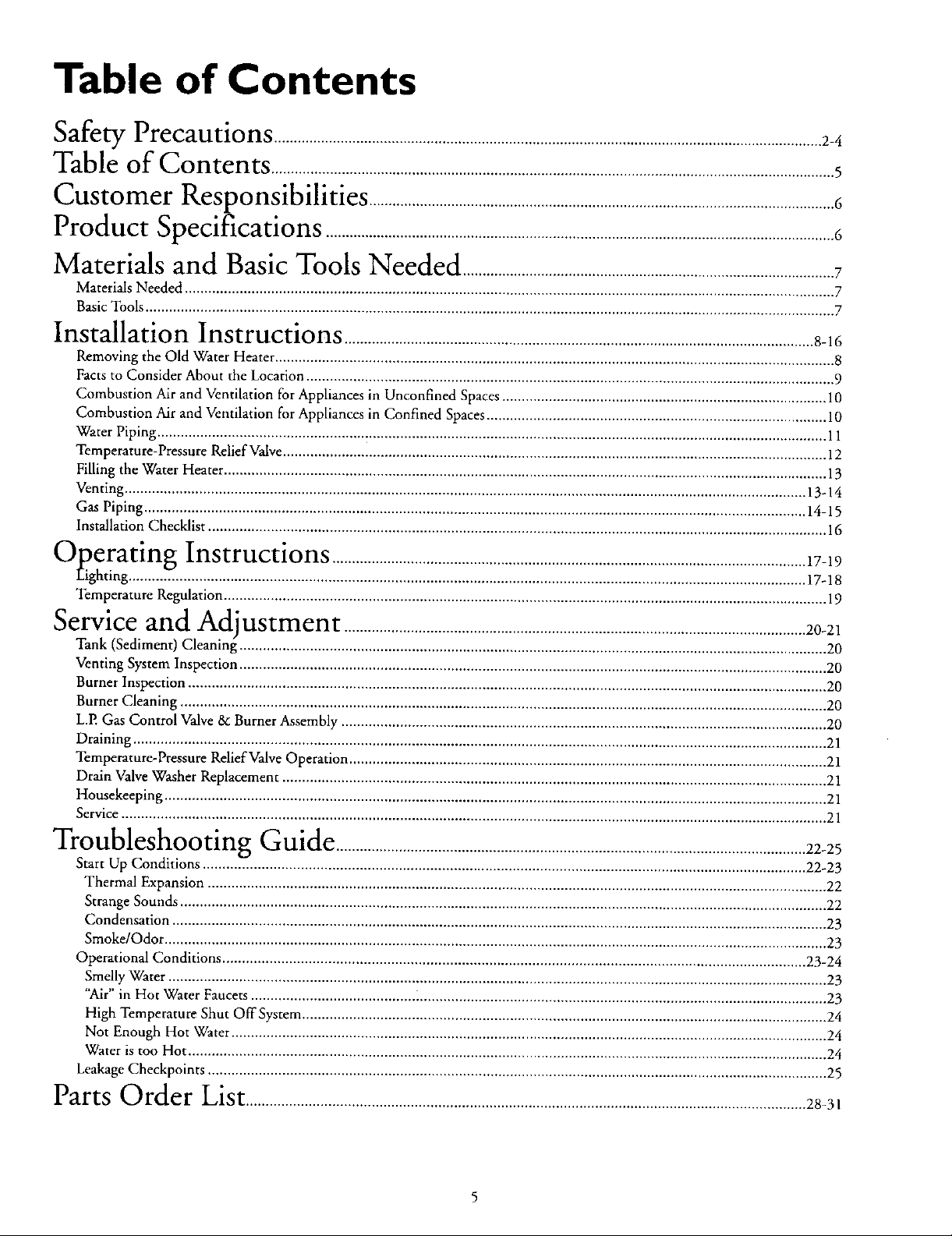
Table of Contents
<€,_,_,_,a,,._yPrecautions ............................................................................................................................................2-4
Table of Contents ................................................................................................................................................5
Customer
Product
lZesponslblhtles .......................................................................................................................6
bpecmcanons ..................................................................................................................................6
Materials and Basic Tools Needed ...............................................................................................7
Materials Needed ...................................................................................................................................................................... 7
BasicTools ................................................................................................................................................................................ 7
Installation Instructions ........................................................................................................................8-16
Removing the Old Water Heater ............................................................................................................................................... 8
Facts to Consider About the Location ....................................................................................................................................... 9
Combustion Air and Ventilation for Appliances in Unconfined Spaces ................................................................................... 10
Combustion Air and Ventilation for Appliances in Confined Spaces ....................................................................................... 10
Water Piping ........................................................................................................................................................................... 11
Temperature-Pressure Relief Valve........................................................................................................................................... 12
Filling the Water Heater .......................................................................................................................................................... 13
Venting .............................................................................................................................................................................. 13-14
Gas Piping ......................................................................................................................................................................... 14-15
Installation Checklist .............................................................................................................................................................. 16
"""Operating Instructions .........................................................................................................................17-19
Eight ng .7.. ...................................................................................................... 17-18
Temperature Regulation.......................................................................................................................................................... 19
Service and
Tank (Sediment) Cleaning--...................................................................................................................................................... 20
Venting System Inspection ...................................................................................................................................................... 20
Burner Inspection ................................................................................................................................................................... 20
Burner Cleaning ..................................................................................................................................................................... 20
L.P. Gas Control Valve & Burner Assembly ............................................................................................................................ 20
Draining ................................................................................................................................................................................. 21
Temperature-Pressure Relief Valve Operation .......................................................................................................................... 21
Drain Valve Washer Replacement ........................................................................................................................................... 21
Housekeeping ......................................................................................................................................................................... 21
Service .................................................................................................................................................................................... 21
Adlustment ......................................................................................................................20-21
_'_ "" -"lroubleshootmg Guide ........................................................................................................................22-25
Start Up Conditions .......................................................................................................................................................... 22-23
Thermal Expansion .............................................................................................................................................................. 22
Strange Sounds ..................................................................................................................................................................... 22
Condensation ....................................................................................................................................................................... 23
Smoke/Odor ......................................................................................................................................................................... 23
Operational Conditions ..................................................................................................................................................... 23-24
Smelly Water ........................................................................................................................................................................ 23
"Air" in Hot Water Faucets .......................................... i........................................................................................................ 23
High Temperature Shut OffSysrem ...................................................................................................................................... 24
Not Enough Hot Water ........................................................................................................................................................ 24
Water is too Hot ................................................................................................................................................................... 24
Leakage Checkpoints .............................................................................................................................................................. 25
Parts Order List...............................................................................................................................................28-3,
Customer Responsibilities
Thank You for purchasinga Sears water heater
Properly installed and maintained, it should give you years of
trouble free service. If you should decide that you want the new
water heater professionally installed by Sears call the local Sears
Service Center or any Sears store. They will arrange for prompt,
quality installation by Sears authorized contractors.
Abbreviations Found In This Instruction Manual
C.S.A. - Canadian Standards Association ,
A.N.S.I. - American National Standards Institute
N.EEA. - National Fire Protection Association
AWARNING
This gas-fired water heater is design certified by CSA
INTERNATIONAL under American National
StandardlCSA Standard for Gas Water Heaters ANS
Z21.10.1 • CSA 4.1 (latest edition). The installation must
conform with this manual, Local Codes and with the latest
edition of the National Fuel Gas Code, ANSI Z223.1.
This publication is available from your local government or
public library, gas company, or by writing NFPA,
Batterymarch Park, Quincy, MA 02269.
• Read the "Safety Precautions" section, pages 2 through 4 of
this manual first and then the entire manual carefully. If you
don't follow the safety rules, the water beater will not operate
properly. It could cause DEATH, SERIOUS BODILY
INJURY AND/OR PROPERTY DAMAGE.
This manual contains instructions for the installation, opera-
tion, and maintenance of the gas-fired water heater. It also
contains warnings through out the manual that you must read
and be aware of. All warnings and all instructions are essential
to the proper operation of the water beater and your safety.
Since we cannot put everything on the first few pages, READ
THE ENTIRE MANUAL BEFORE ATTEMPTING TO
INSTALL OR OPERATE THE WATER HEATER.
The installation must conform with the instructions in this
manual; gas company rules; and Local Codes, or in the
absence of Local Codes, with the latest edition of the National
Fuel Gas code, ANSI Z223.1, also referred to as NFPA 54
This publication is available from your local government or
public library or gas company or by writing NFPA,
Barterymarch Park, Quincy, MA 02269.
If after reading this manual you have any questions or do not
understand any portion of the instructions, call the Sears
Service Center.
Carefully plan the place where you are going to put the water
bearer. Correct combustion, vent action, and vent pipe instal-
lation are very important in preventing death from possible
carbon monoxide poisoning and fires.
Examine the location to ensure the water heater complies with
the "Facts to Consider About the Location" section in this
manual.
For California installation this water heater must be braced,
anchored, or strapped to avoid falling or moving during an
earthquake. See instructions for correct instaI[ation proce-
dures. Instructions may be obtained from your local dealer,
wholesaler, public utilities or California Office of the State
Architect, 400 P Street, Sacramento, CA 95814.
Complies with SCAQMD rule #1121 and districts having
equivalent NOx requirements.
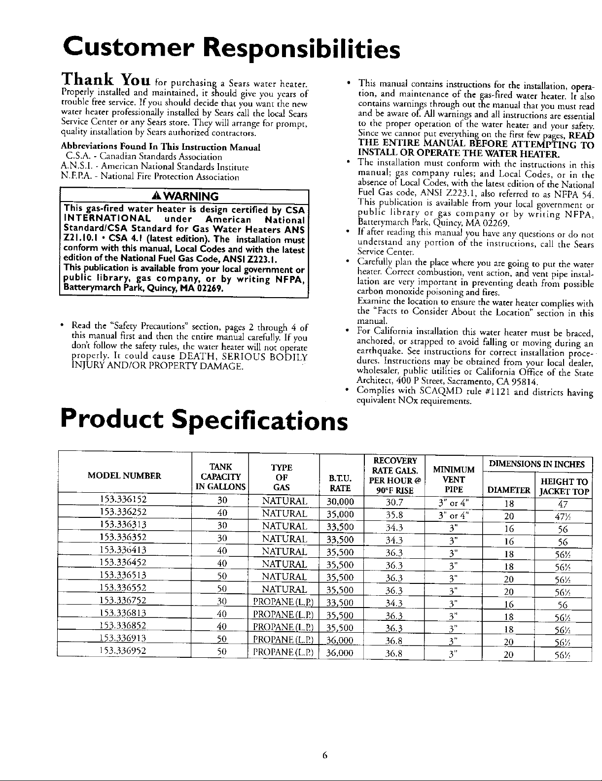
Product Specifications
MODEL NUMBER
153.336152
153.336252
153.336313
153.336352
153.336413
153.336452
153.336513
153.336552
153.336752
153.336813
153.336852
153.336913
153.336952
TANK
CAPACITY
IN GALLONS
30
40
30
30
40
40
50
50
30
40
40
50
50
TYPE
OF
GAS
NATURAL
NATURAL
NATURAL
NATURAL
NATURAL
NATURAL
NATURAL
NATURAL
PROPANE (L.E)
PROPANE (L.E)
PROPANE (L.E)
PROPANE (L.E)
PROPANE (L.P,)
B.ZU.
RATE
30,000
35,000
33,500
33,500
35,500
35,500
35,500
35,500
33,500
35,500
35,500
36_000
36,000
RECOVERY
RATEGALS.
PERHOUR @
90°F RISE
30.7
35.8
34.3
34.3
36.3
36.3
36.3
36.3
34.3
36.3
36.3
36.8
36.8
MINIMUM
VENT
PIPE
3" or4"
3" or 4"
3"
3"
3"
3"
3"
3"
3"
3"
3"
3"
3"
DIMENSIONS IN INcHEs
HEIGHT TO
DIAMETER JACKETTOP
18 47
20 47_
16 56
16 56
18 56_
18 56_
20 56½
20 56_
16 56
18 56_
18 56_
20 56_
20 56%
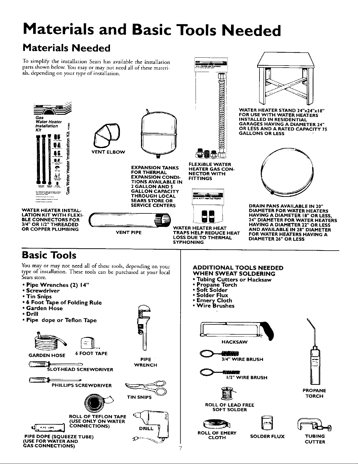
Materials and Basic Tools Needed
Materials Needed
To simplify the installation Sears has available the installation
parts shown below. You may or may not need all of these materi-
als, depending on your type of installation.
WATER HEATER STAND 24"x24"x I 8"
FOR USE WITH WATER HEATERS
Gas
Water Heater
Installation
Kit
INSTALLED IN RESIDENTIAL
GARAGES HAVING A DIAMETER 24"
OR LESS AND A RATED CAPACITY 75
GALLONS OR LESS
@
VENT ELBOW
EXPANSION TANKS
FOR THERMAL
EXPANSION CONDI-
TIONS AVAILABLE IN
2 GALLON AND 5
GALLON CAPACITY
THROUGH LOCAL
SEARS STORE OR
SERVICE CENTERS
WATER HEATER INSTAL-
LATION KIT WITH FLEXI-
BLE CONNECTORS FOR
314" OR 1/2" THREADED
OR COPPER PLUMBING
_ WATER HEATER HEAT
Basic Tools
You may or may not need all of these tools, depending on your
type of installation. These tools can be purchased at your local
Sears store.
• Pipe Wrenches (2) 14"
• Screwdriver
• Tin Snips
• 6 Foot Tape of Folding Rule
• Garden Hose
• Drill
• Pipe dope or Teflon Tape
FLEXIBLE WATER
HEATER GAS CON-
NECTOR WITH
FITTINGS
TRAPS HELP REDUCE HEAT
LOSS DUE TO THERMAL
SYPHONING
ADDITIONAL TOOLS NEEDED
WHEN SWEAT SOLDERING
• Tubing Cutters or Hacksaw
• Propane Torch
• Soft Solder
• Solder Flux
_ EmeryCIoth
Wire Brushes
DRAIN PANS AVAILABLE IN 20"
DIAMETER FOR WATER HEATERS
HAVING A DIAMETER 18" OR LESS,
24" DIAMETER FOR WATER HEATERS
HAVING A DIAMETER 22" OR LESS
AND AVAILABLE IN 28" DIAMETER
FOR WATER HEATERS HAVING A
DIAMETER 26" OR LESS
GARDEN HOSE 6 FOOT TAPE
SLOT-HEAD SCREWDRIVER
PHILLIPS SCREWDRIVER
ROLL OF TEFLON TAPE
(USE ONLY ON WATER
CONNECTIONS)
PIPE DOPE (SQUEEZE TUBE)
(USE FOR WATER AND
GAS CONNECTIONS)
PIPE
WRENCH
TIN SNIPS
DRILL
HACKSAW
3/4" WIRE BRUSH
1/2" WIRE BRUSH
PROPANE
TORCH
ROLL OF LEAD FREE
SOFT SOLDER
ROLL OF EMERY
CLOTH SOLDER FLUX TUBING
CUTTER
7
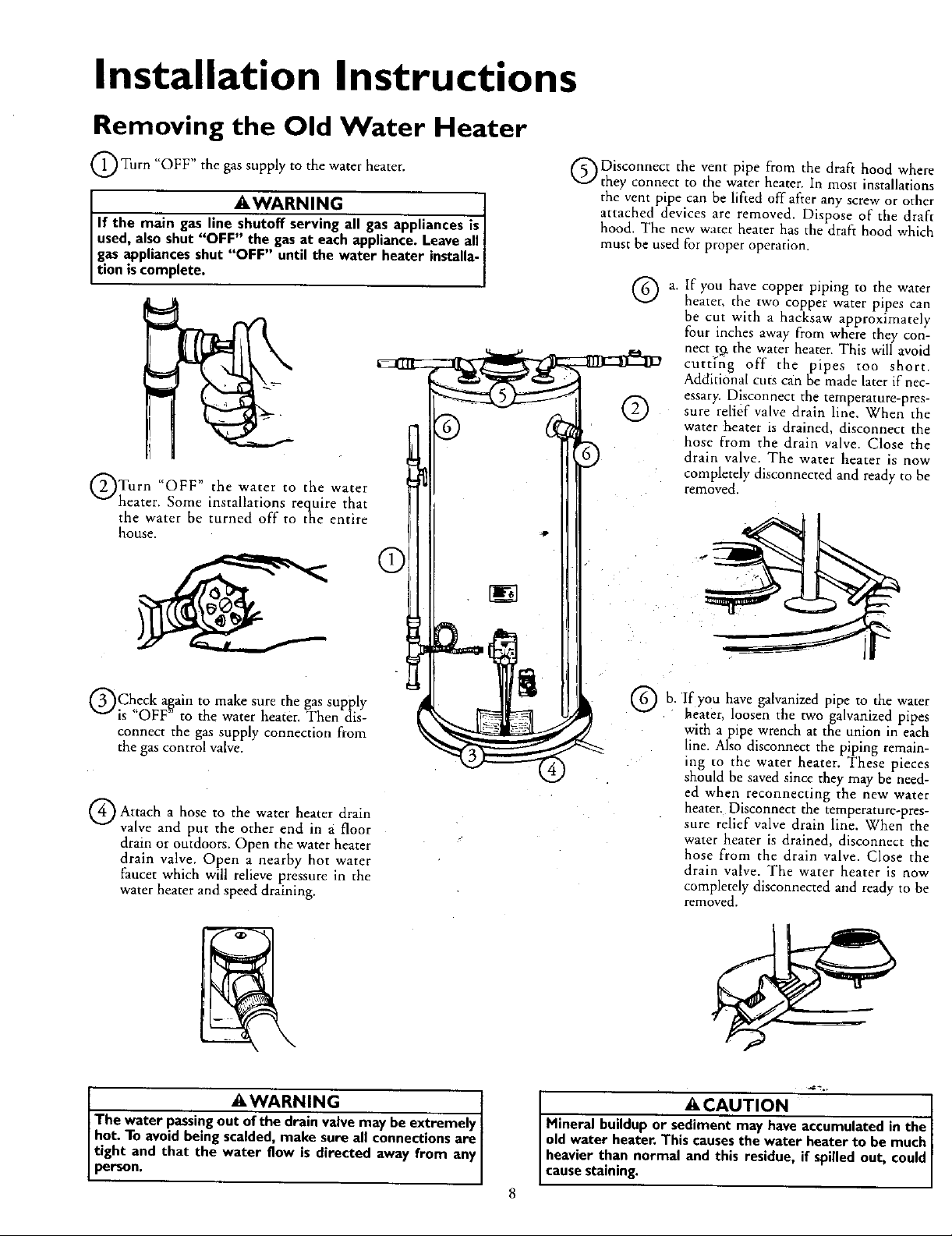
Installation Instructions
Removing the Old Water Heater
O Turn "OFF" the gas supply to the water heater.
AWARNING
If the main gas line shutoff serving all gas appliances is
used, also shut "OFF" the gas at each appliance. Leave all
gas appliances shut "OFF" until the water heater installa-
t on scomp ete.
QTurn "OFF" the water to the water
heater. Some installations require that
the water be turned off to the entire
house.
C
ODisconnect the vent pipe from the draft hood where
they connect to the water heater. In most installations
the vent pipe can be lifted off after any screw or other
attached devices are removed. Dispose of the draft
hood. The new water heater has the draft hood which
must be used for proper operation.
®
If you have copper piping to the water
heater, the two copper water pipes can
be cut with a hacksaw approximately
four inches away from where they con-
nect tg the water heater. This will avoid
curt[fig off the pipes too short.
Additional cuts c_in be made later if nec-
essary. Disconnect the temperature-pres-
sure relief valve drain line. When the
water heater is drained, disconnect the
hose from the drain valve. Close the
drain valve. The water heater is now
completely disconnected and ready to he
removed.
QCheck a,g,ain to make sure the gas supply
is OFF to the water heater. Then dis-
connect the gas supply connection from
the gas control valve.
Q Attach hose the heater drain
a to water
valve and put the other end in a floor
drain or outdoors. Open the water heater
drain valve. Open a nearby hot water
faucet which will relieve pressure in the
water heater and speed draining.
AWARNING t
The water passing out of the drain valve may be extremely I
hot. To avoid being scalded, make sure all connections are
tight and that the water flow is directed away from any
person.
you
b. If have galvanized pipe to the water
heater, loosen the two galvanized pipes
with a pipe wrench at the union in each
line. Also disconnect the piping remain-
ing to the water heater. These pieces
should be saved since they may be need-
ed when reconnecting the new water
heater. Disconnect the temperature-pres-
sure relief valve drain line. When the
water heater is drained, disconnect the
hose from the drain valve. Close the
drain valve. The water heater is now
completely disconnected and ready to be
re.loved,
ACAUTION I
Mineral buildup or sediment may have accumulated in the
old water heater. This causes the water heater to be much
heavier than normal and this residue, if spilled out, could
cause staining.
Installation Instructions (cont'd)
Facts to Consider About the
Location
You should carefully choose an indoor location for the new
water heater, because the placement is a very important consid-
eration for the safety of the occupants in the building and for
the most ecmiomical use of the appliance. This water heater is
not for use in mobile homes or outdoor installation.
Whether replacing an old water heater or putting the water
heater in a new location, the following critical points must be
observed.
• The location selected should be indoors as close as practical to
the gas vent or chimney to which the water heater vent is
going to be connected, and as centralized with the water pip-
ing system as possible. The water heater, as all water heaters,
will eventually leak. Do not install without adequate drainage
provisions where water flow will cause damage.
ACAUTION
WATER HEATERS EVENTUALLY LEAK:Installationofthe
water heatermust beaccomplishedin sucha manner that if
thetank or any connectionsshouldleak,theflowofwaterwill
not causedamageto the structure.Forthis reason,it isnot
advisableto installthe water heaterin an atticor upperfloor.
When suchlocationscannotbe avoided,a suitabledrain pan
shouldbe installedunderthe water heater. Drain pansare
availableat your localSearsstore.Sucha drain panmust be
not greaterthan 1¼inchesdeep,havea minimum lengthand
widthofat least2inchesgreaterthanthewater heaterdimen-
sionsandmust be pipedto an adequatedrain.The panmust
notrestrict combustionairflow.Underno circumstancesisthe
manufactureror Searsto be heldliablefor any waterdamage
inconnectionwiththis waterheater.
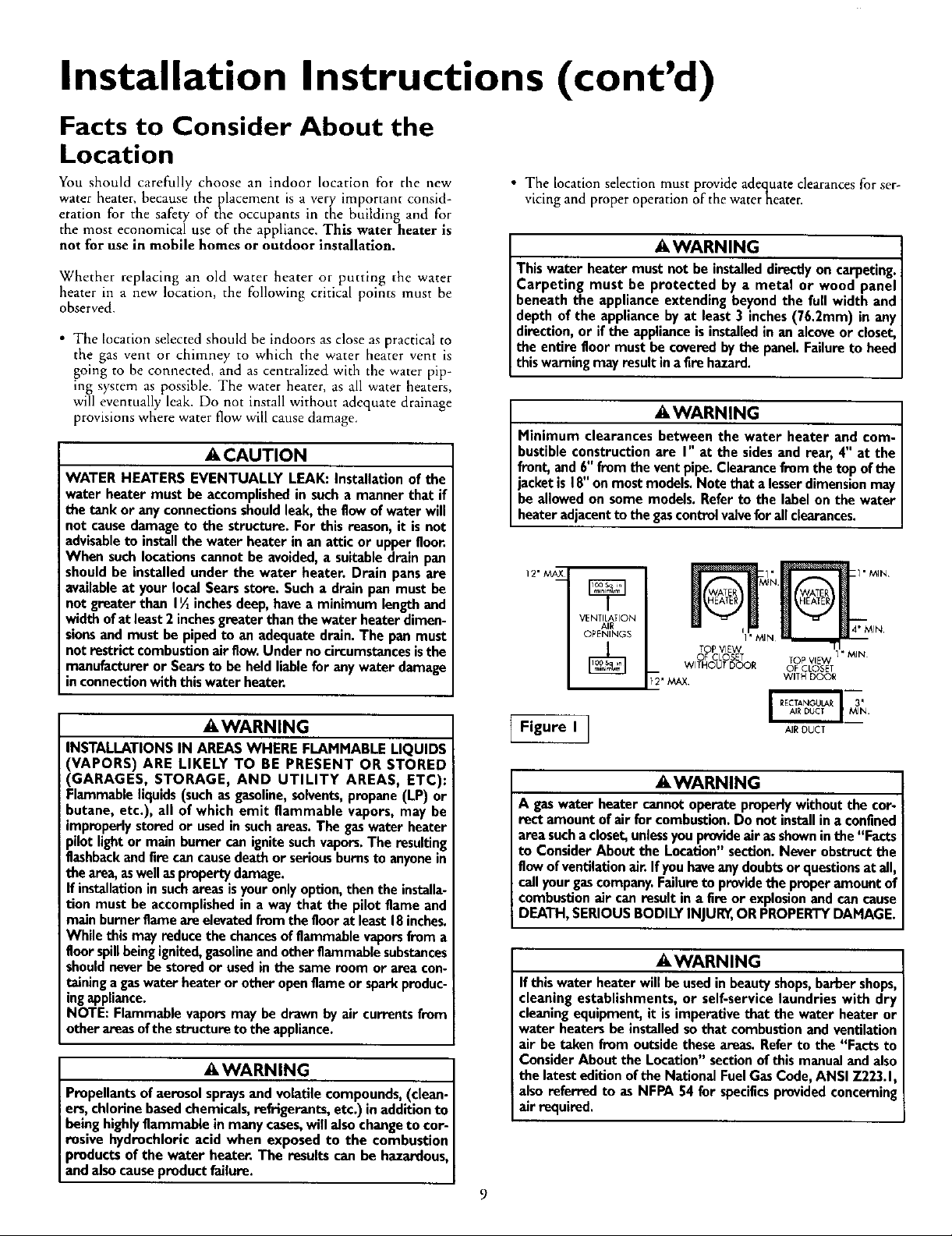
• The location selection must provide adec_uateclearances for ser-
vicing and proper operation of the waterneater.
AWARNING
Thiswater heater mustnot be installeddirectlyon carpeting.
Carpeting must be protected by a metal or wood panel
beneaththe applianceextendingbeyondthe full width and
depthof the appliance byat least3 inches(76.2mm) in any
direction,or ifthe applianceisinstalledin an alcoveor closet,
the entirefloor must be coveredbythe panel.Failureto heed
this warningmayresult inafirehazard.
AWARNING
Minimum clearancesbetween the water heater and com-
bustibleconstructionare I" at the sidesand rear, 4" at the
front,and 6"fromthe ventpipe.Clearancefromthe topofthe
jacketis 18"onmostmodels.Notethat alesserdimensionmay
beallowedon some models. Referto the labelonthe water
heateradjacentto the gascontrolvalveforallclearances.
12" _X
VENTILATION
AIR
OPENINGS
[_' MAX WITH DOOR
TOP VIEW _ I
OF CLOSET TOP VIEW
WITHOUT DOOR OF CLOSET
I'MIN
A WARNING
INSTALLATIONS IN AREAS WHERE FLAMMABLE LIQUIDS
(VAPORS) ARE LIKELY TO BE PRESENT OR STORED
(GARAGES, STORAGE, AND UTILITY AREAS, ETC):
Flammable liquids (such as gasoline, solvents,propane (LP) or
butane, etc.), all of which emit flammable vapors, may be
improperly stored or used in such areas. The gaswater heater
pilot light or main burner can ignite such vapors.The resulting
flashbackand fire can cause death or serious burnsto anyone in
the area, as well asproperty damage.
If installation in suchareas is your only option, then the installa-
tion must be accomplished in a way that the pilot flame and
main burner flame are elevated from the floor at least 18 inches.
While this may reduce the chancesof flammable vaporsfrom a
floor spillbeing ignited,gasolineand other flammable substances
should never be stored or used in the same room or area con-
taining a gaswater heater or other open flame or spark produc-
ingappliance.
NOTE: Flammable vapors may be drawn by air currents from
other areas of the structure to the appliance.
AWARNING
Propellants of aerosol spraysand volatile compounds, (clean-
ers, chlorine based chemicals, refrigerants, etc.) in addition to
being highly flammable in many cases,will also change to cor-
rosive hydrochloric acid when exposed to the combustion
products of the water heater. The results can be hazardous,
and also cause product failure.
Figure I_
AIR OUCT
A WARNING
A gaswater heater cannotoperateproperlywithoutthe cor-
rect amount ofair for combustion.Do not installina confined
areasuchacloset,unlessyouprovideair asshowninthe "Facts
to ConsiderAbout the Location"section.Neverobstructthe
flowofventilationair Ifyouhaveanydoubtsorquestionsatall,
callyour gascompany.Failuretoprovidethe properamount of
combustionair can result in a fire or explosionand cancause
DEATH,SERIOUSBODILYINJUR_,OR PROPERTYDAMAGE.
AWARNING
If this water heater will be usedin beauty shops,barber shops,
cleaning establishments, or self-service laundries with dry
cleaningequipment, it is imperative that the water heater or
water heaters be installed so that combustion and ventilation
air be taken from outside these areas. Refer to the "Facts to
Consider About the Location" section of this manual and also
the latest edition of the National FuelGas Code, ANSI Z223.1,
also referred to as NFPA 54 for specificsprovided concerning
air required.
9
Installation Instructions (cont'd)
Combustion Air and Ventilation
for Appliances Located in
Unconfined Spaces
Unconfined Space is a space whose volume is not less than 50
cubic feet per 1,000 Btu per hour of the aggregate input rating
of all appliances installed in that space. Rooms communicating
directly with the space in which the appliances are installed,
through openings not furnished with doors, are considered a
part of the unconfined space
In unconfined spaces in buildings, infiltration may be adequate
to provide air for combustion, ventilation and dilution of flue
gases. However, in buildings of tight construction (for example,
weather stripping, heavily insulated, caulked, vapor barrier, etc.),
additional air may need to be provided using the methods
described in Combustion Air and Ventilatiorl for Appliances
Located in Confined Spaces, b.
Combustion Air and Ventilation
for Appliances Located in
Confined Spaces
Confined Space is a space whose volume is less than 50 cubic
feet per 1,000 Btu per hour of the aggregateinput rating of all
appliances installed in that space.
a. ALL AIR FROM INSIDE BUILDINGSt
(See Page 8 Figure l, and Figure 2 below)
The confined space shall be provided with two permanent
openings communicating directly with an additional room(s)
of sufficient volume so that the combined volume of all
spaces meets the criteria for an unconfined space. The total
input of all gas utilization equipment installed in the com-
bined space shall be considered in making this determination.
Each opening shall have a minimum free area of one square
inch per 1,000 BTU per hour of the total input rating of all
gas utilization equipment in the confined space, but not less
than 100 square inches. One opening shall commence within
12 inches of the top and one commencing within 12 inches
of the bottom of the enclosure.
S VENT
--3
Figure 2 ]
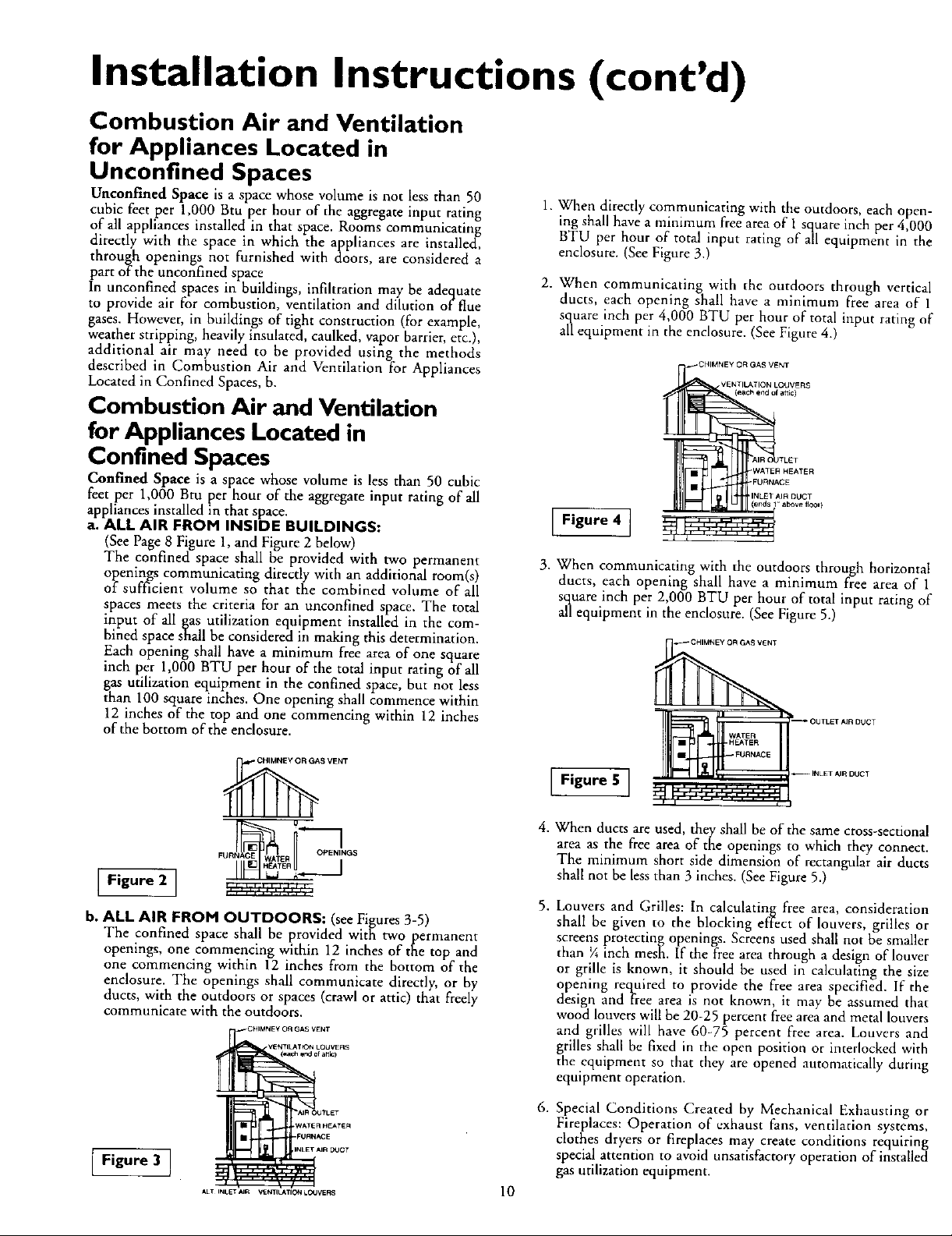
b. ALL AIR FROM OUTDOORS: (see Figures 3-5)
The confined space shall be provided with two permanent
openings, one commencing within 12 inches of the top and
one commencing within 12 inches from the bottom of the
enclosure. The openings shall communicate directly, or by
ducts, with the outdoors or spaces (crawl or attic) that freely
communicate with the outdoors.
II I_.J ,¢_.m.i_-,
CHIMNEy O_ GAS VENT
VE_TIt_T_ LOUVERS
(_ar_ end e{ attic)
1. When directly communicating with the outdoors, each open-
ing shall have a minimum free area of 1 square inch per 4,000
BTU per hour of total input rating of all equipment in the
enclosure. (See Figure 3.)
2. When communicating with the outdoors through vertical
ducts, each opening shall have a minimum free area of 1
square inch per 4,000 BTU per hour of total input rating of
all equipment in the enclosure. (See Figure 4.)
_CHIMNEY OR GAS VENT
Figure 4 ]
3. When communicating with the outdoors through horizontal
ducts, each opening shall have a minimum free area of 1
square inch per 2,000 BTU per hour of total input rating of
all equipment in the enclosure. (See Figure 5.)
_ CHIMNEY OR GAS VENT
Figure 5 ]
,
When ducts are used, they shall be of the same cross-sectional
area as the free area of the openings to which they connect.
The minimum short side dimension of rectangular air ducts
shall not be less than 3 inches. (See Figure 5.)
,
Louvers and Grilles: In calculating free area, consideration
shall be given to the blocking effect of louvers, grilles or
screens protecting openings. Screens used shall not be smaller
than ¼ inch mesh. If the free area through a design of louver
or grille is known, it should be used in calculating the size
opening required to provide the free area specified. If the
design and free area is not known, it may he assumed that
wood louvers will be 20-25 percent free area and metal louvers
and grilles will have 60-75 percent free area. Louvers and
grilles shall be fixed in the open position or interlocked with
the equipment so that they are opened automatically during
equipment operation.
VENTILATION LOUVERS
(each end of attic)
WATER HEATER
FURNACE
LET
INLET AIR DUCT
above tloor }
i_ OUTLET AJR DUCT
WATER
HEATER
FURNACE
-- INLET AIR DUCT
Figure 3 ]
AIR OUTLET
WATER HEATER
_IR DOCT
ALT INLETAIR VENTILATIONLO4JVERS
FURN,'_3E
6. Special Conditions Created by Mechanical Exhausting or
Fireplaces: Operation of exhaust fans, ventilation systems,
clothes dryers or fireplaces may create conditions requirin_
special attention to avoid unsatisfactory operation of insta[leci
gas utilization equipment.
10

Installation Instructions (cont'd)
Water Piping
A WARNING
HOTTERWATERCAN SCALD:Water heatersare intendedto
producehotwater.Water heatedto a temperaturewhichwill
satisfyclotheswashing,dishwashing,andothersanitizingneeds
canscaldandpermanentlyinjureyouupon contact.Somepeo-
plearemore likelyto bepermanentlyinjuredbyhot waterthan
other_Theseincludethe elderly,children,theinfirm or physical-
ly/mentallyhandicapped.Ifanyoneusinghotwater inyourhome
fitsintooneofthesegroupsor ifthereisa localcodeor statelaw
requiringa certaintemperaturewaterat the hotwater_ then
youmust take specialprecautions.Inadditiontousingthe lowest
possibletemperaturesettingthatsatisfiesyourhotwaterneeds,
a meanssuchasa mixingvalve,shouldbe usedat thehotwater
tapsusedby thesepeopleor at the waterheater,Mixingvalves
areavailableat plumbingsupplyor hardwarestores.Followman-
ufacturersinstructionsfor installationof the valves.Before
changingthe factory setting on the thermostat, read the
"Temperature Regulation"sectioninthismanual.
This water heater shall not be connected to any heating systems
or component(s) used with a non-potable water heating
appliance.
If a water heater is installed in a closed water supply system;
such as one having a back-flow preventer, check valve, water
meter with a check valve, etc.., in the cold water supply; means
shall be provided to control thermal expansion. Contact the
local utility or local Sears Service Center on how to control this
situation.
NOTE: To _protect against untimely corrosion of hot and
cold water ttttings, it is strongly recommended that di-elec-
tric unions or couplings be installed on this water heater
when connected to copper pipe.
• Look at the top cover of the water heater. The cold water
inlet is marked cold. Put two or three turns of teflon tape
around the threaded end of the threaded-to-sweat coupling
and around both ends of the _" threaded nipple. Using flexi-
ble connectors, connect the cold water pipe to the coldwater
inlet of the water heater.
NOTE: This water heater is super insulated to minimize
heat loss from the tank. Further reduction in heat loss
can be accomplished by insulating the hot water lines
from the water heater.
INSTALLATION COMPLETED USING
SEARS INSTALLATION KIT
FLEXIBLE VALVE
WATER
CONNECTORS
HOT OUTLET
TO HOUSE
THREADED TO _ SWEAT
SWEAT COUPLING _ COUPLING
THREADED TO
,,4,THREADED 3,,'--THREADED
COUPLING _
SHUTOFF
WATER LINE
COLD INLET
COUPLING
The illustration shows the attachment of the water piping to the
water heater. The water heater is equipped with ¾" water con-
nections.
NOTE: If using copper tubing, solder tubing to an adapter
before attaching the adaptor to the cold water inlet connec-
tion. Do not solder the cold water supply line direcdy to the
cold water inlet. It will harm the dip tube and damage the
tank.
Look at the top cover of the water heater. The water outlet is
marked hot. Put two or three turns of teflon tape around the
threaded end of the threaded-to-sweat coupling and around
both ends of the _" threaded nipple. Using flexible connec-
tors, connect the hot water pipe to the hot water outlet on
the water heater.
11
[]
I m
FLOOR DRAIN
--TEMPERATURE-
PRESSURE
RELIEF VALVE
-- DISCHARGE
PIPE (Do not cap
or plug)
I
6" AIR GAP

Installation Instructions (cont'd)
Temperature-Pressure Relief Valve
_,WARNING
At the time of manufacture this water heater was provided
with a combination temperature-pressures relief valve certi-
fied by a nationally recognized testing laboratory that main-
tains periodic inspection of production of listed equipment or
materials, as meeting the requirements for Relief Valves and
Automatic Gas Shutoff Devices for Hot Water Supply
Systems, and the latest edition of ANSI Z21.22 and the code
requirements of ASME. If replaced, the valve must meet the
requirements of local codes, but not less than a combination
temperature and pressure relief valve certified as meeting
the requirements for Relief Valves and Automatic Gas
Shutoff Devices for Hot Water Supply Systems, ANSI Z21.22
by a nationally recognized testing laboratory that maintains
periodic inspection of production of listed equipment or
materials.
The valve must be marked with a maximum set pressure not
to exceed the marked hydrostatic working pressure of the
water heater (150 Ibs./sq. in.) and a discharge capacity not
lessthan the water heater input rate as shown on the model
rating plate. (Electric heaters - watts divided by 1000 x 3415
equal BTU/Hr. rate.)
Your local jurisdictional authority, while mandating the use of
a temperature-pressure relief valve complying with ANSI
Z21.22 and ASME, may require a valve model different from
the one furnished with the water heater.
Compliance with such local requirements must be satisfied
by the installer or end user of the water heater with a locally
brescribed temperature-pressure relief valve installed in the
designated opening in the water heater in place of the facto-
ry furnished valve.
For safe operation of the water heater, the relief valve must
not be removed from it's designated opening or plugged.
The temperature-pressure relief valve must be installed
directly into the fitting of the water heater designated for the
relief valve. Position the valve downward and provide tubing
so that any discharge will exit only within 6 inches above, or
at any distance below the structural floor. Be certain that no
contact is made with any live electrical part. The discharge
opening must not be blocked or reduced in size under any
circumstances. Excessive length, over 30 feet, or use of more
than four elbows can cause restriction and reduce the dis-
charge capacity of the valve.
No valve or other obstruction is to be placed between the
relief valve and the tank. Do not connect tubing directly to
discharge drain unless a 6" air gap is provided. To prevent
bodily injury, hazard to life, or property damage, the relief
valve must be allowed to discharge water in quantities should
circumstances demand. If the discharge pipe is not connect-
ed to a drain or other suitable means, the water flow may
cause property damage.
The Discharge Pipe:
Must not be smaller in size than the outlet pipe size of the
valve, or have any reducing couplingsor other restrictions.
Must not be plugged or blocked.
Must be of material listed for hot water distribution.
Must be installed so as to allow complete drainage of both
the temperature-pressure relief valve, and the discharge
pipe.
Must terminate at an adequate drain.
Must not have any valve between the relief valve and tank.
AWARNING
The temperaturo-pressure relief valve must be manually
operated at least once a year. Caution should be taken to
ensure that (|) no one is in front of or around the outlet of
the temperature-pressure relief valve discharge line, and (2)
the water manually discharged will not cause any bodily
injury or property damage because the water may be
extremely hot.
If after manually operating the valve, it fails to completely
reset and continues to release water, immediately close the
cold water inlet to the water heater, follow the draining
instructions, and replace the temperature-pressure relief i
valvewith anew one.
HOT
SHUTOFF
VALVE
-DISCHARGE PIPE
COLD
PRESSURE
RELIEF VALVE
(Do not cap or plug)
[]
6" AIR GAP
FLOOR DRAIN
RELIEFVALVEOPENING
At the time of manufacture, this water heater was provided with a combination tem-
perature-pressure Telief_aNe gsted as cornpl_ngwith the s_andardfor relief vanes and
automatic gas shut-off devices for hot water supply systems, ANSI Z21.22. For safe
operation of the water heate_ the relief valvemust not be removed from its designated
point of installation or plugged.
Your local jurisdictional authority, while mandating the use of a temperature-pressure
relief valvecomplying with ANSI Z21,22 and ASME, may require a valvemodel different
from the one furnished with the water heater
Compliance with such local requirements must be satisfied by the installer of end user
of the water heater with a locallyprescribed temperature-pressure relief valveinstalled
in the designated opening int_ water he_er.
See manual heading ."Temperature.Pressure Relief Valves" for installation and mainte-
nance of relief valve, discharge line,and other safety precautions.
12

Installation Instructions (cont'd)
Filling the Water Heater
A CAUTION
Never use this water heater unless it is completely filled with J
water. To prevent damage to the tank, the tank must be filled J
with water. Water must flow from the hot water faucet
before turn ng ON gasto the water heater.
To fill the water heater with water:
• Close the water heater drain valve by turning the handle to
the right (clockwise). The drain valve is on the lower front of
the water heater.
• Open the cold water supply valve to the water heater.
NOTE: The cold water supply valve must be left open
when the water heater is in use.
• To insure complete filling of the tank, allow air to exit by
opening the nearest hot water faucet. Allow water to run
until a constant flow is obtained. This will let air out of the
water heater and the piping.
• Check all new water piping for leaks. Repair as needed.
Venting
A WARNING
VENT DAMPERS - Any vent damper, whether it is operated
thermally or otherwise must be removed if its useinhibits prop-
er drafting of the water heater.
Thermally Operated Vent Dampers: Gas-fired water heaters
havingthermal efficiency in excessof 80% may produce a rela-
tively low flue gastemperature. Suchtemperatures may not be
high enough to properly open thermally operated vent
dampers. This would cause spillageof flue gasesand may cause
carbon monoxide poisoning.
Vent dampers must bear evidence of certification as complying
with the latest edition of American National Standard ANSI
Z21.68 (ANSI Z21.66 & 67, respectively, cover electrically and
mechanically actuated vent dampers). Before installation of any
vent damper, consultyour local SearsService Center or the gas
utility for further information.
For proper venting in certain installations, a larger diameter vent
pipe may be necessary. Due to great variances in installations,
unforeseeable by the manufacturer of the water heater, you mus
consult )'our gas company to aid you in determining the proper
venting for your water heater from the vent tables in the latest edi-
tion of the National Furl Gas Code ANSI Z223.l, aim referred to
as NFPA 54.
Check the venting system for signs of obstruction or deterioration
and replace if needed.
The combustion and ventilation air flow must not be obstructed.
f A WARNING
Obstructedor deterlo_s maypresenta serious
healthriskor asphyxiation.
• Place the draft hood legs in the receiving holes on the top of
the water heater. The legs will snap in the holes to give a
tight fit.
• Place the vent pipe over the draft hood. With the vent pipe in
position, drill a small hole through both the vent pipe and
draft hood. Secure them together with a sheet metal screw.
DR,FTHOOD I
VENT
ISC REW___J DRAFT HOOD
' -- '" OR
DRAFT H_
AWARNING I
The water heater with draft hood installed must be properly
vented to a chimney which terminates outdoors. Never oper- I
ate the water heater unlessit isvented to the outdoors and hasI
adequate air supply to avoid risks of improper operation, explo-
sionor asphyx at on.
AWARNING
To insure proper venting of this gas-fired water heater, the
correct vent pipe diameter must be utilized. Any additions or
deletions of other gas appliances on a common vent with this
water heater may.adversely affect the operation of the water
heater. Consult the local Sears Service Center or gasutility if
any such changesare planned.
AWARNING J
The vent pipe from the water heater must be no less than the J
diameter of the draft hood outlet on the water heater, and
must slope upward to the chimney at least ¼ inch per linear
foot.
13

Installation Instructions (cont'd)
Venting (cont'd) Gas Piping
All vent gases must be completely vented to the outdoors of the
structure (dwelling). Installonly the draft hood provided with
the new water heater and no other draft hood.
Vent pipes must be secured at each joint with sheet metal screws.
CHITHONEY
R I I
!
VENT PIPE INSTALLATION
There must be a minimum of 6" clearance between single wall
vent pipe and any combustible material. Fill and seal any clear-
ance between single wall vent pipe and combustible material
with mortar mix, cement, or other noncombustible substance.
For other than single wall, follow vent pipe manufacturer's clear-
ance specifications. To insure a tight fit of the vent pipe in a
brick chimney, seal around the vent pipe with mortar mix
cement.
AWARNING
Failureto haverequired clearancesbetweenvent pipingand
combustiblematerialwill result ina Erehazard.
AWARNING
Make sure the gas suppliedisthe same type listedon the
model rating plate. The inlet gaspressuremust not exceed
10.5in. water column(2.6kPa)for naturalgasor 13in. water
column(3.2kPa) for propane(I-R) gas.The minimum inlet
gaspressurelistedon the model rating plate isfor the pur-
poseofinputadjustment.
AWARNING , I
If the gascontrolvalveissubjectedto pressuresexceeding½
poundper squareinch(3.SkPa),the damageto the gascon-
tre valvecoudresu t n a Ereor exp oslonfrom eaknggas.
AWARNING
If the main gaslineshutoffserving all gasappliancesis used,
alsoturn "OFF" the gasat eachappliance.Leaveallgasappli-
ancesshutoffunt the water heater nstai at on scompete.
A gas line of sufficient size must be run to the water heater.
Consult the latest edition of National Fuel Gas Code ANSI
Z223.1, also referred to as NFPA 54 and the gas company con-
cerning pipe size.
AWARNING
Besurevent pipeisproperlyconnectedto preventescapeof
dangerousfluegaseswhichcouldcausedeadlyasphyxiation.
_,WARNING
Chemical vapor corrosionof the flue and vent systemmay
occurif air for combustioncontainscertainchemicalvapors.
Spraycan propellants,cleaningsolvents,refrigerator and air
conditioner refrigerants,swimmingpool chemicals,calcium
andsodiumchloride,waxes,bleach,and processchemicalsare
typicalcompoundswhicharepotentiallycorrosive.
There must be:
• A readily accessible manual shut offvalve in the gas supply line
serving the water heater, and
• A drip leg (sediment trap) ahead of the gas control valve to help
prevent dirt and foreign materials from entering the gas control
ValVe.
• A flexible gas connector or a ground joint union between the
shutoff valve and control valve to permit servicing of the unit.
Be sure to check all the gas piping for leaks before lighting the
water heater. Use a soapy water solutiott, nor a match or opert
flame. Rinse offsoapy solution and wipe dry.
Standard ModeLs are for installatiott up to 3,300 feet above sea
level.
High Altitude Models are for installation from 3,300 to 5,500
feet above sea level.
lfa standard model is installed above 3,300 feet or a high altitude
model is installed above 5,500 feet, the input rating must be
reduced at the rate of 4 percent for each 1,000 feet above sea level.
Contact your local Sears Service Center or gas utility for further
information.
14

Installation Instructions (cont'd)
GAS PIPING WITH
FLEXIBLE CONNECTOR
he appliance and its gas connection must be leak tested
_bT _, WARNING
efore placing the appliance in operation.
_,WARNING
• The appliance and its individual shutoff valve must be discon-
nected from the gas supply piping system during any pressure
testing of the gas system at test pressures in excess of _/2
poundper square inch (3.5kPa).
• The appliance must be isolated from the gassupplypiping sys-
tem byclosing its individual manual shutoff valve during any
pressure testing of the gassupply piping system at test pres-
suresequal or lessthan ½ pound per square inch(3.5kPa).
Use pipe joint compound or teflon tape marked
_WARNING as being
resistant to the actionofpetroleum[Propane(LP,)] gases.
SEDIMENT TRAP
A sediment trap shall be installed as close to the inlet of the
water heater as practical at the time of water heater installation.
The sediment trap shall be either a tee fitting with a capped nip-
ple in the bottom outlet or other device recoFnized as an effec-
tive sediment trap. If a tee fitting is used, it shall be installed in
conformance with one of the methods of installation shown
below.
GROUNDIO'NT
GAS PIPING WITH ALL BLACK IRON
GROUND JOINT -_
GAS SUPPLY
PIPING FLEXIBLE GAS CONNECTOR
" " " _ (Sediment trap) GAS
CAP
PIPE TO GAS CONTROL
GAS SUPPLY
PIPING
Connecting the gas piping to the gas control valve of the water
heater can be accomplished by either of the two methods shown.
_,WARNING
Contaminants in the gaslines may cause improper operation
of the gas control valve that may result in fire or explosion.
Before attaching the gas line be sure that all gas pipe is clean
on the inside. To trap any dirt or foreign material in the gas
supply line, a drip leg (sometimes called a sediment trap)
must be incorporated in the piping. The drip leg must be
readily accessible. Install in accordance with the "Gas Piping"
section. Refer to the latest edition of the National Fuel Gas
Code, ANSI Z223.1, also referred to asNFPA 54.
UNION(Optional}T_ _
3" rain. DRIPLEG GAS
GO , OL
CAP
15

Installation Instructions (cont'd)
Installation Checklist
BEFORE LIGHTING THE PILOT:
• Check the gas lines for leaks.
a. Use a soapy water solution. DO NOT test for gas leaks
using a match or open flame.
b. Brush the soapy water solution on all gas pipes, joints and
fittings.
c. Cheo< for bubbling soap. This means you have a leak.
Turn "OFF" gas and make the necessary repairs.
d. Recheck for leaks.
e. Rinse offsoapy solution and wipe dry.
• Is the new temperature÷pressure relief valve properly installed
and piped to an adequate drain? See "Temperature-Pressure
Relief Valve" section.
• Are the cold and hot water lines connected to the water
heater correctly? See "Water Piping" instructions in the
"Installation Instructions" section.
• Is the water heater completely filled with water? See "Filling"
"nstructions in the Installation Instructions" section.
• Will a water leak damage anything? See the "Facts to
Consider About the Location" secnon.
• Is there proper clearance between the water heater and any-
thing that might catch fire? See the Facts to Consider About
the Location" section.
• Do you have adequate ventilation so that the water heater
will op,erate properly? See Combustion Air and Vennlanon"
in the Installation Instructions section.
• Is the draft hood vent piping properly secured? See "Venting"
nstruct'ons in the Installation Instruct ons' sect on.
SHUTOFF VALVE ---_
DRIP LEG_
(Sediment trap)
DRAIN VALVE /
HOT
GAS SUPPLY
TEE 2 _ --
I i
CAPri I
VENT PIPE TO
OUTDOORS
OR CHIMNEY SHUTOFF VALVE
t
COLD
UNION
DRAFTHOOD
/TEMPERATURE-
PRESSURE
RELIEF VALVE
-- DISCHARGE PIPE
(Do not cap or plug)
6" AIR GAP
• Is there proper clearance between the vent pipe and anything
that m'ght catch on fire? See "Venting instructions in the
Installat on Instrucuons section.
• ls the vent pipe properly sloped and does the vent terminate
outdoors? See "Venting" "nstruct'ons in the 'Installation
Instructions" section.
• Do you need to call your gas company to check the gas pipe
and its hookup?" section.
FLOOR DRAIN
_ _I_O_TAT_ GAS PRESSURE IN WC
I I I
MODEL RATING PLATE
16

Operating Instructions
Lighting
_WARNING
BEFORE LIGHTING [PROPANE (L.P.) GAS WATER
HEATERS]:Propane (LR) gasisheavierthanair.Shouldthere
be a leak in the system,the gaswill settle near the ground.
Basements,crawlspaces,skirted areasunder mobile homes
(evenwhenventilated),closetsandareasbelowgroundlevelwill
serve as pockets for the accumulation of this gas. Before
attemptingto lightor relight the waterheater'spilotor turning
ona nearbyelectricallightswitch,beabsolutelysurethere isno
accumulatedgasinthe area.Searchforodorofgasbysniffingat
groundlevelinthe vicinityofthe appliance.If odorisdetected,
followstepsindicatedat "For YourSafety"onthe coverpageof
this manualthenleavethepremises.
Lighting and operating instructions are located on front of the
water heater, above or to one side of the gas control valve.
AWARNING
AN ODORANT IS ADDED TO THE GASUSED
FOR YOUR SAFETY
IF YOU SMELLGAS:
Do not try to lightanyappliance.
Do not touchanyelectricalswitch;do not useanyphonein
yourbuilding.
Immediatelycallyourgassupplierfrom a neighbor'sphone.
Followthe gassuppliersinstructions.
If you cannotreach your gassupplier,call the fire depart-
ment.
BYTHIS WATER HEATER.
I Figure 6 I
I Figure 7 ]
AWARNING
DO NOT force the gas controlknob.Use onlyyour hand to
pushit downto lightthe pilot,or to turn it to "ON", "OFF"
or "PILOT". Never use a tool suchasa lever,wrenchor pli-
ers. Do not hit or damagethe knob.A damagedknob may
result in an explosionand serious injury.Ifyou haveproblem
turningthe knob, callthe gassupplierimmediately.
CHECK FOR LEAKS
Be sure to check all your gas pipes for leaks before lighting your
water heater. Use a soapy water solution, not a match or open
flame. Check the factory gas fittings after pilot is lit and gas con-
trol knob is still in "PILOT" position. Then, check the fittings
when the main burner is turned "ON". Use a soapy water solu-
tion for this, too.
Figure 8 I
INNER
DOOR
OR
OUTER DOOR
[Figore9]
17

Operating Instructions (cont'd)
Lighting label on the water heater as it appears above the thermostat
FOR YOUR SAFETY READ BEFORE LIGHTING
WARNING
if you do not follow these instructions exactly, a fire or explosion
may result causing property damage, personal injury or loss of life.
A. This appliancehas a pilot which mustbe lightedby
hand.Whenlightingthepilot,follow theseinstructions
exactly.
B.BEFORELIGHTINGsmellallaroundtheappliancearea
for gas. Be sure to smell next to thefloor because
somegasisheavierthanairandwillsettleonthefloor.
WHATTODO IFYOUSMELLGAS
• Donottry to light anyspp{iance.
• Do not touchany electric switch; do not use any
phoneinyourbuilding.
• Immediatelycall yourgassupplierfroma neighbor's
phone.Followthegassupplier'sinstructions.
LIGHTING INSTRUCTIONS
1.STOP!Readthesafetyinformationaboveonthislabel.
2.Removeouterdoor.
3. Set the thermostat to lowest settinq byturningthe
watertemperaturedial clockwise,(/ _,)to itslowest
temperaturesetting(witharrowondial)asshown.DO
NOT FORCE, _
unless knob is depressed slightly. DO NOT FORCE.
(Figure6,page17)
5. Waitfive (5) minutesto clearout anygas.If youthen
smellgas,STOP!Follow"B" in the safetyinformation
above on this label.If you don't smellgas, go to the
nextstep.
6. Remove(or open) innerdoor locatedbelowthe gas
controlunit.
7.Findpilot-followmetal THERMOCOUPLE_, PILOtBURNER
! tubefrom gascontrol.
Thepilotislocatedin
frontoftheburner.
8.If youdont smellgas,turnknobongasControlcounter
to "PILOT"position.(Figure7,page17)clockwise_
• If you cannotreachyourgas supplier,callthe fire
department.
C. Useonlyyou_hand to pushin orturnthe gascontrol
knob.Neverusetools.If the knobwillnot pushin or
turnbyhand,don'ttryto repairit,call a qualifiedser-
vicetechnician.Forceor attemptedrepairmayresult
inafire or explosion.
D. Do not usethisapplianceif any parthas beenunder
water.Immediatelycall a qualifiedservicetechnician
to inspecttheapplianceand toreplaceanypartof the
controlsystemand any gascontrolwhichhas been
underwater.
9. Push in control knob all the way and hold down.
immediatelylightthe pilotwitha match. Continueto
hold controlknob in for aboutone (1) minuteafter
thepilot is lit. Releaseknobandit will popback up.
Pilot should remain lit. If it goes out, repeat steps 3
through 8.
• If knob does not pop up whenreleased,stopand
immediately call your servicetechnician or gas
supplier.
• If the pilot will not stay lit after several tries,
depressand turnthe gascontrolknobclockwise
_. to "OFF"andcallyourservicetechnician
orgassupplier.(Figure6,page17)
10.Replace(or close)innerdoor.Replaceouterdoor if
door doesnot covergas controlonloffknob or tem-
peratureadjustmentknob.(Figure9,page17)
11. Atarmslengthaway,turngascontrolknobcounter-
clockwise_ to thefull "ON" position.Warning
do not use gas control knob to regulate gas
flow. (Figure8, page17)
12. At armslengthaway,set the thermostatto desired
setting. The mark ( • ) indicative of approximate
120°F is preferred starting point.Some local laws
may requirealower startingpoint.If hotterwateris
desired,seeinstructionmanualand"warning" below.
13.Replacetheouterdoor if notreplacedin step10.
WARNING
_.Hotter water ncreeses the riskof scald n ury.Beforechangingtemperaturesettingseeinstruction manual.
TO TURN OFF GAS TO APPLIANCE
1. Set the thermostatto lowest settingby turning the
watertemperaturedialclockwise(f_'_) to its lowest
temperaturesetting(with arrowondial)as shown.DO
NOT FORCE. i
2.Turngascontrolknobclockwise__ _ to"OFF" posi-
tion. Knob cannotbe turned from "PILOT" to "OFF"
unless knob is depressedslightly. DONOT FORCE.
3. Replaceouter door (if removed).

Operating Instructions (cont'd)
Temperature Regulation
Due to the nature of the typical gas water heater, the water tem-
roerature in certain situations may vary up to 30°F higher or
wer at the point of use such as, bathtubs, showers, sink, etc.
This means that when the temperature adjustment dial is set at
the mark approximating 120° E the actual water temperature at
any hot water tap could be as high as 150°F or as low as 90°F.
Any water heater's intended purpose is to heat water. Hot water
is needed for cleaning (bodies, dishes, clothing). Hot water will
present a scald hazard. Depending on the time element, and the
people involved (normal adults, children, toddlers, elderly,
infirm, etc.) scalding may occur at different temperatures.
AWARNING
HOTTERWATERCAN SCALD:Water heatersareintendedto
producehotwater.Water heatedto a temperaturewhichwill
satisfyclotheswashing,dishwashing,and othersanitizingneeds
canscaldandpermanentlyinjureyouupon contact.Somepeo-
plearemore likelyto bepermanentlyiniuredbyhotwaterthan
others.Theseincludethe elderly,children,the infirm,orphysical-
ly/mentallyhandicapped.Ifanyoneusinghotwaterinyourhome
fits intooneofthesegroupsor ifthereisa localcodeorstatelaw
requiringacertaintemperaturewaterat the hotwatertap,then
_oumusttakespecialprecautions.Inadditiontousingthe lowest
_ossibletemperaturesettingthat satisfiesyour hotwater needs,
smeanssuchasa mixingvalve,shouldbeusedatthehotwater
tapsusedby these peopleor at the water heater.Mixingvalves
areavailableat plumbingsupplyor hardwarestores.Followman-
ufacturersinstructionsfor installationof the valves.Before
changingthe factory setting on the thermostat, read the
"Temperature Regulation"sectioninthismanual.
AWARNING
Neverallowsmallchildrento usea hot water taR or to draw
their ownbathwater. Never leaveachildorhandicappedper-
sonunattendedina bathtubor shower.
Turn the water temperature dial clockwise_f"_) to decrease
the temperature, or counterclockwise (_'f -"0 to increase the
temperature.
PILOT
LIGHTING - Set here before lighting pilot.
At
is a thermostat setting of approximately
120°E which will supply hot water at the
most economical temperatures. The tempera-
ture adjustment knob can be turned lower
than 120°F ifdeslred.
A
Is a thermostat setting of approximately
130°E
B
- ls a thermostat setting of approximately
140°E
C
- Is a thermostat setting of approximately
I50°E
VERY HOT
- Is a thermostat setting of 160°E It is recom-
mended that the dial be set lower whenever
possible.
NOTE: Water temperature range of 120°--I40°F recom-
mended by most dishwasher manufacturers.
The thermostat of this water heater has been factory set at its
lowest position, to reduce the risk of scald injury. It is adjustable
and must be reset to the desired temperature setting. The mark
{At) indicative of approximately 120_'F is the preferred starting
point. Some states have a requirement for a lower setting. If you
need hotter water, follow directions for temperature adjustment,
but beware of the warnings in this section.
AWARNING
Shouldoverheatingoccur or the gassupplyfail to shutoff,
turn "OFF" themanualgascontrolvalvetothe appliance.
19

Service and Adjustment
Tank (Sediment) Cleaning
Sediment build-up on the tank bottom may create varying
amounts of noise, and if left in the tank will cause premature
tank failure. In some water areas, you may not be able to drain
all sediment deposits by simply draining the tank. in these cases
Mag Erad (part no. 23600) can be used to help remove the sedi-
ment deposits. This may be ordered from the Sears Service
Center. For ordering, refer to cite "Parts Order List" section.
Venting System Inspection
At least once a year a visual inspection should be made of the
venting system. You should look mr:
• Obstructions which could cause improper venting. The com-
bustion and ventilation air flow must not be obstructed.
Damage or deterioration which could cause improper venting
or leakage products.
Rusted flakes around top of water heater.
Chemicalvapor corrosionof the flue and vent systemmay
occurif air for combustioncontainscertainchemicalvapors.
Spraycanpropellants,cleaningsolvents,refrigerator and air
conditionerrefrigerants, swimmingpool chemicals,calcium
and sodiumchloride,waxes,bleach,andprocesschemicalsare
typicalcompoundswhicharepotentiallycorrosive.
Obstructedor deterioratedventsystemsmaypresentaserious
healthrisk orasphyxiation.
of combustion
AWARNING
A WARNING
AWARNING I
Soot build-upindicatesa problem that requires correction[
beforefurtheruse.Turn "OFF" gasto water heaterandleave
"OFF" until repairs are made, becausefailureto correctthe
causeof the sootingcan result in a fire or explosioncausing
DEATH,SEROUSBODILYINJURY,OR PROPERTYDAMAGE.
Burner Cleaning
In the event your burner needs cleaning, use the following
instructions:
If inspection of the burner shows that cleaning is required, turn
the gas control knob clockwise (_"',) to the "OFF" position,
depressing slightly.
NOTE: The knob cannot be turned from "PILOT" to "OFF"
unless knob is depressed slightly. DO NOT FORCE.
Loose deposits on or around the burner can be removed by care-
fully using the hose of a vacuum cleaner inserted through the
access door of the water heater. If the burner needs to be removed
for additional cleaning, call the Sears Service Center to remove
and clean the burner and correct the problem that required the
burner to be cleaned.
L.P.Gas Control Valve & Burner
Assembly Replacement
Information
AWARNING I
Be sure the vent piping is properly connected to prevent
escapeof dangerousflue gasseswhich could causedeadly
[ asphyxaton. I
AWARNING ]
If after inspectionof the vent systemyou foundsootingor/
deterioration,somethingiswrong.Callthe localgasutility to1
correctthe problemandcleanor replacetheflueand venting|
beforeresuming operationof the water heater. ]
Burner Inspection
AWARNING
Do not usethisapplianceifanypart of it hasbeenunderwater.
] Immediately call a SearsService Technicianto inspectthe I
I appliance and to replace the gascontrol or anypart of the
I burnersystemwhichhasbeenunder water. I
At least once a year a visual inspection should be made of the
main burner and pilot burner. The drawing is for your reference.
You should check for sooting which is not normal acid will
impair proper combustion.
AWARNING
PROPANE (L,P.) GAS CONTROL VALVE AND BURNER
ASSEMBLY REPLACEMENT INFORMATION.
For Propane (L.P.) Gas Models Only:
Your water heater is equipped with a Propane (L.R) gas
control valve and a main burner assembly with left hand
threadsfor the followingfittings andtheir connections.
(I) The connection between the manifold and the
gas control valve (A to B) are left hand threads.
(2) The connection between the main burner ori-
fice and the manifold (C to D) are left hand
threads. For ordering these replacement parts,
please refer to the "Parts Order List" section of
this manual.
A\
2O

Service and Adjustment (cont'd)
Draining
The water heater should be drained if being shut down during
freezing temperatures. Also periodic draining and cleaning of
sediment from the tank may be necessary.
Turn the gas control knob to the "OFF" position.
CLOSE the cold water inlet valve to the water heater.
OPEN a nearby hot water faucet and leave open to allow for
draining.
• Connect a hose to the drain valve and terminate to an ade-
quate drain.
• OPEN the water heater drain valve to allow for tank
draining.
NOTE: If the water heater is going to be shut down ana
drained for an extended period, the drain valve should be
left open with hose connected allowing water to terminate
to an adequate drain.
• Close the drain valve.
• Follow instructions in the "Filling The Water Heater"
section.
Follow the lighting instructions in the "Lighting" section to
restart the water heater.
Temperature-Pressure Relief
Valve Operation
The temperature-pressure relief valve must be manually operated
at least once a year.
TEMPERATURE-PRESSURE
AWARNING
When checking the temperature-pressure relief valve opera.
tlon, make sure that (I) no one is in front of or around the
outlet of the temperature-pressure relief valve discharge line,
and (2) that the water manually dischargedwill not causeany
property damage because the water may be extremely hot.
If after manually operating the valve, it fails to completely
reset and continues to release water, immediately close the
cold water inlet to the water heater, follow the draining
instructions, and replace the temperature-pressure relief
valve with a new one.
Drain Valve Washer
Replacement
NOTE: For replacement, use a 'Tk_"x _3/_,,x Y" thick washelr
available at your nearest hardware store. For ordering replace-
ment washers, refer to the "Parts Order List" section.
Turn "OFF" gas supply to water heater.
• Follow"Draining' 'nstructions.
Turning counter clockwise, remove the hex cap below the
screw handle.
Remove the washer and put the new one in place.
• Screw the handle and cap assembly back into the drain valve
and retighten using a wrench. DO NOT OVER TIGHTEN.
Follow instructions in the "Filling The Water Heater"
section.
Check for leaks.
Follow the lighting instructions in the "Lighting" section to
restart the water heater. '_'_7-__
HANDLE
AND CAP
r" _ASSEMBLY
DISCHARGE PIPE
Failure to install and maintain a new properly listed tempera-
ture-pressure relief valve will release the manufacturer from any
claim which might result from excessive temperature or pressure.
AWARNING
If the temperature-pressure relief valve on the appliance
weeps or discharges periodically, this may be due to thermal
expansion. Your water heater may have a check valve
installed in the water line or a water meter with a check
valve. Consult the Sears Service Center for further informa-
tion. Do not plug the temperature-pressure relief valve.
WASHER
Housekeeping
Vacuum around base of water heater for dust, dirt, and lint on a
regular basis.
Combustible materials such as clothing, cleaning materials, or
flammable liquids, etc. must not be placed against or adjacent to
the water heater.
To insure sufficient ventilation and combustion air supply, prop-
er clearances from the water heater must be maintained at all
times.
Service
P,cliarc calling [or repair service, read the Start Up Conditions
and Operational Conditions found in the Troubleshooting
Guide of this manual.
If a condition persists or you are uncertain about the operation
of the water heater, let a qualified person check it out.
Contact SEARS Repair Services at 1-800-4-MY-HOME
(1-800-469-4663).
21

Troubleshooting Guide
Start Up Conditions
THERHAL EXPANSION
W_.rer supply systems may, because of high line pressure, fre-
quent cut_offs, the effects of water hammer and others, have
installed devices such as pressure reducing valves, check valves,
back flow preventers, etc. to control these types of problems.
When these devices are not equipped with an internal by-pass,
and no other measures are taken, the devices cause the water sys-
tem to be closed. As water is heated, it expands (thermal expan-
sion) and closed systems do not allow for the expansion of heat-
ed water.
The water within the water heater tank expands as it is heated
and increases the pressure of the water system. If the relie_'ing
point of the water heater's temperature-pressure relief valve is
reached, the valve will relieve the excess pressure. The tempera-
ture-pressure relief valve is not intended for the constant
relief of thermal expansion. This is an unacceptable condition
and must be corrected.
It is recommended that any devices installed which could create
a closed system have a by-pass and/or the system have an expan-
sion tank to relieve the pressure built by thermal expansion in
the water system. Expansion tanks are available for ordering
through the Sears Service Center. Contact the local plumbing
inspector, water supplier, and/or the Sears Service Center for
assistance in controlling these situatior_s.
HOT COlD
WATER HEATER
COLD WATER
INLET FITTING
HOT COLD
WATER HEATER (3)
- COLD WATER PRESSURE
INLET FITTING REDUCING
EXPANSION
(i) 1
TANK
(2) INLET COLFD
PRESSURE GAUGE
RECOMMENDED INSTALLATION
(VERTICAL MOUNTING)
FLOOR, CEILING
VALVEWITH
JOIST,ETC,
BY-PASS
WATER
SHUTOFF
Thermal Expansion Tank Specifications
t Model Tank Capacity Dimensions in lnche_ i,Pipe Fitting
Number In Gallons i Diameter i Length On Tank
53:33102() 2 8 inches [i2_ inches y i; Male
Fi53.33io50 ' 5 " i-ll inches :14_ inches _" Male
Expansion Tank Sizing Chart
Inlet* Water Heater Capacity (Gallons)
iWater
Expansion
Tank
Capacity
Needed
*Highest recorded inlet water pressure in a 24 hour period or
regulated water pressure.
NOTE: Expansion tanks are pre-charged with a 40 psi air
charge. If the inlet water pressure is higher than 40 psi, the
expansion tanks air pressure must be adjusted to match that
pressure, but must not be higher than 80 psi.
Pressure 30 i 40 1 50 1 66 i 82
40psi 2 2 2 5 5 "
50psi 2 2 2 5 5
60psi 2 2 5 5 5
!70psi 2 2 5 5 5
80psi 2 5 5 5 5
(3)
PRESSURE
REDUCING INLET COLD
VALVEWITH WATER
(I)
EXPANSION
BY-PASS SHUTOFF
(21
PRESSUREGAUGE
ALTERNATE RECOMMENDED
INSTALLATION
(HORIZONTAL MOUNTING)
STRANGE SOUNDS
Possible noises due to expansion and contraction of some metal
parts during periods of heat-up and cool-down do not represent
harmful or dangerous conditions,
Condensation causes sizzling and popping with the burner area
during heating and cooling periods and should be considered
normal. See "Condensation" section.
22

Troubleshooting Guide (cont'd)
CONDENSATION
Whenever the water heater is filled with cold water, a certain
amount of condensation will form while the burner is on. A
water heater may appear to be leakin_when in fact the water is
condensation. This usually happens when:
• When a new water heater is filled with cold water for the
first time.
• When gas burns and water vapor is produced in water
heaters, particularly high efficiency models where flue tem-
peratures are lower.
• When you use large amotmts of hot water in a short time
and the refill water isrely cold.
Moisture from the products of combtlstion condense on the
cooler tank surfaces and f'orm drops of wat¢'r which may fhll
onto the burner or otber bot surf'aces to produce a "sizzling" or
"frying" noise.
Excessive condensation can cause pilot outage due to water run
ning down the title tube onto the main burner and putting out
the pilot.
Because of the suddenness and amonnt of water, condensation
water may be diagnosed as a "tank leak". After the water in the
tank warms up (about 1-2 hours), the condition should disap-
pear,
Do not assume the water heater is leaking until there has been
enough time for the water in the tank to warm up.
An undersized water heater will cause more condensation. The
water heater must be sized properly to meet the family'sdemands
for hot water including dishwashers, washing machines and
shower heads.
Excessive condensation may be noticed during the winter and
early spring months when incoming water temperatures are at
their lowest.
Good venting is essential for a gas fired water heater to operate
properly as well as to carry away products of combustion and
water vapor.
SMOKE/ODOR
It _s not tnlcommon to experience a small amount of smoke and
odor during the initial start-up. This is due to burning off of oil
from metal parts, and will disappear in a short while.
Operational Conditions
SMELLY WATER
In each glasslined water heater there is installed at least one
anode rod (see parts section) for corrosion protection of the
tank. Certain water conditions will cause a reaction between this
rod and the water. "I'he most common complaint associated with
tile anode rod is one of a "rotten egg smell". This odor is derived
from hydrooen sulfide gas dissolved in the water. The smell is
the result oi_four factors which must all be present for the odor
to develop:
a. a concentration of sulfate in the supply water.
b, little or no dissolved oxygen in the water.
c. a sulfate reducing bacteria within the water heater. (This
harmless bacteria is non-toxic to humans.)
d. an excess of active hydrogen in the tank, This is caused by
the corrosion protective action of the anode.
Smelly water may be eliminated or reduced in some water heater
models by replacing the anode(s) with one of lessactive material,
and then chlorinating the water heater tank and all hot water
lines. Contact Sears Service for further information concerning
an Anode Replacement Kit #9001453 and this Chlorination
Treatment.
if the smelly water persists after the anode replacement and chlo-
rination treatment, we can only suggest that continuous chlori-
nation and filtering conditioning equipment be considered to
eliminate the water problem.
Do not remove the anode leaving the ta_k unprotected. By
doing so, all warranty on the water heater tank is voided.
"AIR" IN HOT WATER FAUCETS
=t WARNING
HO'I-rERWATERCAN SCALD:Water heatersareintendedto
producehotwater,Water heatedto a temperature whichwill
satisfyclothes washing,dishwashing,andother sanitizingneeds
canscaldandpermanentlyinjureyouuponcontact.Somepeo-
plearemore likelyto be permanentlyinjuredbyhotwaterthan
others.Theseincludethe eldedy,children,theinfirm,orphysical-
ly/mentallyhandicapped.If anyoneusinghotwater inyourhome
fitsintooneofthesegroupsor if thereisa localcodeor statelaw:
requiring a certaintemperaturewaterat thehotwater tap,theni
,oumusttake specialprecautions.Inadditionto usingthelowest
possibletemperaturesettingthatsatisfiesyourhotwaterneeds
a meanssuchasa mixingvalve,shouldbe usedat thehotwater
tapsusedbythesepeopleor at the waterheater.Mixingvalves
areavailableat plumbingsupplyor hardwarestores.Followman-
ufacturersinstructionsfor installationof the valves.Before
changingthe factory setting on the thermostat, read the
"Temperature Regulation"sectioninthismanual.
AWARNING
;HYDROGEN GAS: Hydrogen gas can be produced in a hot
iwater system that hasnot been usedfor a long period of time
I(generally two weeks or more). Hydrogen gas is extremely
flammable and explosive. To prevent the possibility of injury
under these eond_ions, we recommend the hot water faucet
be opened for several minutes at the kitchen sink before any
electrical applianceswhich are connected to the hot water sys-
tem are used (such as a dishwasher or washing machine). If
hydrogen gas is present, there will probably be an unusual
sound similar to air escapingthrough the pipe asthe hot water
faucet is opened. There must be no smoking or open flame
near the faucet at the time it isopen.
23

Troubleshooting Guide (cont'd)
Operational Conditions (cont'd)
HIGH TEMPERATURE SHUT OFF SYSTEM
This water heater is equipped with an automatic gas shut offsys-
tem. The high temperature shut off is built into the gas control
valve. This system shuts off the gas supply to the water heater
burners when high water temperatures are present. It is non-
resettable. If the high temperature shut off activates, the gas con-
trol valve must be replaced. If this were to occur, turn "OFF" the
entire gas supply to the water heater. Contact the Sears Service
Center.
AWARNING J
Shouldoverheating occur or the gassupplyfailto shut off,
turn "OFF" the manual gascontro valveto the app ante,
NOT ENOUGH OR NO HOT WATER
• Check the manual gas shut offvalve to be sure it is open.
an opening behind the outer door for viewing the pilot.
Check the pilot flame. It may have gone out. All models have
If the pilot is not lit, follow the "Lighting" instructions in this
manual or located above the gas control valve on the water
heater to relight the pilot. If the water was extremely hot and
is now cold, the high limit safety temperature shut off may
have put our the burner and pilot. If the high temperature
shut off activates, the gas control valve must be replaced.
Contact the Sears Service Center.
[, The gas control knob must be turned to the "ON" position.
The temperature adjustment dial may be set too low, See the
"Temperature Regulation" section.
The gas company can check the gas input to see if it is correct.
i An underfired water heater nor heat water as quickly.
Look for leaking or open hot water faucets. Make sure all are
closed.
• The cold water inlet temperature may he colder during the
winter months. It will take longer to heat the water and seem
like less hot water.
• If you cannot find what is wrong, call the Sears Service
Center.
will
AWARNING
Due to the nature of the typical gas water heater, the
water temperature in certain situations may be hotter
than the thermostat setting.
Short, frequent draws of hot water - especially with very
cold incoming water - can shock the thermostat into brief
operation resulting in hotter and hotter layers of water
closer to the top of the tank.
Changes in hot water usage patterns or raising the tem-
perature differential between the cut-on of the thermo-
stat and the cold water temperature will usually eliminate
the problem.
WATER IS TOO HOT
1. The temperature adjustment dial may be set too high. See the
"Temperature Adjustment" section.
NOTE: A period of time is necessary after an adjustment has
been made for the water temperature to reach the new tem-
perature setting.
2. If lower temperature settings will not lower the water tempera-
ture, call the Sears Service Center.
24

Troubleshooting Guide (cont'd)
Leakage Checkpoints
Use this guide to check a "Leaking" water heater. Many suspect-
ed "Leakers" are not leaking tanks. Often the source of the water
can be found and corrected.
If you are not thoroughly familiar with your local gas codes your
water heater, and safety practices, contact the Sears Service
Center to check the water heater.
Read this manual first. Then before checking the water I
heater make sure the gas supply has been turned I
"OFF", and never turn the gas "ON" before the tank is
completely full of water.
I ACAUTION ]
Never use this water_t is completely filled |
with water. To prevent damage to the tank, the tank|
must be filled with water. Water must flow from the hot|
water faucet before turning "ON" gas to the waterJ
heater. ]
ACAUTION I
Water at the draft hood is water which has
densed out of tile combustion products. This is caused by a
problem in the vent. Contact the Sears Service Center.
vapor
con-
O *Condensation may be seen on pipes in humid weather or
ptpe connections may be leaking.
O'The pr mary anode rod fitting may be leaking.
O Small amounts of water from temperature-pressure relief
valve, may be due to thermal expansion or high water pres-
sure in your area.
*The
O temperature-pressure relief valve may be leaking at
the tank fitting.
O Water from drain valve be due the valve
slightly.
O'The drain valve may be leaking at the tank fitting.
O Combustion products contain water which
dense on the cooler surfaces of the tank. Droplets form and
drip into the fire or run on the floor. This is common at
the time of startup after installation and when incoming
water is cold.
Water in the heater
from condensation, loose connections, or the relief valve.
DO NOT replace the water heater until a full inspection
of all possible water sources is made and necessary correc-
tive steps taken. Leakage from other appliances, water
lines, or ground seepage should also be checked.
a
water bottom or on the floor may be
may
to
vapor
opened
CaD con-
25
NOTE: To check where threaded portion enters tank,
insert cotton swab between jacket opening and fitting.
If cotton is wet, follow "Draining" instructions in the
"Service and Adjustment" section and then remove fit-
ting. Put pipe dope or teflon tape on the threads and
replace. Then follow "Filling the Water Heater"
instructions in the "Installation Instructions" section.

Notes
26

Notes
27

Parts Order List
POWER MISER TM 6 GAS WATER HEATERS
MODEL NUMBERS:
153.336152
153.336252
153.336313
153.336352
153.336413
153.336452
30 Gal. Short
40 Gal. Short
30 Gal. High Altitude
30 Gal.
40 Gal. High Altitude
40 Gal.
t,. ...... _ ...... q I
I I IF-
I
!
T 2
160
a..
, i
, _ 20
_ q
i
_05
15
14
I
p
18
q
q
q
o17
28

Parts Order List (cont'd)
POWER MISER TM 6 GAS WATER HEATERS
MODEL NUMBERS:
153.336152 3OG_. Short
153.336252 4OGM. Short
153.336313 30 G_. High Altitude
153.336352 3OG_.
153.336413 40 GM. High Altitude
153.336452 4OGM.
KEY
NO. PART DESCRIPTION
1 Temperature-Pressure Relief Valve
2 Primary Anode Rod
3 Model Rating Platet
4 Drain Valve
5 Drain Valve Washer
(17_;'x _Y_"x ¼" thick)**
6 Pilot
7 Thermocouple*
8 Pilot Tubing w/Fittings
9 Burner Orifice
(Drill Size)
10 Manifold
11 Burner
12 Manifold Cover
13 Manifold Cover
14 Inner Door
15 Gas Control Valve
16 Temperature Adjustment Knob
17 Dip Tube Spacer !Washer
18
Dip Tube
19
Restrictor RinF
20
Flue Baffle
21
Draft Hood
#
Manual
#
Mag-Erad
153.336152
9000071
9000279
0270118
9000254
9001584
9000285
42-339O0
9000278
0230182
#40
9002615
9002411
9000358
9000281
F145-1278
F145-1280
0530087
9001917
9000275
9000464
9000273
153.336252
9000071
9000279
0270118
9000254
9001584
9000285
42-33900
9000278
0230130
#37
9002617
9002411
9000358
9000281
F145-1278
F145-1280
0530087
9001918
9000275
9000300
9000273
Model Numbers
153.336313 153.336352
PART NUMBERS
9000071 9000071
9000279 9000279
0270118 0270118
9000254 9000254
9001584 9001584
9000285 9000285
42-33900 42-33900
9000278 9000278
0230182 0230130
#40 (HA) #37
9002613 9002613
9002411 9002411
9000355 9000355
9000281 9000281
F145-1278 F145-1278
F145-1280 F145-1280
0530087 0530087
9001852 9001852
9002488 9002488
9000272 9000272
0002916670
23600
153.336413
9000071
9000279
0270118
9000254
9001584
9000285
42-33900
9000278
0230138
#39 (HA)
9002615
9002411
9000355
9000281
F145-1278
F145-1280
0530087
9001852
9002489
9000272
153.336452
9000071
9000279
0270118
9000254
9001584
9000285
42-33900
9000278
0230141
#36
9002615
9002411
9000355
9000281
F145-1278
F145-1280
0530087
9001852
9002489
9000272
*These parts are also available at most Sears retail stores.
**Also availableat most hardware stores.
tReplaced only on return of damaged plate.
# Not Illustrated
Now that you have purchased your Gas Water Heater, should a need ever exist for repair parts or service, simply contact any Sears Service Center
or call 1-800-4-MY-HOME (1-800-469-4663). Be sure to provide all pertinent facts when you call or visit.
All parts listed may be ordered from any Sears Service Center and most Sears stores and by calling 1-800-366-PART (I-800-366-7278).
If the parts you need are not stocked locally, your order will be electronically transmitted to a Scars Repair Parts Distribution Center for
handling.
The mode[ number of your Gas Water Heater will be found on the model rating plate located above the gas control valve.
WHEN ORDERING REPAIR PARTS, ALWAYSGIVE THE FOLLOWING INFORMATION:
MODEL NUMBER NAME OF ITEM
PAR]" NUMBER PAR'F DESCRIPTION
THIS IS A REPAIR PARTS LIST, NOT A PACKING LIST.
29

Parts Order List (cont'd)
POWER MISER TM 6 GAS WATER HEATERS
MODEL NUMBERS:
153.336513
153.336552
153.336752
153.336813
153.336852
153.336913
153.336952
5OGaLHighAldtude
50Gal.
30Gal. Propane (L.R)
40Gal. Propane (L.E) HighAldtud¢
40Gal. Propane(L.R)
50Gal. Propane (L.R) HighAlfitude
50Gal. Propane (L.R)
I
19
I
20
160
-I
4
q
%
%
%
I1
\
\
\
\
\
x
\
t
l
l
I
I
I
I
t
I
I
I
I
l
I
I
/
/
/P
3O

Parts Order List (cont'd)
POWER MISER TM 6 GAS WATER HEATERS
MODEL NUMBERS:
153.336513
153.336552
153.336752
153.336813
153.336852
153.336913
153.336952
KEY
NO. PART DESCRIPTION
1 Temperature-Pressure Relief Valve 9000071
2 Primary Anode Rod 9000279
3 Model Rating Platet 0270118
4 Drain Valve 9000254
5 Drain ValveWasher
('7_.,"x *Y_"x 'A"thick)** 9001584
6 Pilot 9000285
7 Thermocouple* 42-33900
8 Pilot Tubing w/Fittings 9000278
9 Burner Orifice (See Note "A") 0230138
(Drill Size) #39 (HA)
10 Manifold (See Note "A") 9002617
11 Burner 9002411
12 Manifold Cover
13 Manifold Cover 9000355
14 Inner Door 9000281
15 Gas Control Valve (See Note "A") F145-1278
16 Temperature Adjustment Knob Fl45-1280
17 Dip Tube Spacer/ Washer 9002277
18
Dip Tube 9001595 9001595 9001595 9001595
19
RestrictorRing ....
20
Flue Baffle 9001219 9001219 9001218 9001219
21
DraR Hood 9000272 9000272 9000272 9000272
#
Manual 0002916670
#
Mag-Erad 23600
50 Gal. High Altitude
50 Gal.
30 Gal. Propane (L.P.)
40 Gal. Propane (L.P.) High Altitude
40 Gal. Propane (L.P.)
50 Gal. Propane (L.R) High Altitude
50 Gal. Propane (L.E)
153.336513 153.336552 153.336752 153.336813 153.336852 153.336913 153.336952
9000071
9000279
0270118
9000254
9001584
9000285
42-3390O
9000278
0230141
#36
9002617
9002411
9000355
9000281
F145-1278
F145-1280
9002277
9000071
9000279
0270118
9OOO254
9001584
9000287
42-33900
9000278
0230224
9002614
9000390
9000355
9000281
F145-1279
F145-1280
9002277
Model Numbers
PARTNUMBERS
#51
9000071 9000071
9000279 9000279
0270118 0270118
9000254 9000254
9001584 9001584
9000287 9000287
42-33900 42-33900
9000278 9000278
0230224 0230225
#51 (HA) #50
9002616 9002616
9000390 9000390
9000355 9000355
9000281 9000281
F145-1279 F145-1279
FI45-1280 F145-1280
9002277 9002277
9001595
9001219
9000272
9000071
9000279
0270118
9000254
9O01584
9000287
42-33900
9000278
0230222
#52 (HA)
9002414
9000390
9000355
9000281
F145-1279
F145-1280
9002277
9001595
9001219
9000272
9000071
9000279
0270118
9000254
9001584
9000287
42-339O0
9000278
O230224
#51
9O02414
9000390
9000355
9000281
F145-1279
F145-1280
9002277
9001595
9001219
9000272
Note "A": For Propane (L.P.) model(s) this part has left hand threads.
* These parts are also available at most Sears retail stores.
**Also available at most hardware stores.
tReplaced only on return of damaged plate.
# Not Illustrated
Now that you have purchased your Gas Water Heater, should a need ever exist for repair parts or service, simply contact any Sears Service Center
or call 1-800-4-MY-HOME (1-800-469-4663). Be sure to provide all pertinent facts when you call or visit.
All parts listed may be ordered from any Sears Service Center and most Sears stores and by calling 1-800-366-PART (1-800-366-7278).
If the parts you need arc not stocked locally, your order will be electronically transmitted to a Sears Repair Parts Distribution Center for
handling.
The model number of your Gas Water Heater will be found on the model rating plate located above the gas control valve.
WHEN ORDERING REPAIR PARTS, ALWAYS GIVE THE FOLLOWING INFORMATION:
MODEL NUMBER NAME OF ITEM
PART NUMBER PART DESCRIPTION
THIS IS A REPAIR PARTS LIST, NOT A PACKING LIST.
31

Warranty
About Your Warranty
THE PRICE OF YOUR WATER HEATER DOES NOT INCLUDE
A FREE CHECKUP SERVICE CALL. On Water Heater Installations
Arranged By Sears, Sears warrants the installation.
ON INSTALLATIONS NOT MADE BY SEARS AUTHORIZED
CONTRACTORS:
1. Your Sears warranty applies to the product only.
2. Sears does not warrant the installation.
3. A charge will be made on service calls due to poor or incomplete
installation. These include:
FULL ONE YEAR WARRANTY ON WATER HEATER
For one year from the date of purchase, when your Sears Kenmore water heater is installed and operated in a single-family residence in
accordance with the instructions in this manual, Sears will:
1. Repair defects in material or workmanship in this water heater, free of charge.
2. Furnish and install a new current model water heater of equal capacity and quality, free of charge, ifa leak occurs in the tank.
LIMITED WARRANTY ON TANKS THAT LEAK
After one year and through 6 years from the date of purchase for water heaters used in a single-family residence, ifa leak occurs in the
tank, Sears will furnish a new current model water heater of equal capacity and quality. You will be charged for any installation.
a. Adjusting thermostat.
b. Lighting pilot.
c. Leaks in pipes or fittings.
d. Improper venting
e. Condensation
This manual is in non-technical language.It may help you avoid the
cost of a needlessservice call. Many servicecalls reallyaren't needed.
Such aswhen:
1.The gasisturned "OFF".
2. The pilot isout.
3. A gasorwater leakisdue to loosepipeor connections.
LIMITED WARRANTYON PARTS
After one year and through 6 years from the date of purchase, when your Sears Kenmore water heater is used in a single-family residence
and is installed and operated in accordance with the information in this manual, ira part fails due to a materials or workmanship, Sears
will furnish a replacement freeof charge. Youwill be charged for labor.
If the water heater is subjected to commercial, institutional, industrial or use in residences of two families or more, the above warranty
coverage for tanks that leak is effective for 2 years from the date of purchase and the above parts warranty is effective for 1 year from the
date of purchase.
To obtain warranty service, SIMPLY CALL 1-800-4MY-HOME (1-800-469-4663). "This warranty applies only while this product is in
use in the United States."
This warranty gives you specific legal rights and you may also have other rights which vary from state to state.
SEARS, ROEBUCK AND CO., Dept. 817 WA, HOFFMAN ESTATES, IL 60179
Sears Installation Warranty
In addition to any warranty extended to you on the Sears merchandise
involved, which warranty becomes effective the date the merchandise is
installed should the workmanship of any Sears arranged installation
prove faulty within one year, Sears will, upon notice from you, cause
such faults to be corrected at no additional cost to you. If you want this
heater professionally installed by Sears contact your Sears Salesperson.
They will arrange for prompt, quality installation.
Sears Installation Policy
MI installationlabor arrangedbySearsshallbeperformed in a neat,
workmanlikemanner in accordancewith generallyacceptedtrade prac-
tices.Further,allinstallationsshallcomplywith all locallaws,codes
regulationsand ordinances.The customershallalsobe protected, dur-
inginstallation,by insurance relatingto property damage,Worker's
Compensation and PublicLiability.
If youwant this water heaterprofessionallyinstalledby Searscontact
yourSalesperson.They willarrangefor prompt, quahty installationby
Searsauthorizedcontractors.
Forin-homemajorbrandrepairservice
Call24hoursa day,7 daysaweek
1-800-4-MY-HOME
(1-800-469-4663)
The modelnumberofyour water heateris t_',undon the modelrating plate on the front of the waterheater.
o4-0o Sears, Roebuck and Co., Hoffman Estates, IL 60179 U.S.A. ooo2,,6670-0
 Loading...