

Kenmore 153.336751, 153.336351, 153.336951, 153.336512, 153.336251 User Manual
...
Owners
Manual
FOR POTABLE WATER
HEATING ONLY
NOT SUITABLE FOR
SPACEHEATING
NOT FOR USE IN
MOBILE HONES
Model No.
153.336151 30 Gal. Short
153.336251 40 Gal. Short
153.336312 30 Gal. High Altitude,
153.336351 30 Gal.
153.336412 40 Gal. High Altitude
153.336451 40 Gal.
153.336512 50 Gal. HighAltitude
153.336551 50 Gal.
153.336751 30 Gal. Propane (LE)
153.336812 40 Gal. Propane (LP.)
HighAltitude
153.336851 40 Gal. Propane (I_E)
153.336912 50 Gal. Propane (LP.)
High Altitude
153.336951 50 Gal. Propane (LP.)
POWER MISER M6
GAS WATER HEATER
• Safety Instructions
• Installation
• Operation
For Your Safety
AN ODORANT IS ADDED TO THE GAS USED BY THIS
WATER HEATER
WARNING: If the information in these instructions are not fol- I
lowed exactly, a fire or explosion may result, causing property I
damage, personal injury or death• I
-Do not store or use gasoline or other flammable vapors and liquids
,n the vicinity of th's or any other apprance.
-WHAT TO DO IF YOU SMELL GAS
• Do not try to light any appliance.
• Do not touch any electr,'cal switch; do not use any phone in your
building• . .
Immediately call your gas supplier from a neighbors phone.
Follow the gassupplier'sinstructions.
If you can not reach your gas suppl,er, call the fire department.
-Instal.lation and service must be performed by a qualified installer,
serv,ce agency or the gas suppl,er.
• Care and Maintenance
• Troubleshooting
• Parts List
Caution:
Read and Follow
All Safety Rules and
Operating Instructions
Before First Use of
This Product.
Savethis Manual for Future Reference.
Sears, Roebuck and Co., Hoffman Estates, IL 60179 U.S.A.
Improper installation, adjustment, alteration, service or maintenance can
cause DEATH, SERIOUS BODILY INJURY, OR PROPERTY DAMAGE. Refer to
I atWARNING
this manual for assistance or consult the local Sears Service Center or gas util-
it), for further information.
Flammable vapors may be drawn by air currents from other areas of the
structure to this appliance.
I AWARNING ]
READ THE GENERAL SAFETY SECTION BEGINNING ON INSIDE COVERB
AND THEN THIS ENTIRE MANUAL BEFORE INSTALLING OR OPERAT-
ING THIS WATER HEATER.
AWARNING 1
Safety Precautions
AWARNING I
Improper installation, adjustment, alteration, service or I
maintenance can cause DEATH, SERIOUS BODILY I
INJURY, OR PROPERTY DAMAGE. Refer to this manu-
al for assistance or consult your local Sears Service
Center for further nformat on.
AWARNING
WATER HEATERS EQUIPPED FOR ONE TYPE GAS
ONLY: This water heater is equipped for one type gas
only. Check the model rating plate near the gas control
valve for the correct gas. DO NOT USE THIS WATER
HEATER WITH ANY GAS OTHER THAN THE ONE
SHOWN ON THE MODEL RATING PLATE. Failure to
usethe correct gascan cause problems which can result in
DEATH, SERIOUS BODILY INJURY, OR PROPERTY
DAMAGE. If you have any questions or doubts consult
your gassupplier or localutility.
_,WARNING
INSTALLATIONS IN AREAS WHERE FLAMMABLE LIQ-
UIDS (VAPORS) ARE LIKELY TO BE PRESENT OR
STORED (GARAGES, STORAGE, AND UTILITY AREAS,
ETC): Flammable liquids (such as gasoline, solvents,
propane (LP) or butane, etc.), all of which emit flammable
vapors, may be improperly stored or used in such areas.
The gas water heater pilot light or main burner can ignite
such vapors. The resulting flashback and fire can cause
death or serious burns to anyone in the area, as well as
property damage.
If installation in such areas is your only option, then the
installation must be accomplished in a way that the pilot
flame and main burner flame are elevated from the floor
at least 18 inches. While this may reduce the chancesof
flammable vapors from a floor spill being ignited, gasoline
and other flammable substancesshould never be stored or
used in the same room or area containing a gas water
heater or other open flame or spark producing appliance.
NOTE: Flammable vapors may be drawn by air currents
from other areas of the structure to the appliance.
AWARNING
If this water heater will be used in beauty shops, barber
shops, cleaning establishments, or serf-service laundries
with dry cleaning equipment, it is imperative that the
water heater or water heaters be installed so that com-
bustion and ventilation air be taken from outside these
areas. Refer to the "Locating The New Water Heater"
section of this manual and also the latest edition of the
National Fuel Gas Code, ANSI Z223.1, also referred to as
NFPA 54 for specificsprovided concerningair required.
AWARNING
A fire can start if combustiblematerialssuchasclothing
cleaningmaterials,or flammableliquidsare placedagainst
or nextto thewater heater.
&WARNING
At the time of manufacture this water heater was pro-
vided with a combination temperature-pressures relief
valve certified by a nationally recognized testing labora-
tory that maintains periodic inspection of production of
listed equipment or materials, as meeting the require-
ments for Relief Valves and Automatic Gas Shutoff
Devices for Hot Water Supply Systems, and the latest
edition of ANSI Z21.22 and the code requirements of
ASME. If replaced, the valve must meet the require-
ments of local codes, but not less than a combination
temperature and pressure relief valve certified as meet-
ing the requirements for Relief Valves and Automatic
Gas Shutoff Devices for Hot Water Supply Systems,
ANSI Z21.22 bya nationally recognized testing laborato-
ry that maintains periodic inspection of production of
listed equipment or materials.
The valve must be marked with a maximum set pressure
not to exceed the marked hydrostatic working pressure
of the water heater (150 Ibs.lsq. in.) and a discharge
capacity not less than the water heater input rate as
shown on the model rating plate. (Electric heaters -
watts divided by 1000 x 3415 equal BTUIHr. rate.)
Your local jurisdictional authority, while mandating the
use of a tempereture-pressure relief valve complying
with ANSI Z21.22 and ASME, may require a valve model
different from the one furnished with the water heater.
Compliance with such local requirements must be satis-
fied by the installer or end user of the water heater with
a locally prescribed temperature-pressure relief valve
installed in the designated opening in the water heater in
placeof the factory furnished valve.
For safe operation of the water heater, the relief valve
must not be removed from it's designated opening or
plugged.
The temperature-pressure relief valve must be installed
directly into the fitting of the water heater designated for
the relief valve. Position the valve downward and provide
tubing so that any discharge will exit only within 6 inches
above, or at any distance below the structural floor. Be
certain that no contact is made with any live electrical
part. The discharge opening must not be blocked or
reduced in size under any circumstances. Excessive
length, over 30 feet, or use of more than four elbows carl
cause restriction and reduce the discharge capacity of
the valve.
No valve or other obstruction is to be placed between
the relief valve and the tank. Do not connect tubing
directly to discharge drain unless a 6" air gap is provided.
To prevent bodily injury, hazard to life, or property dam-
age, the relief valve must be allowed to discharge water
in quantities should circumstances demand, if the dis-
charge pipe is not connected to a drain or other suitable
means, the water flow may cause property damage.
The Discharge Pipe:
Must not be smaller in size than the outlet pipe size of
the valve, or have any reducing couplings or other
restrictions.
Must not be pluggedor blocked.
Must be of material listed for hot water distribution.
Must be installed so as to allow complete drainage of
both the temperature-pressure relief valve, and the
discharge pipe.
Must terminate at an adequate drain.
Must not have any valve between the relief valve and
tank.
Safety Precautions
A,WARNING
A gas water heater cannot operate properlywithout the
correct amount of air for combustion. Do not install in a
confined area such a closet, unless you provide air as
shown in the "Locating The New Water Heater" section.
Never obstruct the flow of ventilation air. If you have any
doubts or questions at all, call your gas company. Failure
to provide the proper amount of combustion air can result
in a fire or explosion and can cause DEATH, SERIOUS
BODILY INJURY,OR PROPERTY DAMAGE.
AWARNING
HOTTER WATER CAN SCALD: Water heaters are
intended to produce hot water. Water heated to a tom-
perature which will satisfy clothes washing, dish washing,
and other sanitizing needs can scald and permanently
Injure you upon contact. Some people are more likely to
be permanently injured by hot water than others. These
include the elderly, children, the infirm, or physically/men.
tally handicapped. If anyone using hot water in your home
fits into one of these groups or if there is a local code or
state law requiring acertain temperature water at the hot
water tap, then you must take special precautions. In addi-
tion to usingthe lowest possibletemperature setting that
satisfiesyour hot water needs, a means suchas a mixing
valve, should be usedat the hot water taps used by these
people or at the water heater. Mixing valves are available
at plumbing supply or hardware stores. Follow manufac-
turors instructions for installation of the valves. Before
changingthe factory setting on the thermostat, read the
"Temperature Regulation" section in this manual.
AWARNING
Soot build-up indicates a problem that requires correc-
tion before further use. Turn "off" gas to water heater
and leave "off" until repairs are made, because failure to
correct the cause of the sooting can result in a fire or
explosion causing DEATH, SERIOUS BODILY INJURY,
OR PROPERTY DAMAGE.
&WARNING
Thiswater heater must not be installeddirectlyon car-
peting. Carpetingmustbe protectedby a metal or wood
panel beneaththe applianceextendingbeyondthe full
width and depth of the appliance by at least 3 inches
(76.2mm) in any direction,or if the applianceisinstalled
inanalcoveorcloset,the entirefloormustbe coveredby
the panel. Failure to heed this warningmay result in a
fire hazard.
AWARNING
VENT DAMPERS - Any vent damper, whether it is operat-
ed thermally or otherwise must be removed if its use
inhibitsproper drafting of the water heater.
Thermally Operated Vent Dampers: Gas-fired water
heaters having thermal efficiency in excess of 80% may
treduce a relatively low flue gas temperature. Such tem-
mratures may not be high enough to properly open ther-
mally operated vent dampers, This would causespillageof
flue gasesand may causecarbon monoxide poisoning.
Vent dampers must bear evidence of certification as com-
plying with the latest edition of American National
Standard ANSI Z21.68 (ANSI Z21.66 & 67, respectively,
cover electrically and mechanically actuated vent
dampers), Before installation of any vent damper, consult
mar local Sears Service Center or the gas utility for fur-
ther information,
AWARNING
•The appliance and its individualshutoff valve must be dis-
connected from the gassupply piping system during any
pressure testing of the gas system at test pressures in
excessof I/2 pound per squareinch (3.SkPa).
• The appliance must be isolated from the gas supplypip-
ing system by closing its individual manual shutoff valve
during any pressure testing of the gas supplypiping sys-
tem at test pressures equal or less than I/2 pound per
square inch(3.SkPa).
_,WARNING
BEFORE LIGHTING [PROPANE (L.P.) GAS WATER
HEATERS]: Propane (L.R) gasis heavier than air. Should
there be a leak in the system, the gas will settle near the
ground. Basements, crawl spaces, skirted areas under
mobile homes (even when ventilated), closets and areas
below ground level will serve as pocketsfor the accumula-
tion of this gas. Before a_empting to light or relight the
water heater's pilot or turning on a nearby electrical light
switch, be absolutely sure there is no accumulated gas in
the area_Search for odor of gas by sniffing at ground level
in the vicinity of the appliance, It"odor is detected, follow
steps indicated at "For Your Safety" on the cover page of
this manual then leave the premises.
AWARNING
Chemical vapor corrosion of the flue and vent system
may occur if air for combustion contains certain chemical
vapors. Spray can propellants, cleaning solvents,refrigera-
tor and air conditioner refrigerants, swimming pool
chemicals, calcium and sodium chloride, waxes, bleach,
and process chemicals are typical compounds which are
potentially corrosive.
AWARNING
Obstructed or deteriorated vent systems may present a
serious health risk or asphyxation.
Safety Precautions continued on page4
3
Safety Precautions
AWARNING 1
The water heater with draft hood Installed must be prop-/
eriy vented to a chimney which terminates outdoors.|
Never operate the water heater unless It is vented to the/
outdoors and has adequate air supply to avoid risks ofl
improper operation, explosion or asphyxiation. |
AWARNING
Minimum clearances between the water heater and com-
basttbleconstruction are I" at the sidesand rear, 4" at the
front,and 6,_'filxlnthe ventI_e. CJearancefrom the top of the
jacketis 18 on most medels. Note thet a lesser dimansion m_
be allowedon some models. Refer to the label on the vra_
heeteradjacentto the gascantrolvalvefor ail deanmce_
AWARNING [
Do not use this appliance if any part of it has been under I
water. Immediately call a Sears Service Technician to [
inspectthe appliance andto replace the gas control or any
part of the burner systemwhich kesbeen under water.
_WARNING
HYDROGEN GAS: Hydrogen gascan be produced In a hot
water system that hasnot been usedfor a long period of
time (generally two weeks or more). Hydrogen gas is
extremely flammable and explosive. To prevent the possl-
bility of Injury under these conditions, we recommend the
hot water faucet be opened for several minutes at the
kitchen sink before any electrical appliances which are
connected to the hot water system are used (suchas a dis-
hwasber or washing machine). If hydrogen gas is present,
there will probably be an unusual sound similar to air
escaping through the pipe as the hot water faucet is
opened. There must be no smoking or open game near
the faucet at the time it is open.
ACAUTION
WATER HEATERS EVENTUALLY LEAKJ IostaJlation of
the water heater must be accomplished insuch a manner
that If the tank or any connections should leak, the flow of
water will not cause damage to the structure. When such
locations cannot be uolded, a suitable drsJn pan should
be Installed under the water heater. Drain pansare avail.
able at your Iocai Sears store. Such a drain pan must be
not greater than I I/2 inches deep, have a minimum
length and width of at least 2 inches greater than the
water heater dimensions and must be piped to an ade-
quate drain. The pan must not restrict combustion air
flow. Under no circumstances is the manufacturer or
Sears to be held liable for any water damage in €onnec-
tion with this water heater.
AWARNING
INSULATING JACKETS: When Installing an external
water heater Insulation jacket on a gas water heater:
DO NOT cover the temperutoro-pressure rellof veJve.
DO NOT put insulation over any part of the top of the
gaswater heater.
DO NOT put insulation over the gascontrol valve or gas
control vaivelburner cover, or any access areas to the
burner.
DO NOT let insulation around the gas water heater to
get within 8 inches of the floor (air must get to the
burner).
DO NOT cover or remove operating instructions, and
safety related warning labels and materials affixed to the
water heater.
Failure to heed this will result in the possibilityof a fire or
explosion.
Table of Contents
Safety Precautions ............................................................................................................................................2-4
Table of Contents ................................................................................................................................................5
Customer Responsibilities .......................................................................................................................6
Product Specifications ..................................................................................................................................6
Materials and Basic Tools Needed ..............................................................................................
Materials Needed .....................................................................................................................................................................
Basic Tools ...............................................................................................................................................................................
Installation Instructions ........................................................................................................................s-16
Removing the Old Water Heater ............................................................................................................................................... 8
Facts to Consider About the Ix_tion ....................................................................................................................................... 9
Combmtlon Ai.rand Ventilation for Appliances in Unconfined Spaces ................................................................................... 10
C_mbmtlon Air and Ventilation for Appliances in Confined Spaces ....................................................................................... 10
Water Piping ........................................................................................................................................................................... 11
Teraperamre-Prc_ure Reliff Valve........................................................................................................................................... 12
Filling the Water Heater .......................................................................................................................................................... 13
Venting .............................................................................................................................................................................. 13-14
Gas Piping ......................................................................................................................................................................... 14-15
Imtallation Checklist .............................................................................................................................................................. 16
0 eratin Instructions 17-19
_"_ting ............................................................................................................................................................................. 17-18
Temperatm_ Regulation .......................................................................................................................................................... 19
g .........................................................................................................................
Service and Adjustment ......................................................................................................................20-21
Tank (Sediment) Cleaning ...................................................................................................................................................... 20
Venting System Inspection ...................................................................................................................................................... 20
Burner Inspection ................................................................................................................................................................... 20
Burner Cleaning ..................................................................................................................................................................... 20
L.E Gas Control Valve & Burner Assembly ............................................................................................................................ 20
Draining ................................................................................................................................................................................. 21
Temperature-Pressure Relief Valve Operation .......................................................................................................................... 21
Drain Valve Washer Replacement ........................................................................................................................................... 21
Housekeeping ......................................................................................................................................................................... 21
Service .................................................................................................................................................................................... 21
Troubleshootin Guide 22-25
Start Up Condltiom .......................................................................................................................................................... 22-23
Thermal Expansion .............................................................................................................................................................. 22
Strange Sounds ..................................................................................................................................................................... 22
Condensation ....................................................................................................................................................................... 23
Smoke/Odor ......................................................................................................................................................................... 23
Operational Conditions ..................................................................................................................................................... 23-24
Smelly Water ........................................................................................................................................................................ 23
Air m Hot Warer Faucets ................................................................................................................................................... 23
High Temperature Shut Off System ...................................................................................................................................... 24
Not Enough Hot Water ........................................................................................................................................................ 24
Water is too Hot ................................................................................................................................................................... 24
Leakage Checkpoints .............................................................................................................................................................. 25
g ........................................................................................................................
PartsOrder List...............................................................................................................................................2s-31
5
Customer Responsibilities
Thank You for purchasinga Sears water heater.
Properly installed and maintained, it should give you years of
trouble free service. If you should decide teat you want the new
water heater professionally installed by Sears call the local Sears
Service Center or any Sears store. They will arrange for prompt,
quality installation by Sears authorized contractors.
Ahhreviatiom Fomad In This IJastrttctlou Man.a1
I.A.S. - International Approval Services, A Division of CSA
A.N.S.I. - American National Standards Institute
AWARNING
This gas-fired water heater is design certified by the
International Approval Services, A Division of CSA under
American National Standard/CSA Standard for Gas Water
Heaters AN$ Z21.10.1 ° CSA 4.1 (latest edition). The
installation must conform with this manual, Local Codes
and with the latest edition of the National Fuel Gas Code,
ANSI Z223.1:
This publicatmn is avallaldefrom your local government or
public library, gas company, or by writing NFPA,
Batterymarch Park, Quincy,MA 02269.
• Read the _Safety Precautions" section, pages 2 through 4 of
this manual first and then the entire manual carefully. If you
don't follow the safety rules, the water heater will not operate
_Nroperly. It could cause DEATH, SERIOUS BODILY
.JURYAND/OR PROPERTY DAMAGE.
• This manual contains instructions fur the installation, opera-
tion, and maintenance of the gas-fired water heater. It also
contains warnings through out the manual that you must read
and be aware of. All warnings and all instructions ire essential
to the proper operation of the water heater and your safety.
Since we cannot put everything on the first f_w pages, READ
THE ENTIRE MANUAL BEFORE ATTEMPTING TO
INSTALL OR OPERATE THE WATER HEATER.
• The installation must conform with the instructions in this
• manual; gas company rules; and Local Codes, or in the
absence of Local Codes, with the latest edition of the National
Fuel Gas code, ANSI Z223.1, also referred to as NFPA 54.
This publication is available from your local government or
public library or gas company or by writing NFPA,
Batrerymarch Park, Quincy, MA 02269.
• If after reading this manual you have any questions or do not
understand any portion of the instructions, call the Sears
Service Center.
• Carefully plan the place where you are going to put the water
heater. Correct combustion, vent action, and vent pipe instal-
lation are very imporiam in pte-aeming death from possible
carbon monoxide poisoning and fires.
Examine the location to ensure the water heater complies with
the OFacts to Consider About the Location" section in this
nlRnual.
• For California installation this water heater must be braced,
anchored, or strapped to avoid falling or moving during an
earthquake. See instructions for correct installation proce-
dures. Instructions may be obtained from ),our local dealer,
wholesaler, public utilities or California Office of the State
Architect, 400 P Street, Sacramento, CA 95814.
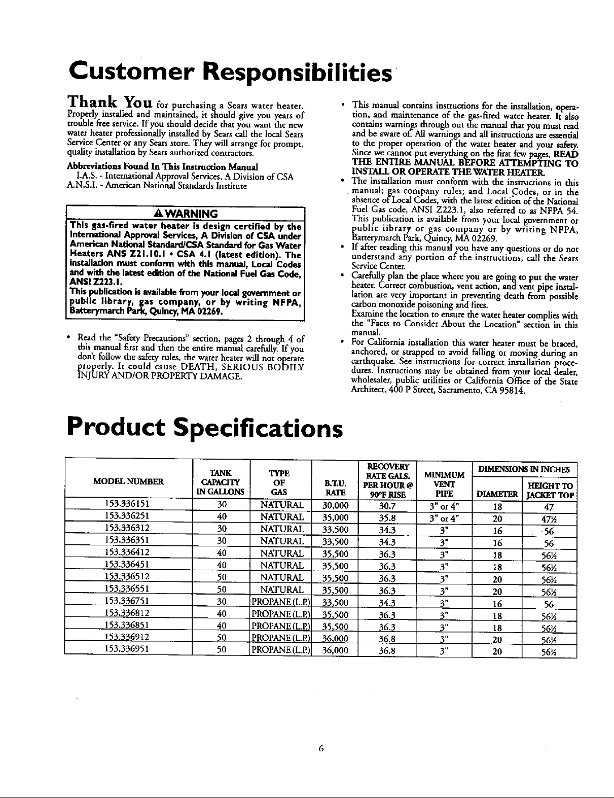
Product Specifications
MODEL NUMBER
153.336151
153.336251
153.336312
153.336351
153.336412
153.336451
153.336512
153.336551
153.336751
153.336812
153.336851
153.336912
153.336951
TANK
CAPACITY
IN GALLONS
30
40
30
30
40
40
50
50
30
40
40
50
50
TYPE
OF
GAS
NATURAL
NATURAL
NATURAL
NATURAL
NATURAL
NATURAL
NATURAL
NATURAL
PROPANE (L.EI
PROPANE (L.EI
PROPANE(L.E'
PROPANE(LP.)
PROPANE (L.E)
B._U.
RATE
30,000
35,000
33,500
33,500
35,500
35,500
35,500
35,500
33_500
35,500
35,500
36,000
36,000
RECOVERy
RATEGALLS.
PERHOUR @
90°F RISE
30.7
35.8
34.3
34.3
36.3
36.3
36.3
36.3
34.3
36.3
36.3
36,8
36.8
MINIMUM
VENT
PIPE
3" or 4"
3" or 4"
3"
3"
3"
3"
3"
3"
3"
3"
3"
3"
3"
DIMENSIONS IN INCHES
HEIGHTTO
DIAMETER [ACKETTOP
18 47
20 47½
16 56
16 56
18 56½
18 56½
20 56½
20 56½
16 56
18 56½
18 56½
20 56½
20 56½
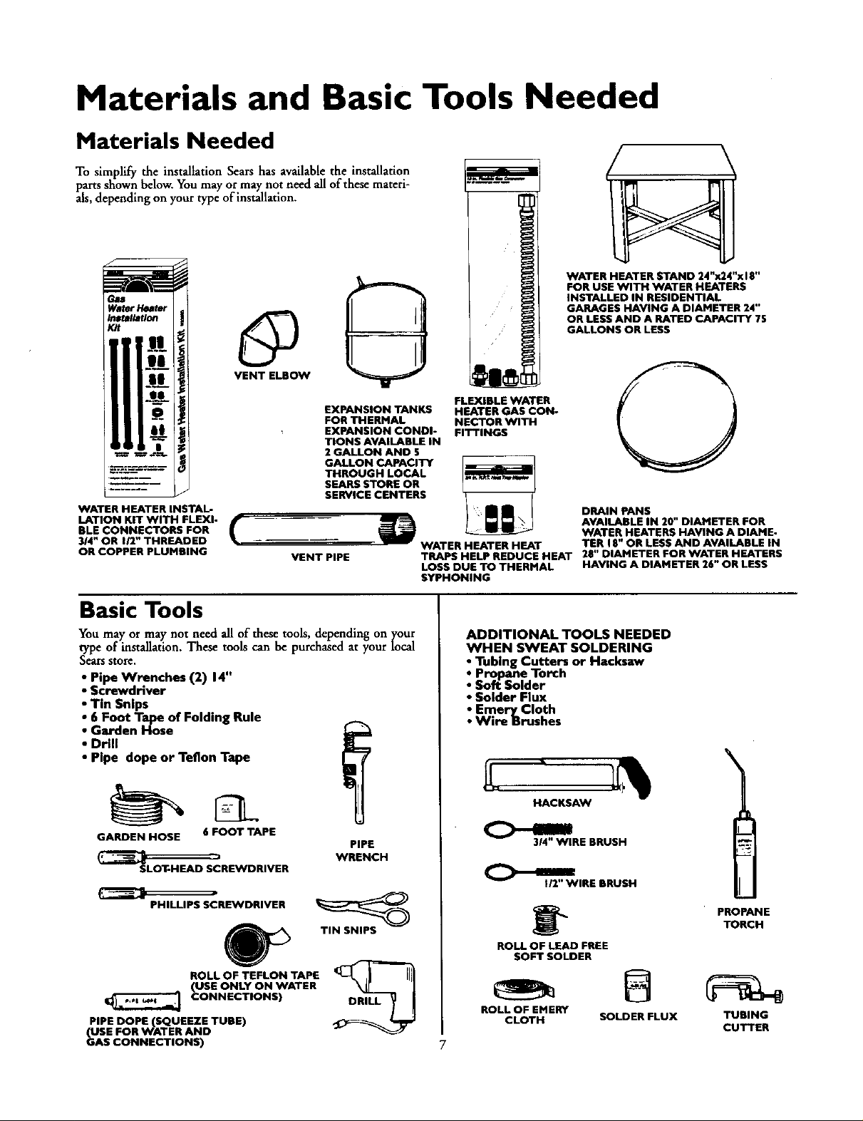
Materials and Basic Tools Needed
Materials Needed
To simplify the installation Sears has available the installation
parts shown below. You may or may not need all of tbese materi-
als, depending on your type of installation.
WATER HEATER STAND 24"x24"x I E"
FOR USE WITH WATER HEATERS
INSTALLED IN RESIDENTIAL
GARAGES HAVING A DIAMETER 24"
OR LESS AND A RATED CAPACITY 7S
GALLONS OR LESS
EXPANSION TANKS
FOR THERMAL
EXPANSION CONDI-
TIONS AVAILABLE IN
2 GALLON AND $
THROUGH LOCAL
SEARS STORE OR
SERVICE CENTERS
WATER HEATER INSTAL-
LATION KIT WITH FLEXI-
BLE CONNECTORS FOR
3/4" OR 112" THREADED
OR COPPER PLUMBING
GALLON CAPACITY
VENT PIPE
Basic Tools
You may or may not need all of these tools, depending on your
type of installation. These tools can be purchased at your local
Sears store,
• Pipe Wrenches (2) 14"
• Screwdriver
• Tin Snips
• 6 Foot Tape of Folding Rule
• Garden Hose
• Drill
• Pipe dope or Teflon Tape
FLEXIBLE WATER
HEATER GAS CON-
NECTOR WITH
FITTINGS
DRAIN PANS
AVAILABLE IN 20" DIAMETER FOR
WATER HEATERS HAVING A DIAME-
WATER HEATER HEAT
TRAPS HELP REDUCE HEAT 28" DIAMETER FOR WATER HEATERS
LOSS DUE TO THERMAL HAVING A DIAMETER 26" OR LESS
SYPHONING
TER 18" OR LESS AND AVAILABLE IN
ADDITIONAL TOOLS NEEDED
WHEN SWEAT SOLDERING
• Tubing Cutters or Hacksaw
• Propane Torch
• Soft Solder
• Solder Flux
• Emery Cloth
• Wire Brushes
\
HACKSAW
GARDEN HOSE 6 FOOT TAPE
SLOT-HEAD SCREWDRIVER
PHILLIPS SCREWDRIVER
ROLL OF TEFLON TAPE
(USE ONLY ON WATER
CONNECTIONS)
PIPE DOPE (SQUEEZE TUBE)
USE FOR WATER AND
_AS CONNECTIONS)
PIPE
WRENCH
TIN SNIPS
314" WIRE BRUSH
C>-.1
ROLL OF LEAD FREE
ROLL OF EMERY
I/2" WIRE BRUSH
SOFT SOLDER
CLOTH SOLDER FLUX
PROPANE
TORCH
TUBING
CUTTER
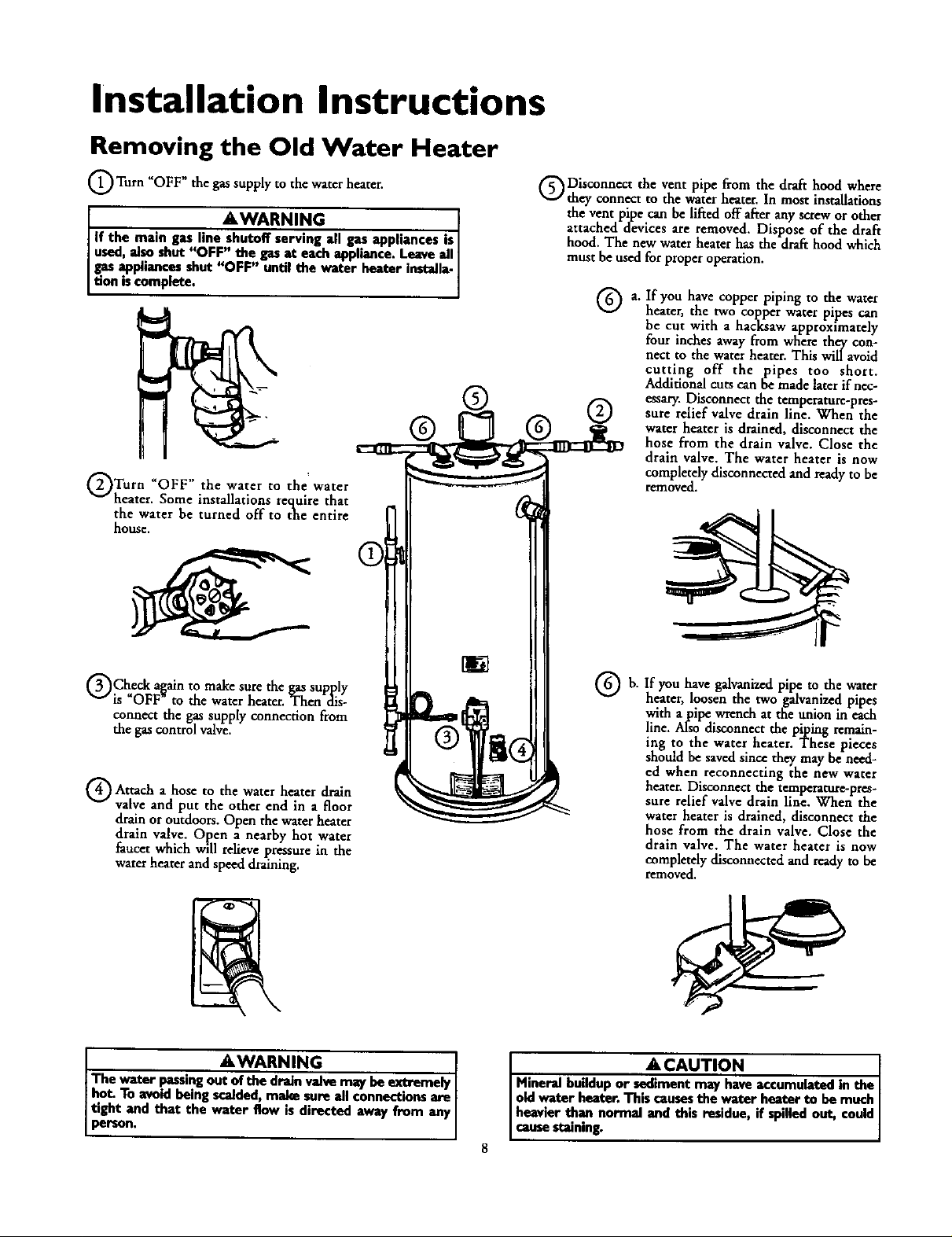
Installation Instructions
Removing the Old Water Heater
Q Turn _OFF _ the gas supply to the water heater.
I *WARNING I
If the main gas line shutoff serving all gas appliances is I
used,al.soshut "OFF" the gas at each appliance. Leave all I
gas appliances shut "OFF" until the water heater installa-
tion iscomplete.
Turn UOFF" the water to water
heater. Some installations require that
the water be turned off to the entire
house,
the'
®
Disconnect the vent pipe from the draft hood where
they connect to the water heater. In most installations
the vent pipe can be lifted off after any screw or other
attached devices are removed. Dispose of the draft
hood. The new water heater has the draft hood which
must be used for proper operation.
a. If you have co er i in to the water
heater, the two copper water pipes can
be cut with a hacksaw approximately
four inches away from where they con-
nect to the water heater. This will avoid
cutting off the pipes too short.
Additional cuts can be made later if nec-
essary. Disconnect the temperature-pres-
sure relief valve drain line. When the
water heater is drained, disconnect the
hose from the drain valve. Close the
drain valve. The water heater is now
completely disconnected and ready to be
removed.
PP PP g
QCheck a_ain to make sure the gas supply
is OFF to the water heater. Then dis-
connect the gas supply connection from
the gas control valve_
Attach a to the water heater drain
valve and put the other end in a floor
drain or outdoors. Open the water heater
drain valve. Open a nearby hot water
faucet which will relieve pressure in the
water heater and speed draining.
The water passingout of the drain valve may beextremely I
hot. To avoidbeing scalded, make sure all connections are [
ttght and that the water flow is directed away from any
person,
hose
AWARNING I
If you have galvanizedpipe to the water
b.
heater, loosen the two galvanized pipes
with a pipe wrench at the union in each
line. A!so disconnect the piping remain-
ing to the water heater. These pieces
should be saved since they may be need-
ed when reconnecting the new water
heater. Disconnect the temperature-pres-
sure relief valve drain line. When the
water heater is drained,disconnect the
hose from the drain valve. Close the
drain valve. The water heater is now
completelydisconnectedand readyto be
removed.
A CAUTION [
Mineral buildup or sediment may haveaccumulated in the I
old Water heater. This causesthe w_er heater to be much I
heavier than normal and this residue, if spilled out, could
causestaining.
Installation Instructions (cont'd)
Facts to Consider About the
Location
You should carefully choose an indoor location for the new
water heater, because the placement is a very important consid-
eration for the safety of the occupants in the building and for
the most economical use of the appliance. This water heater is
not for use in mobile homes or outdoor installation.
Whether replacing an old water heater or putting the water
heater in a new location, the following critical points must be
observed.
• The location selected should be indoors as dose as practical to
the gas vent or chimney to which the water heater vent is
going to be connected, and as centralized with the water pip-
ing system as possible. The water heater, as all water heaters,
will eventually leak. Do not install without adequate drainage
provisions where water flow will cause damage.
ACAUTION
WATER HEATERS EVENTUALLY LEAK: Installation of the
water heater must be accomplishedin sucha manner that if
the tenk or onyconnectionsshouldlank, the how of water will
not causedamagnto the strootur_ Wben soch lucadonscan.
not be avoided,a suitabledrain panshouldbe installedunder
the water heater. Drain pans are availableat your localSears
store. Sucha drain pan must be not greater than 1%inches
dee_ have a minimum length and width of at least 2 inches
IFeater than the water heater dimensionsand must be piped
to an edequato drain.The panmust not restrict€ombustionair
flow. Under no circumstancesisthe manuh_urer or Searsto
be held liablefor any water dam,_e in connection with this
v_or heater.
• The location selection must provide adequate dearances for ser-
vicing and proper operation of the water heater.
AWARNING
Thiswater heater must not be imtelled direcdyon carpe_ng.
Carpeting must be protected by a metal or wood panel
beneath the appliance extending beyondthe full width and
depth of the appliance by at least 3 inches(76.2mm) in any
direction,or if the applianceis installedin an alcoveor closet,
the endre gonr must be coremd by the panel.Failureto heed
this warningmaymsuitina fire hazard.
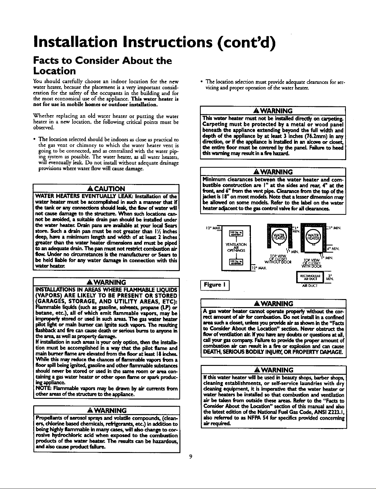
AWARNING
Minimum clearances between the water heater and com-
bustibleconstruction are I" at the sidesand rear, 4" at the
front,and 6,_'from the vontPipe.Claarancefrom the tep oftbe
jacketis 18 onmost model_ Note that alesserdimensionmay
be allowedon some modelL Refer to the label on the water
hez_" edjacont to the gascontrolvaJveforail dearance_
YENTIL&TION
T P_qEW
AWARNING
INSTALLATIONS IN AREAS WHERE FLAMMABLE UQUIDS
_GAPORS) ARE LIKELY TO RE PRESENT OR
ARAGES, STORAGE, AND UTILITY AREAS, ETC),
Flammableliquids(such as gasoBno,solvents,propane(LP) or
butane, etc.), all of which emit flammable vapors, may be
improperlystoredor ased in such_s. The gaswater heart
pilotlight or main burnercanignitesuchvapor_ The resulting
flashbackandEm can causedea_ or seriousburosto anyonein
thearea,aswellasproportydamagn.
If installationin suchareasisyouronlyoption,then the instella-
don must be accomplishedin a way that the pilot flame and
main humorflame are elevated fromtbe tk)or at least 18incheL
Wh_ this ma_reducethe chancesof flammablevaporsfrom a
floorspillbeingignited,gasolineandother flammablesubstances
shouldneverbe storedor usedin the same room or area con-
raininga gaswater heateror other openflame or sparkproduc-
ingappliance.
NOTE: Flammablevaporsmay be drawn byair currentsfrom
other amesofthe structureto theappiiance.
STORED
AWARNING
Propellantsof aerosolspraysand volatile compounds, (clean-
ers, chlorine basedchemicals,refrigerants,etc.) inadditionto
being highlyflammable in many cases,will alsochangeto €or-
rosivo hydrochloric acid when exposed to the combustion
products of the water heater. The resultscan be hazardo_
and alsocauseproductfailure.
Figure I ]
AIR DUCT
AWARNING
A ps water bea_' cannotepera_ i_periy wltbeut the cor-
rect amonnt of elr for comlxe|tion. Do not instellin a confined
areasocha doset, unlessyou provideair esshownin the "Facts
to Comkler About the Location"section.Never obstructthe
flowof ventilationair. If youhwe anydoubtsor quesdomat ail,
cellyanr gas€ompany.Faifureto Ix_vide thepreper amountof
combustionair _m result in a tim or expiosionand can cause
DEATH,SERIOUSBODILY INJURn,OR PROPERTYDAMAGE.
AWARNING
If thiswator heater will be usedin beauty shops,berber shops,
cleaningestablishments, or self-service laundries with dry
cleaningequipment,it is imperative that the water heater or
water heatersbe installedso that combustion and ventilation
air be takan from ontslde thesearees.Refer to the "Facts to
ConsiderAbout the Location"sectionof this manualand aiso
the latestedition of the NationalFuel GasCede, ANSI Z223.1
alsoreferred to as NFPA 54 fur specificsprovidedconcemin
air required.
9
Installation Instructions (cont'd)
Combustion Air and Ventilation
for Appliances Located in
Unconfined Spaces
Unconfined Space is a space whose volume is not less than 50
cubic feet per 1,000 Btu per hour of the aggregate input rating
of all appliances installed in that space. Rooms communicating
directly with the space in which the appliances are installed,
through openings not furnished with doors, are considered a
part of the unconfined space
In unconfined spaces in buildings, infiltration may be adequate
to provide air for combustion, ventilation and dilution of flue
gases. However, in buildings of tight construction (for example,
weather stripping, heavily insulated, caulked, vapor barrier, etc.),
additional air may need to be provided using the methods
described in Combustion Air and Ventilation for Appliances
Located in Confined Spaces, b.
Combustion Air and Ventilation
for Appliances Located in
Confined Spaces
Confined Space is a space whose volume is less than 50 cubic
feet per 1,000 Btu per hour of the aggregate input rating of all
appliances installed in that space.
at.ALL AIR FROM INSIDE BUILDINGS:
(See Page 8 Figure 1, and Figure 2 below)
The confined space shall be provided with two permanent
openings communicating directly with an additional room(s)
of sufficient volume so that the combined volume of all
spaces meets the criteria for an unconfined space. The total
input of all _, utilization equipment installed in the com-
bined space shall be considered in making this determination.
Each opening shall have a minimum free area of one square
inch per 1,000 BTU per hour of the total input rating of all
gas utilization equipment in the confined space, but not less
than 100 square inches. One opening shall commence within
12 inches of the top and one commencing within 12 inches
of the bottom of the enclosure.
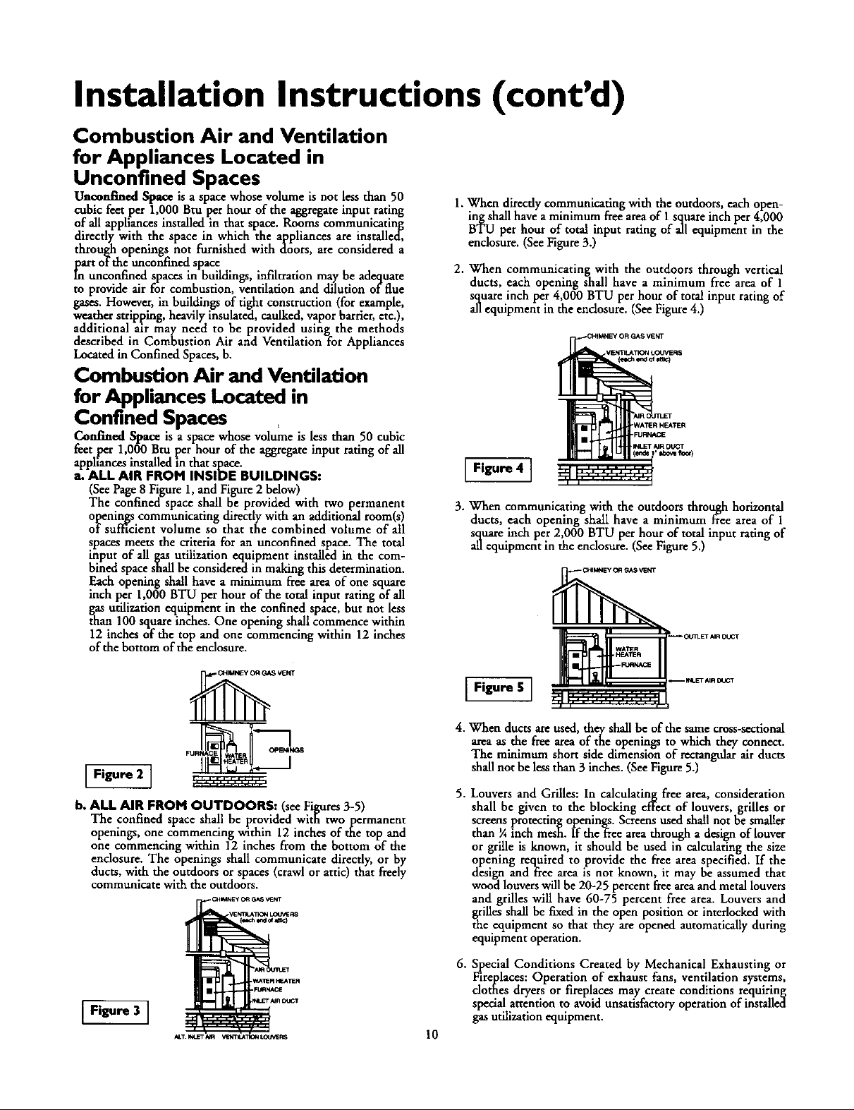
1.When directly communicating with the outdoors,each open-
ing shall have aminimum flee area of 1square inch per 4,000
BTU per hour of total input rating of all equipment in the
enclosure. (SeeFigure3.)
2. When communicating with the outdoors through vertical
ducts, each opening shall have a minimum free area of 1
squareinch per 4,000 BTU per hour of total inputrating of
allequipment in the endosure. (SeeFigure4.)
Figure 4 ]
3. When communicating with the outdoors through horizontal
ducts, each opening shall have a minimum free area of 1
square inch per 2,000 BTU per hour of total input rating of
all equipment in the endosure. (See Figure 5.)
.I_LFT _R DUGT
'Ibo_ IIooq
Figure 2 I
b. ALL AIR FROM OUTDOORS: (seeFigures3-5)
The confined space shall be provided with twopermanent
openings, one commencing within 12 inches of the top and
one commencing within 12 inchesfrom the bottom of the
enclosure. The openings shall communicate directly,or by
ducts,with the outdoorsor spaces(crawl or attic) that freely
communicate with the outdoors.
Figure 3 ]
I Figure S ]
4. When ducts are used, they shall be of the same cross-sectional
area as the free area of the openings to which they connect.
The minimum short side dimension of rectangtdar air ducts
shall not be less than 3 inches. (See Figure 5.)
5. Louvers and Grilles: In calculating free area, consideration
shall be given to the blocking effect of louvers, grilles or
screens protecting openings. Screens used shall not be smaller
than ¼ inch mesh. If theffee area through a design of louver
or grille is known, it should be used in calculating the size
opening required to provide the free area specified. If the
design and free area is not known, it may be assumed that
wood louvers will be 20-25 percent free areaand metal louvers
and grilles will have 60-75 percent free area. Louvers and
grilles shall be fixed in the open position or interlocked with
the equipment so that they are opened automatically during
equipment operation.
6. Special Conditions Created by Mechanical Exhaustingor
Fireplaces: Operation of exhaust fans, ventilation systems,
clothes dryersor fireplaces may create conditions requiring
special attention to avoid unsatisfactoryoperationof installed
gasutilization equipment.
10
 Loading...