


Owners
Manual
FOR POTABLE WATER
HEATING ONLY
NOT SUITABLE FOR
SPACEHEATING
NOT FOR USE IN
MOBILE HONES
Model No.
153.336151 30 Gal. Short
153.336251 40 Gal. Short
153.336312 30 Gal. High Altitude,
153.336351 30 Gal.
153.336412 40 Gal. High Altitude
153.336451 40 Gal.
153.336512 50 Gal. HighAltitude
153.336551 50 Gal.
153.336751 30 Gal. Propane (LE)
153.336812 40 Gal. Propane (LP.)
HighAltitude
153.336851 40 Gal. Propane (I_E)
153.336912 50 Gal. Propane (LP.)
High Altitude
153.336951 50 Gal. Propane (LP.)
POWER MISER M6
GAS WATER HEATER
• Safety Instructions
• Installation
• Operation
For Your Safety
AN ODORANT IS ADDED TO THE GAS USED BY THIS
WATER HEATER
WARNING: If the information in these instructions are not fol- I
lowed exactly, a fire or explosion may result, causing property I
damage, personal injury or death• I
-Do not store or use gasoline or other flammable vapors and liquids
,n the vicinity of th's or any other apprance.
-WHAT TO DO IF YOU SMELL GAS
• Do not try to light any appliance.
• Do not touch any electr,'cal switch; do not use any phone in your
building• . .
Immediately call your gas supplier from a neighbors phone.
Follow the gassupplier'sinstructions.
If you can not reach your gas suppl,er, call the fire department.
-Instal.lation and service must be performed by a qualified installer,
serv,ce agency or the gas suppl,er.
• Care and Maintenance
• Troubleshooting
• Parts List
Caution:
Read and Follow
All Safety Rules and
Operating Instructions
Before First Use of
This Product.
Savethis Manual for Future Reference.
Sears, Roebuck and Co., Hoffman Estates, IL 60179 U.S.A.
Improper installation, adjustment, alteration, service or maintenance can
cause DEATH, SERIOUS BODILY INJURY, OR PROPERTY DAMAGE. Refer to
I atWARNING
this manual for assistance or consult the local Sears Service Center or gas util-
it), for further information.
Flammable vapors may be drawn by air currents from other areas of the
structure to this appliance.
I AWARNING ]
READ THE GENERAL SAFETY SECTION BEGINNING ON INSIDE COVERB
AND THEN THIS ENTIRE MANUAL BEFORE INSTALLING OR OPERAT-
ING THIS WATER HEATER.
AWARNING 1
Safety Precautions
AWARNING I
Improper installation, adjustment, alteration, service or I
maintenance can cause DEATH, SERIOUS BODILY I
INJURY, OR PROPERTY DAMAGE. Refer to this manu-
al for assistance or consult your local Sears Service
Center for further nformat on.
AWARNING
WATER HEATERS EQUIPPED FOR ONE TYPE GAS
ONLY: This water heater is equipped for one type gas
only. Check the model rating plate near the gas control
valve for the correct gas. DO NOT USE THIS WATER
HEATER WITH ANY GAS OTHER THAN THE ONE
SHOWN ON THE MODEL RATING PLATE. Failure to
usethe correct gascan cause problems which can result in
DEATH, SERIOUS BODILY INJURY, OR PROPERTY
DAMAGE. If you have any questions or doubts consult
your gassupplier or localutility.
_,WARNING
INSTALLATIONS IN AREAS WHERE FLAMMABLE LIQ-
UIDS (VAPORS) ARE LIKELY TO BE PRESENT OR
STORED (GARAGES, STORAGE, AND UTILITY AREAS,
ETC): Flammable liquids (such as gasoline, solvents,
propane (LP) or butane, etc.), all of which emit flammable
vapors, may be improperly stored or used in such areas.
The gas water heater pilot light or main burner can ignite
such vapors. The resulting flashback and fire can cause
death or serious burns to anyone in the area, as well as
property damage.
If installation in such areas is your only option, then the
installation must be accomplished in a way that the pilot
flame and main burner flame are elevated from the floor
at least 18 inches. While this may reduce the chancesof
flammable vapors from a floor spill being ignited, gasoline
and other flammable substancesshould never be stored or
used in the same room or area containing a gas water
heater or other open flame or spark producing appliance.
NOTE: Flammable vapors may be drawn by air currents
from other areas of the structure to the appliance.
AWARNING
If this water heater will be used in beauty shops, barber
shops, cleaning establishments, or serf-service laundries
with dry cleaning equipment, it is imperative that the
water heater or water heaters be installed so that com-
bustion and ventilation air be taken from outside these
areas. Refer to the "Locating The New Water Heater"
section of this manual and also the latest edition of the
National Fuel Gas Code, ANSI Z223.1, also referred to as
NFPA 54 for specificsprovided concerningair required.
AWARNING
A fire can start if combustiblematerialssuchasclothing
cleaningmaterials,or flammableliquidsare placedagainst
or nextto thewater heater.
&WARNING
At the time of manufacture this water heater was pro-
vided with a combination temperature-pressures relief
valve certified by a nationally recognized testing labora-
tory that maintains periodic inspection of production of
listed equipment or materials, as meeting the require-
ments for Relief Valves and Automatic Gas Shutoff
Devices for Hot Water Supply Systems, and the latest
edition of ANSI Z21.22 and the code requirements of
ASME. If replaced, the valve must meet the require-
ments of local codes, but not less than a combination
temperature and pressure relief valve certified as meet-
ing the requirements for Relief Valves and Automatic
Gas Shutoff Devices for Hot Water Supply Systems,
ANSI Z21.22 bya nationally recognized testing laborato-
ry that maintains periodic inspection of production of
listed equipment or materials.
The valve must be marked with a maximum set pressure
not to exceed the marked hydrostatic working pressure
of the water heater (150 Ibs.lsq. in.) and a discharge
capacity not less than the water heater input rate as
shown on the model rating plate. (Electric heaters -
watts divided by 1000 x 3415 equal BTUIHr. rate.)
Your local jurisdictional authority, while mandating the
use of a tempereture-pressure relief valve complying
with ANSI Z21.22 and ASME, may require a valve model
different from the one furnished with the water heater.
Compliance with such local requirements must be satis-
fied by the installer or end user of the water heater with
a locally prescribed temperature-pressure relief valve
installed in the designated opening in the water heater in
placeof the factory furnished valve.
For safe operation of the water heater, the relief valve
must not be removed from it's designated opening or
plugged.
The temperature-pressure relief valve must be installed
directly into the fitting of the water heater designated for
the relief valve. Position the valve downward and provide
tubing so that any discharge will exit only within 6 inches
above, or at any distance below the structural floor. Be
certain that no contact is made with any live electrical
part. The discharge opening must not be blocked or
reduced in size under any circumstances. Excessive
length, over 30 feet, or use of more than four elbows carl
cause restriction and reduce the discharge capacity of
the valve.
No valve or other obstruction is to be placed between
the relief valve and the tank. Do not connect tubing
directly to discharge drain unless a 6" air gap is provided.
To prevent bodily injury, hazard to life, or property dam-
age, the relief valve must be allowed to discharge water
in quantities should circumstances demand, if the dis-
charge pipe is not connected to a drain or other suitable
means, the water flow may cause property damage.
The Discharge Pipe:
Must not be smaller in size than the outlet pipe size of
the valve, or have any reducing couplings or other
restrictions.
Must not be pluggedor blocked.
Must be of material listed for hot water distribution.
Must be installed so as to allow complete drainage of
both the temperature-pressure relief valve, and the
discharge pipe.
Must terminate at an adequate drain.
Must not have any valve between the relief valve and
tank.
Safety Precautions
A,WARNING
A gas water heater cannot operate properlywithout the
correct amount of air for combustion. Do not install in a
confined area such a closet, unless you provide air as
shown in the "Locating The New Water Heater" section.
Never obstruct the flow of ventilation air. If you have any
doubts or questions at all, call your gas company. Failure
to provide the proper amount of combustion air can result
in a fire or explosion and can cause DEATH, SERIOUS
BODILY INJURY,OR PROPERTY DAMAGE.
AWARNING
HOTTER WATER CAN SCALD: Water heaters are
intended to produce hot water. Water heated to a tom-
perature which will satisfy clothes washing, dish washing,
and other sanitizing needs can scald and permanently
Injure you upon contact. Some people are more likely to
be permanently injured by hot water than others. These
include the elderly, children, the infirm, or physically/men.
tally handicapped. If anyone using hot water in your home
fits into one of these groups or if there is a local code or
state law requiring acertain temperature water at the hot
water tap, then you must take special precautions. In addi-
tion to usingthe lowest possibletemperature setting that
satisfiesyour hot water needs, a means suchas a mixing
valve, should be usedat the hot water taps used by these
people or at the water heater. Mixing valves are available
at plumbing supply or hardware stores. Follow manufac-
turors instructions for installation of the valves. Before
changingthe factory setting on the thermostat, read the
"Temperature Regulation" section in this manual.
AWARNING
Soot build-up indicates a problem that requires correc-
tion before further use. Turn "off" gas to water heater
and leave "off" until repairs are made, because failure to
correct the cause of the sooting can result in a fire or
explosion causing DEATH, SERIOUS BODILY INJURY,
OR PROPERTY DAMAGE.
&WARNING
Thiswater heater must not be installeddirectlyon car-
peting. Carpetingmustbe protectedby a metal or wood
panel beneaththe applianceextendingbeyondthe full
width and depth of the appliance by at least 3 inches
(76.2mm) in any direction,or if the applianceisinstalled
inanalcoveorcloset,the entirefloormustbe coveredby
the panel. Failure to heed this warningmay result in a
fire hazard.
AWARNING
VENT DAMPERS - Any vent damper, whether it is operat-
ed thermally or otherwise must be removed if its use
inhibitsproper drafting of the water heater.
Thermally Operated Vent Dampers: Gas-fired water
heaters having thermal efficiency in excess of 80% may
treduce a relatively low flue gas temperature. Such tem-
mratures may not be high enough to properly open ther-
mally operated vent dampers, This would causespillageof
flue gasesand may causecarbon monoxide poisoning.
Vent dampers must bear evidence of certification as com-
plying with the latest edition of American National
Standard ANSI Z21.68 (ANSI Z21.66 & 67, respectively,
cover electrically and mechanically actuated vent
dampers), Before installation of any vent damper, consult
mar local Sears Service Center or the gas utility for fur-
ther information,
AWARNING
•The appliance and its individualshutoff valve must be dis-
connected from the gassupply piping system during any
pressure testing of the gas system at test pressures in
excessof I/2 pound per squareinch (3.SkPa).
• The appliance must be isolated from the gas supplypip-
ing system by closing its individual manual shutoff valve
during any pressure testing of the gas supplypiping sys-
tem at test pressures equal or less than I/2 pound per
square inch(3.SkPa).
_,WARNING
BEFORE LIGHTING [PROPANE (L.P.) GAS WATER
HEATERS]: Propane (L.R) gasis heavier than air. Should
there be a leak in the system, the gas will settle near the
ground. Basements, crawl spaces, skirted areas under
mobile homes (even when ventilated), closets and areas
below ground level will serve as pocketsfor the accumula-
tion of this gas. Before a_empting to light or relight the
water heater's pilot or turning on a nearby electrical light
switch, be absolutely sure there is no accumulated gas in
the area_Search for odor of gas by sniffing at ground level
in the vicinity of the appliance, It"odor is detected, follow
steps indicated at "For Your Safety" on the cover page of
this manual then leave the premises.
AWARNING
Chemical vapor corrosion of the flue and vent system
may occur if air for combustion contains certain chemical
vapors. Spray can propellants, cleaning solvents,refrigera-
tor and air conditioner refrigerants, swimming pool
chemicals, calcium and sodium chloride, waxes, bleach,
and process chemicals are typical compounds which are
potentially corrosive.
AWARNING
Obstructed or deteriorated vent systems may present a
serious health risk or asphyxation.
Safety Precautions continued on page4
3
Safety Precautions
AWARNING 1
The water heater with draft hood Installed must be prop-/
eriy vented to a chimney which terminates outdoors.|
Never operate the water heater unless It is vented to the/
outdoors and has adequate air supply to avoid risks ofl
improper operation, explosion or asphyxiation. |
AWARNING
Minimum clearances between the water heater and com-
basttbleconstruction are I" at the sidesand rear, 4" at the
front,and 6,_'filxlnthe ventI_e. CJearancefrom the top of the
jacketis 18 on most medels. Note thet a lesser dimansion m_
be allowedon some models. Refer to the label on the vra_
heeteradjacentto the gascantrolvalvefor ail deanmce_
AWARNING [
Do not use this appliance if any part of it has been under I
water. Immediately call a Sears Service Technician to [
inspectthe appliance andto replace the gas control or any
part of the burner systemwhich kesbeen under water.
_WARNING
HYDROGEN GAS: Hydrogen gascan be produced In a hot
water system that hasnot been usedfor a long period of
time (generally two weeks or more). Hydrogen gas is
extremely flammable and explosive. To prevent the possl-
bility of Injury under these conditions, we recommend the
hot water faucet be opened for several minutes at the
kitchen sink before any electrical appliances which are
connected to the hot water system are used (suchas a dis-
hwasber or washing machine). If hydrogen gas is present,
there will probably be an unusual sound similar to air
escaping through the pipe as the hot water faucet is
opened. There must be no smoking or open game near
the faucet at the time it is open.
ACAUTION
WATER HEATERS EVENTUALLY LEAKJ IostaJlation of
the water heater must be accomplished insuch a manner
that If the tank or any connections should leak, the flow of
water will not cause damage to the structure. When such
locations cannot be uolded, a suitable drsJn pan should
be Installed under the water heater. Drain pansare avail.
able at your Iocai Sears store. Such a drain pan must be
not greater than I I/2 inches deep, have a minimum
length and width of at least 2 inches greater than the
water heater dimensions and must be piped to an ade-
quate drain. The pan must not restrict combustion air
flow. Under no circumstances is the manufacturer or
Sears to be held liable for any water damage in €onnec-
tion with this water heater.
AWARNING
INSULATING JACKETS: When Installing an external
water heater Insulation jacket on a gas water heater:
DO NOT cover the temperutoro-pressure rellof veJve.
DO NOT put insulation over any part of the top of the
gaswater heater.
DO NOT put insulation over the gascontrol valve or gas
control vaivelburner cover, or any access areas to the
burner.
DO NOT let insulation around the gas water heater to
get within 8 inches of the floor (air must get to the
burner).
DO NOT cover or remove operating instructions, and
safety related warning labels and materials affixed to the
water heater.
Failure to heed this will result in the possibilityof a fire or
explosion.
Table of Contents
Safety Precautions ............................................................................................................................................2-4
Table of Contents ................................................................................................................................................5
Customer Responsibilities .......................................................................................................................6
Product Specifications ..................................................................................................................................6
Materials and Basic Tools Needed ..............................................................................................
Materials Needed .....................................................................................................................................................................
Basic Tools ...............................................................................................................................................................................
Installation Instructions ........................................................................................................................s-16
Removing the Old Water Heater ............................................................................................................................................... 8
Facts to Consider About the Ix_tion ....................................................................................................................................... 9
Combmtlon Ai.rand Ventilation for Appliances in Unconfined Spaces ................................................................................... 10
C_mbmtlon Air and Ventilation for Appliances in Confined Spaces ....................................................................................... 10
Water Piping ........................................................................................................................................................................... 11
Teraperamre-Prc_ure Reliff Valve........................................................................................................................................... 12
Filling the Water Heater .......................................................................................................................................................... 13
Venting .............................................................................................................................................................................. 13-14
Gas Piping ......................................................................................................................................................................... 14-15
Imtallation Checklist .............................................................................................................................................................. 16
0 eratin Instructions 17-19
_"_ting ............................................................................................................................................................................. 17-18
Temperatm_ Regulation .......................................................................................................................................................... 19
g .........................................................................................................................
Service and Adjustment ......................................................................................................................20-21
Tank (Sediment) Cleaning ...................................................................................................................................................... 20
Venting System Inspection ...................................................................................................................................................... 20
Burner Inspection ................................................................................................................................................................... 20
Burner Cleaning ..................................................................................................................................................................... 20
L.E Gas Control Valve & Burner Assembly ............................................................................................................................ 20
Draining ................................................................................................................................................................................. 21
Temperature-Pressure Relief Valve Operation .......................................................................................................................... 21
Drain Valve Washer Replacement ........................................................................................................................................... 21
Housekeeping ......................................................................................................................................................................... 21
Service .................................................................................................................................................................................... 21
Troubleshootin Guide 22-25
Start Up Condltiom .......................................................................................................................................................... 22-23
Thermal Expansion .............................................................................................................................................................. 22
Strange Sounds ..................................................................................................................................................................... 22
Condensation ....................................................................................................................................................................... 23
Smoke/Odor ......................................................................................................................................................................... 23
Operational Conditions ..................................................................................................................................................... 23-24
Smelly Water ........................................................................................................................................................................ 23
Air m Hot Warer Faucets ................................................................................................................................................... 23
High Temperature Shut Off System ...................................................................................................................................... 24
Not Enough Hot Water ........................................................................................................................................................ 24
Water is too Hot ................................................................................................................................................................... 24
Leakage Checkpoints .............................................................................................................................................................. 25
g ........................................................................................................................
PartsOrder List...............................................................................................................................................2s-31
5
Customer Responsibilities
Thank You for purchasinga Sears water heater.
Properly installed and maintained, it should give you years of
trouble free service. If you should decide teat you want the new
water heater professionally installed by Sears call the local Sears
Service Center or any Sears store. They will arrange for prompt,
quality installation by Sears authorized contractors.
Ahhreviatiom Fomad In This IJastrttctlou Man.a1
I.A.S. - International Approval Services, A Division of CSA
A.N.S.I. - American National Standards Institute
AWARNING
This gas-fired water heater is design certified by the
International Approval Services, A Division of CSA under
American National Standard/CSA Standard for Gas Water
Heaters AN$ Z21.10.1 ° CSA 4.1 (latest edition). The
installation must conform with this manual, Local Codes
and with the latest edition of the National Fuel Gas Code,
ANSI Z223.1:
This publicatmn is avallaldefrom your local government or
public library, gas company, or by writing NFPA,
Batterymarch Park, Quincy,MA 02269.
• Read the _Safety Precautions" section, pages 2 through 4 of
this manual first and then the entire manual carefully. If you
don't follow the safety rules, the water heater will not operate
_Nroperly. It could cause DEATH, SERIOUS BODILY
.JURYAND/OR PROPERTY DAMAGE.
• This manual contains instructions fur the installation, opera-
tion, and maintenance of the gas-fired water heater. It also
contains warnings through out the manual that you must read
and be aware of. All warnings and all instructions ire essential
to the proper operation of the water heater and your safety.
Since we cannot put everything on the first f_w pages, READ
THE ENTIRE MANUAL BEFORE ATTEMPTING TO
INSTALL OR OPERATE THE WATER HEATER.
• The installation must conform with the instructions in this
• manual; gas company rules; and Local Codes, or in the
absence of Local Codes, with the latest edition of the National
Fuel Gas code, ANSI Z223.1, also referred to as NFPA 54.
This publication is available from your local government or
public library or gas company or by writing NFPA,
Batrerymarch Park, Quincy, MA 02269.
• If after reading this manual you have any questions or do not
understand any portion of the instructions, call the Sears
Service Center.
• Carefully plan the place where you are going to put the water
heater. Correct combustion, vent action, and vent pipe instal-
lation are very imporiam in pte-aeming death from possible
carbon monoxide poisoning and fires.
Examine the location to ensure the water heater complies with
the OFacts to Consider About the Location" section in this
nlRnual.
• For California installation this water heater must be braced,
anchored, or strapped to avoid falling or moving during an
earthquake. See instructions for correct installation proce-
dures. Instructions may be obtained from ),our local dealer,
wholesaler, public utilities or California Office of the State
Architect, 400 P Street, Sacramento, CA 95814.
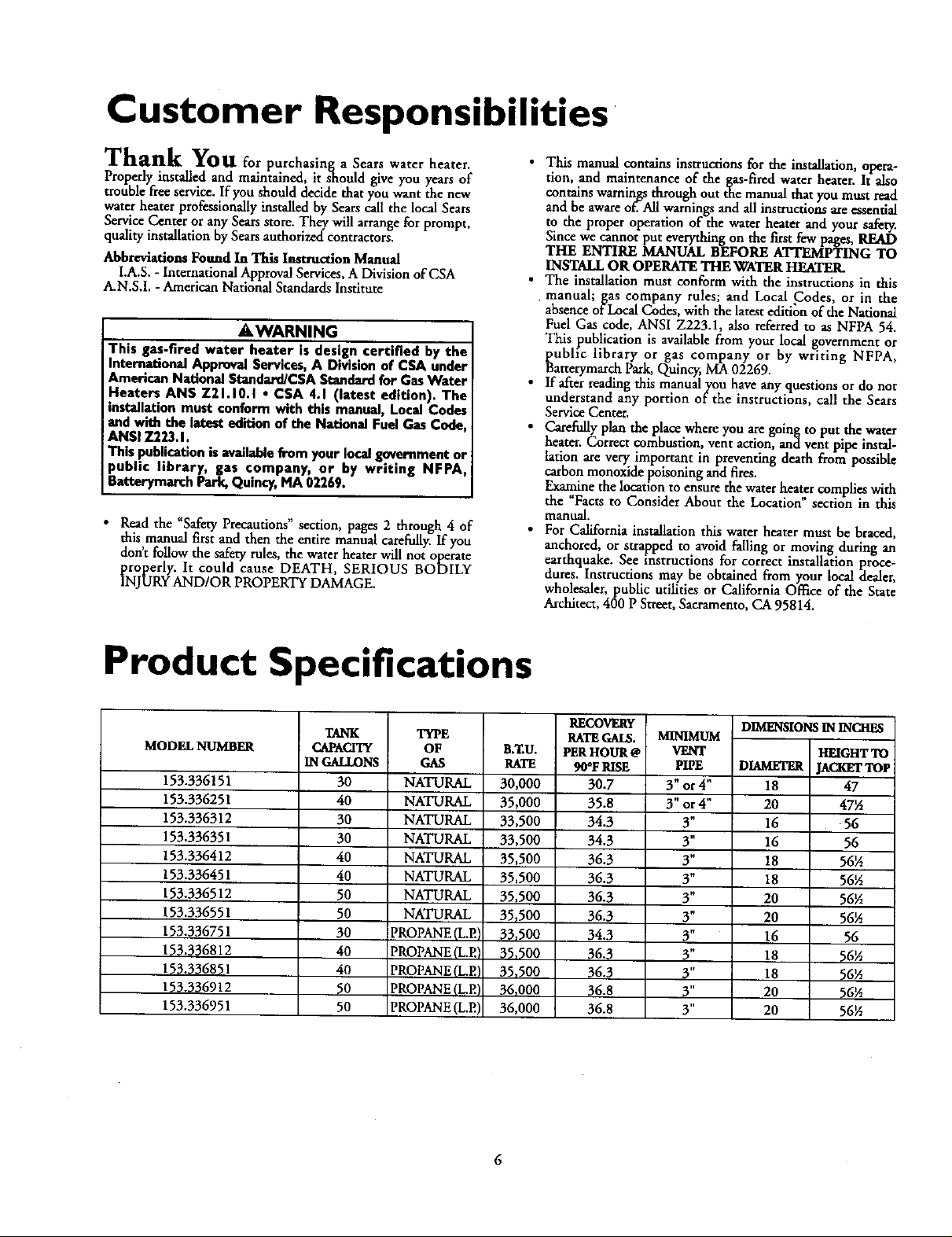
Product Specifications
MODEL NUMBER
153.336151
153.336251
153.336312
153.336351
153.336412
153.336451
153.336512
153.336551
153.336751
153.336812
153.336851
153.336912
153.336951
TANK
CAPACITY
IN GALLONS
30
40
30
30
40
40
50
50
30
40
40
50
50
TYPE
OF
GAS
NATURAL
NATURAL
NATURAL
NATURAL
NATURAL
NATURAL
NATURAL
NATURAL
PROPANE (L.EI
PROPANE (L.EI
PROPANE(L.E'
PROPANE(LP.)
PROPANE (L.E)
B._U.
RATE
30,000
35,000
33,500
33,500
35,500
35,500
35,500
35,500
33_500
35,500
35,500
36,000
36,000
RECOVERy
RATEGALLS.
PERHOUR @
90°F RISE
30.7
35.8
34.3
34.3
36.3
36.3
36.3
36.3
34.3
36.3
36.3
36,8
36.8
MINIMUM
VENT
PIPE
3" or 4"
3" or 4"
3"
3"
3"
3"
3"
3"
3"
3"
3"
3"
3"
DIMENSIONS IN INCHES
HEIGHTTO
DIAMETER [ACKETTOP
18 47
20 47½
16 56
16 56
18 56½
18 56½
20 56½
20 56½
16 56
18 56½
18 56½
20 56½
20 56½
Materials and Basic Tools Needed
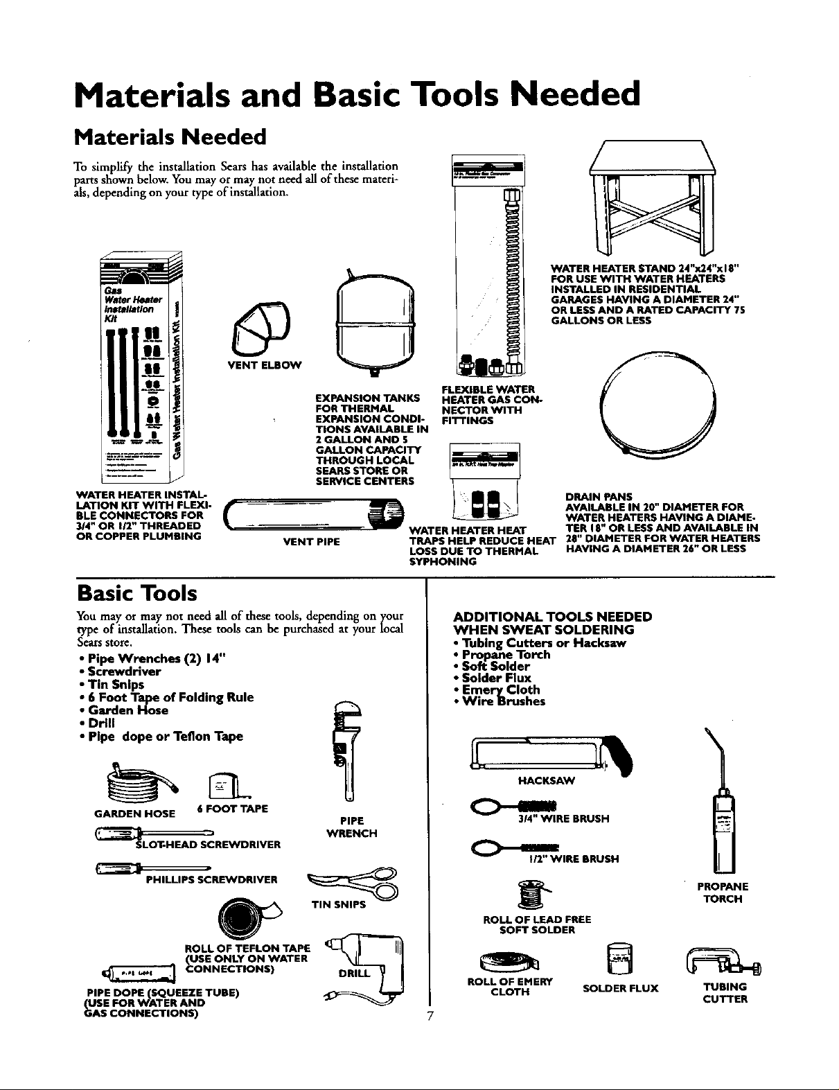
Materials Needed
To simplify the installation Sears has available the installation
parts shown below. You may or may not need all of tbese materi-
als, depending on your type of installation.
WATER HEATER STAND 24"x24"x I E"
FOR USE WITH WATER HEATERS
INSTALLED IN RESIDENTIAL
GARAGES HAVING A DIAMETER 24"
OR LESS AND A RATED CAPACITY 7S
GALLONS OR LESS
EXPANSION TANKS
FOR THERMAL
EXPANSION CONDI-
TIONS AVAILABLE IN
2 GALLON AND $
THROUGH LOCAL
SEARS STORE OR
SERVICE CENTERS
WATER HEATER INSTAL-
LATION KIT WITH FLEXI-
BLE CONNECTORS FOR
3/4" OR 112" THREADED
OR COPPER PLUMBING
GALLON CAPACITY
VENT PIPE
Basic Tools
You may or may not need all of these tools, depending on your
type of installation. These tools can be purchased at your local
Sears store,
• Pipe Wrenches (2) 14"
• Screwdriver
• Tin Snips
• 6 Foot Tape of Folding Rule
• Garden Hose
• Drill
• Pipe dope or Teflon Tape
FLEXIBLE WATER
HEATER GAS CON-
NECTOR WITH
FITTINGS
DRAIN PANS
AVAILABLE IN 20" DIAMETER FOR
WATER HEATERS HAVING A DIAME-
WATER HEATER HEAT
TRAPS HELP REDUCE HEAT 28" DIAMETER FOR WATER HEATERS
LOSS DUE TO THERMAL HAVING A DIAMETER 26" OR LESS
SYPHONING
TER 18" OR LESS AND AVAILABLE IN
ADDITIONAL TOOLS NEEDED
WHEN SWEAT SOLDERING
• Tubing Cutters or Hacksaw
• Propane Torch
• Soft Solder
• Solder Flux
• Emery Cloth
• Wire Brushes
\
HACKSAW
GARDEN HOSE 6 FOOT TAPE
SLOT-HEAD SCREWDRIVER
PHILLIPS SCREWDRIVER
ROLL OF TEFLON TAPE
(USE ONLY ON WATER
CONNECTIONS)
PIPE DOPE (SQUEEZE TUBE)
USE FOR WATER AND
_AS CONNECTIONS)
PIPE
WRENCH
TIN SNIPS
314" WIRE BRUSH
C>-.1
ROLL OF LEAD FREE
ROLL OF EMERY
I/2" WIRE BRUSH
SOFT SOLDER
CLOTH SOLDER FLUX
PROPANE
TORCH
TUBING
CUTTER
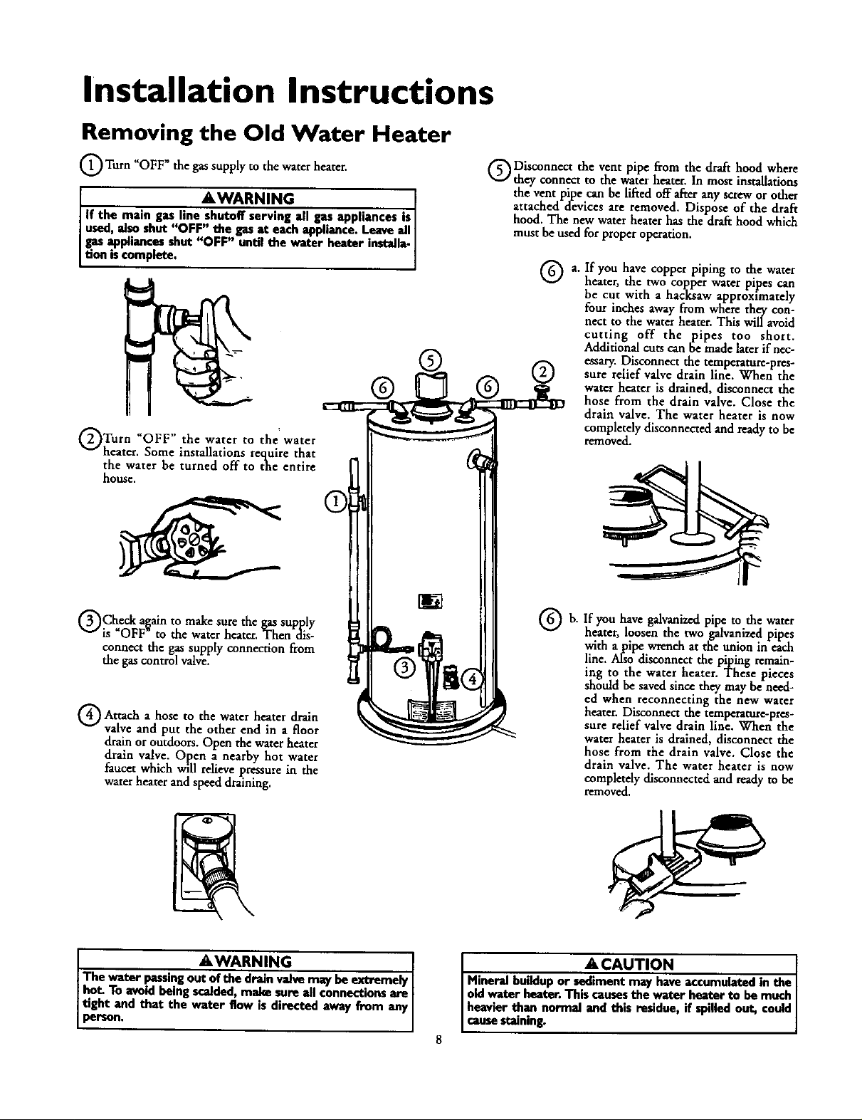
Installation Instructions
Removing the Old Water Heater
Q Turn _OFF _ the gas supply to the water heater.
I *WARNING I
If the main gas line shutoff serving all gas appliances is I
used,al.soshut "OFF" the gas at each appliance. Leave all I
gas appliances shut "OFF" until the water heater installa-
tion iscomplete.
Turn UOFF" the water to water
heater. Some installations require that
the water be turned off to the entire
house,
the'
®
Disconnect the vent pipe from the draft hood where
they connect to the water heater. In most installations
the vent pipe can be lifted off after any screw or other
attached devices are removed. Dispose of the draft
hood. The new water heater has the draft hood which
must be used for proper operation.
a. If you have co er i in to the water
heater, the two copper water pipes can
be cut with a hacksaw approximately
four inches away from where they con-
nect to the water heater. This will avoid
cutting off the pipes too short.
Additional cuts can be made later if nec-
essary. Disconnect the temperature-pres-
sure relief valve drain line. When the
water heater is drained, disconnect the
hose from the drain valve. Close the
drain valve. The water heater is now
completely disconnected and ready to be
removed.
PP PP g
QCheck a_ain to make sure the gas supply
is OFF to the water heater. Then dis-
connect the gas supply connection from
the gas control valve_
Attach a to the water heater drain
valve and put the other end in a floor
drain or outdoors. Open the water heater
drain valve. Open a nearby hot water
faucet which will relieve pressure in the
water heater and speed draining.
The water passingout of the drain valve may beextremely I
hot. To avoidbeing scalded, make sure all connections are [
ttght and that the water flow is directed away from any
person,
hose
AWARNING I
If you have galvanizedpipe to the water
b.
heater, loosen the two galvanized pipes
with a pipe wrench at the union in each
line. A!so disconnect the piping remain-
ing to the water heater. These pieces
should be saved since they may be need-
ed when reconnecting the new water
heater. Disconnect the temperature-pres-
sure relief valve drain line. When the
water heater is drained,disconnect the
hose from the drain valve. Close the
drain valve. The water heater is now
completelydisconnectedand readyto be
removed.
A CAUTION [
Mineral buildup or sediment may haveaccumulated in the I
old Water heater. This causesthe w_er heater to be much I
heavier than normal and this residue, if spilled out, could
causestaining.
Installation Instructions (cont'd)
Facts to Consider About the
Location
You should carefully choose an indoor location for the new
water heater, because the placement is a very important consid-
eration for the safety of the occupants in the building and for
the most economical use of the appliance. This water heater is
not for use in mobile homes or outdoor installation.
Whether replacing an old water heater or putting the water
heater in a new location, the following critical points must be
observed.
• The location selected should be indoors as dose as practical to
the gas vent or chimney to which the water heater vent is
going to be connected, and as centralized with the water pip-
ing system as possible. The water heater, as all water heaters,
will eventually leak. Do not install without adequate drainage
provisions where water flow will cause damage.
ACAUTION
WATER HEATERS EVENTUALLY LEAK: Installation of the
water heater must be accomplishedin sucha manner that if
the tenk or onyconnectionsshouldlank, the how of water will
not causedamagnto the strootur_ Wben soch lucadonscan.
not be avoided,a suitabledrain panshouldbe installedunder
the water heater. Drain pans are availableat your localSears
store. Sucha drain pan must be not greater than 1%inches
dee_ have a minimum length and width of at least 2 inches
IFeater than the water heater dimensionsand must be piped
to an edequato drain.The panmust not restrict€ombustionair
flow. Under no circumstancesisthe manuh_urer or Searsto
be held liablefor any water dam,_e in connection with this
v_or heater.
• The location selection must provide adequate dearances for ser-
vicing and proper operation of the water heater.
AWARNING
Thiswater heater must not be imtelled direcdyon carpe_ng.
Carpeting must be protected by a metal or wood panel
beneath the appliance extending beyondthe full width and
depth of the appliance by at least 3 inches(76.2mm) in any
direction,or if the applianceis installedin an alcoveor closet,
the endre gonr must be coremd by the panel.Failureto heed
this warningmaymsuitina fire hazard.
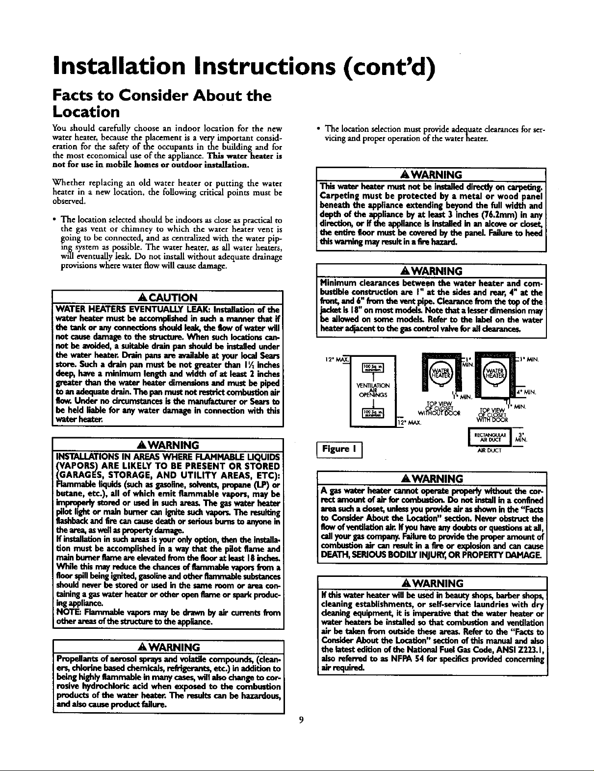
AWARNING
Minimum clearances between the water heater and com-
bustibleconstruction are I" at the sidesand rear, 4" at the
front,and 6,_'from the vontPipe.Claarancefrom the tep oftbe
jacketis 18 onmost model_ Note that alesserdimensionmay
be allowedon some modelL Refer to the label on the water
hez_" edjacont to the gascontrolvaJveforail dearance_
YENTIL&TION
T P_qEW
AWARNING
INSTALLATIONS IN AREAS WHERE FLAMMABLE UQUIDS
_GAPORS) ARE LIKELY TO RE PRESENT OR
ARAGES, STORAGE, AND UTILITY AREAS, ETC),
Flammableliquids(such as gasoBno,solvents,propane(LP) or
butane, etc.), all of which emit flammable vapors, may be
improperlystoredor ased in such_s. The gaswater heart
pilotlight or main burnercanignitesuchvapor_ The resulting
flashbackandEm can causedea_ or seriousburosto anyonein
thearea,aswellasproportydamagn.
If installationin suchareasisyouronlyoption,then the instella-
don must be accomplishedin a way that the pilot flame and
main humorflame are elevated fromtbe tk)or at least 18incheL
Wh_ this ma_reducethe chancesof flammablevaporsfrom a
floorspillbeingignited,gasolineandother flammablesubstances
shouldneverbe storedor usedin the same room or area con-
raininga gaswater heateror other openflame or sparkproduc-
ingappliance.
NOTE: Flammablevaporsmay be drawn byair currentsfrom
other amesofthe structureto theappiiance.
STORED
AWARNING
Propellantsof aerosolspraysand volatile compounds, (clean-
ers, chlorine basedchemicals,refrigerants,etc.) inadditionto
being highlyflammable in many cases,will alsochangeto €or-
rosivo hydrochloric acid when exposed to the combustion
products of the water heater. The resultscan be hazardo_
and alsocauseproductfailure.
Figure I ]
AIR DUCT
AWARNING
A ps water bea_' cannotepera_ i_periy wltbeut the cor-
rect amonnt of elr for comlxe|tion. Do not instellin a confined
areasocha doset, unlessyou provideair esshownin the "Facts
to Comkler About the Location"section.Never obstructthe
flowof ventilationair. If youhwe anydoubtsor quesdomat ail,
cellyanr gas€ompany.Faifureto Ix_vide thepreper amountof
combustionair _m result in a tim or expiosionand can cause
DEATH,SERIOUSBODILY INJURn,OR PROPERTYDAMAGE.
AWARNING
If thiswator heater will be usedin beauty shops,berber shops,
cleaningestablishments, or self-service laundries with dry
cleaningequipment,it is imperative that the water heater or
water heatersbe installedso that combustion and ventilation
air be takan from ontslde thesearees.Refer to the "Facts to
ConsiderAbout the Location"sectionof this manualand aiso
the latestedition of the NationalFuel GasCede, ANSI Z223.1
alsoreferred to as NFPA 54 fur specificsprovidedconcemin
air required.
9
Installation Instructions (cont'd)
Combustion Air and Ventilation
for Appliances Located in
Unconfined Spaces
Unconfined Space is a space whose volume is not less than 50
cubic feet per 1,000 Btu per hour of the aggregate input rating
of all appliances installed in that space. Rooms communicating
directly with the space in which the appliances are installed,
through openings not furnished with doors, are considered a
part of the unconfined space
In unconfined spaces in buildings, infiltration may be adequate
to provide air for combustion, ventilation and dilution of flue
gases. However, in buildings of tight construction (for example,
weather stripping, heavily insulated, caulked, vapor barrier, etc.),
additional air may need to be provided using the methods
described in Combustion Air and Ventilation for Appliances
Located in Confined Spaces, b.
Combustion Air and Ventilation
for Appliances Located in
Confined Spaces
Confined Space is a space whose volume is less than 50 cubic
feet per 1,000 Btu per hour of the aggregate input rating of all
appliances installed in that space.
at.ALL AIR FROM INSIDE BUILDINGS:
(See Page 8 Figure 1, and Figure 2 below)
The confined space shall be provided with two permanent
openings communicating directly with an additional room(s)
of sufficient volume so that the combined volume of all
spaces meets the criteria for an unconfined space. The total
input of all _, utilization equipment installed in the com-
bined space shall be considered in making this determination.
Each opening shall have a minimum free area of one square
inch per 1,000 BTU per hour of the total input rating of all
gas utilization equipment in the confined space, but not less
than 100 square inches. One opening shall commence within
12 inches of the top and one commencing within 12 inches
of the bottom of the enclosure.
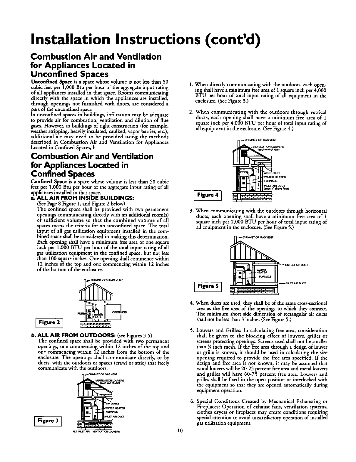
1.When directly communicating with the outdoors,each open-
ing shall have aminimum flee area of 1square inch per 4,000
BTU per hour of total input rating of all equipment in the
enclosure. (SeeFigure3.)
2. When communicating with the outdoors through vertical
ducts, each opening shall have a minimum free area of 1
squareinch per 4,000 BTU per hour of total inputrating of
allequipment in the endosure. (SeeFigure4.)
Figure 4 ]
3. When communicating with the outdoors through horizontal
ducts, each opening shall have a minimum free area of 1
square inch per 2,000 BTU per hour of total input rating of
all equipment in the endosure. (See Figure 5.)
.I_LFT _R DUGT
'Ibo_ IIooq
Figure 2 I
b. ALL AIR FROM OUTDOORS: (seeFigures3-5)
The confined space shall be provided with twopermanent
openings, one commencing within 12 inches of the top and
one commencing within 12 inchesfrom the bottom of the
enclosure. The openings shall communicate directly,or by
ducts,with the outdoorsor spaces(crawl or attic) that freely
communicate with the outdoors.
Figure 3 ]
I Figure S ]
4. When ducts are used, they shall be of the same cross-sectional
area as the free area of the openings to which they connect.
The minimum short side dimension of rectangtdar air ducts
shall not be less than 3 inches. (See Figure 5.)
5. Louvers and Grilles: In calculating free area, consideration
shall be given to the blocking effect of louvers, grilles or
screens protecting openings. Screens used shall not be smaller
than ¼ inch mesh. If theffee area through a design of louver
or grille is known, it should be used in calculating the size
opening required to provide the free area specified. If the
design and free area is not known, it may be assumed that
wood louvers will be 20-25 percent free areaand metal louvers
and grilles will have 60-75 percent free area. Louvers and
grilles shall be fixed in the open position or interlocked with
the equipment so that they are opened automatically during
equipment operation.
6. Special Conditions Created by Mechanical Exhaustingor
Fireplaces: Operation of exhaust fans, ventilation systems,
clothes dryersor fireplaces may create conditions requiring
special attention to avoid unsatisfactoryoperationof installed
gasutilization equipment.
10

Installation Instructions (cont'd)
Water Piping
AWARNING
HOTrER WATER CAN SCALD:Water heatotsam iotendedto
producehot water. Water heated to a tomperatom whichwill i
satisfyclotheswashing,dishweshing_and other suniti_ needs
am scaldend penmnen_ injure you upen contatt. Sornepeo-
4eare morn lilmlyto be permanently injuredby hot w_er _
other_ Theseincludethe elder_ children,the infim-,,or
ly/mentany handicapped,ffenyoneusinghotwater inyour home
Etsintoone ofthese greupsor ifthere isa local€odeor statolaw
requiringacertaintemperature waterat the hotwater _ then
_u musttake specialprecautiom.In additionto usingthe lowest
_ssible temperature settingthat satisfiesyour hot water needs,
_mennssuchasamixlngvalve,thould be usudat the hot water
tapsusedbythese peopleor at the wator heater.Mixingvalves
are availableat plumbingsupplyor hardwarestore_Followman-
ufacturers instructions for installation of the valves. Before
changing the factory setting on the thermostat, read the
'q'empenttureRegulation"section inthis manual
This water heater shall not be connected to any heating systems
or component(s) used with a non-potable water heating
appliance.
If a water heater is installed in a closed water supply system;
such as one having a back-flow preventer, check valve, water
meter with a check valve, etc.., in the cold water supply; means
shall be provided to control thermal expansion. Contact the
local utility or local Sears Service Center on how to control this
situation.
NOTE: To protect against untimely corrosion of hot and
cold water fittings, it is strongly recommended that di..elec-
tric unions or couplings be installed on this water heater
when connected to copper pipe.
• Look at the top cover of the water heater. The cold water
inlet is markedcold. Put two or three turns of teflon tape
around the threaded end of _e threaded-to-sweat coupling
and atuund both ends of the ¾ threaded nipple. Using flexi-
ble connectors, connect the cold water pipe to the coldwater
inlet of the water heater.
NOTE: This water heater is super insulated to minimize
heat 1o. from the tank. Further reduction in heat loss
can be accomplished by insulating the hot water lines
from the water heater.
INSTALLATION COMPLETED USING
SEARS INSTALLATION KIT
FLEXIBLE
WATER
CONNECTORS
HOT OUTLET
TO HOUSE
-?
THREADED TO
SWEAT COUPLING
314"THREADED
COUPLING
HOT
l COLD INLET
THREADED TO
SWEAT
COUPLING
314" THREADED
COUPLING
SHUTOFF
VALVE
WATER LINE
The illustration shows the attachment of the water piping to the
water heater. The water heater is equipped with ¾1,water con-
nec_ions,
NOTE: ff using copper tubing, solder tubing to an adapter
before attaching the adaptor to the cold water inlet connec-
tion. Do not solder the cold water supply line directly to the
cold water inlet. It will harm the dip tube and damage the
tank.
• Look at the top cover of the water heater. The water oudet is
marked hot. Put two or three turns of teflon tape around the
threaded end of the threaded-to-sweat coupling and around
both. ends of the 3A threaded nipple. Using flexible connec-
tors, connect the hot water pipe to the hot water oudet on
the water heater.
11
[]
RELIEFVALVE
DISCHARGE
PIPE (Do not cap
FLOOR DRAIN
PRESSURE
or plug)

Installation Instructions (cont'd)
Temperature-Pressure Relief Valve
&WARNING
At the time of manufacture this water heater was provided
with a combination temperature-pressures relief valve certi-
fied bya nationallyrecognized testing laboratory that main-
tainsperiodic inspectionof productionof listedequipment or
materials, asmeeting the requirements for ReliefValvesand
Automatic Gas Shutoff Devices for Hot Water Supply
Systems,and the latest edition ofANSI Z21.22 and the code
requirements of ASME. If replaced, the valve must meet the
requirements of local codes,but not lessthan a combination
temperature and pressure relief valve certified as meeting
the requirements for Relief Valves and Automatic Gas
ShutoffDevicesfor Hot Water SupplySystems,ANSI Z21.22
by a nationally recognized testing laboratory that maintains
periodic inspection of production of listed equipment or
materials.
The valvemust be marked with amaximum set pressurenot
to exceed the marked hydrostatic working pressure of _le
water heater (150 Ibs./sq.in.) and a discharge capacity not
lessthan the water heater input rate as shownon the model
rating plate. (Electric heaters, watts divided by 1000 x 3415
equal BTU/Hr. rate.)
Your localjurisdictionalauthority, while mandatingthe use of
a temperature-pressure relief valve complying with ANSI
Z21.22 and ASHE, may require a valve model different from
the one furnishedwith the water heater.
Compliance with such local requirements must be satisfied
by the installeror end user of the water heater with alocally
prescribedtemperature.pressure relief valve installed in the
designatedopeninginthe water heater in place oftbe facto-
ry furnishedvalve.
For safeoperation of the water heater, the relief valve must
not beremoved from it's designatedopeningor plugged.
The temperature.pressure relief valve must be installed
directlyinto the fitting of the water heater designatedfor the
relief valve. Position the valvedownward and providetubing
so that any dischargewill exit only within 6 inchesabove, or
at any distance below the structural floor. Be certain that no
contact is made with any live electrical part. The discharge
opening must not be blocked or reduced in size under any
circumstances.Excessivelength, over 30 feet, or use of more
than four elbows can cause restriction and reduce the dis-
chargecapacityofthe valve.
No valve or other obstruction isto be placed between the
relief valve and the tank. Do not connect tubing directly to
dischargedrain unlessa 6" air gap is provided. To prevent
bodily injury, hazard to life, or property damage, the relief
valvemust be allowed to dischargewater in quantities should
circumstancesdemand. If the dischargepipe isnot connect-
ed to a drain or other suitable means, the water flow may
causeproperty damage.
The DischargePipe:
Mustnot be smaller in size than the outlet pipe sizeoftbe
valve, or haveanyreducing couplingsor other restrictions.
Mustnot bepluggedor blocked.
Mustbe of material listedfor hot water distribution.
Mustbe installedso as to allowcomplete drainage of beth
the temperature-pressure relief valve, and the discharge :
pipe.
Mustterminate at an adequatedrain.
Mustnot haveany valvebetween the relief valveand tank.
AWARNING
The temperature-preesure relief valve must be manually
operated at least once a year.Caution shoukl be taken to
emure that (I) no one lsin front of ov around the outlet of
the temperature-pressure rer_f valvedischargeline,and(2)
the water manually discharged will not cause any bodily
injury or property damage because the water may be
extremalyhot
ff after manually operating the valve, it failsto completely
reset and continnesto releasewater, immediately dose the
cold water inlet to the water heater, follow the draining
instructions, and replace the temperature-pressuro relief
valvewith anew one.
HOT
SHUTOFF
VALVE
COLD
PRESSURE
RELIEF VALVE
"DISCHARGE PIPE
(Do not cap or plug)
[]
6" AIR GAP
FLOOR DRAIN
RELIEFVALVEOPENING
At the time of manufacture,thiswater heaterwasprodded_ a combinationtem-
perature-pressurerein _e listed u comp_[ngwiththe standardfor relief valvesand
automaticgasthut_ff devicesfor hotwater supplysystems,ANSI Z21.22. fie< _fe
operationofthewater heater,the relief valvemust not beremo_l fromits designated
pointof insta_l_onorplugged.
Yourlocal jurisdictionalauthori_, whilemandatingthe useof a temperature-pressure
rel_ vahe complyingwithANSIZ21.22 andASME,mayrequireava_ mo_el differont
fromtheo_e furnishedwith _e water heater
Compliancewith suchlocalrequirements must be satisfiedby the installeror end user
of the water heater with a locallyprescdfiedtemperature-pressurereliefvalve_ns_led
inthe designatedopeninginthe water fieate_
See manualheading-_TemperatuR-FressureReliefValves"for installationand mainte-
nanceof reliefval_, dischargeline,andother safetypreca_ons.
]2

Installation Instructions (cont'd)
Filling the Water Heater
A, CAUTION
Neveruset_swater heaterunlessItiscompletelyfilledwith
water.Topreventdamageto thetenk,thetenk mustbefilled
with water. Water must flowfrom the hot water faucet
before',',,minE"ON" gastothewaterheater.
To fill the water heater with water:
• Close the water heater drain valve by turning the handle to
the right (dockwise). The drain valve is on the lower front of
the water heater.
• Open the cold water supply valve to the water heater.
NOTE: The cold water supply valve must be left open
whco th©water heater is in use.
• To insure complete filling of the tank, allow air to exit by
opening the nearest hot water faucet. Allow water to run
until a constant flow is obtained. This will let air out of the
water heater and the piping.
• Check all newwater piping for leaks. Repair as needed.
Venting
AWARNING
VENT DAMPERS. Any vent damper,whether it is opel-dted
thermanyor otherwisemust beremovedIfItsuseinhibitsprop
er draffingofthe water heater.
Thermally Operated Vent Dampem Gas-firedwater heaters
havingthemml e4r_encyIn e_cessof 80%nmyproduce a rela-
t_velylowIluegmtemperature.Suchtemperaturesn_/not be
high enough to properly open thermally operated vent
damperLThiswooldcausespillageofIluegasesandnw cause
c._onrnono_depo_o_
.V_ dampmmu_bmreadeaceofcenmcaeo,ascomping
with the latest editJonof American National StandardANSI
Z21.68 (ANSI 2:21.66& 67, respectively,coverelectricallyand
mechanicallyactuated ventdarnpersgBeforeImtalla_n of any
vent_ €onsultyourlocalSearsServiceCenteror the ips
u_y forfurtherhafonnatk_
AWARNING
To insureproperve_ of this gas-firedwater heater,the
correctventpipediame_r mustbe utilized.Anyadd'talonsor
deledom of othergas appliances ona €ommon ventwi_ this
water heater may ad,na'sely affect the _ of the water
hea_. CoosulttheIoealSearsServiceCentoror gasutilityif
anysuchchangesareplanned.
Forproper ventingin certain installations,a largerdiametervent
pipe may be necessary.Due to greatvariancesin installations,
unforeseeableby the manufacturer of the waterheater,you must
consult your gascompany to aid you in determiningthe proper
ventingfor your waterheater from the vent tables in the latest
edition of the National Fuel Gas Code ANSI Z223.1, also
referredto asNFPA 54.
Checkthe ventingsystemfor signsof obstructionor deterioration
and replaceif needed.
The combustion and ventilationairflow must not be obstructed.
AWARNING J
Oe_uctod or_ ventsystermmay presenta serioos1
health riskor asphy]d_on. I
• Place the draft hood legs in the receiving holes on the top of
the water heater. The legs will snap in the holes to give a tight
fit.
• Place the vent pipe over the draft hood. With the vent pipe in
position, drill a small hole through both the vent pipe and
draft hood. Secure them together with asheet metal screw.
DRAFT HOOD _r IVENT_I J _
,_a_t_. _ f _LF_'j_, T HOOD
VENT TO OUTDOORS OR
CHIMNEY
DRAFT
AWARNING I
TH_v,.._ he_ wlthd__ re.st_ Fo_,'lyI
vented to a chimneywhichterminates outdoors. Never oper- I
ate the wator heater unlessit isventedto the outdoorsand hasI
adequato air supplyto avoidrislmof improper op_q'aflon,explo-I
AWARNING I
The vent pipeftom the wator heater mustbe no lessthan the I
diameter of the draft hood outlet on the water heater, and
I _x_ slopeupwardto the chimney at least ¼ inch per linearI
13

Installation Instructions (cont'd)
Venting (cont'd) Gas Piping
All vent gases must be completely vented to the outdoors of the
structure (dwelling). Installonly the draft hood provided with
the new water heater and no other draft hood.
Vent pipes must be secured at each joint with sheet metal screws.
CHIMNEY
TO
RISE PER LINEAR
RISE?:O .EAR
!
VENT PIPE INSTALLATION
There must be a minimum of 6" dearance between single wall
vent pipe and any combustible materi_l. Fill and seal any clear-
ance between single wall vent pipe and combustible material
with mortar mix, cement, or other noncombustible substance.
For other than single wall, follow vent pipe manufacturer's dear-
ance specifications. To insure a tight fit of the vent pipe in a
brick chimney, seal around the vent pipe with mortar mix
cement.
AWARNING
Failureto haverequireddexrdncesbetweenventpipingand
combustiblematerialwillresultina firehazard.
A WARNING
Besureventpipeisproperlyconnectedto prevonte_capeof
dangerousfluegaseswhichcouldcausedeadly_/x_tion.
AWARNING
Make sure the gas supplied is the same type listed on the
model ra_ng plate. The inlet gaspressuremust not exceed
Ifl.Sin. water column(2,6k_) for natural gasor 13i_ water
column (3.2kPa) for propane (LR) ge_ The minimum inlet
gasprossumlisted on the model rating plate is for the pur-
poseof inputad'FWanont.
AWARNING
Ifthe ges conerolvalve is subjecU_ to pressuresexceeding'A
poundper square inch(3.Side), the damage tO the gascon.
trnl vaJvecould reanlt in a fire or explosionfrom lealdngga_
A W'_RNING 1
If the main gasline shutoffservingaJlgasappliancesk used,|
alsoturn "OFF" the gasat each appliance.Leaveall gasappli-|
antes shutof/until the water heater installationiscomplete. ]
A gas llne of sufficient size must be run to the water heater.
Consult the latest edition of National Fuel Gas Code ANSI
Z223.1, also referred to as NFPA54 and the gascompany concern-
ing pipe size.
There must be:
• A readily accessible manual shut offvalve in the gas supply line
serving the water heater, and
• A drip leg (sediment trap) ahead of the gas control valve to help
prevent dirt and foreign materials from entering the gas control
valve.
• A flexible gas connector or a ground joint union between the
shutoffvalve and control valve to permit servicing of the unit.
AWARNING
Chemicalvaporcorrosionofthe flueandventsystemmay
occurtf air for combustioncomainscert_ chemicalvapor_
Spraycanpropellants,cleaningsolvents,refrigeratorand air
conditionerrefrigerants,swimmingpoolchemicals,calcium
andsodiumchloride,waxes,bleach,andprocesschemicalsare
typicalcompoundswhicharepotenti_dlycorrosive.
Be sure to check allthe gas piping for leaksbefore lighting the
waterheater. Use a soapywater solution, not a match or open
flame.Rinseoffsoapysolutionandwipedry.
Standard Models are for installation up to 3,300 feet above sea
level.
High Altitude Models are for installation from 3,300 to 5,500
_t abo_e sea level.
Ifa standard model is installed above 3,300 feet or a high altitude
model is installed above 5,500 feet, the input rating must be
reduced at the rate of 4 percent for each 1,000 feet above sealevel.
Contact your local Sears Service Center or gas utility for further
information.
14

Installation Instructions (cont'd)
GAS PIPING WITH
The appliance and its gas connection must
beforeplacingthe applianceinoperation.
AWARNING be leak tested
&WARNING
•The applianceand itsindividualshutoffvalve must be discon-
nectedfrom the gassuppiypiping systemduringany pl_sure
testing of the gassystem at test pressuresin excess of
poundper squareinch(3._kl_).
• The appliancemustbeisolatedfrom thegassupplypipingsy_
tem by dosingits individualmanualshutoffvalveduring any
pressuretasl_ngof the gassupplypiping systemat testpres-
suresequalor lessthan _ peued persquare inch(3.5Idea).
FLEXIBLE CONNECTOR
GASSUFFLY
PIPING
GROUNO
UNION(Optional)
T
3" min. _Sedimer_ trap) GAS
FLEXIBLE GAS CONNECTOR
LABELED AS COMPLYING
WITH ANSI STANDING
CONTROLVALVE
AWARNING 1
Use pipe joint compound or teflon tape marked as being[
resistantto the actionof pem_um [Propeue(L.R)] _ |
SEDIMENT TRAP
A sediment trap shall be installed as close to the inlet of the
water heater as practical at the time of water heater installation.
The sediment trap shall be either a tee fitting with a capped nip-
ple in the bottom outlet or other device recognized as an effec-
tive sediment trap. If a tee fitting is used, it shall be installed in
conformance with one of the methods of installation shown
below.
Connecting the gas piping to the gas control valve of the water
heater can be accomplished by either of the two methods shown.
h, WARNING
Contnminants in the gaslinasrow/cause improper operation
of the gascontrol valve th_ may resolt in fire or explosion.
Before attachingthe gasline be sure tl_t all gaspipe isdean
on the inside.To trap anydirt or foreign material in the gas
supply line, a drip leg (sometimes called a sediment trap)
must be incorporated in the piping. The drip leg must be
readilyaccessible.Installin accordancewith the "Gas Piping"
section. Refer to the latest edition of the National Fuel Gas
Code, ANSI 7.223.I, also_ to as NFPA 54.
CAP
GAS PIPING WITH ALL BLACK IRON
PIPE TO GAS CONTROL
GAS SUPPLY
FtFING
GROUND JOINT
UNION (O{_Jonal)T_ _
15

Installation Instructions (cont'd)
Installation Checklist
BEFORE LIGHTING THE PILOT:
• Check the gaslines forleaks.
a. Use a soapy water solution• DO NOT test for gas leaks
usinga match or openflame.
b. Brush the soapy watersolution on all gaspipes, joints and
fittings.
c. Check for bubbling soap• This means you have a leak.
Turn OFF gasandmake the necessaryrepairs.
d. Recheckfor leaks.
e. Rinseoffsoapy solution andwipe dry.
• Is the new temperature-pressure relief valve properly installed
and piped to an adequate drain? See "Temperature-Pressure
Relief Valve" sexxiott.
• Are the cold and hot water lines connected to the water
heater correctly? See _Water Piping" instructions in the
¢* . . s_ .
Installation Instrucuons section.
• Is thewater heater completely filledwith water? See "Filling"
instructions in the "InstallationInstructions" section.
GAS SUPPLY
VENT PIPE TO
DRAFT HOOD
OUTDOORS
OR CHIMNEY SHUTOFF VALVE
COLD
UNION
PRESSURE
RELIEF VALVE
• Will a water leak damageanything? See the "Facts to
Consider Aboutthe Location section.
• Is there proper clearance betweenthe water heater and any-
thing that might catch fire. Seethe Factsto Consider About
the Location section.
• Do you have adequateventilation so that the water heater
• _ *c .... .
will operateproperly. See Combustion Air and VentilaDon
in the _Installation Instructions" section.
• Is the drafthood ventpiping properly secured? See_Venting"
instructions in the "Installation Instructions" section.
• Is there proper dearancebetween the vent pipe and anything
that might catch on fire? See _Venting_ instructions in the
"Instalhtion Instructions" section.
• Is the vent pipe properlysloped and does the vent terminate
outdoors? See "Venting instructions in the Installation
Instructions" section.
• Do you need to call your gas company to check the gas pipe
arid its hookup?" section,
SH
DRAIN VALVE
(Do not r.apor plug)
6" AIR GAP
FLOOR DRAIN
16
MODEL RATING PLATE

Operating Instructions
Lighting
AWARNING
BEFORE LIGHTING [PROPANE (L.P,) GAS WATER I
HEATERS]:Propane(I.R) gasisheavierthan air. Shouldthere
be a leak in the system,the gas will settle near the ground.
IBasements, crawl spaces,skirted areas under mobile homes
(emnwbenventilatod),dosetsandareasla_owgroundle_ wili
serve as pockets for the accumulation of this gas. Before
attempdng to lightor religh¢the water beator_ pilotor turning
on a nearby electricallightswitch,be absolutelywm them isno
aeaumulat_ ps h_tho are_ Seazchfor oclorofps bymiring at
ip_und levelin the vicinityof the appliance. If odorisdetected,
followstepsindicatedat "For YourSafety"onthe coverpageof
thismanuaJthenleavethe pmmise_
Lightingand operatinginstructions are located on front of the
water heater, above orto one sideof the gascontrol valve.
AWARNING
AN ODORANT IS ADDED TO THE GAS USED
BY THIS WATER HEATER.
FOR YOUR SAFETY
IF YOU SMELL GAS:
OonottrytoliShtanyap_nce.
Do not touch any elect_ol switch;do not me any phone In
yourbui_ng.
Immediatoly callyour gassupF4lerfrom a nelghho_ phone.
Followthe ips st_pt_'a_sImtruction_
If you cannotreach your ilassupplier, call tbe Ere depart-
mer_
Figure 6 I
Figure 7 ]
AWARNING
OO NOT force the gasoa_zol knob. Use o_ your hand to
pushit down to light t_ pilot, or to tom it to '_DN", "OFF"
or "PILOT". Never usea tax_ suchasa lever,wrench or plb
ers. Do not hit or dama_ the knob. A _ hoob may
r_=uitin an _ _KI seriousInjury. ffyou hove problem
turningthe knob, caJIthe gassupplierimmed'mtoly.
CHECK FOR LEAKS
Be sure to check all your gas pipes for leaks before lighting your
water heater. Use a soapy water solution, not a match or open
flame. Check the factory gas fittings after pilot is lit and gas con-
trol knob is still in "PIEOT _ position,_ Then, check the tlttings
when the main burner is turned "ON . Use a soapy water solu-
tion for this, too.
I Figure 81
17

Operating Instructions (cont'd)
Lighting label on the water heater as it appears above the thermostat
FOR YOUR SAFETY READ BEFORE LIGHTING
WARNING
If you do not follow these Instru_ions exactly, a fire or explosion
may result causing properly damage, personal injury or loss of life.
A. Thisappliancehasa pilotwhichmustbelightedby
hand.Whenlightingthepilot,followtheseinstructions
exazc_,.
B.BEFOI_ELIGHTINGsmellallaroundtheappliancearea
for gas. Re sureto smellnexttothe floor because
somegasisheavierthenairandwillsettleonthefloor.
WHATTODOIFYOUSMELLGAS
• Donottrytolightanyappliance.
• Donot touchanyelectricswitch;donotuse any
phoneinyourbuilding.
• Immediatelycallyourgassupplierfromaneighbor's
phone.Followthegasauppller'sinstructions.
LIGHTING INSTRUCTIONS
1.STOP!Readthesafetyinformationaboveonthiskd3et.
2.Removeouterdoor.
3. Setthe thermostatto lowestsettingbyturningthe
watertemperaturedialclockwise,([ "_)toitslowest
temperaturesetting(witharrowondial)asshown.DO
NOTFORCE.
4.'rumgascontrolknobelockwi"Jse _'_tl to "OFF"posi-
tion.Knobcannotbeturnedfrom"PILOT"to "OFF"
unlessknobIsdepressedslightly.DO NOT FORCE.
(Figureg,paga17)
5. Waitfive(5) minutesto clearoutanygas.If youthen
smellgas,STOP!Follow"B" inthesafetyinformation
aboveon thislabel,If youdon'tsmellgas,gotothe
nextstep.
6. Remove(or open)innerdoorlocatedbelowthegas
controlunit.
7. Findpilot-followmetaltubefromgascontrol.Thepilot
islocatedinfrontoftheburner.
PILOT BURNER _ THERMOCOUPLE
8.Ifyou don'tsmeltgas,turnknobongascontrolcounter
cleckwlse_,(_ =to=PILOT"position.(Figure7,page17)
• If youcannotreachyourgassupplier,callthefire
department.
C. Useonlyyourhandto pushinorturnthegascontrol
knob.Neverusetools.Iftheknobwillnotpushinor
turnbyhand,don'ttrytorepairit,celta qualifiedser-
vice technician.Forceor attemptedrepairmayresult
inafireorexplosion.
D.Donotusethisappliancoif anyperthasbeenunder
water.Immediatelycalla qualifiedservicetechnician
toinspecttheapplianceandtoreplaceanypertofthe
controlsystemandany gascontrolwhichhasbeen
underwater.
9. Pushin controlknoball the wayand holddown.
Immediatelylight thepilotwithamatch.Contfnueto
holdcontrolknobin foraboutone(1) minuteafter
thepilotIs lit.Releaseknobandit willpopbackup.
Pilotshouldremainlit. If If goesout,repeatsteps3
through8.
• lt'imob doesnotpopupwhenreleased,stopand
immediatelycallyourservicetechnicianorgas
supplier.
• If thepilot will notstay lit afterseveraltries,
depressandturnthegascontrolknobclookwlse
_ to"OFF"andcallyourservicetechnician
orgassupplier.(Figure6,page17)
10.Replace(or close)Innerdoor.Replaceouterdourif
doordoesnotcovergascontrolon/offknobor tem-
peratureadjustmentknob.(Figure9,page17)
11. Atarmslengthaway,turn gascontrolknobcounter-i
dnekwlse_ tothefull "ON"position.Wemlng
do not use gas control knob to regulate gas
flow.(Figure8, page17)
12.At armslengthaway,set thethermostatto desired
setting.Themark( • ) HOTIndicativeof approximate
120°FIs preferredstartingpoint.Somelocallaws
mayrequirea lowerstartingpoint.If hotterwaterIs
desired,seeinstructionmanualand"wamlng"below.
13,Replacetheouterdoorifnotreplacedinstep10.
WARNING
HotterwaterIncreasesther sk of sead njury.Beforechangngtemperaturesettng see notructlonmenus.
TO TURN OFF GAS TO APPLIANCE
1.Setthe thermostatto lowestsettingbyturningthe
watertemperaturedialclockwise(F-"_) to itslowest
temperaturessttlng(witharrowondial)asshown.DO
NOTFORCE.
2."rumgascontrolknobclockwise_V _ to"OFF"posi-
tion.Knobcannotbeturnedfrom"PILOT"to=OFF"
unlessknobisdepressedslightly.DONOTFORCE.
3.Replaceouterdoor(ifremoved).
]8

Operating Instructions (cont'd)
Temperature Regulation
Due to the nature of the typical gaswater heater,the water tem-
_oeraturein certain situations may vary up to 30°F higher or
werat the point ofuse such as, bathtubs, showers,sink, etc.
This means that when the temperature adjustment dial is set at
the markapproximating 120° t_,the actual'water temperature at
any hot water tapcould be ashigh as 150°Foras low as90°E
?my water heater's intended purpose is to heat water. Hot water
is needed for cleaning (bodies,dishes, clothing). Hot water will
present a scaldhazard. Depending on the time element and the
people involved (normaladults, children, toddlers elderly,
nflrm, etc.) scalding mayoccurat different temperatures.
AWARNING
HOTTERWATERCANSCALD:Waterheatersareintendedto
producehotwater.Water heatedto a temperaturewhichwill
satisfyclotheswashing,dishwashing,andothersanitizingneeds
canscaldandpermanen_injureyouuponcontect.Sernepeo-
p|eammorelikelyto bepen'mmentlyinjuredbyhot waterthan
ob_er_Theseindudethedderly,children,thoinflnrn,orphysic_d-
_E_s.rn_dly handicapped.If_.ne usinghot waterinyourhome
intooneofthesegroupsorift_m _aIo_ codeorslatelaw
requiringacertaintem_._raturewateratthehotwatertap,then
_u musttakespecialprecautionLInadditionto usingbhelowest
ms_letemperature..se_ngthatsatisfiesyourhotwaterneeds,
a means inch es a meangvalve,shouklImused at dm hot watt.
tapsusedbythosepeopleorat thewaterhoat_,Mixingvzives
areavailableat plumbingsupplyorhardwarestore_Fotlowman.
ufacturersinstructionsfor installationof the valves,Before
changingthe factorysettingon the thermostat,read the
"TemperatureRegulation"sectioninthismanual.
Turn the water temperature dial clockwise_.ff'_) to decrease
the temperature, or counterclockwise (€"_ _'_) to increase the
temperature.
PILOT
LIGHTING - Set herebefore lighting pilot.
• HOT- Is a thermostat setting of approximately
120°F, which will supply hot water at the
most economical temperatures. The tempera-
ture adjustment knob can be turned lower
than _HOT" if desired.
A - Is a thermostat setting of approximately
130°E
B - Is a thermostat setting of approximately
140°E
C - Is a thermostat setting of approximately
150°E
AWARNING
NeverallowsmallchiMrentousea hot w-atertap, orto draw
their ownbathwater.Neverleavea chilclor handicappedper.
sonunatfamdedinabaURubor slmwe¢,
The thermostat of this water heater has been factory set at its
lowest position, to reduce the risk of scald injury. It is adjustable
and must be reset to the desired temperature setting. The mark
(A) HOT indicative of approximately 120°F is the preferred
startin_ point. Some states have a requirement for a lower set-
ting. Iryou need hotter water, follow directions for temperature
adjustment, but beware of the warnings in this section.
VERYHOT - Isa thermostat setting of 160°E It is recom-
mended that the dial be set lower whenever
possible.
NOTE: Water temperature range of 120°--140°F recom-
mended by most dishwasher manufacturers.
AWARNING I
Should overheating occur or the gas r_pply fail to shut off, I
turn OFF" the manual gas contrul _-alve to _e appliance. I
19

Service and Adjustment
Tank (Sediment) Cleaning
Sediment build-up on the tank bottom may create varying
amounts of noise, and if left in the tank will causepremature
tankfailure. In some water areas,you may not be able to drain
all sediment depositsby simply drainingthe tank. In these cases
MugErad(part no. 23600) can be usedto help removethe sedi-
ment deposits. This may be ordered from the Sears Service
Center. For ozdering,referto the "Parts Order List"section.
Venting System Inspection
At leastonce a year a visual inspection should be made of the
venting system.Youshould lookFor:
• Obstructions which could causeimproperventing.The com-
bustionand ventilationair flow must not beobstructed.
Damageor deteriorationwhich could causeimproper venting
i or leakageof combustion products.
Rusted flakesaround top of water heater.
&WARNING
Chemical vapor corrosion of the flue and vent system may
occur if air for combustioncontains certain chemical
Spray can propellants, cleaningsolvents,refrigerator and air
conditioner refrigerants, swimming pool chemicals,calcium
end sodium chloride,waxeg bleach,and processchemicalsare
typ_ compoundswhichareporouslyoorrodve.
_ or &_iotat_ ,rants,/stam_ma,/_ a serious
healthHskor asplc/_atfon.
. AWARNING [
AWARNING
Soot build-up indicates a problem that requires correction I
belbrefur_.., use.Turn"OFF" gesto watorheatorandlenveI
I "OFF" until n_airs are made, becausefailure to correct the I
] causeof the sooting can result ina fire or explosioncausing]
[UOXT.,SmOOSao{ac Nu , ¢mPRopmrv j
Burner Cleaning
In the event your burner needs cleaning, use the following
instructions:
If iuspe_ctionof the burner showst_ denning is required,turn
the gascontrol knob clockwise(( x0 to the "OFF_ position,
depressingslighdy.
NOTF_ The knob cannot beturned from _PILOT" to UOFF"
unlessknob is depressedslighdy. DO NOT FORCE.
Loosedepositson oraround the burner can be removedby care-
fully using the hose of avacuum cleaner inserted through the
accessdoorof thewater heater.If the burnerneedsto be removed
for additional denning, call the Sears ServiceCenter to remove
and dean the burner and correct the problem that required the
burner tobe denned.
L.R Gas Control Valve & Burner
Assembly Replacement
Information
AWARNING [
sure the vent piping is properly connected to prevent
_engerous flue gass_ which coud cause deadly I
AWARNING I
Ifafcor Impectionof the vent aystom you foond sooting or I
detertmalio_ some_ing Iswrong. Call the local ges u_llty to [
€orrecttheproblempnddeanor n_locethe#ueandvon_ngI
beforeresumingoperation of the water heater. I
Burner Inspection
AWARNING
Do ont usethis applience if any part of it has bennonder vauDer.
Immediately call a Sears Service Technician to inspect the
appliance and to replace the gascontrol or any part of the I
burner lystomwh chhasbeenunderwater. }
At leastonce a year a visual inspection should be made of the
main burner andpilot burner. The drawingisfor your reference.
You should check for sooting which is not normal and will
impair proper combustion.
AWARNING
PROPANE(LR) GAS CONTROL VALVEAND BURNER
ASSEMBLYREPLACEMENTINFORMATION.
For Propane (LP.) Gas Models Only'.
Your water heater is equipped with a Propane (LR) gas
control valve and a main burner assembly with/eft hand
threads for the following r_ings end their connections.
(I) The connection betWeen the manifold and the
gas control valve (.6, to B) are left hand threads.
(2) The connection between the main burner ori-
fice and the manifold (C to D) are left hand
threads. For ordering these replacement parts,
please refer to the "Parts Order List" section of
this manual.
A\
20

Service and Adjustment (cont'd)
Draining
The water heater should he drainedif being shut down during
freezing temperatures. Also periodic draining and eleanmg of
sediment from the tank maybenecessary.
Tttrn the gas control knob to the _OFF" position.
CLOSE the cold water inlet valve to the water heater.
• OPEN a nearby hot water faucet and leave open to allow for
draining.
Connect a hose to the drain valve and terminate to an ade-
_Uparedrain.
EN the water heater drain valve to allow for tank
draining.
NOTE* If the water heater is going to be shut down and
drained for an extended period, the drain valve should be
left open with hose connected allowing water to terminate
toanadequatedrab.
• Close the drain valve.
• Follow instructions in the _Filling The Water Heater"
section.
• Follow the lighting instructions in the _Lighting" section to
restart the water heater.
Temperature-Pressure Relief
Valve Operation
The temperature-pressure relief valve must be manually operated
at least once a year.
TEMPERATURE-PRESSURE
RELIEF VALVE
&WARNING
When th_ldng the temlasmmm-pmsm_ re4L,€valve opera.
don,makesum that (I) nooneisin frontefor aroundthe
outlet ofthe teml_nture-pr_m r_ief vahasdtstharp line,
and(2)thatthe vram.manuallydi-_'har_ w"lnot cameany
proper¢/damageberausethe watermaybeextremaiyhot.
If after manuallyoperatingthevalve,It fails to €om#etety
resetandcontinuesto releasewater,immediatelydosethe
coldwator inlet to the water heater, followthe draining
instructions,and replacethe temperature-pressurerelief
valvewithanewone.
Drain Valve Washer
Replacement
NOT_ Forreplacemtah me a *_" x "/d' • *ti"thick washe*
availableatyour nearesthardwarestore.Foro_._ _pla_
meatwashers,refertothe "PartsOrder Li_ secuom
Follow _Draining" instructions.
i urn "OFF" gas supply to water heater.
Turning counter clockwise, remove the hex cap below the
screw handle.
Remove the washer and put the new one in place.
Screw the handle and cap assembly back into the drain valve
and retighten using awrench. DO NOT OVER TIGHTEN.
• Follow instrucuons in the "Filling The Water Heater"
section.
• Check for leaks.
Follow the lighting instructions in the "Lighting" stction to
restart the water heater.
DISCHARGE PIPE
Failure to install and maintain a new properly listed tempera-
ture-pressure relief valve will release the manufacturer from any
claim which might result from excessive temperature or pressure,
AWARNING
If the temperature.pressure relief valve on the appliance
weepsor dischargesperiodically,this may bedue to thermal
expansion. Your water heater may have a check valve
installed in the water line or a water meter with a check
valve. Consult the SearsService Center for further infurma-
Do not plugthe temperature-pressure _lief valve,
Housekeeping
Vacuum around base of water heater for dust, dirt, and Linton a
regularbasis.
Combustible materials such as clothing, cleaning materials, or
flammable liquids, etc. must not be placed against or adjacent to
the water heater.
To insure sufqcient ventilation and combustion air supply, prop-
er clearances from the water heater must be maintained at all
time,$.
Service
Before calling for repair service, read the Start Up Conditions
and Operational Conditions found in the Troubleshooting
Guide of this manual.
If a condition persists or you are uncertain about the operation
of the water heater, let a qualified person check it out.
Contact SEARS Repair Services at 1-800-4-MY-HOME
(1-g00-469-4663).
21

Troubleshooting Guide
Start Up Conditions
THERMAL EXPANSION
Water supply systems may, because of high line pressure, fre-
quent cut-off,s, the effects of water hammer and otbets, have
installed devicessuch as pressure reducing valves,check valves,
back flow preventers, etc. to control these types of problems.
When these devicesare not equipped with an internal by-pass,
and no othermeasuresaretaken, the devicescause the water sys-
tem to be dosed. As water is heated, it expands (thermal expan-
sion) and closed systems do not allow for the expansion of beat-
ed water.
The water within the water heater tank expands as it is heated
and increases the pressure of the water system. If the relieving
point of the water heater's temperature-pressure relief valve is
reached, the valve will relieve the excess pressure. The tcmpcra-
ture-preasure relief valve is not intended for the constant
relief of thermal expansion. This is an unacceptable condition
and must be corrected.
It is recommendedthat any devicesinstalledwhich could create
a dosed system have a by-passand/or the system have an expan-
sion tank to relievethe pressure built by thermal expansion in
the water system. Expansion tanks are available for ordering
through the Sears Service Center. Contact the iota[plumbing
inspector, water supplier, and/or the Sears Service Center for
assistancein controlling these situations.
Thermal Expansion Tank Specifications
Model
Number
153.331020
153.331050
Tank Capacity
In Gallons
2
5
Dimensions in Inches
Diameter Length
8 inches 12_ inches
11 inches 14_inches
Pipe Fitting I
On Tank i
_" Male
_" Male
HOT COLD
WATEI_HEATER
COLD WAI_'R
INLETFIT'nNG
HOT
WATER HEATER
COlDW_,TIR (3)
INLET Fn-rlNG pRESSURE
RECOMMENDEDINSTALLATION
(VEETtCALMOUNTING)
FLOOR,¢EIUNG
STRAPPING
(i)
EXPANSION
REDUCING
VALVEWITH
WATER
SHUTOFF
IOIS_,ETC.
0)
PRESSURE
REDUCING INLET COLD
VALVE WITH WATER
BY-FASS SHUTOFF
Expansion Tank Sizing Chart
Inlet*
Water HeaterCapacity (Gallons)
Water
Expansion
Tank
Capacity
Needed
Pressure
40psi
50psi
60psi
70psi
80psi
*Highest recorded inlet water pressure in a 24 hour period or
regulated water pressure.
NOTE: Expansion tanks are pre-charged with a 40 psi air
charge. If the inlet water pressure is higher than 40 psi, the
expansion tank's air pressure must be adjusted to match that
pressure, but must not be higher than 80 psi.
30 40 50 66 82
2 2 2 5 5
2 2 2 5 5
2 2 5 5 5
2 2 5 5 5
2 5 5 5 5
pRESSUk_EGAUGE
ALTERNATE RECOMI_IENDED
INSTALLATION
(HORIZONTAL MOUNTING)
STRANGE SOUNDS
Possiblenoises due to expansion and contraction of some metal
parts duringperiods of heat-up and cool-down do not represent
harmful ordangerousconditions.
Condensation causes sizzlingandpopping with the burner area
during heating and cooling periods and should be considered
normal. See "Condensation"section.
22

Troubleshooting Guide (cont'd)
CONDENSATION
Whenever the water heater is filled with cold water, a certain
amount of condensation will form while the burner is on. A
water heater may appear to be leakingwhen in fact the water is
condensation. This usually happens when:
• When a new water heater is filled with cold water for the
first time.
• When gas burns and water vapor is produced in water
heaters, particularly high efficiency models where flue tem-
peratures are lower.
• When you use large amounts of hot water in a short time
and the refill water is very cold.
Moisture from the products of combustion condense on the
cooler tank surfaces and form drops of water which mayfall
onto the burner or otherhot surfaces to produce a sizzling or
"frying" noise.
Excessive condensation can cause pilo t outage due to water run-
ning down the flue tube onto the main burner and putting out
the pilot.
Because of the suddenness and amount of water, condensation
water may be diagnosedas a "tank leak".After the water in the
tank warmsup (about 1-2 hours), the condition should disap-
pear.
Do not assume the water heater is leaking until there has been
enough time for the water in the tank to warm up.
An undersized water heater will cause more condensation. The
water heater must be sizedproperly to meet the family's demands
for hot water including dishwashers, washing machines and
shower heads.
Excessive condensation may be noticed during the winter and
early spring months when incoming water temperatures are at
their lowest.
Good venting is essential for a gas fired water heater to operate
properly as well as to carry away products of combustion and
water v'd.por.
SMOKE/ODOR
It is not uncommonto experience a smallamount of smoke and
odor during the initial start-up. This is due to burning off of oil
from metal parts, and will disappear in a short while.
Operational Conditions
SHELLY WATER
In each glassllned water heater there is inst£led at least one
anode rod (see parts section) for corrosion protection of the
tank. Certain water conditions will cause a reaction between this
rod and the water. The most common complaint associated with
the anode rod is one of a "rotten egg smell". This odor is derived
from hydrogen sulfide gas dissolved in the water. The smell is
the result of four factors which must all be present for the odor
to develop:
a. a concentration of sulfate in the supply water.
b. little or no dissolved oxygen in the water.
c. a sulfate reducing bacteria within the water heater. (This
harmless bacteria is non-toxic to humans.)
d. an excess of active hydrogen in the tank. This is caused by
the corrosion protective action of the anode.
Smelly water may be eliminated or reduced in some water heater
models by replacing the anode(s) with one of lessactive material,
and then chlorinating the water heater tank and all hot water
lines. Contact Sears Service for further information concerning
an Anode Replacement Kit #9001453 and this Chlorination
Treatment.
Ifthe smellywater persists afrerthe anodereplacement andchlo-
rinationtreatment, we can only'suggestthat continuous chlori-
nation and filtering conditioning equipment be considered to
eliminate the waterproblem.
Do not remove the anode leaving the tank unprotected. By
doing so, all warrantyon the waterheater tankls voided.
"AIR" IN HOT WATER FAUCETS
A WARNING
HOTTER WATER CAN SCALI_. Water heatersare intendedto
producehot water. Water heated to a temperature whichwill
satisfyclotheswashing,dishwashing,andother sanitizingneeds
canscaldandpermanentlyinjureyou uponcontact. Somepeo-
pleare more likelyto be permanentlyinjuredby hot water than
otherg Theseincludethe elderly,childrentthe infirm,or physical-
ly/mentallyhandicapped.If anyoneusinghotwater inyour home
fitsintooneof thesegroupsor ifthere isa localcedeor statelaw
requiringacertaintemperaturewater at the hotwater tap,then
_a must 'tak_sp_al_s. Ina_i_n tousingsheb_st
•0_sibintomperamresettingthatsa'ds_esyourhotwa_r needs,
t meanssuchasa mixingvalve,shouldbe usedat the hot water
tapsusedby thesepeople or at tile water heater.Mixingvalves
are avm3ableat plumbingsupplyor hardwarestores.Followman-
ufacturers instructions for installation of the valves. Before
changing the factory setting on the thermostat, read the
"Temperature Regulation"sectioninthismanual,
AWARNING
HYDROGEN GAS: Hydrogen gascan be produced in a hot
water systemthat hasnot been usedfor a longperiod of time
(generally two weeks or more). Hydrogen gas isextremely
flammable and explosive.To preventthe possibility of injury
under these conditions,we recommend the hot water faucet
be openedfor severalminutes at the kitchenrink before any
electricalapplianceswhich are connectedto the hot water sys-
tem are used (suchas a dishwasheror washingmachine).If
hydrogengas is present, there will probably be an unusual
Isoundsimilar to air escapingthroughthe pipeas the hot water
faucet is opened.There must be no smoking or open flame
nearthe faucetat the time it isopen.
23

Troubleshooting Guide (cont'd)
Operational Conditions (cont'd)
HIGH TEMPERATURE SHUT OFF SYSTEM
This waterheater is equipped with an automatic gas shut offsys-
tem. The high temperature shut off is built into the gascontrol
valve.This system shuts off the gas supply to the water heater
burners when high water temperatures are present. It is non-
resettable.If the high temperature shut offactivates, the gas con-
trol valvemust be replaced.If this were to occur,turn _OFF_'the
entire gas supply to the water heater. Contact the SearsService
Center.
AWARNING
Shouldoverheatingoccuror the gassupplyfailto shut off,
tom "OFF" the manualgascontrolvalveto the appliance,
NOT ENOUGH OR NO HOT WATER
Check the pilot flame.It mayhave gone out.Allmodels have
i heckthe manualgasshut offvalve to be sure it is open.
an openingbehindthe outerdoorf_r viewingthe pilot.
If the pilot is not lit, f_llowthe _Lighting"instructions in this
manualor locatedabove the gas control valveon the water
heater to relightthe pilot. If the water wasextremdy hot and
is now cold, the high limit safety temperature shut off may
have put out the burner and pilot. If the high temperature
shut off activates, the gas control valve must be replaced.
Contact the SearsServiceCenter.
• u n . ,
• The gas control knob must be turned m the ON posmon.
• The temperature adjustment dial may be set too low. See the
"Tempetature Regulation" section.
• The gas company can check the gas input to see if it is correct.
An underfired water heater will not heat water as quickly.
• Look for leaking or open hot water faucets. Make sure all are
dosed.
• The cold water inlet temperature may be colder during the
winter months. It will take[onget to heat the water and seem
likelesshot water.
• If you cannot find what is wrong, call the Scars Service
Center.
&WARNING
Due to the nature of the typical gas water heater, the
water temperature in certain situations may be hotter
than the thermostat setting.
Short, frequent draws of hot water - especially with very
cold incoming water - can shock the thermostat into brief
operation resulting in hotter and hotter layers of water
closerto the top of the tank.
Changes in hot water usage patterns or raising the tem-
perature differential between the cut-on of the thermo-
stat and the cold water temperature will usually eliminate
the problerr_
WATER IS TOO HOT
1. The temperatureadjustment dial may be set too high. So: the
NOTE: Aperiod oftime is necessaryafter an adjwtme_t has
been made for the water temperanLee to reach the new tem-
t j tment° ion.
penturesetting.
2. If lowertemperaturesettingswillnot lowerthe watertempera-
ture, callthe SearsServiceCenter.
24

Troubleshooting Guide (cont'd)
Leakage Checkpoints
Use this guide to check a _Leaking" water heater, Many suspect-
ed "Leakers" are not leaking tanks. Often the source of the water
can be found and corrected.
If you are not thoroughly familiar with your local gas codes your
water heater, and safety practices, contact the
to check the water heater.
ACAUTION 7
Read this manual first. Then before checking the water I
heater make sure the gas supply has been turned I
"OFF", and never turn the gas "ON" before the tank is]
completely full of water. ]
ACAUTION 7
Never use this water heater unless it Is completely filled I
with water. To prevent damage to the tank, the tank I
must be fined with water. Water must flow from the hot]
water faucet before turning "ON" gas to the water I
heater.
O Warer at the draft hood is water vapor which has con-
densed out of the combustionproducu. This is caused by a
problem in the vent. Contact the Sears Service Center.
Q *Condensation be seen on pipes in humid weather or
pipe connections may be leaking.
e'The primary anode rod fitting may be leaking.
O Small amounts of water from temperature-pressure relief
valve may be due to thermal expansion or high water ptes-
sure in your area.
O'The relief valve be at
the tank fitting.
may
leakingtemperansre-pressure m_.y
O Water from drain valve be due to the valve opened
slighdy.
O'The drain valve be the tank
O Combustion products contain water vapor which can con-
dense on the cooler surfaces of the tank Droplets form and
drip into the fire or run on the floor. This is common at
the time of start'up after installation and when incoming
water is cold.
Warer in the water heater bottom or on the floor may be
from condensation, loose connections, or the reliefvalve.
a
may
may
leaking
at
fitting.
DO NOT replacethe waterheater until a full inspection
of all possible water sources is made and necessarycorrec-
tive steps taken. Leakage from other appliances, water
lines,or groundseepageshould alsobe checked.
NOTE: To check where thaeaded portion enters tank,
insert cotton swab between jacket opemng and fittiag.
If cotton is wet, follow "Dralning_'instructions in the
"Service and Adjustment"section and then remove fit-
ring. Put pipe dope or teflon tape on the threads and
replace, TEen follow "Filling the Water Heater
instructions in the "Installation Insttucuons" section.
25

Notes
26

Notes
27

Parts Order List
POWER MISERTM 6 GAS WATER HEATERS
MODEL NUMBERS:
153.336151
153.336251
153.336312
153.336351
153.336412
153.336451
30 Gal. Short
40 Gal. Short
30 Gal. High Altitude
3OGaL
4OGal. High Altitude
40 Gal.
160
_19
15
I
I
!
I It- ......
18
o 17
t
\
\
\
\
\
\
%
28

Parts Order List (cont'd)
POWER MISERTM 6 GASWATER HEATERS
MODEL NUMBERS:
153.336151 30 Gal. Short
153.336251 40 Gal. Short
153.336312 30 Gal. High Altitude
153.336351 30 Gal.
153.336412 40 Gal. Higfi Altitude
153.336451 40 Gal.
KEY
NO. PART DESCRIPTION
1 Temperature-Pressure Relief Valve
2 Primary"Anode Rod
3 Model Rat_n_Plate'_
4 Drain Valve
5 Drain Valve Washer
(%" x "A"x _" thick)**
6 Pilot
7 Tbermocouple*
8 Pilot Tubin E wlFittings
9 Burner Orifice
(Drill Size)
Manifold
10
Burner
11
Manifold Cover
12
Manifold Cover
13
Inner Door
14
Gas Control Valve
15
16
Temperature Adjustment Knob
17
Dip TubeSpacer/Washer
18
Dip Tube
19
RestrictorRing
Flue Bame
20
21
Draft Hood
#
Manual
#
Mag-Erad
153.336151 153.336251 153.336412 153.3_451
9000071
9000279
0270118
9000254
9001584
9000284
42-33900
9000278
0230182
#40
9002615
9002411
9000358
9000281
F145-1278
F145-1280
0530087
9001917
9000275
9000464
9000273
9000071
9000279
0270118
9000254
9001584
9000284
42-33900
9000278
0230130
#37
9002617
9002411
9000358
9000281
F145-1278
F145-1280
0530087
9001918
9000275
9000300
9OOO273
Model Namber*
153.336312 153.336351
PART NUMBERS
9000071 9000071
9000279 9000279
0270118 0270118
9000254 9000254
9001584 9001584
9000284 9000284
42-33900 42-33900
9000278 9000278
0230182 0230130
#40 (HA) #37
9002613 9002613
9002411 9002411
9000355 9000355
9000281 9000281
F145-1278 F145-1278
F145-1280 F145-1280
0530087 0530087
9001852 9001852
9002488 9002488
9000272 9000272
0002915860
23600
9000071
9000279
0270118
9000254
9001584
9000284
42-33900
9000278
0230138
#39 (HA)
9002615
9002411
9O00355
9000281
F145-1278
F145-1280
0530087
9001852
9002489
9000272
9000071
9000279
0270118
9000254
9001584
9000284
42-33900
9000278
0230141
#36
9002615
9002411
9OOO355
9000281
F145-1278
F145-1280
0530087
9001852
9002489
9000272
*These parts arealso available at must Sears retail stores.
**Also availableat most hardvrate _tuses.
tRephced only on return of damaged plate.
# Not Illustrated
Now that you have purchased yous Gas Water Heater, should a need ever exist for repair parts orservice, simply contact any Sears Service Center
orcall 1-800-4-MY-HOME (1-800-469-4663). Be sure to provide all pertinent facts when you call or visit.
All parts listed may be ordered from any Sears Service Center and most Sears stores and by calling 1-800-366-PART (1-800-366-7278).
If the paxts you need are not stocked locally, your order will be electronically transmitted to a Scars Repair Parrs Distribution Center for
handling.
The model number of your Gas Water Heater will be found on the model rating plate located above the gas control valve.
WHEN ORDERING REPAIR PARTS, ALWAYS GIVE THE FOLLOWING INFORMATION:
MODEL NUMBER NAME OF ITEM
PART NUMBER PART DESCRIPTION
THIS ISA REPAIRPARTSLIST,NOT A PACKINGLIST.
29

Parts Order List (cont'd)
POWER MISERTM 6 GASWATERHEATERS
MODEL NUMBF..RSt
153.336512
153.336551
153.336751
153.3_36812
153,336851
153.336912
153.336951
50 Gal.I-IishAltitude
50 Gal.
.30 Gal.Propane (L.P.)
40 Gal. Propane (I_R) High Altitude
40 Gal. Propane (I..P.)
50 Gal. Propane(L.P.)High Altitude
50 Gal. Proimn©(L.P.)
11
%
\
\
/
!
I
3O

Parts Order List (cont'd)
POWER MISER TM 6 GAS WATER HEATERS
MODEL NUMBERS:
153.336512
153.336551
153.336751
153.336812
153.336851
153.336912
153.336951
KEY
NO, PARTDESCRIPTION
1 Temperature-PressureReliefValve 9000071 9000071 9000071
2 PrimaryAnode Rod 9000279 9000279 9000279
3 Model Ratin_Phtet 0270118 0270118 0270118
4 Drain Valve 9000254 9000254 9000254
5 Drain ValveWasher
(_7A2"x *¥."x _A"thick)** 9001584 9001584 9001584
6 Pilot 9000284 9000284 9000286
7 Thermocouple* 42-33900 42-33900 42-33900
8 PilotTubin_ w/Fitcin_ 9000278 9000278 9000278
9 Burner Orifice (SeeNote _A') 0230138 0230141 0230224
(Drill Size) #39 (HA) #36 #51
10 Manifold(SeeNote "A') 9002617 9002617 9002614
11 Burner 9002411 9002411 9000390
12 Manifold Cover
13 Manifold Cover
14 Inner Door
15 Gas Control Valve (Set Note _A')
16 Temperature Adjustment Knob
17 Dip Tube Spacer/Washer
18
Dip Tube 9001595 9001595 9001595
19
R_.strictorRing ....
20
F|ueBaffle 9001219 9001219 9001218 9001219
21
Draf¢Hood 9000272 9000272 9000272 9000272
#
Manual 0002915860
#
Mag-Erad 23600
50 G_. mgh _dtu&
50 Gal.
30 Gal. Propane (L.R)
40 Gal. Propane (LP.) High Ahimde
40 Gal. Propane (LE)
50 Gal. Propane (LP.) High Altitude
50 Gal. Propane (LR)
153336512 153336551 153.336751 153.336812 153336851 153.336912!153336951
9000355 9000355 9000355 9000355 9000355
9000281 9000281 9000281 9000281 9000281
F145-1278 F145-1278 IF145-1279 FI45-12791F145-1279
F145-1280 F145-1280 F145-1280 F145-1280 F145-1280
9002277 9002277 9002277 9002277 9002277
Model Numbers
PART NUMBERS
9000071 9000071
9000279 9000279
0270118 0270118
9000254 9000254
9001584 9001584
9000286 9000286
42-33900 42-33900
9000278 9000278
0230224 0230225
#51(HA) #50
9002616 9002616
9000390 9000390
9000355 9000355
9000281 9000281
F145-1279 F145-1279
F145-12801 F145-1280
9002277 9002277
9001595
9001595
9001219
9000272
9000071
9000279
0270118
9000254
9001584
9000286
J,g-33900
9000278
0230222
#52 (HA)
9002414
9000390
9001595
9001219
9000272
9000071
9000279
0270118
i9000254
9001584
9000286
42-33900
9000278
0230224
#51
9002414
9000390
9001595
9001219
9000272
Note _A': ForPropane(L.E) modal(s)this part has lee hand threads.
*These parts arealsoavailableat most Searsretailstores.
**Alsoavailableatmost hardwarestores.
?Replacedonlyonreturn of damagedplate.
#Not Illustrated
Nowthat you havepurchasedyourGasWater Heater, shoulda need everexistforrepairpartsor service,simplycontactany SearsServiceCenter
orcall 1-800-4-MY-HOME(1-800-469-4663). Besureto provideallpertinent factswhen youcallorvisit.
Allparts listedmay be orderedfrom any SearsServiceCenter and most Searsstores and by calling 1-800-366-PART (1-800-366-7278).
If the parts you need are not stocked locally,your orderwill be electronicallytransmitted to a Sears RepairPartsDistributionCenter for
handling.
The model number ofyour Gas Water Heaterwillbe found on the model rating plate locatedabovethegas control valve.
WHEN ORDERING REPAIRPARTS,ALWAYSGIVE THE FOLLOWINGINFORMATION:
MODEL NUMBER NAME OF ITEM
PARTNUMBER PART DESCRIPTION
THIS IS A REPMR PARTS LIST, NOT A PACKING LIST.
31

Wal-l-al ty
About YourWarranty
THE PRICEOF YOURWATERHEATERDOESNOT INCLUDE
AFREECHECKUPSERVICECALL.On WaterHeaterInstalhtions
oNAr_ISBySears,Searswarrantsthe hstalhtion.
CONTRACTORS:
3. A cha_ willbe madeon servicecallsdueto poor or incomplete
TALLATIONSNOT MADEBYSEARSAUTHORIZED
1.YourSearswarrantyappliesto theproductonly.
2.Searsdoesnot warranttheinstallation.
installation.Theseindude:
FULLONE YEARWARRANTYON WATERHEATER
For one year from the date of purchase, when your SearsKenmore water heater is installed and operated in a single-family residence in
accordancewith the instructions in this manual, Searswill:
1. Repair defectsin materialorworkmanship in this water heater, free of charge.
2. Furnish and installa new currem model water heater of equal capacity and quality, free ofcharge, ira leakoccursin the tank.
LIMITEDWARRANTYON TANKSTHAT LEAK
After one year and through 6 years from the date of purchaseforwaterheatersused in a single-family residence,if a leakoccursin the
tank,Searswill fumith znew current model water hea_erofequal capacitya,ad quality. Youwill he charged for a_ayinstall_tior_.
LIMITED WARRKNTY ON PARTS
After one year and through 6 yearsfrom the date of purchase, when your Sears Kenmore water heater isused in a single-family residence
and isinstalled_td operatedinaccordancewith the information in this manual,if a part failsdue to a materialsor workmanship, Sears
will furnish areplacementfreeof charge. Youwillhe chargedforlabor.
a.Adj_hg thetmo._t.
b.Lighdngpilot.
c.Leaksinpip_ orfittings.
d. Impropervenung
e. Condensation
This manualis in non-technicallanguage.It mayhelp you,avoidthe
costof a needlessservicecall.Manyservicecallsreallyarentneeded.
Suchaswhen:
1.The gasisromed_OFF'.
2.The pilotisout.
3.Agasorwaterleakisdueto loosepipeorconoocdom.
If the water heater is subjected to commercial, institutional, industrialor use in residencesoftwo familiesor more, the abovewarranty
coveragefor tanks that leakis effectivefor 2 yearsfrom the date of purchase and the above parts warranty is effectivefor 1 year from the
dateof purchase,
To obtainwarranty service,SIMPLYCALL 1-800-4MY-HOME (1-800-469_1663). "This warrantyappliesonly while this product is in
usein the United States."
This warranty givesyou specific legalrights and you may alsohave otherrights which varyfrom state to state.
SEARS,ROEBUCK AND CO., Dept. 817 WA, HOFI_MAN ESTATES, IL 60179
Sears Installation Warranty
In addidonto anywarrantyextendedtoyou onthe Searsmerchandise
involved,whichwarrantybecomeseffectivethedatethe merchandiseis
installedshouldtee workmanshipof any Seatsarrangedinstallation
provefaultywithinoneyear,Searswill, upon noticefrom you,cause
suchfaultsto becorrectedat noadditionalcostto you.Ifyouwantthis
heaterprofessionallyins_led by Searscontactyour SearsSalesperson.
Theywillarrangeforprompt,qualityinstallation.
Sears Installation Policy
All installation laborarranged bySears shallbe performedin a neat,
workmanlike manner in accordancewith generallyaccepted trade prac-
dcet. Further, all installations shallcomply with all local taws, codes
regulationsand ordinances. The customer shall alsobe protected, dur-
ing installation, byinsurance reladng to property damage,Worker's
Compensation and Public Liability.
If you want this water heater professionally installed by Sears contact
your Salesperson.They willarrange for prompt, quality installationby
Searsauthorized contractors.
Fat_=me maJatbra_dtepttttt_e
Carl24hoursaday,7daysaweek
t -O00-4-MY-HOME
(l.aoo.4se.m_m)
The modelnumberof yourwaterheaterisfoundon the moddratingphteon the frontof thewaterheater.
Sears, Roebuck and Co., Hoffman Estates, IL 60179 U.S.A. 0oozglss6 o
 Loading...