

Kenmore 153336952, 153336913, 153336852, 153336813, 153336752 Owner’s Manual
...
Owners
Manual
FOR POTABLEWATER
HEATING ONLY
NOT SUITABLEFOR
SPACEHEATING
NOT FOR USE IN
MOBILE HOMES
Model No.
153.336152 30 Gal. Short
153.336252 40 Gal. Short
153.336313 30 Gal. High Altitude
153.336352 30 Gal.
153.336413 40 Gal. High Altitude
153.336452 40 Gal.
153.336513 50 Gal. High Altitude
!53.336552 50 Gal.
153.336752 30 Gal. Propane (L.P)
153.336813 40 Gal. Propane (L.R)
High Altitude
153.336852 40 Gal. Propane (LR)
153.336913 50 Gal. Propane (L.R)
High Altitude
153.336952 50 Gal. Propane (L.R)
POWER MISERTM6
GAS WATER HEATER
• Safety Instructions
• Installation
• Operation
For Your Safety
AN ODORANT IS ADDED TO THE GAS USED BY THIS
WATER HEATER
WARNING: If the information in these instructions are not fol-
lowed exactly, a fire or explosion may result, causing property
damage, personal injury or death.
• Care and Maintenance
• Troubleshooting
• Parts List
Caution:
Read and Follow
All
Safety Rules and /
Operating InstructionA
Before First Use of
This Product.
Save this Manual for Future Reference.
-Do not store or use gasoline or other flammable vapors and liquids
in the vicinity of this or any other appliance.
-WHAT TO DO IF YOU SMELL GAS
Do not try to light any appliance.
: Do not touch any electrical switch; do not use any phone in your
building.
Immediately call your gas supplier from a neighbor's phone.
Follow the gas supplier'sinstructions.
If you can not reach your gas suppher, call the fire department.
nstallation and service must be performed by a qualified installer,
service agency or the gas suppher.
_,WARNING I
_proper installation, adjustment, alteration, service or maintenance can I
use DEATH, SERIOUS BODILY INJURY, OR PROPERTY DAMAGE. Refer to I
s manual for assistance or consult the local Sears Service Center or gas util-
for further information.
I_ammable vapors may be drawn by air currents from
_iructure to this appliance.
READ THE GENERAL SAFETY SECTION BEGINNING ON INSIDE COVER I
AND THEN THIS ENTIRE MANUAL BEFORE INSTALLING OR OPERAT-
ING THIS WATER HEATER.
AWARNING other areas of the
_,WARNING I
Sears, Roebuck and Co., Hoffman Estates, IL 60179 U.S.A.
Safety Precautions
I _,WARNING 1
Improper installation, adjustment, alteration, service or |
maintenance can cause DEATH, SERIOUS BODILY /
INJURY, OR PROPERTY DAMAGE. Refer to this manu- /
al for assistance or consult your local Sears Service|
Center for further information. /
_,WARNING
WATER HEATERS EQUIPPED FOR ONE TYPE GAS
ONLY: This water heater is equipped for one type gas
only. Check the model rating plate near the gas contrel
valve for the correct gas. DO NOT USE THIS WATER
HEATER WITH ANY GAS OTHER THAN THE ONE
SHOWN ON THE MODEL RATING PLATE. Failure to
use the correct gas can cause problems which can result in
DEATH, SERIOUS BODILY INJURY, OR PROPERTY
DAMAGE. If you have any questions or doubts consult
your gas supplier or local utility.
_,WARNING
INSTALLATIONS IN AREAS WHERE FLAMMABLE LIQ-
UIDS (VAPORS) ARE LIKELY TO BE PRESENT OR
STORED (GARAGES, STORAGE, AND UTILITY AREAS,
ETC): Flammable liquids (such as gasoline, solvents,
propane(LP) or butane, etc.), all of which emit flammable
vapors, may be improperly stored or used in suchareas.
The gaswater heater pilot lightor main burner canignite
such vapors. The resulting flashback and fire can cause
death or serious burns to anyone in the area, as well as
property damage.
If installation in suchareas is your only option, then the
installationmust be accomplishedin a way that the pilot
flame and main burner flame are elevated from the floor
at least 18 inches.While this may reduce the chancesof
flammable vaporsfrom a floor spillbeing ignited, gasoline
andother flammable substancesshouldnever be storedor
used in the same room or area containing a gas water
heater or other openflame or spark producingappliance.
NOTE: Flammable vapors may be drawn by air currents
from other areasof the structure to the appliance.
_WARNING
If this water heater will be used in beauty shops, barber
shops, cleaning establishments, or self-service laundries
with dry cleaning equipment, it is imperative that the
water heater or water heaters be installed so that com-
bustion and ventilation air be taken from outside these
areas. Refer to the "Locating The New Water Heater"
section of this manual and also the latest edition of the
National Fuel Gas Code, ANSI Z223.1, also referred to as
NFPA 54 for specifics provided concerning air required.
AWARNING
A fire can start if combustiblematerials suchasclothing,
cleaningmaterials, or flammable liquidsare placedagainst
or next to the water heater.
AWARNING
At the time of manufacture this water heater was pro*
vialed with a combination temperature-pressures relief
valve certified by a nationally recognized testing labora-
tory that maintains periodic inspect.lon of production of
listed equipment or materials, as meeting the require-
ments for Relief Valves and Automatic Gas Shutoff
Devices for Hot Water Supply Systems, and the latest
edition of ANSI Z21.22 and the code requirements of
ASME. If replaced, the valve must meet the require-
ments of local codes, but not less than a combination
temperature and pressure relief valve certified as meet-
ing the requirements for Relief Valves and Automatic
Gas Shutoff Devices for Hot Water Supply Systems,
ANSI Z21.22 by a nationally recognized testing laborato-
ry that maintains periodic inspection of production of
listed equipment or materials.
The valve must be marked with a maximum set pressure
not to exceed the marked hydrostatic working pressure
of the water heater (150 Ibs./sq. in.) and a discharge
capacity not less than the water heater input rate as
shown on the model rating plate. (Electric heaters -
watts divided by 1000 x 3415 equal BTU/Hr. rate.)
Your local jurisdictional authority, while mandating the
use of a temperature-pressure relief valve complying
I with ANSI Z21.22 and ASM,E, may require a valve model
different from the one furnished with the water heater.
Compliance with such local requirements must be satis-
fied by the installer or end user of the water heater with
a locally prescribed temperature-pressure relief valve
installed in the designated opening in the water heater in
place of the factory furnished valve.
For safe operation of the water heater, the relief valve
must not be removed from it's designated opening or
plugged.
The temperature-pressure relief valve must be installed
directly into the fitting of the water heater designated for
the relief valve. Position the valve downward and provide
tubing so that any discharge will exit only within 6 inches
above, or at any distance below the structural floor. Be
certain that no contact is made with any live electrical
part. The discharge opening must not be blocked or
reduced in size under any circumstances. Excessive
length, over 30 feet, or use of more than four elbows can
cause restriction and reduce the discharge capacity of
the valve.
No valve or other obstruction is to be placed between
the relief valve and the tank. Do not connect tubing
directly to discharge drain unless a 6" air gap is provided.
To prevent bodily injury, hazard to life, or property dam-
age, the relief valve must be allowed to discharge water
in quantities should circumstances demand. If the dis-
charge pipe is not connected to a drain or other suitable
means, the water flow may cause property damage.
The Discharge Pipe:
Must not be smaller in size than the outlet pipe size of
the valve, or have any reducing couplings or other
restrictions.
Must not be plugged or blocked.
Must be of material listed for hot water distribution.
Must be installed so as to allow complete drainage of
both the temperature.pressure relief valve, and the
discharge pipe.
Must terminate at an adequate drain.
Must not have any valve between the relief valve and
tank.
2
Safety Precautions
_WARNING
A gas water heater cannot operate properly without the
correct amount of air for combustion. Do not install in a
confined area such a closet, unless you provide air as
shown in the "Locating The New Water Heater" section.
Never obstruct the flow of ventilation air. If you have any
doubts or questions at all, call your gas company. Failure
to provide the proper amount of combustion air can result
in a fire or explosion and can cause DEATH, SERIOUS
BODILY INJURY, OR PROPERTY DAMAGE.
AWARNING
HOTTER WATER CAN SCALD: Water heaters are
intended to produce hot water. Water heated to a tem-
perature which will satisfyclotheswashing,dishwashing,
and other sanitizing needs can scald and permanently
injure you upon contact. Some people are more likely to
be permanently injured by hot water than others. These
includethe elderly, children,the infirm, or physically/men-
tally handicapped.If anyone usinghot water in your home
fits into one of these groupsor if there is a local code or
state lawrequiring a certain temperature water at the hot
water tap, then you must take specialprecautions.In addi-
tion to usingthe lowest possibletemperature setting that
satisfiesyour hot water needs,a means suchas a mixing
valve, shouldbe usedat the hot water taps usedby these
people or at the water heater. Mixing valvesare available
at plumbing supplyor hardware stores. Follow manufac-
turers instructions for installation of the valves. Before
changingthe factory setting on the thermostat, read the
"Temperature Regulation"sectionin this manual.
_,WARNING
Soot build-up indicates a problem that requires correc-
tion before further use. Turn "off" gas to water heater
and leave "off" until repairs are made, because failure to
correct the cause of the sooting can result in a fire or
explosion causing DEATH, SERIOUS BODILY INJURY,
OR PROPERTY DAMAGE.
A, WARNING
This water heater must not be installed directly on car-
peting. Carpeting must be protected by a metal or wood
panel beneath the appliance extending beyond the full
width and depth of the appliance by at least 3 inches
(76.2mm) in anydirection, or if the applianceisinstalledi
in an alcove or closet,the entire floor must be coveredby !
the panel. Failure to heed this warning may result in a l
fire hazard.
&WARNING
VENT DAMPERS - Any vent damper, whether it is operat-
ed thermally or otherwise must be removed if its use
inhibits proper drafting of the water heater.
Thermally Operated Vent Dampers: Gas-fired water
heaters having thermal efficiency in excess of 80% may
)roduce a relatively low flue gas temperature. Such tem-
peratures may not be high enough to properly open ther-
mally operated vent dampers. This would cause spillage of
flue gases and may cause carbon monoxide poisoning.
Vent dampers must bear evidence of certification as com-
plying with the latest edition of American National
Standard ANSI Z21.68 (ANSI Z21.66 & 67, respectively,
cover electrically and mechanically actuated vent
dampers). Before installation of any vent damper, consult
your local Sears Service Center or the gas utility for fur-
ther information.
_,WARNING
• The appliance and its individual shutoff valve must be dis-
connected from the gas supply piping system during any
pressure testing of the gas system at test pressures in
excess of I/2 pound per square inch (3.5kPa).
•The appliance must be isolated from the gas supply pip-
ing system by closing its individual manual shutoff valve
during any pressure testing of the gas supply piping sys-
tem at test pressures equal or less than I/2 pound per
square inch (3.5kPa).
_,WARNING
BEFORE LIGHTING [PROPANE (L.R) GAS WATER
HEATERS]: Propane (L.R) gas is heavier than air. Should
there be a leak in the system, the gas will settle near the
ground. Basements, crawl spaces, skirted areas under
mobile homes (even when ventilated), closets and areas
below ground level will serve as pockets for the accumula-
tion of this gas. Before attempting to light or relight the
water heater's pilot or turning on a nearby electrical light
switch, be absolutely sure there is no accumulated gas in
the area. Search for odor of gas by snimng at ground level
in the vicinity of the appliance. If odor is detected, follow
steps indicated at "For Your Safety" on the cover page of
this manual then leave the premises.
&WARNING
Chemical vapor corrosion of the flue and vent system
may occur if air for combustion contains certain chemical
vapors. Spray can propellants, cleaning solvents, refrigera-
tor and air conditioner refrigerants, swimming pool
chemicals, calcium and sodium chloride, waxes, bleach,
and process chemicals are typical compounds which are
potentially corrosive.
_,WARNING
Obstructed or deteriorated vent systems may present a
serious health risk or asphyxiation.
Safety Precautions continued on page 4
3
Safety Precautions
J AWARNING 1
The water heater with draft hood installed must be prop-J
erly vented to a chimney which terminates outdoors. I
Never operate the water heater unless it is vented to the_
outdoors and has adequate air supply to avoid risks of/
improper operation, explosionor asphyxiation, j
_WARNING
Minimum clearancesbetweenthe water heater and com-
bustibleconstructionare I" at the sidesand rear, 4" at the
front,and6"fromthe ventpipe.Clearancefromthetop of the
jacketis 18"onmostmodels.Note thatalesserdimensionmay
be allowedon some models.Refer to the label on the water
heateradjacentto thegascontrolvalveforallclearances.
AWARNING
Do not usethis applianceif any part of it has been under
water. Immediately call a Sears Service Technician to
inspectthe applianceand to replace the gas controlor any
part ofthe burner systemwhich hasbeen under water.
• ,CAUTION
WATER HEATERS EVENTUALLY LEAK: Installation of
the water heater must be accomplishedin sucha manner
that if the tank or any connectionsshouldleak, the flow
of water will not causedamage to the structure. For this
reason, it isnot advisableto installthe water heater in an
attic or upper floor. When such locations cannot be
avoided, a suitable drain pan should be installed under
the water heater. Drain pans are available at your local
Sears store. Such a drain pan must be not greater than
1I/2 inchesdeep, have a minimum lengthandwidth of at
least 2 inchesgreater than the water heater dimensions
and must be piped to an adequate drain. The pan must
not restrict combustionair flow. Under no circumstances
is the manufacturer or Sears to be held liable for any
water damage in connectionwith this water heater. I
I
,_ WARNING
HYDROGEN GAS: Hydrogengascan beproducedin a hot
water system that has not been used for a longperiod of
time (generally two weeks or more). Hydrogen gas is
extreme{y flammable and explosive. To prevent tJtepossi-
bility of injury under theseconditions,we recommend the
hot water faucet be opened for several minutes at the
kitchen sink before any electrical appliances which are
connected to the hot water system are used (such as a
dishwasher or washing machine). If hydrogengas is pre-
sent,there will probablybe an unusualsoundsimilarto air
escaping through the pipe as the hot water faucet is
opened. There must be no smoking or open flame near
the faucet at the time it isopen.
•_ WARNING
INSULATING JACKETS: When installing an external
water heater insulation jacket on a gas water heater:
DO NOT cover the temperature-pressure relief valve.
• DO NOT put insulation over any part of the top of the
gas water heater.
• DO NOT put insulation over the gas control valve or gas
control valve/burner cover, or any access areas to the
burner.
• DO NOT let insulation around the gas water heater to
get within 8 inches of the floor (air must get to the
burner).
• DO NOT cover or remove operating instructions, and
safety related warning labels and materials affixed to the
water heater.
Failure to heed this will result in the possibility of a fire or
explosion.
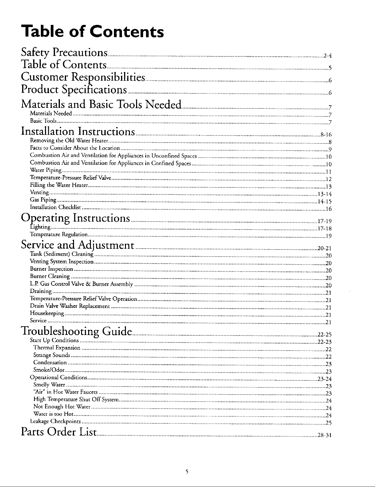
Table of Contents
<€,_,_,_,a,,._yPrecautions ............................................................................................................................................2-4
Table of Contents ................................................................................................................................................5
Customer
Product
lZesponslblhtles .......................................................................................................................6
bpecmcanons ..................................................................................................................................6
Materials and Basic Tools Needed ...............................................................................................7
Materials Needed ...................................................................................................................................................................... 7
BasicTools ................................................................................................................................................................................ 7
Installation Instructions ........................................................................................................................8-16
Removing the Old Water Heater ............................................................................................................................................... 8
Facts to Consider About the Location ....................................................................................................................................... 9
Combustion Air and Ventilation for Appliances in Unconfined Spaces ................................................................................... 10
Combustion Air and Ventilation for Appliances in Confined Spaces ....................................................................................... 10
Water Piping ........................................................................................................................................................................... 11
Temperature-Pressure Relief Valve........................................................................................................................................... 12
Filling the Water Heater .......................................................................................................................................................... 13
Venting .............................................................................................................................................................................. 13-14
Gas Piping ......................................................................................................................................................................... 14-15
Installation Checklist .............................................................................................................................................................. 16
"""Operating Instructions .........................................................................................................................17-19
Eight ng .7.. ...................................................................................................... 17-18
Temperature Regulation.......................................................................................................................................................... 19
Service and
Tank (Sediment) Cleaning--...................................................................................................................................................... 20
Venting System Inspection ...................................................................................................................................................... 20
Burner Inspection ................................................................................................................................................................... 20
Burner Cleaning ..................................................................................................................................................................... 20
L.P. Gas Control Valve & Burner Assembly ............................................................................................................................ 20
Draining ................................................................................................................................................................................. 21
Temperature-Pressure Relief Valve Operation .......................................................................................................................... 21
Drain Valve Washer Replacement ........................................................................................................................................... 21
Housekeeping ......................................................................................................................................................................... 21
Service .................................................................................................................................................................................... 21
Adlustment ......................................................................................................................20-21
_'_ "" -"lroubleshootmg Guide ........................................................................................................................22-25
Start Up Conditions .......................................................................................................................................................... 22-23
Thermal Expansion .............................................................................................................................................................. 22
Strange Sounds ..................................................................................................................................................................... 22
Condensation ....................................................................................................................................................................... 23
Smoke/Odor ......................................................................................................................................................................... 23
Operational Conditions ..................................................................................................................................................... 23-24
Smelly Water ........................................................................................................................................................................ 23
"Air" in Hot Water Faucets .......................................... i........................................................................................................ 23
High Temperature Shut OffSysrem ...................................................................................................................................... 24
Not Enough Hot Water ........................................................................................................................................................ 24
Water is too Hot ................................................................................................................................................................... 24
Leakage Checkpoints .............................................................................................................................................................. 25
Parts Order List...............................................................................................................................................28-3,
Customer Responsibilities
Thank You for purchasinga Sears water heater
Properly installed and maintained, it should give you years of
trouble free service. If you should decide that you want the new
water heater professionally installed by Sears call the local Sears
Service Center or any Sears store. They will arrange for prompt,
quality installation by Sears authorized contractors.
Abbreviations Found In This Instruction Manual
C.S.A. - Canadian Standards Association ,
A.N.S.I. - American National Standards Institute
N.EEA. - National Fire Protection Association
AWARNING
This gas-fired water heater is design certified by CSA
INTERNATIONAL under American National
StandardlCSA Standard for Gas Water Heaters ANS
Z21.10.1 • CSA 4.1 (latest edition). The installation must
conform with this manual, Local Codes and with the latest
edition of the National Fuel Gas Code, ANSI Z223.1.
This publication is available from your local government or
public library, gas company, or by writing NFPA,
Batterymarch Park, Quincy, MA 02269.
• Read the "Safety Precautions" section, pages 2 through 4 of
this manual first and then the entire manual carefully. If you
don't follow the safety rules, the water beater will not operate
properly. It could cause DEATH, SERIOUS BODILY
INJURY AND/OR PROPERTY DAMAGE.
This manual contains instructions for the installation, opera-
tion, and maintenance of the gas-fired water heater. It also
contains warnings through out the manual that you must read
and be aware of. All warnings and all instructions are essential
to the proper operation of the water beater and your safety.
Since we cannot put everything on the first few pages, READ
THE ENTIRE MANUAL BEFORE ATTEMPTING TO
INSTALL OR OPERATE THE WATER HEATER.
The installation must conform with the instructions in this
manual; gas company rules; and Local Codes, or in the
absence of Local Codes, with the latest edition of the National
Fuel Gas code, ANSI Z223.1, also referred to as NFPA 54
This publication is available from your local government or
public library or gas company or by writing NFPA,
Barterymarch Park, Quincy, MA 02269.
If after reading this manual you have any questions or do not
understand any portion of the instructions, call the Sears
Service Center.
Carefully plan the place where you are going to put the water
bearer. Correct combustion, vent action, and vent pipe instal-
lation are very important in preventing death from possible
carbon monoxide poisoning and fires.
Examine the location to ensure the water heater complies with
the "Facts to Consider About the Location" section in this
manual.
For California installation this water heater must be braced,
anchored, or strapped to avoid falling or moving during an
earthquake. See instructions for correct instaI[ation proce-
dures. Instructions may be obtained from your local dealer,
wholesaler, public utilities or California Office of the State
Architect, 400 P Street, Sacramento, CA 95814.
Complies with SCAQMD rule #1121 and districts having
equivalent NOx requirements.
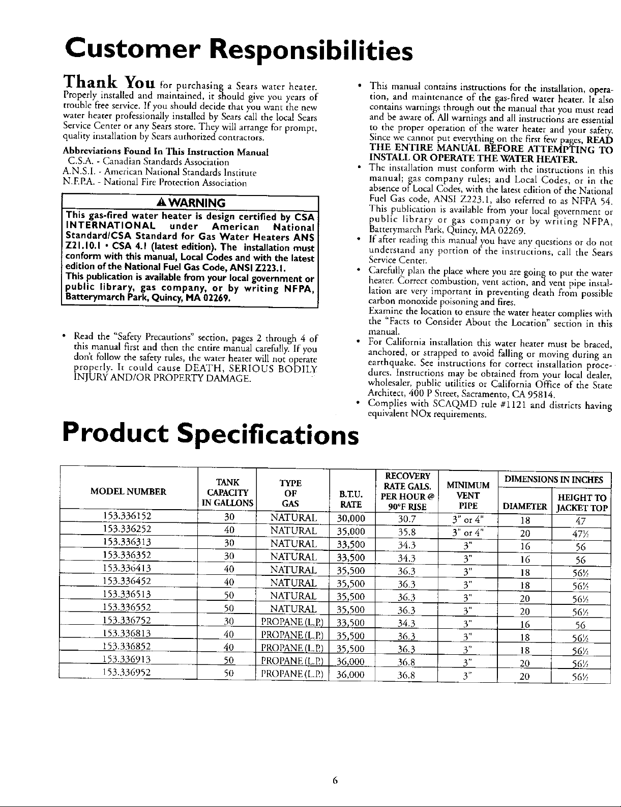
Product Specifications
MODEL NUMBER
153.336152
153.336252
153.336313
153.336352
153.336413
153.336452
153.336513
153.336552
153.336752
153.336813
153.336852
153.336913
153.336952
TANK
CAPACITY
IN GALLONS
30
40
30
30
40
40
50
50
30
40
40
50
50
TYPE
OF
GAS
NATURAL
NATURAL
NATURAL
NATURAL
NATURAL
NATURAL
NATURAL
NATURAL
PROPANE (L.E)
PROPANE (L.E)
PROPANE (L.E)
PROPANE (L.E)
PROPANE (L.P,)
B.ZU.
RATE
30,000
35,000
33,500
33,500
35,500
35,500
35,500
35,500
33,500
35,500
35,500
36_000
36,000
RECOVERY
RATEGALS.
PERHOUR @
90°F RISE
30.7
35.8
34.3
34.3
36.3
36.3
36.3
36.3
34.3
36.3
36.3
36.8
36.8
MINIMUM
VENT
PIPE
3" or4"
3" or 4"
3"
3"
3"
3"
3"
3"
3"
3"
3"
3"
3"
DIMENSIONS IN INcHEs
HEIGHT TO
DIAMETER JACKETTOP
18 47
20 47_
16 56
16 56
18 56_
18 56_
20 56½
20 56_
16 56
18 56_
18 56_
20 56_
20 56%
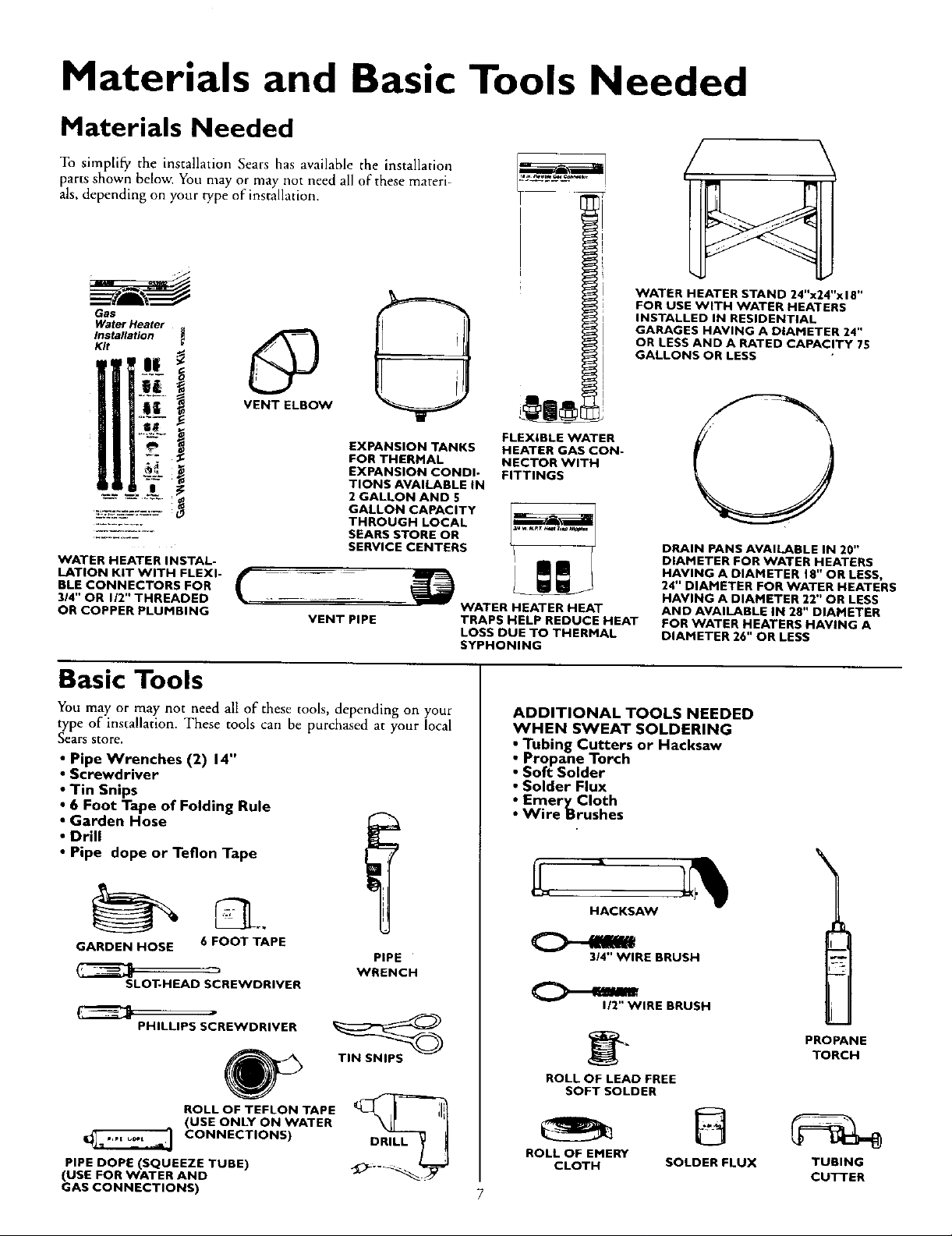
Materials and Basic Tools Needed
Materials Needed
To simplify the installation Sears has available the installation
parts shown below. You may or may not need all of these materi-
als, depending on your type of installation.
WATER HEATER STAND 24"x24"x I 8"
FOR USE WITH WATER HEATERS
Gas
Water Heater
Installation
Kit
INSTALLED IN RESIDENTIAL
GARAGES HAVING A DIAMETER 24"
OR LESS AND A RATED CAPACITY 75
GALLONS OR LESS
@
VENT ELBOW
EXPANSION TANKS
FOR THERMAL
EXPANSION CONDI-
TIONS AVAILABLE IN
2 GALLON AND 5
GALLON CAPACITY
THROUGH LOCAL
SEARS STORE OR
SERVICE CENTERS
WATER HEATER INSTAL-
LATION KIT WITH FLEXI-
BLE CONNECTORS FOR
314" OR 1/2" THREADED
OR COPPER PLUMBING
_ WATER HEATER HEAT
Basic Tools
You may or may not need all of these tools, depending on your
type of installation. These tools can be purchased at your local
Sears store.
• Pipe Wrenches (2) 14"
• Screwdriver
• Tin Snips
• 6 Foot Tape of Folding Rule
• Garden Hose
• Drill
• Pipe dope or Teflon Tape
FLEXIBLE WATER
HEATER GAS CON-
NECTOR WITH
FITTINGS
TRAPS HELP REDUCE HEAT
LOSS DUE TO THERMAL
SYPHONING
ADDITIONAL TOOLS NEEDED
WHEN SWEAT SOLDERING
• Tubing Cutters or Hacksaw
• Propane Torch
• Soft Solder
• Solder Flux
_ EmeryCIoth
Wire Brushes
DRAIN PANS AVAILABLE IN 20"
DIAMETER FOR WATER HEATERS
HAVING A DIAMETER 18" OR LESS,
24" DIAMETER FOR WATER HEATERS
HAVING A DIAMETER 22" OR LESS
AND AVAILABLE IN 28" DIAMETER
FOR WATER HEATERS HAVING A
DIAMETER 26" OR LESS
GARDEN HOSE 6 FOOT TAPE
SLOT-HEAD SCREWDRIVER
PHILLIPS SCREWDRIVER
ROLL OF TEFLON TAPE
(USE ONLY ON WATER
CONNECTIONS)
PIPE DOPE (SQUEEZE TUBE)
(USE FOR WATER AND
GAS CONNECTIONS)
PIPE
WRENCH
TIN SNIPS
DRILL
HACKSAW
3/4" WIRE BRUSH
1/2" WIRE BRUSH
PROPANE
TORCH
ROLL OF LEAD FREE
SOFT SOLDER
ROLL OF EMERY
CLOTH SOLDER FLUX TUBING
CUTTER
7
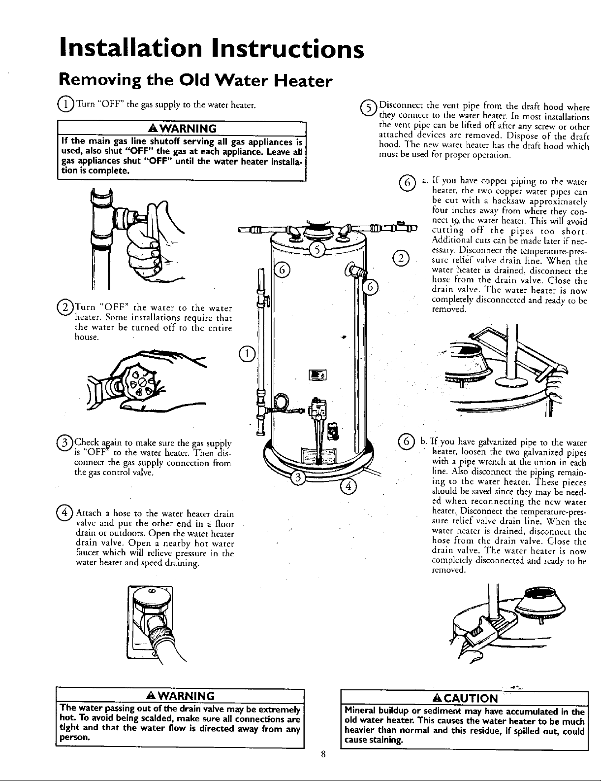
Installation Instructions
Removing the Old Water Heater
O Turn "OFF" the gas supply to the water heater.
AWARNING
If the main gas line shutoff serving all gas appliances is
used, also shut "OFF" the gas at each appliance. Leave all
gas appliances shut "OFF" until the water heater installa-
t on scomp ete.
QTurn "OFF" the water to the water
heater. Some installations require that
the water be turned off to the entire
house.
C
ODisconnect the vent pipe from the draft hood where
they connect to the water heater. In most installations
the vent pipe can be lifted off after any screw or other
attached devices are removed. Dispose of the draft
hood. The new water heater has the draft hood which
must be used for proper operation.
®
If you have copper piping to the water
heater, the two copper water pipes can
be cut with a hacksaw approximately
four inches away from where they con-
nect tg the water heater. This will avoid
curt[fig off the pipes too short.
Additional cuts c_in be made later if nec-
essary. Disconnect the temperature-pres-
sure relief valve drain line. When the
water heater is drained, disconnect the
hose from the drain valve. Close the
drain valve. The water heater is now
completely disconnected and ready to he
removed.
QCheck a,g,ain to make sure the gas supply
is OFF to the water heater. Then dis-
connect the gas supply connection from
the gas control valve.
Q Attach hose the heater drain
a to water
valve and put the other end in a floor
drain or outdoors. Open the water heater
drain valve. Open a nearby hot water
faucet which will relieve pressure in the
water heater and speed draining.
AWARNING t
The water passing out of the drain valve may be extremely I
hot. To avoid being scalded, make sure all connections are
tight and that the water flow is directed away from any
person.
you
b. If have galvanized pipe to the water
heater, loosen the two galvanized pipes
with a pipe wrench at the union in each
line. Also disconnect the piping remain-
ing to the water heater. These pieces
should be saved since they may be need-
ed when reconnecting the new water
heater. Disconnect the temperature-pres-
sure relief valve drain line. When the
water heater is drained, disconnect the
hose from the drain valve. Close the
drain valve. The water heater is now
completely disconnected and ready to be
re.loved,
ACAUTION I
Mineral buildup or sediment may have accumulated in the
old water heater. This causes the water heater to be much
heavier than normal and this residue, if spilled out, could
cause staining.
Installation Instructions (cont'd)
Facts to Consider About the
Location
You should carefully choose an indoor location for the new
water heater, because the placement is a very important consid-
eration for the safety of the occupants in the building and for
the most ecmiomical use of the appliance. This water heater is
not for use in mobile homes or outdoor installation.
Whether replacing an old water heater or putting the water
heater in a new location, the following critical points must be
observed.
• The location selected should be indoors as close as practical to
the gas vent or chimney to which the water heater vent is
going to be connected, and as centralized with the water pip-
ing system as possible. The water heater, as all water heaters,
will eventually leak. Do not install without adequate drainage
provisions where water flow will cause damage.
ACAUTION
WATER HEATERS EVENTUALLY LEAK:Installationofthe
water heatermust beaccomplishedin sucha manner that if
thetank or any connectionsshouldleak,theflowofwaterwill
not causedamageto the structure.Forthis reason,it isnot
advisableto installthe water heaterin an atticor upperfloor.
When suchlocationscannotbe avoided,a suitabledrain pan
shouldbe installedunderthe water heater. Drain pansare
availableat your localSearsstore.Sucha drain panmust be
not greaterthan 1¼inchesdeep,havea minimum lengthand
widthofat least2inchesgreaterthanthewater heaterdimen-
sionsandmust be pipedto an adequatedrain.The panmust
notrestrict combustionairflow.Underno circumstancesisthe
manufactureror Searsto be heldliablefor any waterdamage
inconnectionwiththis waterheater.
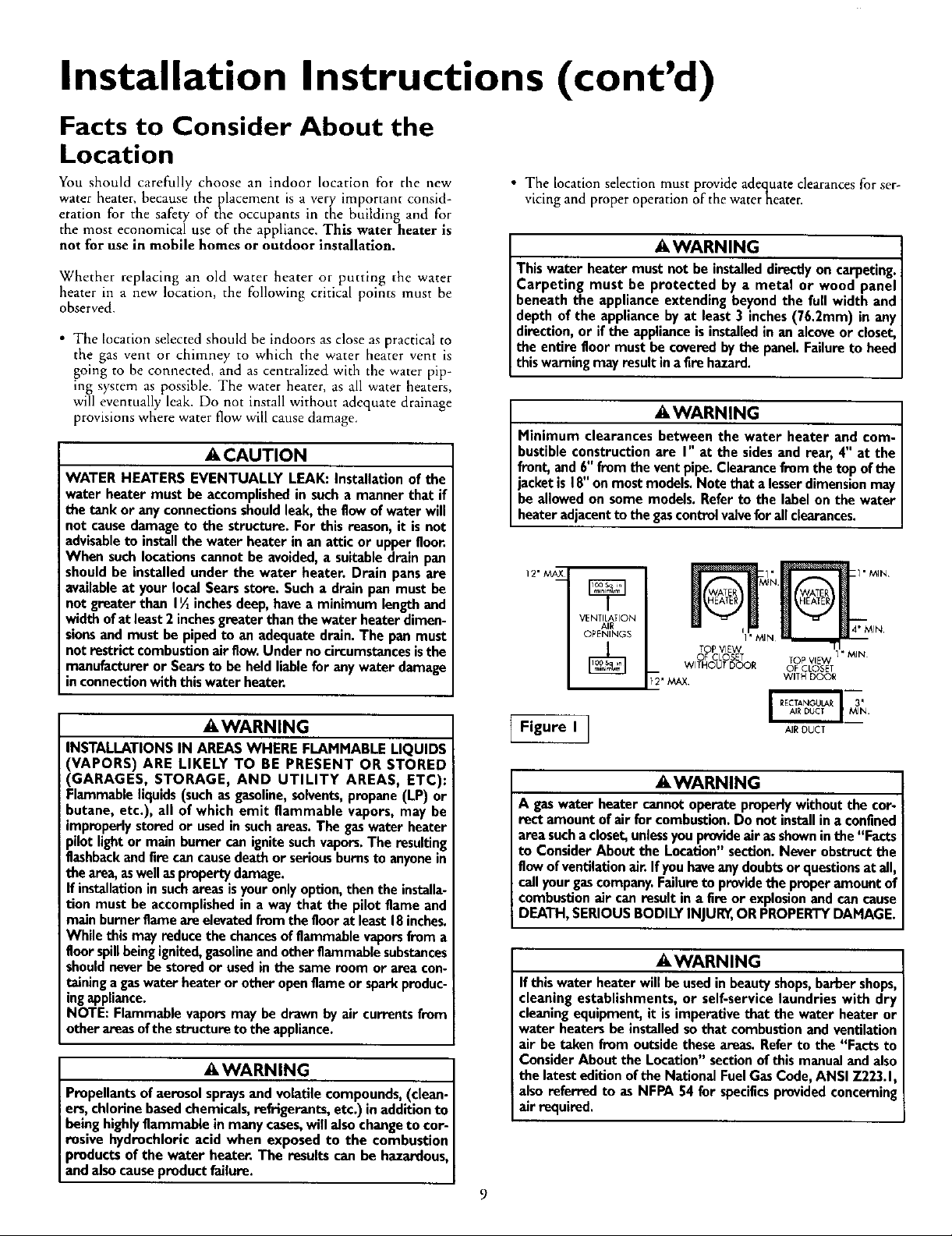
• The location selection must provide adec_uateclearances for ser-
vicing and proper operation of the waterneater.
AWARNING
Thiswater heater mustnot be installeddirectlyon carpeting.
Carpeting must be protected by a metal or wood panel
beneaththe applianceextendingbeyondthe full width and
depthof the appliance byat least3 inches(76.2mm) in any
direction,or ifthe applianceisinstalledin an alcoveor closet,
the entirefloor must be coveredbythe panel.Failureto heed
this warningmayresult inafirehazard.
AWARNING
Minimum clearancesbetween the water heater and com-
bustibleconstructionare I" at the sidesand rear, 4" at the
front,and 6"fromthe ventpipe.Clearancefromthe topofthe
jacketis 18"onmostmodels.Notethat alesserdimensionmay
beallowedon some models. Referto the labelonthe water
heateradjacentto the gascontrolvalveforallclearances.
12" _X
VENTILATION
AIR
OPENINGS
[_' MAX WITH DOOR
TOP VIEW _ I
OF CLOSET TOP VIEW
WITHOUT DOOR OF CLOSET
I'MIN
A WARNING
INSTALLATIONS IN AREAS WHERE FLAMMABLE LIQUIDS
(VAPORS) ARE LIKELY TO BE PRESENT OR STORED
(GARAGES, STORAGE, AND UTILITY AREAS, ETC):
Flammable liquids (such as gasoline, solvents,propane (LP) or
butane, etc.), all of which emit flammable vapors, may be
improperly stored or used in such areas. The gaswater heater
pilot light or main burner can ignite such vapors.The resulting
flashbackand fire can cause death or serious burnsto anyone in
the area, as well asproperty damage.
If installation in suchareas is your only option, then the installa-
tion must be accomplished in a way that the pilot flame and
main burner flame are elevated from the floor at least 18 inches.
While this may reduce the chancesof flammable vaporsfrom a
floor spillbeing ignited,gasolineand other flammable substances
should never be stored or used in the same room or area con-
taining a gaswater heater or other open flame or spark produc-
ingappliance.
NOTE: Flammable vapors may be drawn by air currents from
other areas of the structure to the appliance.
AWARNING
Propellants of aerosol spraysand volatile compounds, (clean-
ers, chlorine based chemicals, refrigerants, etc.) in addition to
being highly flammable in many cases,will also change to cor-
rosive hydrochloric acid when exposed to the combustion
products of the water heater. The results can be hazardous,
and also cause product failure.
Figure I_
AIR OUCT
A WARNING
A gaswater heater cannotoperateproperlywithoutthe cor-
rect amount ofair for combustion.Do not installina confined
areasuchacloset,unlessyouprovideair asshowninthe "Facts
to ConsiderAbout the Location"section.Neverobstructthe
flowofventilationair Ifyouhaveanydoubtsorquestionsatall,
callyour gascompany.Failuretoprovidethe properamount of
combustionair can result in a fire or explosionand cancause
DEATH,SERIOUSBODILYINJUR_,OR PROPERTYDAMAGE.
AWARNING
If this water heater will be usedin beauty shops,barber shops,
cleaning establishments, or self-service laundries with dry
cleaningequipment, it is imperative that the water heater or
water heaters be installed so that combustion and ventilation
air be taken from outside these areas. Refer to the "Facts to
Consider About the Location" section of this manual and also
the latest edition of the National FuelGas Code, ANSI Z223.1,
also referred to as NFPA 54 for specificsprovided concerning
air required.
9
Installation Instructions (cont'd)
Combustion Air and Ventilation
for Appliances Located in
Unconfined Spaces
Unconfined Space is a space whose volume is not less than 50
cubic feet per 1,000 Btu per hour of the aggregate input rating
of all appliances installed in that space. Rooms communicating
directly with the space in which the appliances are installed,
through openings not furnished with doors, are considered a
part of the unconfined space
In unconfined spaces in buildings, infiltration may be adequate
to provide air for combustion, ventilation and dilution of flue
gases. However, in buildings of tight construction (for example,
weather stripping, heavily insulated, caulked, vapor barrier, etc.),
additional air may need to be provided using the methods
described in Combustion Air and Ventilatiorl for Appliances
Located in Confined Spaces, b.
Combustion Air and Ventilation
for Appliances Located in
Confined Spaces
Confined Space is a space whose volume is less than 50 cubic
feet per 1,000 Btu per hour of the aggregateinput rating of all
appliances installed in that space.
a. ALL AIR FROM INSIDE BUILDINGSt
(See Page 8 Figure l, and Figure 2 below)
The confined space shall be provided with two permanent
openings communicating directly with an additional room(s)
of sufficient volume so that the combined volume of all
spaces meets the criteria for an unconfined space. The total
input of all gas utilization equipment installed in the com-
bined space shall be considered in making this determination.
Each opening shall have a minimum free area of one square
inch per 1,000 BTU per hour of the total input rating of all
gas utilization equipment in the confined space, but not less
than 100 square inches. One opening shall commence within
12 inches of the top and one commencing within 12 inches
of the bottom of the enclosure.
S VENT
--3
Figure 2 ]
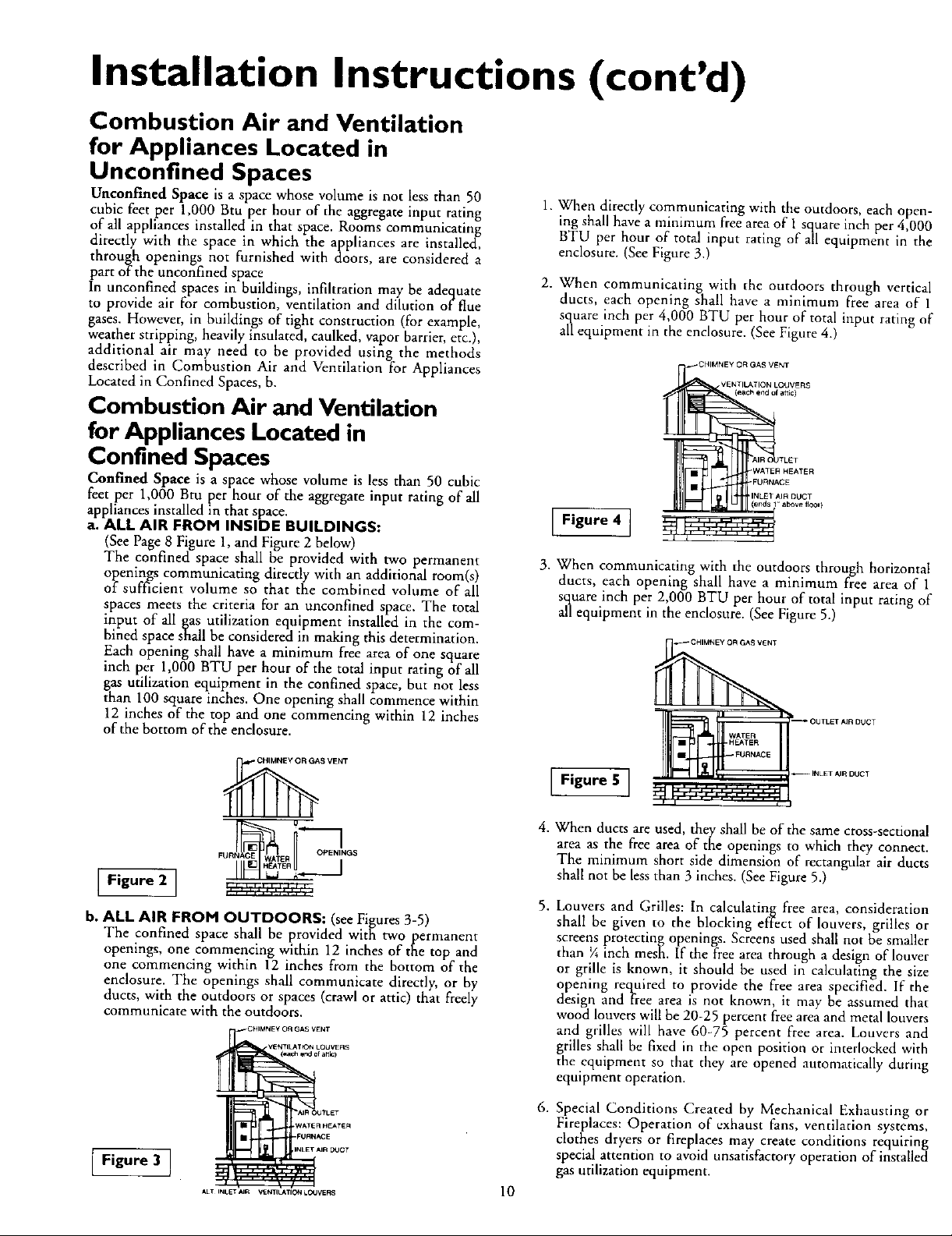
b. ALL AIR FROM OUTDOORS: (see Figures 3-5)
The confined space shall be provided with two permanent
openings, one commencing within 12 inches of the top and
one commencing within 12 inches from the bottom of the
enclosure. The openings shall communicate directly, or by
ducts, with the outdoors or spaces (crawl or attic) that freely
communicate with the outdoors.
II I_.J ,¢_.m.i_-,
CHIMNEy O_ GAS VENT
VE_TIt_T_ LOUVERS
(_ar_ end e{ attic)
1. When directly communicating with the outdoors, each open-
ing shall have a minimum free area of 1 square inch per 4,000
BTU per hour of total input rating of all equipment in the
enclosure. (See Figure 3.)
2. When communicating with the outdoors through vertical
ducts, each opening shall have a minimum free area of 1
square inch per 4,000 BTU per hour of total input rating of
all equipment in the enclosure. (See Figure 4.)
_CHIMNEY OR GAS VENT
Figure 4 ]
3. When communicating with the outdoors through horizontal
ducts, each opening shall have a minimum free area of 1
square inch per 2,000 BTU per hour of total input rating of
all equipment in the enclosure. (See Figure 5.)
_ CHIMNEY OR GAS VENT
Figure 5 ]
,
When ducts are used, they shall be of the same cross-sectional
area as the free area of the openings to which they connect.
The minimum short side dimension of rectangular air ducts
shall not be less than 3 inches. (See Figure 5.)
,
Louvers and Grilles: In calculating free area, consideration
shall be given to the blocking effect of louvers, grilles or
screens protecting openings. Screens used shall not be smaller
than ¼ inch mesh. If the free area through a design of louver
or grille is known, it should be used in calculating the size
opening required to provide the free area specified. If the
design and free area is not known, it may he assumed that
wood louvers will be 20-25 percent free area and metal louvers
and grilles will have 60-75 percent free area. Louvers and
grilles shall be fixed in the open position or interlocked with
the equipment so that they are opened automatically during
equipment operation.
VENTILATION LOUVERS
(each end of attic)
WATER HEATER
FURNACE
LET
INLET AIR DUCT
above tloor }
i_ OUTLET AJR DUCT
WATER
HEATER
FURNACE
-- INLET AIR DUCT
Figure 3 ]
AIR OUTLET
WATER HEATER
_IR DOCT
ALT INLETAIR VENTILATIONLO4JVERS
FURN,'_3E
6. Special Conditions Created by Mechanical Exhausting or
Fireplaces: Operation of exhaust fans, ventilation systems,
clothes dryers or fireplaces may create conditions requirin_
special attention to avoid unsatisfactory operation of insta[leci
gas utilization equipment.
10
 Loading...