

Kenmore 153.335963 User Manual
KGnmarG
Owners
Manual
FOR POTABLE WATER
HEATING ONLY
NOT SUITABLE FOR
SPACE HEATING
NOT FOR USE IN
MOBILE HOMES
Model No.
153.335816
153.335846
153.335863
153.335916
153.335943
153.335963
40 Gal.
40 Gal. High Altitude LP.
40 Gal. L.R
50 Gal.
50 Gal. High Altitude LP.
50 Gal. LP.
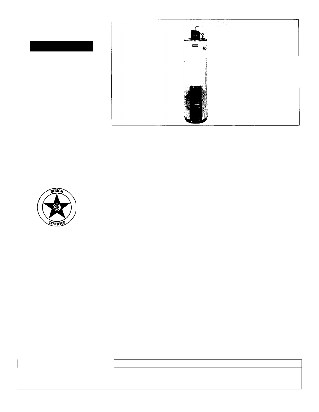
POWERMISER^«9
POWER VENT
GAS WATER HEATER
• Safety Instructions • Care and Maintenance
• Installation • Troubleshooting
• Operation • Parts List
For Your Safety
AN ODORANT IS ADDED TO THE GAS USED BY THIS
WATER HEATER
Read and Follow
All Safety Rules and
Operating Instructions
Before First Use of
This Product.
WARNING: If the information in these instructions are not fol
lowed exactly, a fire or explosion may result, causing property
damage, personal injury or death.
-Do not store or use easoline or other flammable vapors and liq
uids in the vicinity of this or any other appliance.
-WHAT TO DO IF YOU SMELL GAS
• Do not try to light any appliance.
• Do not touch any electrical switch; do not use any phone in your
building.
• Immediately call your ^as supplier from a neighbor’s phone.
Follow the gas supplier’s instructions.
• If you can not reacn your gas supplier, call the fire department.
-Installation and service must be performed by a qualified installer,
service agency or the gas supplier.
A WARNING
Improper installation, adjustment, alteration, service or maintenance
can cause DEATH, SERIOUS BODILY INJURY, OR PROPERTY DAM
AGE. Refer to this manual for assistance or consult the local Sears
Service Center or gas utility for further information.
AWARNING
Flammable vapors may be drawn by air currents from other areas
of the structure to this appliance.
__________________________
Save this Manual for Future Reference,
Sears, Roebuck and Co., Hoffman Estates, IL 60179 U.S.A.
AWARNING
READ THE GENERAL SAFETY SECTION BEGINNING ON INSIDE
COVER AND THEN THIS ENTIRE MANUAL BEFORE INSTALLING
OR OPERATING THIS WATER HEATER.

Safety Precautions
AWARNING
Improper installation, adjustment, alteration, service or
maintenance can cause death, serious bodily injury, or
property damage. Refer to this manual for assistance or
consult your local Sears Service Center for further
information.
AWARNING
WATER HEATERS EQUIPPED FOR ONE TYPE GAS
ONLY: This water heater is equipped for one type gas
only. Check the model rating plate near the gas control
valve for the correct gas. DO NOT USE THIS WATER
HEATER WITH ANY GAS OTHER THAN THE ONE
SHOWN ON THE MODEL RATING PLATE. Failure to
use the correct gas can cause problems which can result in
DEATH, SERIOUS BODILY INJURY, OR PROPERTY
DAMAGE. If you have any questions or doubts consult
your gas supplier or local utility.
AWARNING
INSTALLATIONS IN AREAS WHERE FLAMMABLE LIQ
UIDS {VAPORS) ARE LIKELY TO BE PRESENT OR
STORED (GARAGES, STORAGE, AND UTILITY AREAS,
ETC): Flammable liquids (such as gasoline, solvents,
propane (LP) or butane, etc.), all of which emit flammable
vapors, may be improperly stored or used in such areas.
The gas water heater pilot light or main burner can ignite
such vapors. The resulting flashback and fire can cause
death or serious burns to anyone in the area, as welt as
property damage.
If installation in such areas is your only option, then the
installation must be accomplished in a way that the pilot
flame and main burner flame are elevated from the floor
at least 18 inches. While this may reduce the chances of
flammable vapors from a floor spill being ignited, gasoline
and other flammable substances should never be stored or
used in the same room or area containing a gas water
heater or other open flame or spark producing appliance.
NOTE: Flammable vapors may be drawn by air currents
from other areas of the structure to the appliance.
AWARNING
If this water heater will be used in beauty shops, barber
shops, cleaning establishments, or self-service laundries
with dry cleaning equipment, it is imperative that the
water heater or water heaters be installed so that com
bustion and ventilation air be taken from outside these
areas. Refer to the ‘‘Locating The New Water Heater"
section of this manual and also the latest edition of the
National Fuel Gas Code, ANSI Z223.I, also referred to as
NFPA 54 for specifics provided concerning air required.
AWARNING
A fire can start if combustible materials such as clothing,
cleaning materials, or flammable liquids are placed against
or next to the water heater.
______________
__
AWARNING
At the time of manufacture this water heater was provid
ed with a combination temperature-pressures relief valve
certified by a nationally recognized testing laboratory
that maintains periodic inspection of production of listed
equipment or materials, as meeting the requirements
for Relief Valves and Automatic Gas Shutoff Devices for
Hot Water Supply Systems, and the latest edition of
ANSI Z2I.22 and the code requirements of ASME. If
replaced, the valve must meet the requirements of local
codes, but not less than a combination temperature and
pressure relief valve certified as meeting the require
ments for Relief Valves and Automatic Gas Shutoff
Devices for Hot Water Supply Systems, ANSI Z2I.22 by
a nationally recognized testing laboratory that maintains
periodic inspection of production of listed equipment or
materials.
The valve must be marked with a maximum set pressure
not to exceed the marked hydrostatic working pressure
of the water heater (ISO Ibs./sq. in.) and a discharge
capacity not less than the water heater input rate as
shown on the model rating plate. (Electric heaters watts divided by 1000 x 341S equal BTU/Hr. rate.)
Your local jurisdictional authority, while mandating the
use of a temperature-pressure relief valve complying
with ANSI Z2I.22 and ASME, may require a valve model
different from the one furnished with the water heater.
Compliance with such local requirements must be satis
fied by the installer or end user of the water heater with
a locally prescribed temperature-pressure relief valve
installed in the designated opening in the water heater in
place of the factory furnished valve.
For safe operation of the water heater, the relief valve
must not be removed from it’s designated opening or
plugged.
The temperature-pressure relief valve must be installed
directly into the fitting of the water heater designated
for the relief valve. Position the valve downward and pro
vide tubing so that any discharge will exit only within 6
inches above, or at any distance below the structural
floor. Be certain that no contact is made with any live
electrical part. The discharge opening must not be
blocked or reduced in size under any circumstances.
Excessive length, over 30 feet, or use of more than four
elbows can cause restriction and reduce the discharge
capacity of the valve. '
No valve or other obstruction is to be placed between
the relief valve and the tank. Do not connect tubing
directly to discharge drain unless a 6" air gap is provided.
To prevent bodily injury, hazard to life, or property dam
age, the relief valve must be allowed to discharge water
in quantities should circumstances demand. If the dis
charge pipe is not connected to a drain or other suitable
means, the water flow may cause property damage.
The Discharge Pipe:
• Must not be smaller in size than the outlet pipe size of
the valve, or have any reducing couplings or other
restrictions.
• Must not be plugged or blocked.
• Must be of material listed for hot water distribution.
• Must be installed so as to allow complete drainage of
both the temperature-pressure relief valve, and the
discharge pipe.
• Must terminate at an adequate drain.
• Must not have any valve between the relief valve and
tank.

Safety Precautions
AWARNING
A gas water heater cannot operate properly without the
correct amount of air for combustion. Do not install in a
confined area such a closet, unless you provide air as
shown in the “Locating The New Water Heater” section.
Never obstruct the flow of ventilation air. If you have any
doubts or questions at all, call your gas company. Failure
to provide the proper amount of combustion air can result
in a fire or explosion and can cause DEATH, SERIOUS
BODILY INJURY, OR PROPERTY DAMAGE.
A WARNING
HOTTER WATER CAN SCALD: Water heaters are
intended to produce hot water. Water heated to a tem
perature which will satisfy clothes washing, dish washing,
and other sanitizing needs can scald and permanently
injure you upon contact. Some people are more likely to
be permanently injured by hot water than others. These
include the elderly, children, the infirm, or physically/mentally handicapped. If anyone using hot water in your home
fits into one of these groups %r if there is a local code or
state law requiring a certain temperature water at the hot
water tap, then you must take special precautions. In addi
tion to using the lowest possible temperature setting that
satisfies your hot water needs, a means such as a mixing
valve, should be used at the hot water taps used by these
people or at the water heater. Mixing valves are available
at plumbing supply or hardware stores. Follow manufac
turers instructions for installation of the valves. Before
changing the factory setting on the thermostat, read the
“Temperature Regulation” section in this manual.
AWARNING
This water heater must not be installed directly on car
peting. Carpeting must be protected by a metal or wood
panel beneath the appliance extending beyond the full
width and depth of the appliance by at least 3 inches
(76.2mm) in any direction, or if the appliance is installed
in an alcove or closet, the entire floor must be covered by
the panel. Failure to heed this warning may result In a
fire hazard.
AWARNING
The power vent water heater requires its own (separate)
venting system. It cannot be connected to an existing vent
pipe or chimney. It must be terminated to the outdoors.
Failure to properly install the venting system can result in
asphyxiation, a fire or explosion and can cause DEATH, SE
RIOUS BODILY INJURY, OR PROPERTY DAMAGE.
AWARNING
No vent damper installation is compatible with this power
vented water heater design. No vent damper, whether it is
operated thermally or otherwise is to be installed on this
power vented water heater. Alteration of any part of the fac
tory-furnished vent assembly could result in improper oper
ation due to restriction of flue gases, spillage of flue gases
and may cause carbon monoxide poisoning.
AWARNING
Soot build-up indicates a problem that requires correc
tion before further use. Turn “off” gas to water heater
and leave “off” until repairs are made, because failure to
correct the cause of the sooting can result in a fire or
explosion causing DEATH, SERIOUS BODILY INJURY,
OR PROPERTY DAMAGE.
AWARNING
BEFORE LIGHTING [PROPANE (L.P.) GAS WATER
HEATERS]: Propane (L.P.) gas is heavier than air. Should
there be a leak in the system, the gas will settle near the
ground. Basements, crawl spaces, skirted areas under
mobile homes (even when ventilated), closets and areas
below ground level will serve as pockets for the accumula
tion of this gas. Before attempting to light or relight the
water heater’s pilot or turning on a nea^y electrical light
switch, be absolutely sure there is no accumulated gas in
the area. Search for odor of gas by sniffing at ground level
in the vicinity of the appliance. If odor is detected, follow
steps indicated at “For Your Safety” on the cover page of
this manual then leave the premises.
AWARNING
• The appliance and its individual shutoff valve must be dis
connected from the gas supply piping system during any
pressure testing of the gas system at test pressures in
excess of 1/2 pound per square inch (3.5kPa).
• The appliance must be isolated from the gas supply pip
ing system by closing its individual manual shutoff v^ve
during any pressure testing of the gas supply piping sys
tem at test pressures equal or less than 1/2 pound per
square inch (3.5kPa). '
AWARNING
Chemical vapor corrosion of the flue and vent system
may occur if air for combustion contains certain chemical
vapors. Spray can propellants, cleaning solvents, refrigera
tor and air conditioner refrigerants, swimming pool
chemicals, calcium and sodium chloride, waxes, bleach,
and process chemicals are typical compounds which are
potentially corrosive.
AWARNING
Obstructed or deteriorated vent systems may present a
serious health risk or asphyxiation.
Safety Precautions continued on page 4.

Safety
AWARNiNG
The water heater with draft hood installed must be prop
erly vented to a chimney which terminates outdoors.
Never operate the water heater unless it is vented to the
outdoors and has adequate air supply to avoid risks of
improper operation, explosion or asphyxiation.
AWARNING
Minimum clearances between the water heater and com
bustible construction are 0" at the sides and rear, 5" at the
front, and 0" from the vent pipe. Clearance from the top
of the jacket is 14" on most models. Note that a lesser
dimension may be allowed on some models. Refer to the
label on the water heater adjacent to the gas control valve
for all clearances.
AWARNING
Do not use this appliance if any part of it has been under
water. Immediately calKa Sears Service Technician to
inspect the appliance and to replace the gas control or any
part of the burner system which has been under water.
^
______________
Vent termination must not be within 4 feet of any items
such as gas meters, gas valves or other gas regulating
equipment.
__________________
AWARNING
_________________
A CAUTION
WATER HEATERS EVENTUALLY LEAK: Installation of
the water heater must be accomplished in such a manner
that if the tank or any connections should leak, the flow of
water will not cause damage to the structure. For this
reason, it is not advisable to install the water heater in an
attic or upper floor. When such locations cannot be avoid
ed, a suitable drain pan should be installed under the
water heater. Drain pans are available at your local Sears
store. Such a drain pan must be not greater than I '/: inch
es deep, have a minimum length and width of at least 2
inches greater than the water heater dimensions and
must be piped to an adequate drain. The pan must not
restrict combustion air flow. Under no circumstances is
the manufacturer or Sears to be held liable for any water
damage in connection with this water heater.
^
AWARNING
HYDROGEN GAS: Hydrogen gas can be produced in a hot
water system that has not been used for a long period of
time (generally two weeks or more). Hydrogen gas is
extremely flammable and explosive. To prevent the possi
bility of injury under these conditions, we recommend the
hot water faucet be opened for several minutes at the
kitchen sink before any electrical appliances which are
connected to the hot water system are used (such as a
dishwasher or washing machine). If hydrogen gas is pre
sent, there will probably be an unusual sound similar to air
escaping through the pipe as the hot water faucet is
opened. There must be no smoking or open flame near
the faucet at the time it is open.
AWARNING
INSULATING JACKETS: When installing an external
water heater insulation jacket on a gas water heater:
• DO NOT cover the temperature-pressure relief valve.
• DO NOT put insulation over any part of the top of the
gas water heater.
• DO NOT put insulation over the gas control valve or gas
control valve/burner cover, or any access areas to the
burner.
• DO NOT let insulation around the gas water heater to
get within 8 inches of the floor (air must get to the
burner).
• DO NOT cover or remove operating instructions, and
safety related warning labels and materials affixed to the
water heater.
Failure to heed this will result in the possibility of a fire or
explosion.

Table of Contents
Safety Precautions...................................................................................2-4
Table of Contents......................................................................................5
Customer Responsibilities
.......................................................................
Product Specifications..............................................................................6
Materials and Basic Tools Needed
Materials Needed....................................................................................................................................................................................................................................................7
Basic Tools............................................................................................................................................................................................................................................................ 7
..........................................................
Installation Instructions........................................................................8-23
Removing rhe Old Water Heater
Locating the New Water Heater........................................................................................................................................................................................................................g.jO
Combustion Air and Ventilation..........................................................................................................................................................................................................................[ j
Venting Clearances......................................................................................................................................................................................................................................... 11
Combustion Air and Ventilation for Appliances in Unconfined Spaces........................................................................................................................................................12
Combustion Air and Ventilation for Appliances in Confined Spaces............................................................................................................................................................ 12
Water Piping..........................................................................................................................................................................................................................................................13
TemperaturC'Pressure Relief Valve................................................................................................................................................................................................................. 14
Filling the Water Heater.......................................................................................................................................................................................................................................15
Wiring............................................................................................................................................................................................................................................................. 15-16
Venting..............................................................................................................................................................................................................................................................16-21
Gas Piping...............................................................................................................................................................................................................................................................22
Installation Checklist............................................................................................................................................................................................................................................. 23
........................................................................................................................................................................................................................8
Operating Instructions.........................................................................24-27
Lighting............................................................................................................................................................................................................................................................. 25-26
Temperature Regulation...................................................................................................................................................................................................................................... 27
6
7
Service and Adjustment.......................................................................28-30
Tank (Sediment) Cleaning.....................................................................................................................................................................................................................................28
Venting System Inspection................................................................................................................................................................................................................................. 28
Oiling Instructions
Burner Inspection
Burner Cleaning................................................................................................................................................................................................................................................... 28
L.P. Gas Control Valve & Burner Assembly Replacement Information.........................................................................................................................................................29
Draining................................................................................................................................................................................................................................................................ 29
Temperature-Pressure Relief Valve Operation...................................................................................................................................................................................................29
Drain Valve Washer Replacement....................................................................................................................................................................................................................... 30
Housekeeping....................................................................................................................................................................................................................................................... 30
Service.....................................................................................................................................................................................................................................................................30
.............................................................................................................................................................................................................................................. 28
................................................................................................................................................................................................................................................ 28
Troubleshooting Guide.........................................................................31-38
Start Up Conditions................................................................................................................................................................................................................................................. 31
Thermal Expansion................................................................................................................................................................................................................................................31
Strange Sounds..................................................................................................................................................................................................................................................... 31
Condensation.......................................................................................................................................................................................................................................................... 32
Smoke/Odor............................................................................................................................................................................................................................................................32
Operational Conditions.......................................................................................................................................................................................................................................32-33
Smelly Water........................................................................................................................................................................................................................................................ 32
“Air” in Hot Water Faucets................................................................................................................................................................................................................................ 33
Venting Manual Reset Switch............................................................................................................................................................................................................................33
High Temperature Shut off System..................................................................................................................................................................................................................... 33
Not Enough or No Hot Water...............................................................................................................................................................................................................................33
Water Is Too Hot....................................................................................................................................................................................................................................................33
Leakage Checkpoints................................................................................................................................................................................................................................................34
Thermostat and Gas Supply Check.........................................................................................................................................................................................................................35
Electrical System Check.....................................................................................................................................................................................................................................36-38
Parts Order List............................................................................................................................................................................................................. 40-43
5

Customer Responsibilities
Thank You for purchasing a Sears water heater. Properly
installed and maintained, it should give you years of trouble free ser
vice. If you should decide that you want the new water heater profes
sionally installed by Sears call the local Sears Service Center or any
Sears store. They will arrange for prompt, quality' installation by Sears
authorized contractors.
Abbreviations Found In This Instruction Manual
CSA - Canadian Standards Association
ANSI - American National Standards Institute
NFPA - National Fire Protection Association
A WARNING
This gas-fired water heater is design certified by CSA
INTERNATIONAL under American National
Standard/CSA Standard for Gas Water Heaters ANS
Z21.10.1 ■ CSA 4.1 (latest edition). The installation must
conform with this manual, Local Codes and with the latest
edition of the National Fuel Gas Code, ANSI Z223.1.
This publication is available from your local government or
public library, gas company, or by writing NFPA,
Batterymarch Park, Quincy, MA 02269.
Read the “Safety Precautions” section, pages 2 and 3 of this
manual first and then the entire manual carefully. If you don’t
follow the safety rules, the water heater will not operate prop
erly. It could cause DEATH, SERIOUS BODILY INJURY
AND/OR PROPERTY DAMAGE.
This manual contains instructions for the installation, opera
tion, and maintenance of the gas-fired water heater. It also
contains warnings through out the manual that you must read
and be aware of. All warnings and alt instructions are essential
to the proper operation of the water heater and your safety.
Since we cannot put everything on the first few pages, READ
THE ENTIRE MANUAL BEFORE ATTEMPTING TO
INSTALL OR OPERATE THE WATER HEATER.
The installation must conform with the instructions in this
manual; gas company rules; and Local Codes, or in the
absence of Local Codes, with the latest edition of the National
Fuel Gas code, ANSI Z223.1, also referred to as NFPA 54.
This publication is available from your local government or
public library or gas company or by writing NFPA,
Batterymarch Park, Quincy, MA 02269.
If after reading this manual you have any questions or do not
understand any portion of the instructions, call the Sears
Service Center.
Carefully plan the place where you are going to put the water
heater. Correct combustion, vent action, and vent pipe instal
lation are very important in preventing death from possible
carbon monoxide poisoning and fires.
Examine the location to ensure the water heater complies with
the “Locating the New Water Heater” section in this manual.
For California installation this water heater must be braced,
anchored, or strapped to avoid falling or moving during an
earthquake. See instructions for correct installation proce
dures. Instructions may be obtained from your local dealer,
wholesaler, public utilities or California Office of the State
Architect, 400 P Street, Sacramento, CA 95814,
Complies with SCAQMD rule #1121 and districts having
equivalent NOx requirements.
Product Specifications
MODELNUMBER
CAPACITY
IN GALLONS
TANK
153.335816
153.335846
153.335863 40 PROPANE
153.335916 50
153.335943 50 PROPANE
153.335963
40 NATURAL
40 PROPANE
50
‘ Limited usage of 2" vent pipe - see pages 16 and 19.
TYPE
OF
GAS
NATURAL
PROPANE
B.T.U.
RATE
40,000
40,000
40,000
40,000
40,000
40,000
RECOVERY
RATE GALS.
PER HOUR
@ 90°F RISE
40.9 3" 18" 60"
40.9 3” 18" 60"
40.9
40.9
40.9 3" 20"
40.9
MINIMUM
’VENT
PIPE*
3" ’ 18" 60"
3" 20"
3" 20"
DIMENSIONS IN INCHES
DIAMETER
HEIGHT TO
JACKET TOP
5914"
5914"
59Z"
Materials and Basic Tools Needed
Materials Needed
To simplify the installation Sears has available the installation
parts shown below. You may or may not need all of these materi
als, depending on your type of installation.
WATER HEATER STAND 24"xI4"xl8"
Gas
Water Heater
Installation
Kit
II
M
,ii.
T
EXPANSION TANKS FOR
THERMAL EXPANSION
CONDITIONS AVAILABLE IN
2 GALLON AND 5 GALLON
CAPACITY THROUGH
Í
i
I
?
%
Ú
LOCAL SEARS STORE OR
SERVICE CENTERS
FLEXIBLE WATER HEATER
GAS CONNECTOR WITH
FITTINGS
r>. T. Heal Trsp WrM*«
FOR USE WITH WATER HEATERS
INSTALLED IN RESIDENTIAL
GARAGES HAVING A DIAMETER 24"
OR LESS AND A RATED CAPACITY 75
GALLONS OR LESS
WATER HEATER
INSTALLATION KIT WITH
FLEXIBLE CONNECTORS
FOR 3/4" OR 111" THREAD
ED OR COPPER PLUMBING
PVC VENT ELBOW
I)
PVC VENT EXTENSION
Basic Tools
You may or may not need all of these cools, depending on your
type of installation. These tools can be purchased at your local
Sears store.
• Pipe Wrenches (2) 14"
• Screwdriver
• Tin Snips
> 6 Foot Tape of Folding Rule
• Garden Hose
• Drill
• Pipe dope or Teflon Tape
GARDEN HOSE
SLOT-HEAD SCREWDRIVER
PHILLIPS SCREWDRIVER
PIPE DOPE (SQUEEZE TUBE)
(USE FOR WATER AND
GAS CONNECTIONS)
6 FOOT TAPE
ROLL OF TEFLON TAPE
(USE ONLY ON WATER
CONNECTIONS)
PIPE
WRENCH
TIN SNIPS
WATER HEATER HEAT
TRAPS HELP REDUCE HEAT
LOSS DUE TO THERMAL
SYPHONING
ADDITIONAL TOOLS NEEDED
WHEN SWEAT SOLDERING
• Tubing Cutters or Hacksaw
• Propane Torch
• Soft Solder
• Solder Flux
• Emery Cloth
• Wire Brushes
HACKSAW
3/4" WIRE BRUSH
ROLL OF LEAD FREE
SOFT SOLDER
ROLL OF EMERY
CLOTH
DRAIN PANS
AVAILABLE IN 20" DIAMETER FOR
WATER HEATERS HAVING A DIAME
TER 18" OR LESS. 24" DIAMETER FOR
WATER HEATERS HAVING A DIAME
TER 22" OR LESS AND AVAILABLE IN
28" DIAMETER FOR WATER HEATERS
HAVING A DIAMETER 26" OR LESS
\
' WIRE BRUSH
PROPANE
TORCH
SOLDER FLUX
TUBING
CUTTER
ñ
Installation Instructions
Removing the Old Water Heater
© Turn “OFF” the gas supply to the water heater.
AWARNING
If the main gas line shutoff serving aii gas appiiances is
used, aiso shut “off" the gas at each appiiance. Leave aii
gas appliances shut “off” until the water heater installation
is compiete.
^^Turn “OFF” the wa^r to the water
heater. Some installations require that
the water be turned off to the entire
house.
Disconnect the vent pipe from the draft hood where
they connect to the water heater. In most installations
©
the vent pipe can be lifted off after any screw or other
attached devices are removed. Dispose of the draft
hood. The new water heater has the draft hood which
must be used for proper operation,
a. If you have copper piping to the water
©
heater, the two copper water pipes can
be cut with a hacksaw approximately
four inches away from where they con
nect to the water heater. This will avoid
cutting off the pipes too short.
Additional cuts can be made later if nec
essary. Disconnect the temperature-pres
sure relief valve drain line. When the
water heater is drained, disconnect the
hose from the drain valve. Close the
drain valve. The water heater is now
completely disconnected and ready to be
removed.
Check again to make sure the gas supply
is “OFF ’ to the water heater. Then dis
connect the gas supply connection from
the gas control valve.
Attach a hose to the water heater drain
valve and put the other end in a floor
drain or outdoors. Open the water heater
drain valve. Open a nearby hot water
faucet which will relieve pressure in the
water heater and speed draining.
AWARNING
The water passing out of the drain valve may be extremely
hot. To avoid being scalded, make sure all connections are
tight and that the water flow is directed away from any
person.
b. If you have galvanized pipe to the water
heater, loosen the two galvanized pipes
with a pipe wrench at the union in each
line. Also disconnect the piping remain
ing to the water heater. These pieces
should be saved since they may be need
ed when reconnecting the new water
heater. Disconnect the temperature-pres
sure relief valve drain line. When the
water heater is drained, disconnect the
hose from the drain valve. Close the
drain valve. The water heater is now
completely disconnected and ready to be
removed.
ACAUTION
Mineral buildup or sediment may have accumulated in the
old water heater. This causes the water heater to be much
heavier than normal and this residue, if spilled out, could
cause staining.
Installation Instructions
Locating the New Water Heater
You should carefully choose an indoor location for the new water
heater, because the placement is a very important consideration
tor the safety of the occupants in the building and for the most
economical use of the appliance. This water heater is not for
use in mobile homes or outdoor installation.
Whether replacing an old water heater or putting the water
heater in a new location, the following critical points must be
observed.
1. The location selected should be indoors as close as practical
to the vent termination point, and as centralized with the
water piping system as possible. The water heater, as all water
heaters, will eventually leak. Do not install without adequate
drainage provisions where water flow will cause damage.
2. If vented through an outside wall or through the roof the
vent piping cannot exceed a total of 35 feet including vertical
and horizontal runs and have no more than 3 elbows. It can
not slope downward and horizontal runs require '/t" per foot
rise. All horizontal runs require adequate support at feet
intervals.
3. The water heater requires ifc own (separate) venting system.
It cannot be connected to an existing vent pipe or chimney.
It must terminate to the outdoors. Whenever possible termi
nate the vent on the leaward side of the building if vented
through an outside wall.
ated, at times, as the combustion gases exit the vent cap
and discoloration of surfaces in proximity to the vent cap
may occur.
The power vent water heater requires its own (separate) venting
system. It cannot be connected to an existing vent pipe or chim
ney. It must be terminated to the outdoors. Failure to properly in
stall the venting system can result in asphyxiation, a fire or explo
sion and can cause DEATH. SERIOUS BODILY INJURY, OR
PROPERTY DAMAGE.
4. The water heater comes equipped with a 5 foot power cord
which can be used to connect to a 110/120 volt power
source if (1) local codes allow, and (2) there is a three prong
receptacle available.
NOTE: Condensation may be cre
AWARNING
5. The location selection must provide adequate clearances for
servicing and proper operation of the water heater.
AWARNING
INSTALLATIONS IN AREAS WHERE FLAMMABLE LIQUIDS
(VAPORS) ARE LIKELY TO BE PRESENT OR STORED
(GARAGES, STORAGE, AND UTILITY AREAS, ETC):
Flammable liquids (such as gasoline, solvents, propane (LP) or
butane, etc.), all of which emit flammable vapors, may be
improperly stored or used in such areas. The gas water heater
pilot light or main burner can Ignite such vapors. The resulting
flashback and fire can cause death or serious bums to anyone in
the area, as well as property damage.
tf installation in such areas is your only option, then the installa
tion must be accomplished in a way that the pilot flame and
main burner flame are elevated from the floor at least 18 inches.
While this may reduce the chances of flammable vapors from a
floor spill being ignited, gasoline and other flammable substances
should never be stored or used in the same roorn or area con
taining a gas water heater or other open flame or spark produc
ing appliance.
NOTE: Flammable vapors may be drawn by air currents from
other areas of the structure to the appliance.
AWARNING
Propellants of aerosol sprays and volatile compounds, (clean
ers, chlorine based chemicals, refrigerants, etc.) in addition to
being highly flammable in many cases, will also change to cor
rosive hydrochloric add when exposed to the combustion
products of the water heater. The results can be hazardous,
and also cause product l^lure.
AWARNING
This water heater must not be installed directly on carpeting.
Carpeting must be protected by a metal or wood panel
beneath the appliance extending beyond the full width and
depth of the appliance by at least 3 inches (76.2mm) in any
direction, or if the appliance is installed in an alcove or closet,
the entire floor must be covered by the panel. Failure to heed
this warning may result in a fire hazard.
AWARNING
Do not use an extension cord. If there is not a suitable recepta
cle and/or local codes prohibit use of a power cord, field wiring
must be provided.
A CAUTION
WATER HEATERS EVENTUALLY LEAK; Installation of the
water heater must be accomplished in such a manner that if
the tank or any connections should leak, the flow of water
will not cause damage to the structure. For this reason, it is
not advisable to install the water heater in at attic or upper
floor. When such locations cannot be avoided, a suitable
drain pan should be installed under the water heater. Drain
pans are available at your local Sears store. Such a drain pan
must be not greater than VA inches deep, have a minimum
length and width of at least 2 inches greater than the water
heater dimensions and must be piped to an adequate drain.
The pan must not restrict combustion air flow. Under no cir
cumstances is the manufacturer or Sears to be held liable
for any water damage in connection with this water heater.
AWARNING
Minimum clearances between the water heater and com
bustible construction are 0" at the sides and rear, 5" at the
front, and 0" from the vent pipe. Clearance from the top of the
jacket is 14" on most models. Note that a lesser dimension may
be allowed on some models. Refer to the label on the water
heater adjacent to the gas control valve for all clearances.
Installation Instructions (cont’d)
AWARNING
A gas water heater cannot operate properly without the cor
rect amount of air for combustion. Do not install in a con
fined area such a closet, unless you provide air as shown in
the “Locating The New Water Heater” section. Never
obstruct the flow of ventilation air. If you have any doubts or
questions at all, call your gas company. Failure to provide the
proper amount of combustion air can result in a lire or explo
sion and can cause DEATH, SERIOUS BODILY INJURY, OR
PROPERTY DAMAGE.
AWARNING
If this water heater wll be used in beauty shops, barber shops,
cleaning establishments, or self-service laundries with dry
cleaning equipment, it is imperative that the water heater or
water heaters be installed so that combustion and ventilation
air be taken from outside these areas. Refer to the “Locating
The New Water Heater” section of this manual and also the
latest edition of the National Fuel Gas Code, ANSI Z2Z3.I, also
referred to as NFPA 54 for specifics provided concerning air
required.
Combustion Air and Ventilation
When determining the installation location for a power vent
water heater, snow accumulation and drifting should be consid
ered in areas where applicable.
VENTING CLEARANCES
• 0" clearance for 3" (or optional 2") PVC, ABS or CPVC Schedule
40 vent piping from combustible surfaces.
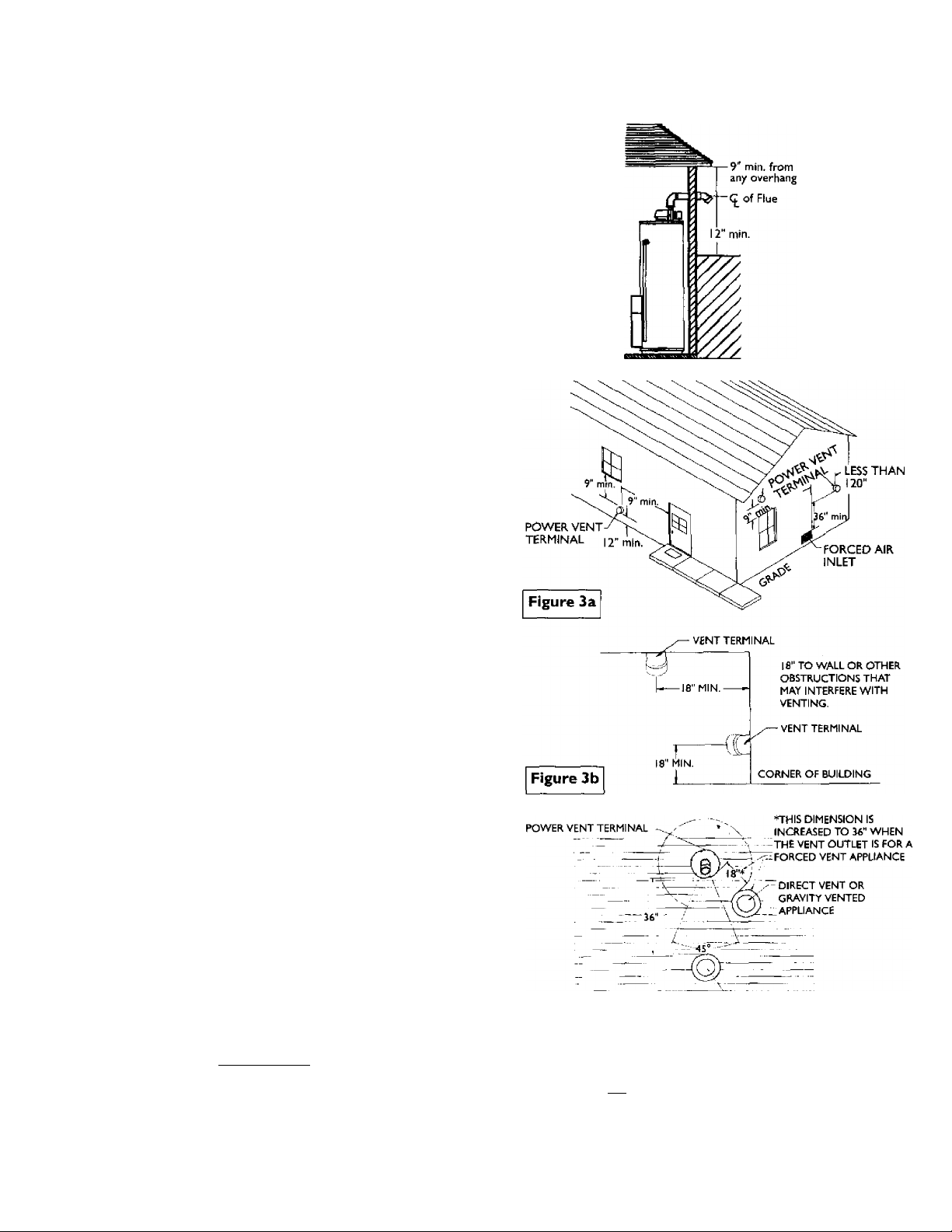
9
12" minimum from the ground, 9" ceiling overhangs. Figure 2.
9
The Power Vent outlet terminal shall terminate at least 36" above
any forced air inlet located within ] 0 feet. Figure 3a.
9
The Power Vent outlet terminal shall terminate at least 9" below, 9"
horizontally from or 9" above any door, window or gravity air inlet
into the building. Figure 3a.
9
18” minimum in all directions from any obstruction that may
interfere. Figure 3b.
9
18" minimum from other gravity or natural appliance outlet vents
when directly above or 135° to either side of center line. Figure 3c.
9
36" minimum from any ourler vents when directly below or 45° to
either side of center line. Figure 3c.
9
36" minimum in all directions from any other forced air appliance
outlet vent. Figure 3c.
9
The location selection must provide clearances for servicing and
proper operation of the water heater. Figure 4.
9
Vent termination must not be within 4 feet of any items such as gas
meters, gas valves or other gas regulating equipment.
9
The venting system must be installed in a manner which allows
inspection of the installation of the venting pipes and joints as well
as periodic inspection after installation as required by ANSI
Standards.
Figure 2
-any other outlet vent
Figure 3c
_______________
AWARNING
_________________
Vent termination must not be within 4 feet of any items such as
gas meters, gas valves or other gas regulating equipment.
AWARNING
Failure to have required clearances between water heater and
combustible material will result in a fire hazard.
10
Must maintain
adequate service
and maintenance
accessibility.
Figure 4
__
_
. TrT'
y' . ' / Range ot degrees
available far vent
pipe installation.
Installation Instructions (cont'd)
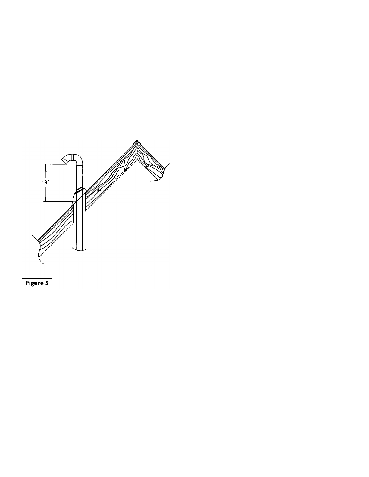
Venting Through Roof - Clearances
# 0" clearance for 3" (or optional 2") PVC, ABS, or CPVC Schedule
40 piping from combustible surfaces.
• The Power Vent outlet terminal shall terminate at least 18" above
the roof surface. Figure 5.
# The location selection must provide clearances for servicing and
proper operation of the water heater. Figure 4,
• The venting system must be installed in a manner which allows
inspection of the installation of the venting pipes and joints as
well as periodic inspection after installation as required by ANSI
Standards. ■
11
Installation Instructions (cont’d)
Combustion Air and Ventilation
for Appliances Located in
Unconfined Spaces
Unconfîned Space is a space whose volume is not less than 50 cubic
feet per 1,000 Bcu per hour of the aggregate input rating of all appli
ances installed in that space. Rooms communicating directly with the
space in which the appliances are installed, through openings not fur
nished with doors, are considered a part of the unconfined space.
In unconfined spaces in buildings, infiltration may be adequate to
provide air for combustion, ventilation and dilution of flue gases.
However, in buildings of tight construction (for example, weather
stripping, heavily insulated, caulked, vapor barrier, etc.), additional air
may need to be provided using the methods described in Combustion
Air and Ventilation for Appliances Located in Confined Spaces.
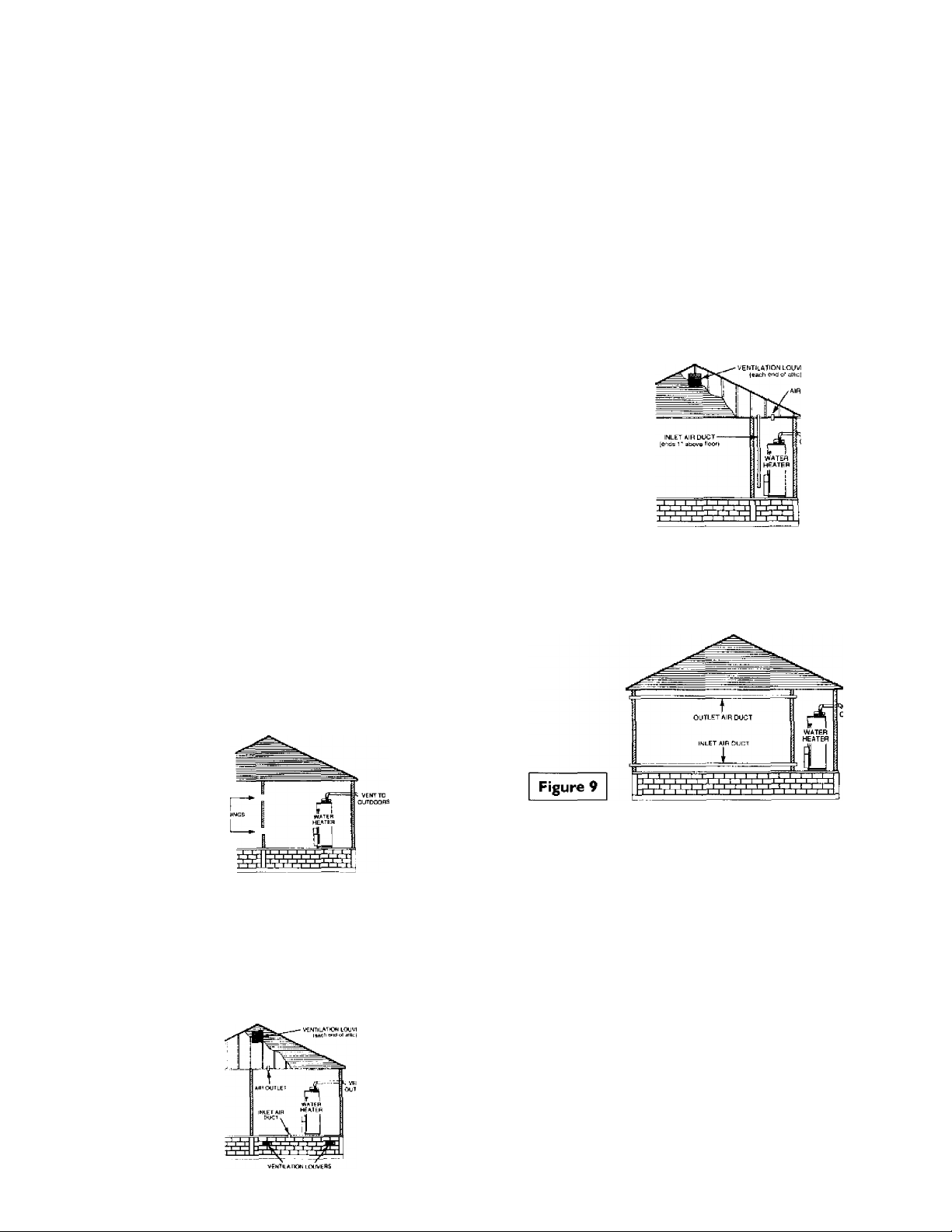
Combustion Air and Ventilation
for Appliances Located in
Confined Spaces
Confined Space is a space whose volume is less than 50 cubic feet per
1,000 Btu per hour of the aggregate input rating of all appliances
installed in that space.
a. ALL AIR FROM INSIDE BUILDINGS:
(See Page 9 Figure 1, and Figure 6 below)
The confined space shall be provided with two permanent open
ings communicating directly with an additional room(s) of suffi
cient volume so that the combined volume of all spaces meets the
criteria for an unconfined space. The total input of all gas utiliza
tion equipment installed in the combined space shall be considered
in making this determination. Each opening shall have a minimum
free area of one square inch per 1,000 BTU per hour of the total
input rating of all gas utilization equipment in the confined space,
but not less than 100 square inches. One opening shall commence
within 12 inches of the top and one commencing within 12 inches
of the bottom of the enclosure.
1. When directly communicating with the outdoors, each opening
shall have a minimum free area of 1 square inch per 4,000 BTU
per hour of total input rating of all equipment in the enclosure.
(Sec Figure 7.)
2. When communicating with the outdoors through vertical ducts,
each opening shall have a minimum free area of 1 square inch
per 4,000 BTU per hour of total input rating of all equipment in
the enclosure. (See Figure 8.)
Figure 8
3. When communicating with the outdoors through horizontal
ducts, each opening shall have a minimum free area of 1 square
inch per 2,000 BTU per hour of total input rating of all equip
ment in the enclosure. (See Figure 9.)
Figure 6
b. ALL AIR FROM OUTDOORS: (see Figures 7-9)
The confined space shall be provided with two permanent open
ings, one commencing within 12 inches of the top and one com
mencing within 12 inches from the bottom of the enclosure.
The openings shall communicate directly, or by ducts, with the
outdoors or spaces (crawl or attic) that freely communicate with
the outdoors.
Figure 7
4. When ducts are used, they shall be of the same cross-sectional area
as the free area of the openings to which they connect. The mini
mum short side dimension of rectangular air ducts shall not be
less than 3 inches. (See Figure 9.)
5. Louvers and Grilles: In calculating free area, consideration shall be
given to the blocking effect of louvers, grilles or screens protect
ing openings. Screens used shall not be smaller than !4 inch mesh.
If the free area through a design of louver or grille is known, it
should be used in calculating the size opening required to provide
the free area specified. If the design and free area is not known, it
may be assumed that wood louvers will be 20-25 percent free area
and metal louvers and grilles will have 60-75 percent free area.
Louvers and grilles shall be fixed in the open position or inter
locked with the equipment so that they are opened automatically
during equipment operation.
6. Special Conditions Created by Mechanical Exhausting or
Fireplaces; Operation of exhaust fans, ventilation systems, clothes
dryers or fireplaces may create conditions requiring special atten
tion to avoid unsatisfactory operation of installed gas utilization
equipment.
12
Installation Instructions (cont’d)
Water Piping
A WARNING
HOTTER WATER CAN SCALD; Water heaters are intended to
produce hot water. Water heated to a temperature which will
satisfy clothes washing, dish washing, and other sanitizing needs
can scald and permanently injure you upon contact. Some peo
ple are more likely to be permanently injured by hot water than
others. These include the elderly, children, the infirm, or physically/mentally handicapped. If anyone using hot water in your home
fits into one of these groups or if there is a local code or state law
requiring a certain temperature water at the hot water tap, then
you must take special precautions. In addition to using the lowest
possible temperature setting that satisfies your hot water needs,
a means such as a mixing valve, should be used at the hot water
taps used by these people or at the water heater. Mixing valves
are available at plumbing supply or hardware stores. Follow man
ufacturers instructions for installation of the valves. Before
changing the factory setting on the thermostat, read the
‘Temperature Regulation” section in this manual.
This water heater shall not be connected to any heating systems
or component(s) used with a non-potable water heating appli
ance.
If a water heater is installed in a closed water supply system;
such as one having a back-flow preventer, check valve, water
meter with a check valve, etc... in the cold water supply; means
shall be provided to control thermal expansion. Contact the
local utility or local Sears Service Center on how to control this
situation.
2. Look at the top cover of the water heater. The cold water
inlet is marked cold. Put two or three turns of teflon tape
around the threaded end of the threaded-to-sweat coupling
and around both ends of the M" threaded nipple. Using flexi
ble connectors, connect the cold water pipe co the cold water
inlet of the water heater.
NOTE: This water heater is insulated to minimize heat
loss from the tank. Further reduction in heat loss can be
accomplished, by insulating the hot water lines from the
water heater.
INSTALLATION COMPLETED USING
SEARS INSTALLATION KIT
COLD INLET
NOTE; To protect against untimely corrosion of hot and
cold water nttings, it is strongly recommended that dielec
tric unions or couplings be installed on this water heater
when connected to copper pipe.
The illustration shows the attachment of the water piping to the
water heater. The water heater is equipped with ’A inch water
connections.
NOTE; If using copper tubing, solder tubing to an adapter
before attaching the adapter to the cold water inlet connec
tion. Do not solder the cold water supply line directly to the
cold water inlet or it will harm the dip tube.
1. Look at the top cover of the water heater. The hot water outlet is
marked hot. Put two or three turns of teflon tape around the
threaded end of the threaded-to-sweat coupling and around both
ends of the X" threaded nipple. Using flexible connectors, con
nect the hoc water pipe co the hoc water outlet on the water
heater.
13
Installation Instructions (cont’d)
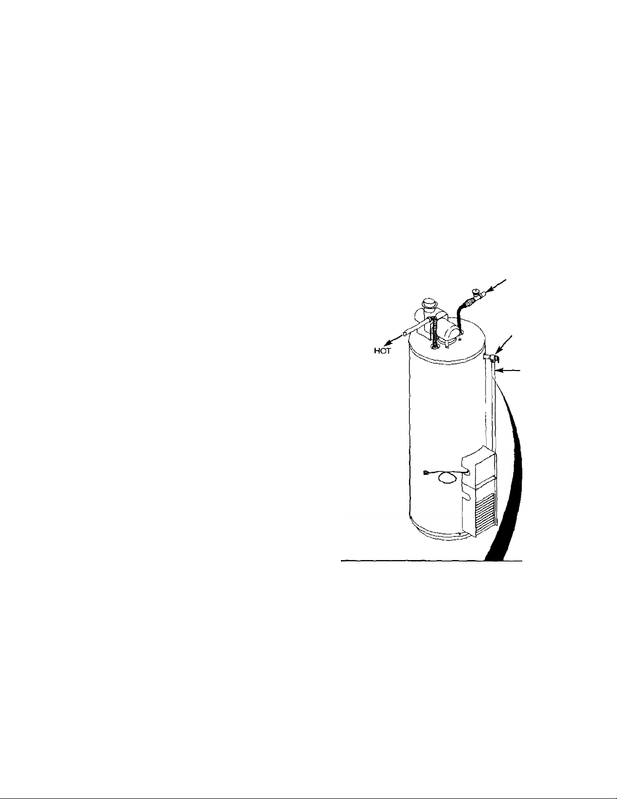
Temperature-Pressure Relief Valve
▲WARNING
At the time of manufacture this water heater was provided
with a combination temperature-pressures relief valve certified
by a nationally recognized testing laboratory that maintains
periodic inspection of production of listed equipment or mate
rials, as meeting the requirements for Relief Valves and
Automatic Gas Shutoff Devices for Hot Water Supply Systems,
and the latest edition of ANSI Z2I.22 and the code require
ments of ASME. If replaced, the valve must meet the require
ments of local codes, but not less than a combination tempera
ture and pressure relief valve certified as meeting the require
ments for Relief Valves and Automatic Gas Shutoff Devices for
Hot Water Supply Systems, ANSI Z21.22 by a nationally recog
nized testing laboratory that maintains periodic inspection of
production of listed equipment or materials.
The vsdve must be marked with a maximum set pressure not
to exceed the marked hydrostatic working pressure of the
water heater (ISO lb$./sq. in.) and a discharge capacity not less
than the water heater input rate as shown on the model rating
plate. (Electric heaters - watts divided by 1000 x 3415 equal
BTU/Hr. rate.) ^
Your local jurisdictional authority, while mandating the use of a
temperature-pressure relief valve complying with ANSI Z2I.22
and ASME, may require a valve model different from the one
furnished with the water heater.
Compliance with such local requirements must be satisfied by
the installer or end user of the water heater with a locally pre
scribed temperature-pressure relief valve installed in the desig
nated opening in the water heater in place of the factory fur
nished valve.
For safe operation of the water heater, the relief valve must not
be removed from it’s designated opening or plugged.
The temperature-pressure relief valve must be installed directly
into the fitting of the water heater designated for the relief valve.
Position the valve downward and provide tubing so that any dis
charge will exit only within 6 inches above, or at any distance
below the structural floor. Be certain that no contact is made
with any live electrical part The discharge opening must not be
blocked or reduced in size under any circumstances. Excessive
length, over 30 feet, or use of more than four elbows can cause
restriction and reduce the discharge capacity of the valve.
No valve or other obstruction is to be placed between the relief
valve and the tank. Do not connect tubing directly to discharge
drain unless a 6" air gap is provided. To prevent bodily injury, haz
ard to life, or property damage, the relief valve murt be allowed
to discharge water in quantities should circumstances demand. If
the discharge pipe is not connected to a drain or other suitable
means, the water flow may cause property damage.
The Discharge Pipe:
• Must not be smaller in size than the outlet pipe size of the
valve, or have any reducing couplings or other restrictions.
• Must not be plugged or blocked.
• Must be of material listed for hot water distribution.
• Must be installed so as to allow complete drainage of both
the temperature-pressure relief valve, and the discharge
pipe.
• Must terminate at an adequate drain.
• Must not have any valve between the relief valve and tank.
▲ WARNING
The temperature-pressure relief valve must be manually
operated at least once a year. Caution should be taken to
ensure that (I) no one is in front of or around the outlet of
the temperature-pressure relief valve discharge line, and (2)
the water manually discharged will not cause any bodily
injury or property damage because the water may be
extremely hot
If after manually operating the valve, it fails to completely
reset and continues to release water, immediately close the
cold water inlet to the water heater, follow the draining
instructions, and replace the temperature-pressure relief
valve with a new one.
COLD
TEMPERATURE-PRESSURE
RELIEF VALVE
DISCHARGE PIPE
(Do not cap or plug)
PROVIDE A 6" AIR
GAP BETWEEN THE
END OF THE
DISCHARGE PIPE
AND DRAIN
RELIEF VALVE OPENING
At the time of manufacture, this water heater was provided with a combination tem
perature-pressure relief valve listed as complying widi the standard for relief valves and
automatic gas shut-off devices for hot water supply systems, ANSI ZII.2T For safe
operation of the water heater, the relief valve must not be removed from its designated
point of installation or plugged.
Your local jurisdictional authority, while mandating the use of a temperature-pressure
relief valve complying with ANSI ¿21.22 and ASME, may require a valve model different
from the one furnished with the water heater.
Compliance with such local requirements must be satisfied by the installer or end user
of the water heater with a locally prescribed temperature-pressure relief valve installed
in the designated opening in the water heater.
See manual heading -“Temperature-Pressure Relief Valves" for Installation and mainte
nance of relief valve, discharge line, and other safety precautions.
14
 Loading...