

Page 1
Owners
Manual
FOR POTABLE WATER
HEATING ONLY
NOT SUITABLE FOP,
SPACEHEATING
NOT FOR USE IN
MOBILE HOMES
Model No.
153,335816 40 Gal.
153.335845 40 Gal. HighAltitude LR
153.335862 40Gal./R
153.335916 50 Gal.
153.335942 50 Gal. High Altitude I-P.
153.335962 50 Gal. L.R
©
I
POWER MISER TM 9
POWER VENT
GAS WATER HEATER
• Safety Instructions • Care and Maintenance
• Installation • Troubleshooting
• Operation • Parts List
Caution:
Read and Follow
All Safety Rules and
Operating Instructions
Before First Use of
This Product.
For Your Safety
AN ODORANT IS ADDED TO THE GAS USED BY THIS
WATER HEATER
WARNING: If the information in these instructions are not fol-
lowed exactly, a fire or explosion may result, causing property
damage, personal ,nlury or death.
-Do not store or use _as.oline or other fl.a_n.mable vapors and liq-
rods ,n the viomty of th,s or any other appliance.
-WHAT TO DO IF YOU SMELL GAS
Do not try to light any appliance.
Do not touch any electrscal sw,tch; do not use any phone ,n your
buildin£.
• Immeoqately call your gas supplier from a ne,ghbor's phone.
Follow the gas supplier's]nstructions.
• If you can not reach your gas suppl,er, call the fire department.
-Installation and service must be performed by a qualified installer,
service agency or the gas supplier.
• AWARNING 1
Improper Installation, adjustment, alteration, service or maintenance I
can cause DEATH, SERIOUS BODILY INJURY, OR PROPERTY DAM-|
AGE. Refer to this manual for assistance or consult the local Sears/
Service Center or gas utility for further information. |
AWARNING
Flammable vapors may be drawn by air currents from other areas
of the structure to this appliance.
Savethis Manual for Future Reference.
Sears, Roebuck and Co., Hoffman Estates, IL 60179 U.S.A.
AWARNING
READ THE GENERAL SAFETY SECTION BEGINNING ON INSIDE
COVER AND THEN THIS ENTIRE MANUAL BEFORE INSTALLING
OR OPERATING THIS WATER HEATER.
Page 2
Safety Precautions
I_n A,WARNING 1
Improper installation, adjustment, altoratJon, service or [
aintanance can cause death, serious bodily injury, or
property damage. Refer to this manual for assistance or [
onsolt your local Sears Service Center for further[
nformatlon.
AWARNING
WATER HEATERS EQUIPPED FOR ONE TYPE GAS
ONLY: This water heater is equipped for one type gas
only. Check the model rating plate near the gas control
valve for the correct gas. DO NOT USE THIS WATER
HEATER WITH ANY GAS OTHER THAN THE ONE
SHOWN ON THE MODEL RATING PLATE. Failure to
usethe correct gas cancause problems which can result in
DEATH, SERIOUS BODILY INJURY, OR PROPERTY
DAMAGE. If you have any questions or doubts consult
your gassupplier or localutility.
A,WARNING
INSTALLATIONS IN AREAS WHERE FLAMMABLE LIQ-
UIDS (VAPORS) ARE LIKELY TO BE PRESENT OR
STORED (GARAGES, STORAGE, AND UTILITY AREAS,
ETC): Flammable liquids (such as gasoline, solvents,
propane (LP) or butane, etc.), all of which emit flammable
vapors, may be improperly stored or used in suchareas.
The gas water heater pilot light or main burner can Ignite
such vapors. The resulting flashback and fire can cause
death or serious burns to anyone in the area, as well as
property damage.
If installation in such areas is your only option, than the
installation must be accomplished in a way that the pilot
flame and main burner flame are elevated from the floor
at least 18 inches. While this may reduce the chances of
flammable vapors from a floor spill being ignited, gasoline
and other flammable substancesshould never be stored or
used in the same room or area containing a gas water
heater or other open flame or spark producing appliance.
NOTE: Flammable vapors may be drawn by air currents
from other areasof the structure to the appliance.
A, WARNING
If this water heater will be used in beauty shops, barber
shops, cleaning establishments, or serf-service laundries
with dry cleaning equipment, it is imperative that the
water heater or water heaters be installed so that com-
bustion and ventilation air be taken from outside these
areas. Refer to the "Locating The New Water Heater"
section of this manual and also the latest edition of the
National Fuel Gas Code, ANSI 7.223.1, also referred to as
NFPA 54 for specificsprovided concerning air required.
I _,WARNING
A fire can start if co_Hals suchasclothing,
cleaningmaterials,or flammableliquidsam placedagainst
or nexttothe waterheater.
AWARNING
At the time of manufacture this water heater was provid-
ed with a coml_nation temperature-pressures relief valve
certified by a nationally recognized testing laboratory
that maintains periodic inspection of production of listed
equipment or materials, as meeting the requirements
for Relief Valves and Automatic Gas Shutoff Devices for
Hot Water Supply Systems, and the latest edition of
ANSI Z21.2Z and the code requirements of ASME. If
replaced, the valve must meet the requirements of local
codes, but not less than a combination temperature and
pressure relief valve certified as meeting the require-
ments for Relief Valves and Automatic Gas Shutoff
Devices for Hot Water Supply Systems, ANSI Z21.22 by
a nationally recognized testing laboratory that maintains
periodic inspection of production of listed equipment or
materials.
The valve must be marked with a m_imum set pressure
not to exceed the marked hydrostatic working pressure
of the water heater (150 Ibs./sq. in.) and a discharge
capacity not less than the water heater input rate as
shown on the model rating plate. (Electric heaters -
watts divided by 1000 x 3415 equal BTU/Hr. rate.)
Your local jurisdictional authority, while mandating the
use of a temperature-pressure relief valve complying
with ANSI Z21.22 and ASME, may require a valve model
different from the one furnished with the water heater.
Compliance with such local requirements must be satis-
fled by the installer or end user of the water heater with
a locally prescribed temperature-pressure relief valve
installed in the designated opening in the water heater in
dace of the factory furnished valve.
For safe operation of the water heater, the relief valve
must not be removed from it's designated opening or
plugged.
The temperature-pressure relief valve must be installed
[directly into the fitting of the water heater designated
for the relief valve. Position the valve downward and pr_
vide tubing so that any discharge will exit only within
inches above, or at any distance below the structural
floor. Be certain that no contact is made with any live
electrical part. The discharge opening must not be
blocked or reduced in size under any circumstances.
Excessivelength, over 30 feet, or use of more than four
elbows can cause restriction and reduce the discharge
capacity of the valve.
No valve or other obstruction is to be placed between
the re ef vave and the tank. Do not connect tub ng
directly to discharge drain unlessa 6" air gap isprovided.
To prevent bodily injury, hazard to life, or property dam-
age, the relief valve must be allowed to discharge water
in quantities should circumstances demand. If the dis-
charge pipe is not connected to a drain or other suitable
means, the water flow may cause property damage.
The Discharge Pipe:
Must not be smaller in size than the oudet pipe size of
the valve, or have any reducing couplings or other
restrictions.
Must not be plugged or blocked.
Must be of material listed for hot water distribution.
Must be installed so as to allow complete drainage of
both the temperature-pressure relief valve, and the
discharge pipe.
Must terminate at an adequate drain.
Must not have any valve between the relief valve and
tank.
2
Page 3
Safety Precautions
AWARNING
A gaswater heater cannot operate properly without the
correct amount of air for combustion. Do not install in a
confined area such a closet, unless you provide air as
shown in the "Locating The Now Water Heater" section.
Never obstruct the flow of ventilation air. If you haveany
doubts or questions at all, call your gas company. Failure
to provide the proper amount of combustion air can result
in a fire or explosion and can cause DEATH, SERIOUS
BODILY INJUR_, OR PROPERTY DAMAGE.
AWARNING
HOTTER WATER CAN SCALD: Water heaters are
intended to produce hot water. Water heated to a tem-
mraturo which will satisfyclothes washing, dish washing,
and other sanitizing needs can scald and permanently
injure you upon contact. Some people are more likely to
be permanently injured by hot water than others. These
include the elderly, children, the infirm, or physicaily/mea.
tally handicapped. If anyone using hot water in your home
fits into one of these groups or if there is a local cede or
state law requiring a certain temperature water at the hot
water tap, then you must take special precautions. In addi-
tion to usingthe lowest possible temperature setting that
satisfies your hot water needs, a means such as a mixing
valve, should be used at the hot water taps used by these
people or at the water heater. Mixing valves are available
at plumbing supply or hardware stores. Follow manufac-
turers instructions for installation of the valves. Before
changing the factory setting on the thermostat, read the
'_l'emperatoro Regulation" section in this manual.
i
This water heater must not be installed directly on car-
peting. Carpeting must be protected by a metal or wood
panel beneath the appliance extending beyond the full
width and depth of the appliance by at least 3 inches
(76.2mm) in any direction, or if the appliance is installed
in an alcove or closet, the entire floor must be covered by
the panel. Failure to heed this warning may result in a
fire hazard.
AWARNING
AWARNING
The power vent water heater requires its own (separate)
venting system. It cannot be connected to an existing vent
pipe or chimney. It must be terminated horizontally to the
outdoors. Failure to properly install the ventingsystem can
result in asphyxiation, a fire or explosion and can cause
DEATH, SERIOUS BODILY INJURY,OR PROPERTY DAM-
AGE.
AWARNING
No vent damper installation iscompatible with this power
vented water heater design.No vent damper, whether it is
operated thermally or otherwise isto he installed on this
power vented water heater. Alteration of any part of the fac-
tory-furnished vent assemblycould result inimproper oper-
ation due to restriction of flue gases, spillage of flue gases
and may causecarbon monoxide poisoning.
_,WARNING
Soot build-up indicates a problem that requires correc-
tion before further use. Turn "off" gas to water heater
and leave "off" until repairs are made, because failure to
correct the cause of the sooting can result in a fire or
explosion causing DEATH, SERIOUS BODILY INJURY,
OR PROPERTY DAMAGE.
AWARNING
BEFORE LIGHTING [PROPANE (L.P.) GAS WATER
HEATERS]: Propane (I-R) gas is heavier than air. Should
there be a leak in the system, the gas will settle near the
ground. Basements, crawl spaces, skirted areas under
mobile homes (even when ventilated), closets and areas
below ground level will serve as pockets for the accumula-
tion of this gas. Before attempting to light or relight the
water heater's pilot or turning on a nearby electrical light
switch, be absolutely sure there is no accumulated gas in
the area. Search for odor of gas by sniffingat ground level
in the vicinity of the appliance. If odor is detected, follow
steps indicated at "For Your Safety" on the cover page of
this manual then leave the premises.
AWARNING
•The appliance and its individual shutoff valve must be dis-
connected from the gassupply piping system during any
pressure testing of the gas system at test pressures in
excess of I/2 pound per square inch (3.5kPa).
•The appliance must be isolated from the gas supply pip-
ing system by closingits individual manual shutoff valve
during any pressure testing of the gas supply piping sys-
tem at test pressures equal or less than I/2 pound per
square inch (3.SkPa).
_,WARNING
Chemical vapor corrosion of the flue and vent system
may occur if air for combustion contains certain chemical
vapors.Spray can propellants, cleaning solvents,refrigera-
tor and air conditioner refrigerants, swimming pool
chemicals, calcium and sodium chloride, waxes, bleach,
and process chemicals are typical compounds which are
potentially corrosive.
Obstructedor deteriorated vent systemsmay present
serioushealthriskor asphyxiation.
3
AWARNING a
Safety Precautions continued on page 4.
Page 4
Safety Precautions
&WARNING I
The water heater with draft hood installed must be prep- I
erly vented to a chimney which terminates outdoors. I
Never operate the water heater unless it is vented to the
outdoors and has adequate air supply to avoid risks of
improper operation, expos on or asphyxiation.
_,WARNING
Minimum clearances between the water heater and €om-
bustible construction are 0" at the sidesand rear, 5" at the
front, and 0" from the vent pipe. Clearance from the top
of the jacket is 14" on most models. Note that s lesser
dimension may be allowed on some models. Refer to the
label on the water heater adjacent to the gascontrol valve
for all clearances.
•,WARNING ]
Do not use this appliance if any part of it has been under|
water. Immediately call a Sears Service Technician to|
inspect the appliance and to replace tee gascontrol or any|
part of the bureer system wh ch hasbeen under water. |
AWARNING
HYDROGEN GAS: Hydregen gas canbe produced in a hot
water system that has not been used for a long period of
time (generally two weeks or more). Hydrogen gas is
extremely flammable and explosive. To prevent the possi-
bility of injury under these conditions, we recommend the
hot water faucet be opened for several minutes at the
kitchen sink before any electrical appliances which are
connected to the hot water system are used (such as a
dishwasher or washing machine). If hydrogen gas is pre-
sent, there will probably be an unusualsound similar to air
escapin_through the pipe as the hot water faucet is
opened. There must be no smoking or open flame near
the faucet atthe time it isopen.
I AWARNING ]
Venttermination mustnot be within 4 feet of any items|
suchas gas meters, gasvalvesor other gasregulating|
equipment. |
&,CAUTION
WATER HEATERS EVENTUALLY LEAK: Installation of
the water heater must be accomplished in such a manner
that if'the tank or any connections should leak, the flow of
water will not cause damage to the structure. When such
locations cannot be avoided, a suitable drain pan should
be installed under the water heater, Drain pansare avail-
able at your local Sears store. Such a drain pan must be
not greater than 1I/2 inches deep. have a minimum
length and width of at least 2 inches greater than the
water heater dimensions and must be piped to an ade-
quate drain. The pan must not restrict combustion air
flow. Under no circumstances is the manufacturer or
Sears to be held liable for any water damage in connec-
tion with this water heater.
AWARNING
INSULATING JACKETS: When instailin S an external
water heater insulation jacket on a gaswater heater:
• DO NOT cover the temperature-pressure relief valve.
• DO NOT put insulation over any part of the top of the
gaswater heater.
• DO NOT put insulation over the gascontrol valve or gas
control vaivefbumer cover, or any access Meas to the
burner, i
DO NOT let insulation around the gas water heater to
get within 8 inches of the floor (air must get to the
burner).
DO NOT cover or remove operating instructions, and
safety related warning labelsand materials affixed to the
water heater.
:allure to heed thiswill result in the possibilityof afire or
explosion.
4
Page 5
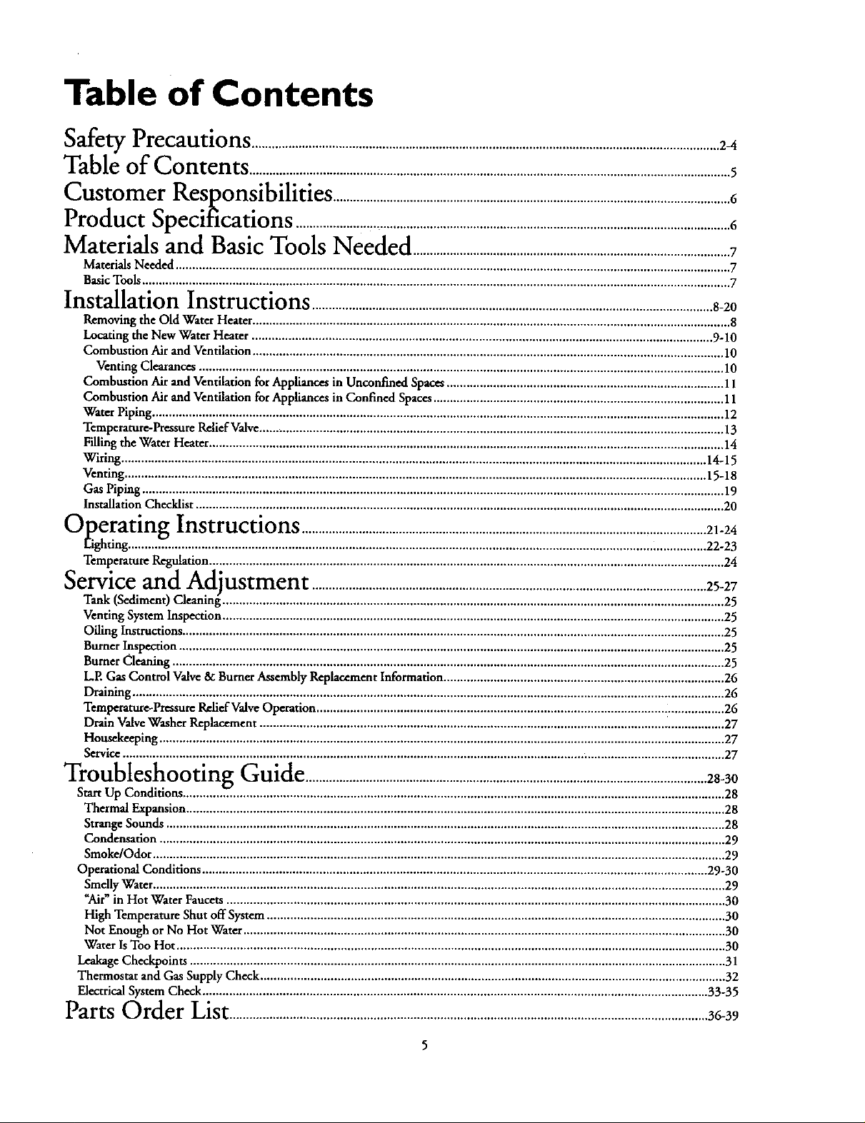
Table of Contents
Safety Precautions ............................................................................................................................................24
Table of Contents ................................................................................................................................................5
Customer
Product Specitlcations'_"..................................................................................................................................6
Materials and Basic Tools Needed ...............................................................................................7
Materials Needed ...................................................................................................................................................................... 7
Basic Tools ................................................................................................................................................................................ 7
Installation Instructions ........................................................................................................................8-20
Removing the Old Water Heater ............................................................................................................................................... 8
Locating the New Water Heater .......................................................................................................................................... 9-10
Combustion Air and Ventilation ............................................................................................................................................. 10
Venting Clearances ............................................................................................................................................................. 10
Combustion Air and Ventilation for Appliances in Unconfined Spaces ................................................................................... 11
Combustion Air and Ventilation for Appliances in Confined Spaces ....................................................................................... 11
Water Piping ........................................................................................................................................................................... 12
Temperature-Pressure Relief Valve........................................................................................................................................... 13
Filling the Water Heater .......................................................................................................................................................... 14
Wiring ............................................................................................................................................................................... 14-15
Venting .............................................................................................................................................................................. 15-18
Gas Piping .............................................................................................................................................................................. 19
Installation Checklist .............................................................................................................................................................. 20
""Overatln_ Instructions .........................................................................................................................21-24
-- 1"_Eighting ........................................................................................................................................................... i.;............... 22-23
Temperature Regulation .......................................................................................................................................................... 24
Service and Adjustment ...................................................................................................................... 25-27
Tank (Sediment) Cleaning ...................................................................................................................................................... 25
Venting System Inspection ...................................................................................................................................................... 25
Oiling Instructions .................................................................................................................................................................. 25
Burner Inspection ................................................................................................................................................................... 25
Burner Cleaning ..................................................................................................................................................................... 25
L.E Gas Control Valve & Burner Assembly Replacement Information .................................................................................... 26
Draining ................................................................................................................................................................................. 26
Temperature-Pressure Rehef Valve Operation .......................................................................................................................... 26
Drain Valve Washer Replacement ........................................................................................................................................... 27
Housekeeping ......................................................................................................................................................................... 27
Service .................................................................................................................................................................................... 27
Responsibilities- .......................................................................................................................6
Troubleshooting Guide ........................................................................................................................28-30
Start Up Conditions .................................................................................................................................................................. 28
Thermal Expansion ................................................................................................................................................................. 28
Strange Sounds ....................................................................................................................................................................... 28
Condensation ......................................................................................................................................................................... 29
Smoke/Odor ........................................................................................................................................................................... 29
Operational Conditions ....................................................................................................................................................... 29-30
Smelly Water ........................................................................................................................................................................... 29
"Air" in Hot Water Faucets ..................................................................................................................................................... 30
High Temperature Shut off System ......................................................................................................................................... 30
Not Enough or No Hot Water ................................................................................................................................................ 30
Water Is Too Hot .................................................................................................................................................................... 30
Leakage Checkpoints ................................................................................................................................................................ 31
Thermostat and Gas Supply Check ........................................................................................................................................... 32
Electrical System Check ....................................................................................................................................................... 33-35
Parts
"-'-OrderList ...............................................................................................................................................36-39
Page 6
Customer Responsibilities
Thank You p°rch in aSo rsw terheater.Properly
installedand maintained,it shouldgweyouyearsof troublefreeser-
vice.If youshoulddecidethatyouwant the newwaterheaterprofes-
sionallyinstalledbySearscall the localSearsServiceCenter orany
Scarsstore.Theywillarrangeforprompt, qualityinstallationbySears
authorizedcontractors.
AbbreviationsFound In This Instruction Manual
I.A.S.- InternationalApprovalServices,A Division of CSA
A.N.S.I. - AmericanNational Standards Institute
AWARNING
This gas-fired water heater is design certified by the
International Approval Services, A Division of CSA under
American National Standard/CSA Standard for GasWater
Heaters ANS Z21.10.1 • CSA 4.1 (latest edition). The
installation must conform with this manual, Local Codes
and with the latest edition of the National Fuel Gas Code
ANSI Z223.1.
This publication is available from your localgovernment or
public library, gas company, or by writing NFPA,
Batterymarch Park, Quincy, MA 02269.
• Readthe "SafetyPrecautions"section, pages 2 and 3 of this
manual first and then the entire manualc,_efully.If you don t
followthe safety rules, the water heater will not operateprop-
erly. It could cause DEATH, SERIOUS BODILY INJURY
AND/OR PROPERTY DAMAGE.
This manual contains instructions for the installation, opera-
tion, and maintenance of the gas-frred water heater. It also
contains warnings through out the manual that you must read
and be aware of. All warnings and all instructions are essential
to the proper operation of the water heater and your safety.
Since we cannot put everything on the first few pages, READ
THE ENTIRE MANUAL BEFORE ATTEMPTING TO
INSTALL OR OPERATE THE WATER HEATER.
• The installation must conform with the instructions in this
manual; gas company rules; and Local Codes, or in the
absence of Local Codes, with the latest edition of the National
Fuel Gas code, ANSI Z223.1, also referredto as NFPA 54.
This publication is available from your local government or
public library or gas company or by writing NFPA,
Battetymarch Park,Quincy, MA 02269.
• If after reading this manualyou have any questions or do not
understand any portion of the instructions, call the Sears
Service Center.
heater. Correct combustion, vent action, and vent pipe instal-
lation are very important in preventing death from possible
cathon monoxide poisoning and fires.
i arefully plan the place where you are going to put the water
Examine the location to ensure the water heater complies with
the "Locating the New Water Heater" section in this manual.
For California installation this water heater must be braced,
anchored, or strapped to avoid falling or moving during an
earthquake. See instructions for correct installation proce-
dures. Instructions may be obtained from your local dealer,
wholesaler, public utilities or California Office of the State
Architect, 400 P Street, Sacramento, CA 95814.
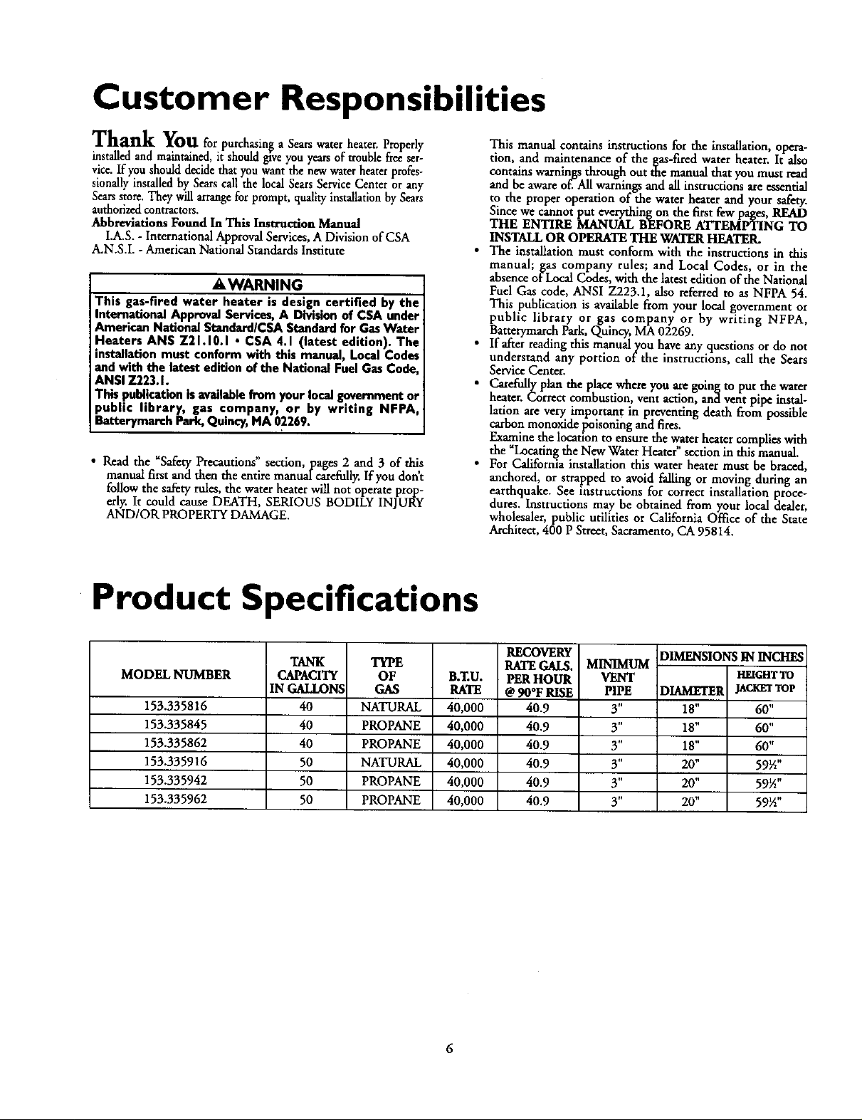
Product Specifications
MODEL NUMBER
153.335816
153.335845
153.335862
153.335916
153.335942
153.335962
TANK
CAPACITY
IN GALLON,'
40
40
40
50
50
50
TYPE
OF
GAS
NATURAL
PROPANE
PROPANE
NATURAL
PROPANE
PROPANE
B.ZU.
RATE
40,000
40,000
40,000
40,000
40,000
40,000
RECOVERY
RATE GM$.
PER HOUR
@ 900F RISE
40.9
40.9
40.9
40.9
40.9
40.9
MINIMUM
VENT
PIPE
3"
3"
3"
3"
3"
3"
DIMENSIONS IN INCHES
HEIGHTTO
DIAMETER JAC_'r TOp
18" 60"
18" 60"
18" 60"
20" 59½"
20" 59½"
20" 59½"
6
Page 7
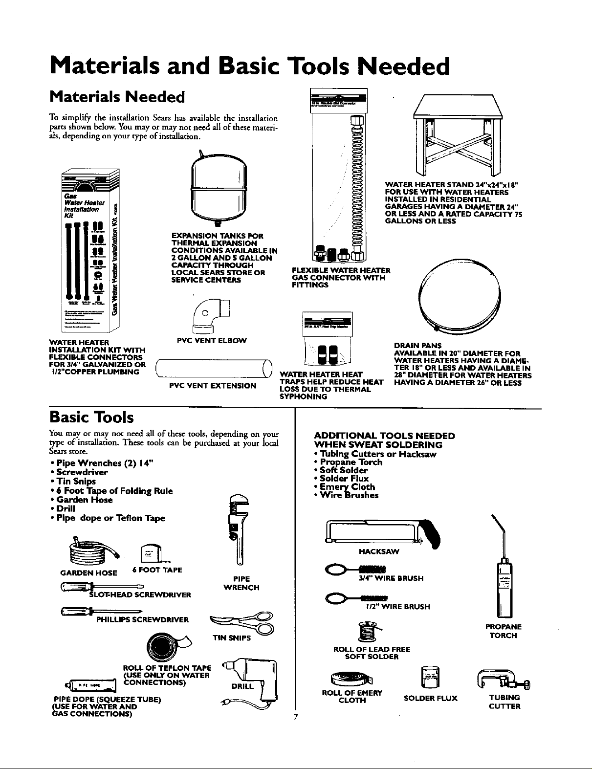
Materials and Basic Tools Needed
Materials Needed
To simplify the installation Sears has availablethe installation
parts shownbelow.You may or may not need allof these materi-
als, dependingonyour type of installation.
WATER H EATER STAND 24"x24"xl 8"
FOR USE WITH WATER HEATERS
W#hDr I¢_ttu"
I_stallatlon
II
ii
EXPANSION TANKS FOR
THERMAL EXPANSION
CONDITIONS AVAILABLE IN
2 GALLON AND 5 GALLON
CAPACITY THROUGH
LOCAL SEARS STORE OR
SERVICE CENTERS
FLEXIBLE WATER HEATER
GAS CONNECTOR WITH
FITTINGS
INSTALLED IN RESIDENTIAL
GARAGES HAVING A DIAMETER 24"
OR LESS AND A RATED CAPACITY 75
GALLONS OR LESS
WATER HEATER
INSTALLATION KIT WITH
FLEXIBLE CONNECTORS
FOR 3/4" GALVANIZED OR
I/2"COPPER PLUMBING
PVC VENT ELBOW
PVC VENT EXTENSION
Basic Tools
Youmay or may not need all of these tools, dependingon your
type of installation. These tools can be purchased at your local
Searsstore.
• Pipe Wrenches (2) 14"
Screwdriver
Tin Snips
6 Foot Tape of Folding Rule
Garden Hose
Drill
Pipe dope or Teflon Tape
GARDEN HOSE 6 FOOT TAPE
SLOT-HEAD SCREWDRIVER
PHILLIPS SCREWDRIVER
ROLL OF TEFLON TAPE
(USE ONLY ON WATER
CONNECTIONS)
PIPE DOPE (SQUEEZE TUBE)
USE FOR WATER AND
_AS CONNECTIONS)
PIPE
WRENCH
TIN SNIPS
WATER HEATER HEAT
TRAPS HELP REDUCE HEAT
LOSS DUE TO THERMAL
SYPHONING
ADDITIONAL TOOLS NEEDED
WHEN SWEAT SOLDERING
• Tubing Cutters or Hacksaw
• Propane Torch
• Soft Solder
• Solder Flux
• Emery Cloth
• Wire Brushes
HACKSAW
3/4" WIRE BRUSH
112" WIRE BRUSH
ROLL OF LEAD FREE
SOFT SOLDER
ROLL OF EMERY
CLOTH SOLDER FLUX TUBING
DRAIN PANS
AVAILABLE IN 20" DIAMETER FOR
WATER HEATERS HAVING A DIAME-
TER 18" OR LESS AND AVAILABLE IN
28" DIAMETER FOR WATER HEATERS
HAVING A DIAMETER 26" OR LESS
\
PROPANETORCH
CUTTER
Page 8
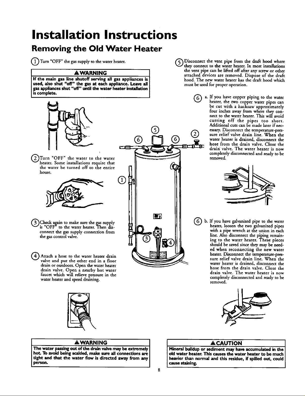
Installation Instructions
Removing the Old Water Heater
_OFF" the the heater.
Turn gassupply to water
AWARNING
If the maingas line shutoffservingall gas appliances is[
used,alsoshut "off" the gasat each appliance.Leaveall I
gasappliancesshut "off" untilthewater heaterinstallation
scompere.
® ®
_OFF" the the
Turn water to water
heater. Some installations require that
the water he turned off to the entire
house.
®
Disconnect the vent pipe from the draft hood where
they connect to the water heater. In most installations
the vent pipe can belifted off after anyscrew or other
attached devices are removed. Dispose of the draft
hood. The new water heater has the drafthood which
must be used for proper operation.
Q a.
If you have copper piping to the water
heater, the two copper water pipes can
be cut with a hacksaw approximately
four inches away from where they con-
nect to the water heater. This will avoid
cutting off the pipes too short.
Additional cuts can be made later if nec-
essary. Disconnect the temperature-pres-
sure relief valve drain line. When the
water heater is drained, disconnect the
hose from the drain valve. Close the
drain valve. The water heater is now
completely disconnected and ready to be
removed.
GCheck a_ain to makesure the gassupply
is OFF to the water heater. Then dis-
connect the gas supply connection from
the gascontrol valve.
a to
Attach hose the heater drain
valve and put the other end in a floor
drain or outdoors. Open the water heater
drain valve. Open a nearby hot water
faucet which will relieve pressure in the
water heater and speed draining.
water
AWARNING I
The water passingout of the drain valve may be extremely I
bet. To avoid being scalded, make sum all connections are I
tight and that the water Bow is directed away from any
persoo.
®h
If you have galvanized pipe to the water
heater, loosen the two galvanized pipes
with a pipe wrench at the union in each
line. Also disconnect the piping remain-
ing to the water heater. These pieces
should be saved since they may be need-
ed when reconnecting the new water
heater. Disconnectthe temperature-pres-
sure relief valve drain line. When the
water heater is drained, disconnect the
hose from the drain valve. Close the
drain valve. The water heater is now
completely disconnected and ready to be
removed.
ACAUTION I
Mineral buildup or sediment may have accumulated in the J
old water heater. This causes the water heater to be much J
heavier than normal and this residue_ if spilled out, could
cause staining. I
8
Page 9
Installation Instructions
Locating the New Water
Heater
You should carefully choose an indoor location for the new water
heater, because the placement is a very important consideration
for the safety of the occupants in the building and for the most
economical use of the appliance. TI_ water heater is not for
me in mobile homes or outdoor installation.
Whether replacing an old water heater or putting the water
heater in a new location, the following critical points must be
observed.
1. The location selected should be indoors as close as practical
to the vent termination point, and as centralized with the
water piping system as possible, The water heater, as all water
heaters, willeventually leak. Do not install without adequate
drainage provisions where water flow will cause damage.
2, The vent piping cannot exceed a total of 35 feet including
vertical and horizontal runs and have no more than 3 elbows.
It cannot slope downward and horizontal runs require ¼" per
foot rise. All horizontal runs require adequate support at 3½
feet intervals.
3. The water heater requires its own (separate) venting system.
It mot be connected to an existing ventpipe or chimney.
It must terminate horizontally to the outdoors. Whenever
possible terminate the vent on the leaward side of the build-
ing. NOTE: Condensation may be created, at times, as the
combustion gases _it the vent cap and discoloration of
surfaces in proximity to the vent cap may occur.
&WARNING
The powerventwater heater requiresitsown(separate)veatin_
system.It cannotbe connectedto anexistingventpipeorchim-
ne_ It rnust betormieatod horizontellyto theontdoor& Failureto
properiyinstalltheventingsystemon result inasphlndati_ alira
or explosionand can causeDEATH, SERIOUS BODILY INJUI_,
OR PROPERTYDAMAGF.
4. The water heater comes equipped with a 5 foot power cord
which can be used to connect to a 110/120 volt power
source if(l) local codes allow, and (2) there is a three prong
receptacle available.
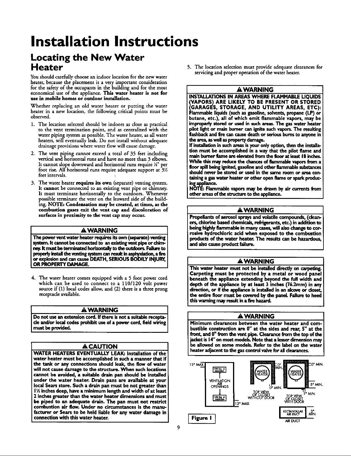
5. The location selection must provide adequate dearances for
servicing and proper operation of the water heater.
a_WARNING
INSTALLATIONS IN AREASWHERE FLAMMABLELIQUIDS
VAPORS) ARE LIKELY TO BE PRESENT OR STORED
GARAGES, STORAGE, AND UTILITY AREAS, ETC):
:lammableliquids(suchasgasoline,solvents,propane(LP) or
butane, etc.), all of which emit flammable vapors, may be
improperlystoredor usedin suchareas.The gaswater heater
pilotlight or main burner can ignitesuchvapor_The reselting
flashbackand Ere cancausedeath or seriousburnsto anyonein
the arna,aswellas prapertydamage.
If installationin suchareasisyour onlyoption,then the iest;dla-
tion must be accomplished in a way that the pilot tlame and
nminbumerflame aure_ frem thefloor at lexst 18inche_
Wh_ this may reduce the cbences of flammable vapers from a
Ilonrspillbeing ignited,gasolineandotherflammablesubstances
shouldneverbe storedor usedin the same room or area con-
teining a gaswater heater or other openflameor sparkproduc-
ingappiiance.
NOTE: Flammable vaporsmay be drawn by air cmxentsfrom
other areasofthe structureto the appliance.
AWARNING
Propellantsof aerosol spraysand volatile compounds,(dean-
or_ chlorinebasedchemicals,refrigerants,etc.) inadditionto
being highlyflammable in many cases,will alsochangeto cor-
rosive hydrochloric acid when exposed to the combustion
products of the water heater. The resultscan be hazardon_
and alsocauseproductfailure.
AWARNING
This water heater must not be installeddirectlyon carpeting.
Carpeting must be protected by a metal or wood panel
beneath the appliance extending beyond the full width and
depth of the applianceby at least 3 inches(76.2mm) in an)
diredion, or if the applianceis iestalledin an alcoveor dosot
the emtre floormust be coverndby the penel. Failureto hne_
this waroingmayresultin afire hazard,
AWARNING ]
Do not usean exteesi_not a suitablerecapta.I
de and/or localcodesprohibituseof a power cord,field wiring
must beprovided,
A, CAUTION
WATER HEATERS EVENTUALLY LEAK: Installation of the
water heater must he accomplished in sucha manner that if
the tank or any connections should leak, the flow of water
will not causedamage to the structure. When suchlocations
cannot be avoided, a suitable drain pan should be installed
under the water heater. Drain pans are available at your
local Searsstore. Sucha drainpan must he not greater than
I% inchesdeep, havea minimum length and width of at least
2 Inchesgreater than the water heater dimensionsand must
be piped to an adequate drain. The pan must not restrict
combustion air flow. Under no circumstancesis the manu-
facturer or Sears to be held liable for any water damage In
connectionwith this water heater.
A,WARNING
Minimum clearances between the water heater and com-
bustible construction am 0" at the sidesand rear,5" at the
frnnt,and 0" from the vent pipe. CI_ frnm the top of the
jacketis 14"on mostmodels.Note that alesserdimensionmay
be allowed on some models.Refer to the label on the water
heater adjacentto the gascontrolvalvefor all clearances.
12"M_
VENI_TION
OPENINGS
WITHOUTDOOR Of CLO_V_T
[2" MAX. WITH DOOR
Figure I ]
O"t_N. _ "
TCP VIE
OF CLOSV_/T TOP VlE 1" MIN.
II
AIRDUCT
Page 10
Installation Instructions (cont'd)
AWARNING
A gaswater heater cannotoperate properly without the cor-
rect amount of air for combustion,Do not installin a con-
fined area such a closet, unlessyou provide air as shown in
the "Locating The New Water Heater" section. Never
obstruct the flow of ventilationair, If you have any doubtsor
questionsat all, call your gascompany.Failure to providethe
proper amount ofcombustionair canresult in a fire or explo-
sionand can causeDEATH, SERIOUS BODILY INJUR_,OR
PROPERTY DAMAGE.
AWARNING
If thiswater heater will be usedin beautyshops,barber shops,
cleaning establishments, or self-service laundries with dry
deaningequipment, it is imperative that the water heateror
water heaters be installedsethat _ andvanttlation
air be taken from outsidedmseareal Rofer to the "LoattMg
Tbe New Way_erHeater" sectionof this manuai and aise the
latesteditionoftbe NationalFuel GasCede,ANSI 7.223.1,also
referred to as NFPA 54 for specific_providedconcerningair
required.
Figure 2 ]
18" min. from
any overhang
- C-p.of Flue
12" rain.
._THAN
120"
Combustion Air and Ventilation
When determining the installation location for apower vent
water heater, snow accumulation and driftingshouldbe consid-
eredin areaswhere applicable.
VENTING CLEARANCES
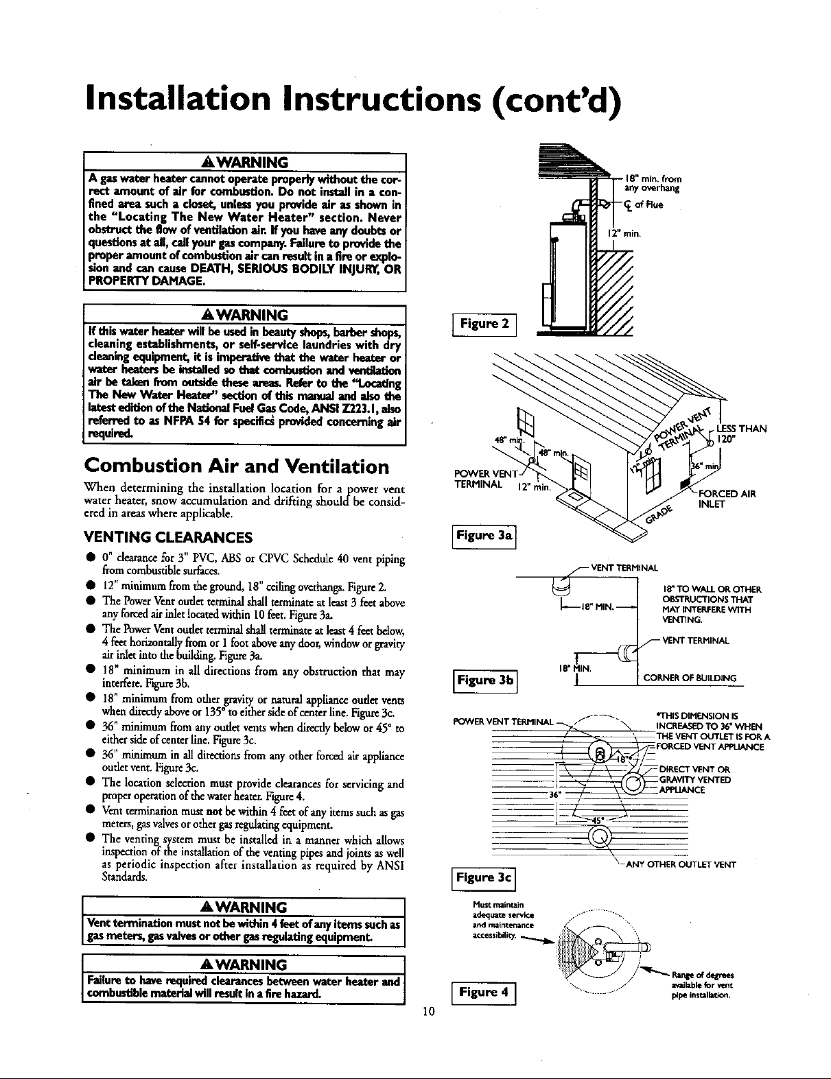
• O" dearance for 3" PVC, ABS or CPVC Schedule 40 vent piping
from combustible surfaces.
• 12" miuimum fromtheground, 18"ceding overhangs. Figure2.
• The PowerVent outlet terminal shall terminate at least3 feet above
anyforced air inletlocatedwithin 10feet. Figure 3a.
• The PowerVent outlet terminal shall terminate at least4 f_et below,
4 feet horizontally from or 1 foot aboveany door,window or gravity
air inlet into the building.Figure3a.
• 18" minimum in all directions from any obstruction that may
interfere.Figure 3b.
• 18" minimum from other gravity or natural appliance oudet vents
W " o ....
hen directly above or 135 m either sideof center line. Ftgu_ 3c.
• 36"minimumfrom anyoudetventswhendirectlybelowor 45° to
eithersideofcenterline.Figure3c.
• 36"minimumin alldirectionsfromanyotherforcedairappliance
outletvent.Figure3c.
• The locationselectionmustprovideclearancesfor servicingand
properoperationofthewaterheater.Figure4.
• Ventterminationmustnot bewithin4 feetof anyitemssuchasgas
meters,gasvalvesorothergasregulatingequipment.
• The venting system must be installed in a manner which allows
inspection of the installation of the venting pipes and joints as well
as periodic inspection after installation as required by ANSI
Standards.
AWARNING
Ventterminationmustnotbewithin4feetofanyitemssuchas
gasmeters,ps valvesorothergasregulatingequipment.
AWARNING
Failureto haverequiredclearancesbetweenwaterbeaterand
combustiblemateHaiwillresultin afire hazard.
POWER V
TERMINAL
Figure 3a]
f VENT TERMINAL
18" TO WALL OR OTHER
OBSTRUCTIONS 'I]'IAT
MAY INTERFERE 'WITH
VENTING.
F VENT TERMINAL
IF,gure3 ,
F_3NVER VENT TERMINAL _ _ INCREASED TO 36 _WHEN
._- -_. *TH S DIMENSION IS
/ _ ' THE VENT oLrrLET ISFOR A
_!_ DIRECTVENT OR
CORNER OF BUILDING
FOR_ VENT APPLIANCE
GL_.WP¢ VENTED
\
_-ANY OTHER OUTLET VENT
Figure 3c]
Mustmaintain
adeq_te $erv_e ............ "'--,,,
andmainterklnce / "_,,
accessibility. _ [
available for vent
[ Figure 4 ] ..................... p_peinsulbdon.
10
FORCED AIR
INLET
Page 11
Installation Instructions (cont'd)
Combustion Air and Ventilation
for Appliances Located in
Unconfined Spaces
Uncom°med Space is a space whose volume is not less than 50 cubic
feet per 1,000 Btu per hour of the aggregateinput rating of allappli-
ances installed in that space. Rooms communicating directly withthe
space in which the%.pphancesareinstalled, through openingsnot fur-
nished with doors, areconsidered a part of the unconfined space.
In unconfined spaces in buildings, infiltration may be adequate to
provide air for combustion, ventilation and dilution of flue gases.
However, in buildings of tight construction (for example, weather
stripping, heavily insulated, caulked, vapor barrier, etc.), additional air
may need to be provided using the methods described in Combustion
Air and Ventilation forAppliances Located in Confined Spaces.
Combustion Air and Ventilation
for Appliances Located in
Confined Spaces
Confined Space isa space whose volume is less than 50 cubic feet per
1,000 Btu per hour of the aggregate input rating of all appliances
installed in that space.
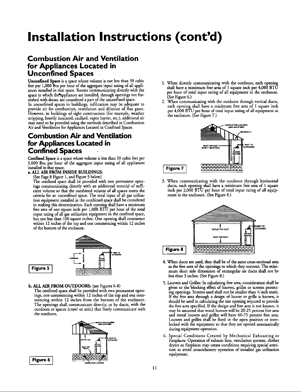
a. ALL AIR FROM INSIDE BUILDINGS:
(See Page8 Figure 1,and Figure 5 below)
The confined space shall be provided with two permanent open-
ings communicating directly with an additional room(s) of suffi-
cient volume so that the combined volume of all spaces meets the
criteria for an unconfined space. The total input of all gas utiliza-
tion equipment installed in the combined space shall be considered
in making this determination. Each opening shall have a minimum
free areaof one square inch per 1,000 BTU per hour of the total
input rating of all gas utilization equipment in the confined space,
but not less than 100 square inches. One openingshall commence
within 12 inches of the top and one commencing within 12 inches
of the bottom of the enclosure.
1. When directly communicating with the outdoors, each opening
shall have a minimum free areaof I square inch per 4,000 BTU
_serhour of total input rating of allequipment in the endosure.
ee Figure 6.)
2. When communicating with the outdoors through vertical ducts,
each opening shall have a minimum free area of 1 square inch
per 4,000 BTU per hour of total input rating of all equipment in
the enclosure. (See Figure7.)
.... , , , , ,
Figure 7 1
3. When communicating with the outdoors through horizontal
ducts, each openingshall have a minimum freeareaof 1 square
inch per 2,000 BTU per hour of total input rating of all equip-
ment in the enclosure.(SeeFigure8.)
VENTIULTK_d LOU_
WA_R
J
Figure 5 ]
b. ALL AIR FROM OUTDOORS: (seeFigures6-8)
The confined space shall be provided with two permanent open-
ings, one commencing within 12 inches of the top and one com-
mencing within 12 inches from the bottom of the enclosure.
The openings shaft communicate directly, or by ducts, with the
outdoors or spaces (crawl or attic) that freely communicate with
the outdoors.
Figure 6 ]
Figure 8 ]
4. When ductsare used, they shallbe of the same cross-sectional area
as the freearea of the openings to which they connect. The mini-
mum short side dimension of rectangularair ducts shall not be
less than 3 inches. (SeeFigure 8.)
5. Louvers and Grilles: In calculating freearea,consideration shall be
given to the blocking effect of louvers, grilles or screens protect-
ing openings. Screens used shall not be smaller than ¼ inch mesh.
If the free area through a design of louver or grille is known, it
should be used in calculating the size opening requiredto provide
the free areaspecified. If the design and free areais not known, it
may be assumed that wood louvers will be 20-25 percent freearea
and metal louvers and grilles will have 60-75 percent free area.
Louvers andgrilles shall be fixed in the open position or inter-
locked with the equipment so that they areopened automatically
during equipment operation.
6. Special Conditions Created by Mechanical Exhausting or
Fireplaces:Operation of exhaust fans, ventilation systems, clothes
dryers or fireplaces may create conditions requiringspecial atten-
tion to avoidunsatisfactory operation of installed gas utilization
equipment.
11
Page 12
Installation Instructions (cont'd)
Water Piping
A WARNING
HOTTERWATERCANSCALD:.Waterheatersareintendedto
producehotwater.Water heatedto a temp_atum whichwill
satisfyclotheswashing,dishwashing,andothersanitizingneeds
cansc_l andpermanontlyinjureyouuponcontact.Somepeo.
piearumorehle.qyto bepermonentlyinjuredbyhotwaterthan
others.Theseincludetheelderly,children,thehdirm,orphy_ical-
ly/ment_lyhandicapped.Ifanyoneusinghotwaterinyourhome
Etsintooneofthesegruupsorifthoreisalocalcodeorstatelaw
requiringacertaintemperaturewateratthe hotwatertap,then
youmusttakespecialprecautions.Inadditionto usingthelowest
possible temperature se_ng that satisfiesyour hot water needs,
a meansinchasamixingvalve,shouldbeusedatthe hotwator
tapsusedbythesepeopleor atthewaterheater.Mixingvalves
areavailableatplumbingsupplyor hardwarestere_Followman-
ufacturersinstructionsfor installationofthe valves,Before
changingthe factory settingonthe thermostat,read the
"Tempor_umRegulation"sectioninthismanual.
This waterheater shall not be connected to any heating systems
or component(s) used with a non-potable water heating appli-
ance.
If a water heater is installed in a closed water supply system;
such as one having a back-flow preventer, check valve,water
meter with a check valve,etc.., in the cold watersupply; means
shall be provided to control thermal expansion. Contact the
local utility orlocal.SearsServiceCenter on how to control this
situation.
NOTE: To protect against untimely corrosion of hot and
cold water fittings, it b strongly recommended that dielec-
tric unions or couplings be installed on this water heater
when connected to copper pipe.
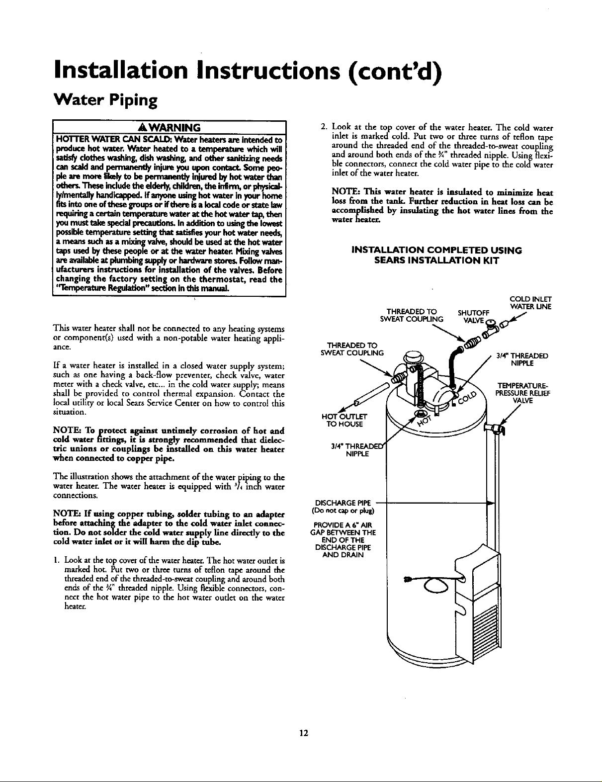
2. Look at the top cover of the water heater. The cold water
inlet is marked-cold. Put two or three turns of teflon tape
around the threaded end of the threaded-tu-sweat coupling
and around bothends of the _Athreaded nipple. Usingflexi-
ble connectors, connect the coldwaterpipe to the coldwater
inlet of the water heater.
NOTE: This water heater is insulated to minimize heat
loss from the tank. Further reduction in heat loss can be
accomplished by insulating the hot water lines from the
water heater.
INSTALLATION COMPLETED USING
SEARS INSTALLATION KIT
COLD INLET
WATER UNE
3/4"THREADED
NIPPLE
TEMPERATURE-
PRESSURERELIEF
VALVE
THREADED TO
SWEAT COUPLING
HOT OUTLET
TO HOUSE
NIPPLE
THREADED TO SHUTOFF
SWEAT COUPLING VALVE
The illustrationshows the attachmentof the waterpipingto the
water heater.The waterbeater is equipped with 'h inch water
connections,
NOTE: If using copper tubing, solder tubing to an adapter
before etmching the adapter to the cold waterinlet connec-
tion. Do not solder the cold watersupply line directly to the
cold water inlet or it will harm the dip tube.
1. Look at the top cover of the water heater. The hot water oudet is
marked hot. Put two or three turns of teflon tape around the
threaded end of the threaded-to-sweat coupling and around both
ends of the _A threaded nipple. Using flexible connectors, con-
nect the hot water pipe to the hot water outlet on the water
heater.
DISCHARGE PIPE
(Do not cap or plug)
PROVIDE A 6" AIR
GAP BETWEEN THE
END OF THE
DISCHARGE PIPE
AND DRAIN
12
Page 13

Installation Instructions (cont'd)
Temperature-Pressure Relief Valve
A WARNING
At the time of manufacture this water heater wasprovided
with a combination temperature-pressuresrelief valvecertified
by a nationally recognized testing laboratory that maintains
periodic inspectionof productionof listedequipment or mute-
rials, as meeting the requirements for Relief Valves and
Automatic GasShutoffDevicesfor Hot Water SupplySystems,
and the latest edition of ANSI Z21.22 and the code require-
ments of ASME. If replaced, the valvemust meet the require-
mentsof localcedes,but net lessthana combinationtempera-
ture and pressure reliefvalvecertified asmeeting the require-
meritsfor ReliefValvesand Automatic GasShutoffDevicesfor
Hot Water SupplySystems,ANSI Z21.22 by a nationally recog.
nizedtesting laboratory that maintains periodic inspectionof
productionuf list_l equipment or material_
The _lve must be mark_ wi_ a meximum set pressuronot
to exceed the marked hydrostatic working pressureof the
water heater (150 IbsJsq.in.) and a dischargecapacitynet less
than the water heater input rate as shownonthe modelrating
plate. (Electric heaters • watts divided by 1000x 3415 equal
BTU/Hr. rate.)
Your localjurisdictionalauthority,whilemandatingthe useofa
temperature-pressurerelief valvecomplyingwith ANSI 7.21.22
and ASME, may require a valve model differentfrom the one
furnishedwiththe water heater.
Compliancewith suchIoc_ requirements must be satisfiedby
the installeror end userof the water heater with a locallypre-
scribedtemperaturo-prossuro reliefwdve instadl_din the desig-
nutedopeningin the water heater in place of the factoryfur-
nishedvalve.
For safeoperationof the water heater,the relief valvemustno_
be removedfrom it'sdesignatedopeningor plugged.
The temperature-pressure reliefvalvemustbe installeddirectly
intothe fittingef thewater hexterdesignatedfer the reliefvalve.
Positionthe valvedownwardand providetubingsothat anydis-
chargewill exit only within 6 inchesabove,or at anydistance
below the structuralfloor.Be certain that no contact ismade
with anyliveelectricalpart. The dischargeopeningmust not be
blockedor reducedin sizeunder anycircumstances.Excessive
length,over30 feet, or useof more than four elbowscancause
restrictionand reducethe dischargecapacityoftbe valve.
No wive or other obstructionisto be placedbetween the relief
valveandthe tank. Do net connecttubingdirectlyto discharge
drainunlessa 6" air gapisprovided.To preventbodilyinjury,haz-
ardto life, or property damage,the reliefvalvemust beallowed
to dischargewater inquantitiesshouldcircumstancesdemand.If
the dischargepipeisnot connectedto a drain or other suitable
means,the water flowmay causepropertydamage.
The DischargePipe:
Must net be smaller in sizethan the outlet pipe size of the
valve,or haveanyreducingcouplingsor other restrictions.
Mustnot be pluggedorblocked.
Mustbeof materiallistedfor hot water distribution.
Must be installedso as to allow complete drainageof both
the temperature-pressure relief valve, and the discharge
pipe.
Mustterminate at an adequatedrain.
Mustnet haveany valvebetweenthe relief valveand tank.
AWARNING
The temperature-pressure relief valve must be manually
operotod at least once a ye_ Caution shouldbe taken to
ensurethat (I) no one is in frant of or around the oudet of
the temperature-pressure reliefvalve dischargeline, and (2)
the water manually discharged will not cause any bodily
injury or property damage because the water may be
extremely hot.
If after manually operating the valve, it failsto completely
reset and continuesto release water, immediately dose the
cold water inlet to the water heater, follow the draining
instructions, and replace the temperature-pressure relief
valvewlth a new one.
TEMPERATURE-PRESSURE
RELIEF VALVE
HOT
/
DISCHARGEPiPE
PROVIDE A 6" AIR
GAP BETWEEN THE
END OF THE
DISCHARGE PIPE
AND DRAIN
plug)
RELIEFVALVEOPENING
Atthetimeofmanufacture,thiswaterheaterv_sprovidedwithacombinationter_
peratum-pressurereliefvabelistedascomplyingwiththestandardforreliefvalvesand
automaticipsthut-offdevtce_for hotwater supply systems.ANSI;[21.22.Forsafe
operationof_ewaterheater,therelief_ mustnotberemovedfromitsdesignated
pointofinstadationor plul_ed,
Yourlocaliuri_ctional authority,while mandating theuseofatemperature-pressure
relief_ahecomplyingwithANSI7.21.22andASME.mayrequireavalvem_eldilferem
fromtheonefurnishedwiththewaterheart
Compliancewithsuchlocalrequirementsmustbesati_ndbytheinstallerorenduser
ofthewaterbeaterwithaIc_al;yprescribedtemperature-pressurereliefvalveinstalled
intheda_ignatedopeninginthewaterheater
Seemanualheading-'_Temporamre-Pressure ReliefValves"forinstallationandmainte-
nanceofreliefvalve,dischargeline,andothersafetyprecautions.
13
Page 14

Installation Instructions (cont'd)
Filling the Water Heater
You must provide all wiring of the proper size outside of the
A CAUTION
Never usethis water heater unlessit iscompletely filed with
wator.To prevent damage te the tank, the tonk must be filled
with water. Water must flow from the hot water faucet
beforeturn ng"ON ' gasto thewater _
To fill the water heater with water:
Close the water heater drain valve by turning the handle to
the right (clockwise). The drain valve is on the lower front of
the water heater.
Open the cold water supply valve to the water heater.
NOTE: The cold water supply valve must be left open
when the water heater is in use.
To insure complete filling of the tank, allow air to exit by
opening the nearest hot water faucet. Allow water to run
until a constant flow is obtained. This will let air out of the
water heater and the piping.
Check all new water piping for leaks. Repair as needed.
Wiring
USE WITH POWER CORD
water heater. You must obey local codes and electric company
requirements when you install this wiring.
If you are not familiar with electric codes and practices, or if you
have any doubt, even the slightest doubt, in your ability to con-
nect the wiring to this water heater, obtain the service of acom-
petent electrician or contact your local electric utility.
A WARNING
WATER HEATERS EQUIPPED FOR ONE TYPE VOLTAGE
ONLY:Thiswater heateris equippedfor 110/120voltsonly.DO
NOT USE THIS WATER HEATER WITH ANY VOLTAGE
OTHER THAN THE ONE SHOWN ABOVE. Failureto usethe
correctvoltagecancauseproblemswhichcanresultinDEATH,
SERIOUS BODILY INJURY OR PROPERTY DAMAGE. If you
haveanyquestionsor doubtsconsultyourelectriccompany.
A CAUTION
If wiring from the fuse box or circuit breaker box was alu-
minum for the old water heater, replace it with copper wire.
If you wish to reuse the existing aluminum wire, have the
connectionat the water heater made by a competent elec-
trician. Contact a localelectrical contractor and/or the local
electric utility.
The water heater comes equipped with a 5 foot power cord
which can be used to connect to a 110/120 volt power source if,
(1) local codes allow, and (2) there is a three prong receptacle
available.
N\
\\
\\
\\
\\
x\
\\
\\
\\
\\
\\
\\
\\
\\
\\
You must provide all wiring, (1) to a receptacle or, (2) between
the water heater and junction box when the power cord is not
used.
5' MAXIMUM
A WARNING
Donotuseanextensioncord.Ifthereisnotasuitablerecepta-
cleand/orlocalcodesprohibituseofapowercord,fieldwiring
mustbeprovided.
USE WITHOUT POWER CORD
If power cord cannot be used, then follow these wiring instruc-
tions.
1. Provide a way to easily shut off the electric power when work-
ing on the water heater. This could be with a circuit breaker
or fuse block in the entrance box or a separate disconnect
switch.
2. Install and connect a circuit directly from the main fuseor
circuit breaker box. This circuit must be the right size and
have its own fuse or circuit breaker.
GROUND SCREW
14
Page 15

Installation Instructions (cont'd)
USE WITHOUT POWER CORD (cont'd)
3. A standard ½" conduit opening has been made in the water
heater junction box for the conduit connection.
4. Use wire nuts and connect the power supply wiring to the
w res inside the water heater's junction box.
5. The water heater must be electrically _grounded" by the
installer. A green ground screw has been provided on the
WIRING DIAGRAM
SW_A4,
_aj_ NO '
I_TO_ _ I_V
O
SWTT_
_Lrmm.
ater heaters _unctlon box. Connect ground wire to th s
location. For complete grounding details and all allowable
exceptions, refer to local codes or in the absence of local
codes, with the latest edition of the National Electrical Code,
ANSI/NFPA 70.
6. Replace the wiring junction cover using the screw
provided.
LtmT_
I
[_
[
p_ss_qE
[
Venting
AWARNING ]
Toinsureproper ventingofthis gas-firedwater heater,the €or- ]
rect vent pipe diameter must be utilized. Any additions of]
other gas appliances on vent with this water heater will
adverselyaffectthe operation ofthe water heater.
The combu.stion and ventilat on a r flow must not be obstructed.
A WARNING [
Thewaterheaterwithdrafthoodinstalledmustbeproperly[
ventedto a chimneywhichterminatesoutdoor_Neveroper-I
atethe_ heat_"unle_itisventedtotheoutdonrsandhasI
adequateairsupplyto avoidrisksof improperoperation,explo-
sionorasphyxiation. I
_i'WARNING I
Ob_ructedordeterioratedve_systemsmaypr--_entaserousI
healthrisk or asphyx_on. I
AWARNING 3" diameter
PVC schedule 40 pipe and must slope upward
The vent pipe from the water heater must be I/4 nch per
near foot.
All vent gases must be completely vented to the outdoors of the
structure (dwelling).
AWARNING I
Failuretohaverequi_l clearancesbetweenwaterheaterand
combustiblemateHaiwillresultn atimhazard.
15
Page 16

Installation Instructions (cont'd)
Venting (cont'd)
VENTING SYSTEM EXAMPLE INSTALLATIONS
Be surevent pipeis properly connectedto p_vent escapeof
dangerousfluegaseswh ch couldcausedeadlyasphyxiation.
•,WARNING r
_kWARNING
Chemical vapor corrosion of the flue and vent system may
occur if air for combustioncontainscertain chemicalvapors.
Spray canpropellants, cleaningsolvents,refrigerator and air
conditioner refrigerants, swimming pool chemicals, calcium
and sodiumchloride, waxes,bleach,and processchemicalsare
typicalcompoundswhichare pote_ally corrosive.
3" PVC SCHEDULE 40 VENT PIPING
Supplied in the carton with the water heater are:
1. A 3" PVC Schedule 40-45 ° vent cap with wire screen.
2. A 3" PVC Schedule 40-90 ° street ell; used to connect the
vent pipe to the water heater when the vent pipe is to be
turned horizontally directly off the blower.
3. A 5' section of 3" PVC Schedule 40 pipe (more may be
required and must be supplied locally).
3" PVC SCHEDULE 40
90* ELBOW
FOR ALL MODELS
The vent piping cannot under any circumstances be run down-
hill.
The _nt piping c_mbe installed as follows:
1. No more than 3 elbows can be used.
ELBO'_¢S
VENT CAP
WITH SCREEN
1. The water heater requires its own (separate) venting
system.
2. 3" PVC, ABS or CPVC Schedule 40 piping and fittings are
acceptable materials for the vent system on all 40 gallon
models and 50 gallon 40,000 BTU/HR models.
3, It cannot be connected to existing vent piping or
chimney.
4. It must terminate horizontally to the outdoors.
MAX. 20'
TOTAL VERTICAL AND
rIE;aTt CANNOT EXCEED 35'
I
HA_3
ELBOWS
HIN. RISE V4"
PER FOOT
MIN. RISE I/4"
PER FOOT
TOTAL VERTICAL AND
HORIZONTAL RUNS
CANNOT EXCEED 35'
16
Page 17

Installation Instructions (cont'd)
VENTING SYSTEM EXAMPLE INSTALLATIONS
FOR ALL MODELS (cont'd)
2. Horizontal runs requzrea m n mum ¼ rise per foot.
13"MIN. I 1" MIN. MIN. RISE¼"
3. A vertical run can be no more than 20'.
4. The total vertical and horizontal run cannot exceed 35'.
MAX. 20'
• , , i i .
35' MAX.
16"HIN.
PEP.FOOT
HIN. RISE ¼"
ONE ELBOW PER FOOT
CEMENTING PVC, ABS OR CPVC PIPE AND FITTINGS
Read and observe all safety information printed on primer,
cleaner, and cement containers.
DANGER
PHmer, cleaner, and cements are extremely flammable.
They are harmful or fatal if swallowed. The vapors are
harmful. They may irritate eyes and skin and can he
absorbed through the skin.
PRECAUTIONS
Always store primers, cleaner, and cements in cool, dry,
well ventilated places. Do not store them near heat,
sparks, or flames. Keep containers closed. Use them in
well ventilated areas. Wear impervious clothing while
handling. Do not smoke, eat, or drink while handling.
Wash thoroughly after handling and before eating. Wear
eye protection when handling. If swallowed, drink water,
do not induce vomiting, and call a physician or poison
control center immediately. If inhaled, get fresh air and
seek medical attention if ill feelings persist. In case of
eye and skin contact, immediately flush with plenty of
water for 15 minutes and seek medical attention if irri-
tation persists. KEEP OUT OR REACH OF CHILDREN.
All primers, cleaners, and cements must meet all local codes and
applicable standards of the American Society For Testing
Materials Standards.
Before using primers, cleaners, and cements, stir or shake, mak-
ing sure contents are liquid. Do not use if found to be lumpy or
jelly-like. --
T
I I
TOTAL VEffFICAL AND
HORIZONTAL RUNS
CANNOT EXCEED 35'
MIN. RISE ¼"
PER FOOT
TOTAL VERTICAL AND
HORIZONTAL RUNS
CANNOT EXCEED 351
1. Cut pipe ends squarely removing all burrs and dirt.
2. Dry fit pipe and fittings to be connected for proper fit.
3. Clean pipe and fitting with a primer/deaner.
4. Apply a thin coat of cement to fitting, avoiding puddling
inside.
5. Apply a liberal coat of cement to pipe leaving no voids.
6. QUICKLY assemble parts while cement is flui!! If you wait
too long, re-coat pipes.
7. Push pipe completely into socket of fitting, turning as it goes
until it bottoms.
8. Hold p_e and fitting together for 30 seconds. Then carefully
clean orr excess with a cloth. Allow connections a sufficient
time to cure before disturbing.
9. Remember that vent pipes must be adequately and securely
supported.
APPROXIMATE SETTING TIME FOR 2½" TO 4" PIPE
OINTS
MOVEMENT COMPLETE
90°F to 150°F _Ahr. 8 hrs.
50°F to 90°F 1 hr. 15 hrs.
O°Fto 50°F 1¼ hr. 18 hrs.
OF JOINT SET
17
Page 18

Installation Instructions (cont'd)
Venting (cont'd)
CUTTING OPENING THROUGH AN OUTSIDE
WALL AND COLLAR INSTALLATION
After reading themanual and you have determined the location
of the opening in the wall, (using the drawingbelow), cut a 3½
hole through a_ exteriorwall.
NOTE: When determining location of the opening in the
outside wall allow for the ¼" rise per foot that has taken
place in the horizontal run.
C LofFlue .-_.........
40 GAL- 00"
SO GAL- S9'A"
]._
CONNECTING PVC, ABS OR CPVC PIPE VENT TO
BLOWER
1. The manufacturerhas supplied a 3" PVC Schedule 40 street
elbowfor connection to the water heaterwhen t " "
:urmngimme-
diately horizontally off the blower. Place the elbow in the
required direction on the blower and using 3 sheet metal
screws,attach the elbow.
2. If there is to be a vertical runof vent from the blower,the 3"
PVCor ABSpipe must be attached to the blowerusing 3 sheet
metal screws.Additionally,you must sealalljoints using a suit-
ablesiliconesealersuch as GE RTV-103or equivalent.
/
The 3" FVC,ABS or CPVC Schedule40 vent pipe can be run
from the water heater through the wall or from the wall to the
water heater, whichever ismost convenient. The vent pipe must
extenda minimum of 1½ through the exterior wall. Extending
the vent cap as far as possible from the surface of the exterior
wall will help minimize discoloration of the wall in this area
which may be caused by the flue gases.Note that the inside col-
lar must be slipped over the vent piping before locating the pipe
through the wall. Before securing the inside and outside collars
to the wall, use a silicone sealer between pipe and opening to
insure a water and airtight seal.
INSTALLATION SHOWING USEOF PVC, ABS OR
CPVC PIPE
EXTERIOR WALL
_EALEIt
1_ _N,EX_IENSION
THROUGH
EXI'EI_IOR WALL
SCREW
I I
18
Page 19

Installation Instructions (cont'd)
Gas Piping
AWARNING
Make sure the gas supplied is the same type listed on the
model rating plato, The inlet gas pressuremust not exceed
10.5in.water column(2.6kPa) for natural gasor 13in, water
column (3.2kPa) for propane (L.R) gas. The minimum inlet
gaspressurelisted on the model rating plate isfor the pur-
poseof input adjustment.
AWARNING , I
Ifthe gascontrolvalveissubjectedto pressuresexceeding½
I poundpersquareinch(3.SkPa),the damageto the gascon-I
[trel valvecouldresultinafireor explosionfromleakingga_ J
AWARNING ]
If themaingaslinesh_gas appliancesisused_|
elsotorn "off" thegasat each_ianco. Leave_ irasapp,-|
ancesshutoffuntilthewaterheaterinstellationiscomplete./
A gas line of sufficient size must be run to the water heater.
Consult the latest edition of National Fuel Gas Code ANSI
Z223.1,also referredto as NFPA54 and the gascompany concern-
ingpipe size.
Ther_ i_l._t be;
• A readily accessible manual shut off valve in the gas supply line
serving the water heater, and
• A drip leg (sediment trap) ahead of the gas control valve to help
prevent dirt and foreign materials from entering the gas control
Valve.
• A flexible gas connector or a ground joint union between the
shutoff valve and control valve to permit servicing of the unit.
t AWARNING 1
Usepipe joint compoundorteflon tape markedasbeingI
resistantto the actionofpetroleum[Propane(L.R)]gase_
SEDIMENT TRAP
A sediment trap shall be installed as close to the inlet of the
water heater as practical at the time of water heater installation.
The sediment trap shall be either a tee fitting with a capped nip-
ple in the bottom outlet or other device recognized as an effec-
tive sediment trap. Ifa tee fitting is used, it shall be installed in
conformance with one of the methods of installation shown
below.
Connecting the gas piping to the gas control valve of the water
heater can be accomplished by either of the two methods shown.
GAS PIPING WITH
FLEXIBLE CONNECTOR
F1ANI2AL_HU'r OFFVAI_VE _ ;'_ SUPPI-YFIFqNG
GROUND
UNION
FLEX)B_EGAS CONNECTOR
I.ABIEIA_ AS COMPLYING
VVI_ ANSIffTAN[R_DS
LOOp
GAS
CONTROL
VALVE
Be sure to check all the gas piping for leaksbefore lighting the
water heater. Use a soapy watersolution, not a match or open
flame.Rinseoffsoapysolutionand wipe
Standard Modds are for instanadoa up to 3,300 feet above sea
level.
High Altitude Modds are for installation from 3,300 to 5,500
leer above sea level.
Ifa standard model is installed above 3,300 feet or a high altitude
model is installed above 5,500 feet, the input rating must be
reducedat the rate of 4 percent for each 1,000 feet above sea level.
Contact your local Sears Service Center or gas utility for further
informatiorL
AWARNING
The appliance and Its gas connection must be leak tested
beforeplacng the appliance n operation.
AWARNING
• The applianceand its individualshutoffvalvemust be discon-
nectedfrom the gassupplypiping s/stem duringany pressure
testing of the gassystem at test pressuresin excessof I/2
•poundper square inch(3.5kPa).
The appliancemustbe isolatedfrom the gassupplypipingsys-
tem by €_ng its iedhddu_ manual shuto_ valve during any
pressuretestingof the gassupply pipingsystemat test pres-
suresequalor lessthan I/2 poundper square inch(3.SkPa).
GAS PIPING WITH ALL BLACK IRON
PIPE TO GAS CONTROL
GROUND_NT
UNION
3_ FtlN"
Contaminants in the gaslinesmay causeimpmpor operation
of the gascontrol valve that may result in fire or explosion.
Before at_'mchingthe gaslinebe sure that allgas pipe isclean
on the inside.To trap any dirt or foreignmaterial in the gas
supply line, a drip leg (sometimes called a sediment trap)
must be incorporated in the piping. The drip leg must be
readilyaccessible. Installin accordancewith the "Gas Piping_'
section. Referto the latest edition of the National Fuel Gas
Code, ANSI Z223.1,alsoreferred to asNFPA 54.
BLACK F1PE
C_
AWARNING
19
Page 20

Installation Instructions (cont'd)
Installation Checklist
BEFORE LIGHTING THE PILOT:
• Check the gas lines for leaks.
a. Use a soapy water solution. DO NOT test for gas leaks
usinga match or open flame.
b. Brush the soapy water solution on all gas pipes, joints and
fittings.
c. Check for bubbling soap. This means you have a leak,
Turn"OFF gas and make the necessary repairs.
d. Recheck for leaks,
e. PJ.nse off soapy solution atld wipe dry.
• Is the new temperature-pressure relief ,,v_lveproperly installed
and piped to an adequate drain? See Temperature-Pressure
Relief Valve" section,
• Are the cold and hot water lines connected to the water
heater correctly? See _Water Piping _ instructions in the
°Installing the New WaterHeater"section.
• ISthe water heater comp|etely filled with water? See "Filling"
instructions in the "Installing the New Water Heater" sec-
tion.
• Will a water leak damage anything? See the "Locating the
New Water Heater" section.
• Is there proper clearance between _e water heater and any-
thing that might catch fire? See the Locating the New water
Heater" section.
i
VENT PIPE TO
OUTDOORS
SHUTOFF ,_
VALVE
COLD
TEMPERATURE-
PRESSUREREUEF
VALVE
(Do not cap or plug}
• Do you have adequate ventilation so that the water heater
will operate properly? See "Combustion Air and Ventilation"
in the "Locating the New Water Heater" section.
• Is the draft hood vent piping properly secured? See "Venting"
instructions in the "Installing the New Water Heater" sec-
tion,
• Is there proper clearance between the vent pipe and anything
that might catch on fire? See "Venting_ instructions in the
"Installing the New Water Heater" section.
• Is the ventpipe properly sloped and does the vent terminate
outdoors? See "Venting" instructions in the "Installing the
New Water Heater" section.
• Do you need to call your gas company to check the gas pipe
and its hookup?
(Sedimenttrap)
"a_n_a_ M°wal w_llm _111"_ NUtI_R C_,_CnY @
I I wA.-
_uk _W-
WVT _ Im_. NUla_q
_A_ _PRE I4W_
'- I I ]
MODEL RATING PLATE
2O
Page 21

Operating Instructions
This water heater is equipped with an electrically operated vent-
ing system and a standing pilot. For the burner to come on, the
water heater thermostat must call for heat. Then the system will
begin sequencing, each section proving itself before gas is
allowed to flow to the burner.
BEFORE THE WATER HEATER WILL OPERATE:
BLOWER MOTOR
1. The control system must be connected to a 110/120 volt
power supply. The control system has an overall rating of 2
amps. The water heater must be securely and adequately
grounded in accordance with local codes and with the latest
edition of the National Electrical Code ANSI/NFPA 70.
2. The ON/OFF toggle switch, located on the control box
above the thermostat must be in the "ON" position for the
electrical control system to operate allowing the gas portion
to operate (ignite burner).
3. The pilot must be lit. See Lighting instructions on page 23
of this manual or located adjacent to the thermostat on the
water heater.
4. The gas control knob located on the thermostat must be
turned to the "ON" position for the gas to be able to flow.
5. The venting manual reset switch must be in the closed posi-
tion. See "Venting Manual Reset Switch" in the "For Your
Information Section".
6. There is a non-resettable hi-limit switch in the thermostat,
which must be good (dosed) for the thermostat to be oper-
ated. See "High Tempera, ture Shut Off System" in the "For
Your Information Section .
OPERATION
When the thermostat calls for heat, gas is allowed to flow to a
(Normally open) pressure switch dosing it. An electrical circuit
is then made to the blower, turning it on. The indicator light
located on the control box will come on. When the blower has
achieved sufficient venting, the air pressure switch will close and
the indicator light will go off. A 120 volt circuit will be com-
pleted through the venting manual reset switch and on to the
120 volt gas valve located just below the thermostat. The 120
volt _._ valve will open allowing gas to flow to the burner. The
standing pilot will establish a main burner flame.
VENTING MANUAL
RESETSWITCH
DRAFT HOOD
GAS CONTROL
KNOB
GAS THERMOSTAT
AIR PRESSURE
ON/OFF SWITCH
LIGHT
120V GAS VALVE
21
Page 22

Operating Instructions
Lighting
AWARNING
BEFORE LIGHTING [PROPANE (L.P,) GAS WATER
HEATERS]:Propane(LR) gasis heavierthan air,Shouldthere
be a leak in the system,the gas will settle near the ground.
Basements, crawl spaces,skirted areas under mobile homes
(evenwhenventilated),closetsandareasbelow groundI_el will
serve as pockets for the accumulation of this gas. Before
attemptingto lightor relight the water heater'spilot or turning
ona nearbyelectricallight switch,be absolutelysumthere isno
accumulatodgasinthe area.Searchfor odor ofgasbysnimng at
groundlevel in the vicinityofthe appliance.If odor isdetected,
followstepsindicatedat "For Your Safety" on the coverpageof
thismanualthen leavethe premise_
Lighting and operating instructions are located on front of the
water heater, above or to one side of the gascontrol valve.
AWARNING
AN ODORANT ISADDED TO THE GAS USED
BY THIS WATER HEATER.
FOR YOUR SAFETY
IF YOU SHELL GA_
• Do not try to lightanyappliance.
• Do not touch anyelectrical switch;do not useanyphone in
your building.
ImmedL_l_y call yourgassupplier from aneJshbor'sphone.
Figure 9 I
IFigure I0]
If you cannot reach your gas supplier, callthe fire depart-
ment,
A WARNING
DO NOT force the gascontrot knob. Use only your hand _)
pushit down to lightthe pilot, or to turn it to "ON", "OFF"
or "PILOT". Never usea tool suchas a lever,ranch or pli-
ers. Do not hit or damage the Imob.A damaged knob mz/
result in an explosionand seriousinjury.If you haveproblem
toming the Imob,callthe gassupplierimmndiaCely.
Figure I I I
INNER DOOR
OUTER DOOR
Figure 12]
22
Page 23

Operating Instructions (cont'd)
Lighting label on the water heater as it appears above the thermostat
m
A.Thisappliancehasa pilotwhichmustbelightedby
hand.Whenlightingthepilot,followtheseinstructions
exactly.
B.BEFORELIGHTINGsmallallaroundtheappliancearea
forgas.Besureto smellnextto the floor because
somegasisheavierthanairandwillsettleonthefloor.
WHATTODOIFYOUSMELLGAS
• Donottrytolightanyappliance.
• Donot touchanyelectricswitch;donotuseany
• Immediatelycallyourgassupplierfromaneighbor's
FOR YOUR SAFETY READ BEFORE LIGHTING
WARNING
If you do not follow these instructions exactly a fire or explosion
may result causing property damage, personal injury or loss of life.
phoneinyourbuilding.
phone.Followthegassupplier'sinstructions.
LIGHTING INSTRUCTIONS
1. STOP!Readthesafetyinformationaboveonthislabel.
2. "ltJrnON/OFFswitchoncontrolboxto"OFF".
3. Removeouter door coveringgasthermostatand
burnerassembly.{Figure12,Page22)
4. Set the thermostatto lowestsetting
by turning the watertemperaturedial
clockwise,(F-_) toits lowesttempera-
ture setting (with arrow on dial) as
shown.DO NOT FORCE. (Figure9,
Page22) ,_
5. Turngascontrolknobcleckwise'r_,r* to "OFF"pesi-
tion.Knobcannotbeturnedfrom"PILOT"to "OFF"
unlessknobisdepressedslightly.DONOT FORCE.
6. Waitfive(5) minutestoclearoutanygas.If youthen
smallgas,STOP!Follow"B"In thesafetyinformation
aboveonthislabel.Ifyoudon'tsmellgas,go tothe
nextstep.
7. Remove(or open)innerdoorlocatedbelowthegas
controlunit.
8. Findpilot--followmetaltubefromgascontrol.Thepilot
Islocatedontherighthandaideefthebumer.
PtLOT BURNER __THERMOCOUPLE
9. If you don't smellgas,turn knobon gas control
counter-clockwise
Page22)
{,=(_, to"PILOT"position.(Flgurog,
@
• if youcannotreachyourgassupplier,callthe fire
department.
C. Useonlyyourhandtopushinorturnthegascontrol
knob.Neverusetools.Iftheknobwillnotpushinof
turnbyhand,don'ttrytorepairit,cella qualifiedner.
vicetechnician.Forceor attemptedrepairmayresull
inafireorexplosion.
D.Donotusethis applianceif anyparthasbeenunder
water.Immediatelycalle qualifiedservicetechnician
toinspecttheapplianceandtoreplaceanypartofthe
controlsystemandanygascontrolwhichhasbeen
underwater.
10.Pushin controlknoball the wayand holddown.
Immediatelylightthe pilotwitha match.Continue
to hold controlknobin for aboutone (1) minute
afterthe pilot is lit. Releaseknoband it will pop
back up. Pilot shouldremain lit. If It goes out,
repeatsteps5through10.
• If knob doesnot pop up when released,stop
andimmediatelycoil yourservicetechnicianor
gassupplier.
• If the pilot will notstay lit afterseveraltries,
depressandturn the gas controlknobclock-
wise _P_I to "OFF"andcallyourservicetech-
nicianorgassupplier.(Figure9,Page22)
11.Replaceinnerdoor.(Figure12,Page22)
12.Atarmslengthaway,turngas controlknobcounter-
clockwise_0 tothefull"ON"position.WARNING
Do not use-_as control knob to regulate gas
flew. (Flguro11,Page22)
13.At armslengthaway,eatthe thermostattodesired
setting.Themark(T) HOTIndicativeofapproximate
120°Fispreferredstartingpoint.Somelocallawsmay
requirea lower startingpoint. If hotter wateris
desired,seeinstructionmanualand"wamlng"below.
14.Replacetheouterdoor.(Figure12,Page22)
15."rumON/OFFswitchoncontrolboxto"ON".
i Hotterwaterincreasestheriskofscaldinjury.Beforechangingtemperaturesetting seeinstructionmanual.
WARNING I
TO TURN OFF GAS TO APPLIANCE
1. TurnON/OFFswitchoncontrolboxto"OFF".
2. Removeouter door coveringgasthermostatand
burnerassembly.(Figure12,Page22) _L
3. Set the thermostat to lowestsetting
by turning the water temperature j_i_
dial clockwise (("-_,) to its lowest i_r_-_=dal
temperaturesetting(witharrowon dial)
asshown.DONOT FORCE. _
4. "rumgascontrolknobclockwise'_'-,,""to"OFF"posi-
tion.Knobcannotbeturnedfrom"PILOT"to"OFF"
unlessknobisdepressedslightly.DONOTFORCE.
(Figure9,Page22)
5. Replaceouterdoor.(Figure12,Page22)
23
Page 24

Operating Instructions (cont'd)
Temperature Regulation
Due to the nature of the typical gas water heater, the water tem-
_oerature in certain situations may vary up to 30*F higher or
wet at the point of use such as, bathtubs, showers, sink, etc.
This means that when the temperature adjustment dial is set at
the mark approximating 120" F,the actual water temperature at
any hot water tap could-be as high as 150OF or as low as 90*E
Any water heater's intended purpose is to heat water. Hot water
is needed for cleaning (bodies, dishes, clothing). Hot water will
present a scald hazard. Depending on the time element, and the
people involved (normaladults, children, toddlers, elderly,
infirm, etc.) scalding may occur at different temperatures.
AWARNING
HOI-I'ER WATER CAN SCALD:Water heatorsam imended_
producehot watt. Water heated to a temperature whichwill
satisfyclotheswashln_dishwashinl_andother sanitizingneeds
c_ scakland_ injure youupeocoutuct,Some peo-
pleare morelikelyto be permanendy injuredby hot water than
others.TheseincJudetheelderly,children,the infirm,or physical-
lylmentelly ban&capped, If anyone using hot water in your home
fitsIntoone ofthasegruupsor ifthere isa localcodeor state law
requiringa certaintemperatere water at the hot water tap,then
ou musttake specialpmcau_om. Inadditionto usingthe lowest
mssibietemperature settingthat salariesyour hot water need_
meanssuchas a mixingvalve,shouldbe usedat the hot water
tapsusedbythesepeopleor at the water heater.Mixingvalves
are availableat plumbingsupplyor hardwarestore_ Followman.
ufacturers instructions for installation of the valves. Before
changing the factory sett ng on the thermostat, read the
'q'emperatureRegulation"sectioninthis manual.
Turn the water temperature dial dockwise___'x,) to decrease
the temperature, or counterdockwise (€"-_"_) to increase the
temperature.
• HOT-Is a thermostat setting of approximately 1200F,
which will supply hot water at the most economi-
cal temperatures. The temperature adjustment
knob can be turned lower than "HOT" if desired.
A- Is a thermostat setting of approximately 130°E
B- Is a thermostat setting of approxitoately 140°E
C- Is a thermostat setting of apprc.xitoately 15O°F.
VERY HOT- Is a thermostat setting of 160°E It is recommend-
ed that the dial he set lower wherever possible.
AWARNING
NeveraJlowsmaJlchildrento ucea hotwatertap,or to draw
theirownbathwater,Neverleaveachildor handicappedper-
sonunattendedina bathtuborshower.
The thermostat of this water heater has been factory set at its
lowest position, to reduce the risk of scald injury. It is adjustable
and must be reset to the desired temperature setting. The mark
(V) HOT indicative of approximately 120*F is the preferred
starting point. Some states have a requirement for a lower set-
ting. ffyou need hotter water, follow directions for temperature
adjustment, but beware of the warnings in this section.
NOTE: Water temperature range of 120°-1400F recom-
me_uled by most disltwasher manufuctnrers,
•,WARNING ]
Shouldoverheatingoccuror the gassupplyfailto shutoff,I
turn 'OFF themant_gascontroivaJvetotheappllance.
24
Page 25

Service and Adjustment
Tank (Sediment) Cleaning
Sediment build-up on the tank bottom may create v_ing amounts of
noise, and if left in the tank will cause premature tank failure. In some
water areas,you may not be able to drain all sediment deposits by
simply draining the tank. In these cases Mag Erad (part no. 23600)
can be used to help remove the sediment deposits. This may be
ordered from the Sears Service Center. For ordering, refer to the
_Repair Parts" section.
Venting System Inspection
At least once a year a visual inspection should be made of the
venting system. You should look for:
• Obstructions which could cause improper venting. The com-
bustion and ventilation air flow must not be obstructed.
Damage or deterioration which could cause improper venting
i or leakage of combustion products.
Rusted flakes around top of water heater.
AWARNING
Chemical vapor corrosion of the flue and vent system may
occurif air for combustioncontainscertain chemicalvapom
Spray can propellants,cleaningselvan_, refrigerator and air
conditioner refrigerants, swimming pool chemicals, calcium
andsodiumchloride,waxes,bleach,and processchemicalsa_
typicalcompoundswhichare poter_dailycorrosive.
&WARNING
Obstructeder deterioratedvantsystemsmay present a serious
healthrisker asphyxlatlon.
Burner Inspection
AWARNING I
Doont usethisapplianceif anyport of Ithasbeenunderwa_. I
Immediatelycalla SearsServiceTechnicianto inspectthe I
applianceand to replacethe gascontrolor any part of the
burnersystemwhlchhasbeenunderwater.
At leastonce a year a visual inspection should be madeof the
main burner andpilot burner. The drawingisfor your reference.
You should check for sooting which is not normal and will
impair proper combustion.
I AWARNING ]
Soot build-up indicate_at requirescorrection |
beforefurther use.Turn "off" gasto water heater and leave|
"off" until repairs are made, becausefailure to correct the|
causeof the sootingcan result in a fire or explosioncausing|
death,seriousbodilyinjury,orpropertydamage.
Burner Cleaning
AWARNING I
Be sure the vent piping is properly connected to prevent I
escape of dangerous flue gesses which could cause deadly
asph_i_o_
A WARNING -_
ff after inspection of the vent _ you found sootingor I
delasrtorellon,something iswrong. Call the Iocaiges utUityto I
correctthe ix.oblem and dean er replacethe flue and ranting I
beforeresumingoperation of the water heater, |
Oiling Instructions
Oil motor every 12 months with 6 drops ofSAE 20 motor oil.
In the event your burner needs cleaning, use thefollowing
instructions:
If inspection of the burner shows that denning is required, turn
the gas control knob clockwise (_"_) to the _OFF" position,
depressing slightly.
NOTE: The knob cannot be turned from "PILOT" to "OFF"
unless knob is depressed slighdy. DO NOT FORCE.
Loose deposits on or mound the burner can be removed by care-
fully using the hose of a vacuum cleaner inserted through the
access door of the water heater. If the burner needs to be removed
for additional deaning, call the Sears Service Center to remove
and dean the burner and correct the problem that required the
burner to be cleaned.
25
Page 26

Service and Adjustment (cont'd)
L.P.Gas Control Valve & Burner
Assembly Replacement
Information
AWARNING
PROPANE(L.P.) GAS CONTROL VALVE AN BURNER
ASSEMBLYREPLACEMENTINFORMATION,
ForPropane(L.R)GasModelsOnly:.
Yourwaterheaterisequippedwitha Propane(L.R)gascon-
trol ,¢ai_ an_ a maln burner assem_ ,_da I_ ha_ threeds
forthe followingfittingsand their connections.
The connectionbetweenthe manifold andthe gas i
controlvalve(A to B) are lefthandthreads.
The connectiembetween the main burner ori_e
and the manifold(C to D) are lefthandthreads.
For orderingthese replacement parts, pleaserefer to
the "Repair Parts" sectionof this manual.
Draining
The waterheater should be drained if being shut down during
freezing temperatures. Alsoperiodic draining and cleaning of
sediment from the tank maybe necessary.
Turnthe gascontrol knob to the _OFF" position.
CLOSE the cold water inlet valveto the waterheater.
• OPEN a nearby hot water faucet and leaveopen to allowfor
draining.
• Connect a hose to the drain valveand terminate to an ade-
quate drain.
• OPEN the water heater drainvalveto allowfor tank draining.
NOTE: If the water heater is going to be shut down and
drained for an extended period, the drainvalveshould be
left open with hose connected allowing water to t_.rminate
ta an adequate drain.
• Closethedrain valve.
Follosuinstructions in the "FillingTheWaterHeater"section.
: Followthe lightinginstructionsin the _Lighting section to
restartthe waterheater.
Temperature-Pressure Relief
Valve Operation
The temperature-pressure relief valve must be manually operated
at least once a year.
A%
RELIEF VALVE
DISCHARGE PIPE
Failure to install and maintain a new properly listed tempera-
lure-pressure reliefvalvewill rdeasethe manufacturer from any
claimwhich might result fi'om excessivetemperature orpressure.
AWARNING
if the temperature-pressuro relief valve on the appliance
weepsor dischargesperiodically,this may be due to thermal
expansion. Your water heater may have a check valve
installed in the water line or a water meter with a check
valve. Consultthe SearsService Center for further infurma-
tlan. Oo not plugthe temperature-pressero rolief _lve.
' AWARNING
i
When checkingthe temperature-pressure reliefvalve opera-
tio_, make sure that (i) no one is infront of or arouod the
out_t ofthe temperature-pressurereliefvalvedischargeline,
and (2) that the water manuallydischargedwill not causeany
propertydamage becausethe water maybe extromety hot.
If after manually operating the valve, it fails to completely
and cantiw,|e_ to _e_e water, _m_ close the
cold water inlet to the water heater, follow the draining
instructions, and replace the temperature-pressure relief
valvewith a new one.
26
Page 27

Service and Adjustment (cont'd)
Drain Valve Washer
Replacement
NOTE: For replacement, use a 17A2"x ly.,, x _" thick washer
available at your nearest hardware store. For ordering replace-
merit washers, refer to the "Repair Parts" section.
Turn "OFF" gas supply to water heater.
Follow "Draining" instructions.
Turning counter clockwise, remove the hex cap below the
screw handle.
Remove the washer and put the new one in place.
Screw the handle and cap assembly back into the drain valve
and retighten using a wrench. DO NOT OVER TIGHTENs,
Follow instructions in the Filling The Water Heater
section.
Check for leaks.
Follow the lighting instructions in the _Lighting _ section to
restart the water heater.
Housekeeping
Vacuum around base of water heater for dust, dirt, and lint on a
regular basis.
Combustible materials such as dothing, cleaning materials, or
flammable liquids, etc. must not be placed against or adjacent to
the water heater.
To insure sumcient ventilation and combustion air supply, prop-
er clearances from the water heater must be maintained at all
times.
Service
Before calling for repair service, read the Start Up Conditions
and Operational Conditions found in the Troubleshooting
Guide of this manual.
If a condition persists or you are uncertain about the operation
of the water heater, let a qualified person check it out.
Contact SEARS Repair Services at 1-800-4-MY-HOME
(1-800-469-4663).
27
Page 28

Troubleshooting Guide
Start Up Conditions
THERMAL EXPANSION
Water supply systems may, because of such events as high line
pressure, frequent cut-offs, the effects of water hammer among
others, have installed devices such as pressure reducing valves,
check valves, back flow preventers, etc...to control these typgs of
_roblems. When these devices are not equip_sed with an internal
oy-pass, and no other measures are taken, me devices cause the
water system to be dosed. As water is heated, it expands (ther-
mal expansion) and closed systems do not allow for the expan-
sion of heated water.
The water within the water heater tank expands as it is heated and
increases the pressure of the water system. If the relieving point of
the water heater s temperature-pressure rel'ef valve is reached, the
valve will relieve the excess pressure. The temperature-pressure
reed valve is not intended for the €o_st_nt relief of thermal
expansion. This is an unacceptable condition and must be cor-
rected.
It is recommended that any devices installed which could create a
closed system have a by-pass and/or the system have an expan-
sion tank to relieve the pressure built by thermal expansion.
Thermal expansion taaks are available from Sears stores and
through the Sears Service Centers. Contact the local plumbing
inspector, water supplier and/or the Sears Service Center for
assistance in controlling these situations.
Thermal Expansion Tank Specifications
Model
Number
153.331020
153.331050
2
5
Dimettsiom in Inches
Diameter Length
8 inches 12_ inches
11 inches 14_ inches
Pipe Fittir_g
On Tank
_" Male
_" Male
COLD
WATERHF_TER
COLD WATER
INLETFITTING
HOT COLD
WATER HEATER (3)
COLDWA'I--_ pRESSURE
INLET FrI'rlNG REDUCING
VALVEWITH
BY-PASS
WATER
SHUTOFF
RECOHFtEHDED IHISTALLATIOH
(V_nCAL MOUNT._)
P,.OOR,CEtUNG
lOST,ETC.
STRAPPING
O)
PRESSURE
REDUCING INLET COLD
VALVE WITH WATER
BY4PASS SHUTOFF
Expansion Tank Sizing Chart
Inlet*
Water
Pressure 30 40 50 66 82
Ex_,_onn--o; 40psi 2 2 2 5 5
Capacity 50psi 2 2 2 5 5
Needed 60psi 2 2 5 5 5
70psi 2 2 5 5 5
80psi 2 5 5 5 5
*Highest recorded inlet water pressure in a 24 hour period or
regulated water pressure.
NOTE: Expansion tanks are pre-charged with a 40 psi air
charge. If ti_e inlet water pressure is higher than 40 psi, the
expansion tanks a'r pressure must be adjusted to match that
pressure, but must not be higher than 80 psi.
Water Heater Capacity (Gallons)
ALTERNATE RECOHMENDED
INSTALLATION
(HORIZONTAL MOUNTING)
STRANGE SOUNDS
Possible noises due to expansion and contraction of some metal
parts during periods of heat-up and cool-down do not represent
harmful or dangerous conditions.
Condensation causes sizzling and popping with the burner area
during heating and coolin_ periods and should be considered
normal. See "Condensation section.
28
Page 29

Troubleshooting Guide (cont'd)
CONDENSATION
Whenever the water heater is filled with cold water, a certain
amount of condensation will form while the burner is on. A
water heater may appear to be leakingwhen in fact the water is
condensation. This usually happens when:
• When a new water heater is filled with cold water for the
first time.
• When gas burns and water vapor isproduced in water
heaters, particularly high elTlciency models where flue tem-
peratures are lower.
• When you use large amounts of hot water in a short time
and the refill water is very cold.
Moisture from the products of combustion condense on the
cooler tank surfaces and form drops of water which may fall
onto the burner or other hot surfaces to produce a _sizzling" or
"frying"noise.
Excessivecondensation can cause piloicoutage due to waterrun-
ning down the flue tube onto the main burner and putting out
the pilot.
Becauseof the suddenness and amount of water, condensation
watermay be diagnosedas a "tank leak".After the water in the
tank warms up (about 1-2 hours), the condition should disap-
pear.
Do not assume the water heater is leaking until there has been
enough time for the water in the tank to warm up.
An undersized water heater will cause more condensation. The
water heater must be sized_roperly to meet the family's demands
for hot water including dishwashers, washing machines and
shower heads.
Excessive condensation may be noticed during the winter and
early spring months when incoming water temperatures are at
their lowest.
Good venting is essential for agas firedwater heater to operate
properly as well as to carry away products of combustion and
water vapor.
SMOKE/ODOR
It is not uncommon to experience a small amount of smoke and
odor during the initial start-up. This is due to burning off of oil
from metal parts, and will disappear in a short while.
Operational Conditions
SMELLY WATER
In each glasslined water heater there is installed at least one
anode rod (see parts section) for corrosion protection of the
tank. Certain water conditions will cause a reaction between this
rod and the water. The most common complaint associated with
the anode rod is one ofa *rotten egg smell". This odor is derived
from hydrogen sulfide gas dissolved in the water. The smell is
the result of four factors which must all be present for the odor
to develop:
a. a concentration of sulfate in the supply water.
b. little or no dissolved oxygen in the water.
c. a sulfate reducing bacteria within the water heater. (This
harmless bacteria is non-toxic to humans.)
d. an excess of active hydrogen in the tank. This is caused by
the corrosion protective action of the anode.
Smelly water may be eliminated or reduced in some water heater
models by replacing the anode(s) with one of less active material,
and then chlorinating the water heater tank and all hot water
lines. Contact Sears Service for further information concerning
an Anode Replacement Kit #9001453 and this Chlorination
Treatment.
If the smelly water persists after the anode replacement and chlo-
rination treatment, we can only suggest that continuous chlori-
nation and filtering conditioning equipment be considered to
eliminate the water problem.
Do not remove the anode leaving the tank unprotected. By
doing so, all warrantyon the waterheater tank is voided.
&WARNING
HOTrER WATER CAN SCAL_. Water heatersare intendedto
imxha:e hot water. Water heated to a _nporatum which will
satisfydothes washing,dishwashing, and other sanitizing needs
canscaldand permanentlyinjureyou uponcontact. Some pee.
pieare moreh_ely to be permonentlyinjuredby hot wa_erthan
ot_,rs. Theseinclude the elderly,children,the infirm,or I_
ly/montallyhandicapped.Ifanyoneusinghotwater inyour home
Etsintoone ofthese greupsor ifthere isa localcodeor sterelaw
requiring a certain temperaturewater at the hot water Cap,thon
youmusttakespoclalprecaudonLIn additionto usingthe inwest
possibletemperature settingthat satisfiesyour hotwater needs,
a meam suchasa mixingvalve,shouldbe usedat the hot water
tapsusedbythese poople or at the water heater. M_xingvalvesI
areavailable at plumbingmpply or hardwarestore_Followman-
ufacturers instructions for installation of the valves. Before
changingthe factory setting on the thermostat, read the
'q'emporatureRegulation"sectioninthismanual.
29
Page 30

Troubleshooting Guide (cont'd)
Operational Conditions (cont'd)
"AIR" IN HOT WATER FAUCETS
_,WARNING
HYDROGEN GAS: Hydrogen gas can be produced in a hot
water systomthat hasnot bean usedfor a longpe_od of time
(generally two weeks or more). Hydrogen gas is extremely
flammable and explosive.To prevent the possibilityof injury
under these conditions,we recommend the hot water faucet
be opened for severalminutesat the kitcben sinkbefore any
electricalapplianceswhich are connectedto the hotwater sys-
tom are used(suchas a dishwasheror washingmachine). If
hydrogengas is present, there will probably be an unusual
soundsimilarto air escapingthrough the pipe as the hot water
faucet is opened, There must be no smokingor open flame
neart_ f_ at the _w Kis opan.
HIGH TEMPERATURE SHUT OFF SYSTEM
This water heater is equipped with an automatic gas shut offsys-
tem. The high temperature shut off is built into the gas control
valve. This system shuts off the gas supply to the water heater
burners when high water temperatures are present. It is non-
resettable. If the high temperature shut offactivates, the gas con-
trol valve must be replaced. If this were to occur, turn _OFF" the
entire gas supply to the water heater. Contact the Sears Service
Center.
WATER IS TOO HOT
1. The temperature adjustment dial may be set too high. See the
_Temperature .Adiustment" section.
NOTE: Aperiod of time is necessary after an adjustment has
been made for the water temperature to reach the new tem-
perature setting.
2. If lower temperature settings will not lower the water tempera-
ture, call the Sears Service Center.
_WARNING
Due to the nature of the typical gas water heater, the
water temperature in certain situations may be hotter
than the thermostat setting.
Short, frequent draws of hot water - especiallywith very
cold incoming water, can shock the thermostat into brief
operation resulting in hotter and hotter layers of water
closerto the top of the tank.
Changes in hot water usage patterns or raising the tem-
pereture differential between the cut-on of the thermo-
stat and the cold water temperature will usuallyeliminate
the problem.
AWARNING
Shouldoverheatingoccuror the gassupplyfailto shutoff,
tom "OFF" the manualgascontrolvalveto the appliance.
NOT ENOUGH OR NO HOT WATER
Check the pilot flame. It may have gone out. All models have
_ Check the manual gas shut offvalve to be sure it is open.
an opening behind the outer door for viewing the pilot.
If the pilot is not lit, follow the "Lighting" instructions in this
manual or located above the gas contr_ valve on the water
heater to relight the pilot. If the water was extremely hot and is
now cold, the high limit safety temperature shut off may have
put out the burner and pilot. If the high temperature shut off
activates, the gas controlvalve must be replaced. Contact the
Sears Service Center.
_. The gas control knob must be turned to the _ON" position.
The temperature adjustment dial may be set too low. See the
_Temperature Regulation"section.
An underllred water heater will not heat water as quickly.
i The gas company can check the gas input to see if it is correct.
Look for leaking or open hot water faucets. Ma_e sure all are
closed.
• The cold water inlet temperature may be colder during the win-
ter months. It will take longer to heat the water and seem like
lesshot water.
• If you cannot find what iswrong, call she Sears Service Center.
30
Page 31

Troubleshooting Guide (cont'd)
Leakage Checkpoints
Use this guide to check a _Leaking" water heater. Many suspect-
ed _l.P.akers"are not leaking tanks. Often the source of the water
can be found and correctea.
If you are not thoroughly familiar with your local gas codes your
water heater, and safety practices, contact the
Center to check the water heater.
O
ACAUTION ]
Read this manual fl_ checking the water[
heater make sure the gas supply has been turned|
"OFF", and never turn the gas "ON" before the tank is|
completely full of water. ]
ACAUTION ]
Never use this wate_it is completely filled |
with water. To prevent damage to the tank, the tank|
must be filled with water. Water must flow from the hot J
water faucet before turning "ON" gas to the water[
heater. ]
Water at is water vapor which has con-
the draft hood
densed out of the combustion products. This is caused by a
problem in the vent. Contact the SearsServiceCenter.
on
*Condensation be seen in humid weather
pipe connections may be leaking.
*The primary anode rod fitting may be leaking.
Q Small amounts of water from temperature-pressure relief
valve may be due to thermal expansion or high water pres-
sure In your area.
*The temperature-pressure may leaking at
the tank fitting.
may
pipes
relief
valve be
or
O Water from a drain valve may be due to the valve opened
slightly.
*Thedrain valvemay be leakingat the tank fitting.
Combustion products water vapor can con-
denseon the cooler surfacesof the tank. Dropletsform and
dripinto the fire or run on the floor. This is common at
the time of startup after installation and when incoming
water iscold.
in the heater bottom
Water water or on the floor may be
from condensation, loose connections, or the relief valve.
DO NOT replacethe water heater until a full inspection
of all possible water sources is made and necessarycorrec-
tive steps taken. Leakage from other appliances, water
lines, orground seepageshould also be checked.
NOTE: To check where threaded portion enters tank,
insert cotton swab between acket opening and fitting. If
cotton is wet, follow "Draining" instructions in the
"Per'odic Ma'ntenance' section and then remove fitting.
Put pipe dope or teflon tape on the threads and replace.
Then follow "Filling the Water Heater" instructions in the
"Installing the New Water Heater" section.
contain which
31
Page 32

Troubleshooting Guide (cont'd)
A WARNING
Thistroubleshootingguidehasbeensuppliedfor usebyquali-J
fledservicepersonnelwhohavea completeunderstandingof
bethelectricityandgas.
THERMOSTAT AND GAS SUPPLY CHECK
No
i
I
Is gas beingthermostat?
?
I Turn "ON" gassupply.
Light Pilot. (See Lightlng[
Instructions in manual
to water heater.)
I Pilot won't light.
or attached I-4,
I [Pil° ligh .
!
A CAUTION
Label all wiling before disconnecting any wiring; to ensure
correct reconnection. Failure to follow this instruction I
could cause improper and possible dangerous operation,
resulting in DEATH, SERIOUS BODILY INJURY, OR
PROPERTY DAMAGE.
supplied to the
Is pilot lit?
I
No
-J yes
Is gas cock knob turned "ON"? [
q I
I
Yes
Check thermocouple.
Bad
I Replace thermocouple.
Call gas company to increase gaspressure. _ ................
Good
I
[ Turn gas cock knob to _ON".
Replacethermostat.
I r
I
I
Replace thermostat.
GO TO ELECTRICAL SYSTEMCHECK SECTION
Is thermostat calling for heat? Run [
(hot) water from heater and turn [
adjustment knob higher. Check ]
using a manometer at thermostat
pressure tap.
No ............. J Yes
Is there a minimum gas pressure 3_7'
W.C. for natural gasor 8" W.C. for
propane (L.P,)gas?
............ .J
No
' I
Yes
32
Page 33

Troubleshooting Guide (cont'd)
Diagram for Electrical System Check on pages 34 and 35.
O
120VGAS
SOLENOID HIJ_MrT N
$WfTCH N_ -O.
NC.
INDICATORIJGpR 120V
o
0
NATURAL GAS 3_'W.C* MIN.
PROPANE (LP) GAS 8" W.C, MIN*
33
Page 34

Troubleshooting Guide (cont'd)
ELECTRICAL SYSTEM CHECK
(Use diagram on page 33)
t Visuallycheck that all components
No
I
I
are wired correctly according to J
wiringdiagramon unit. [
t
Correct by wiring according to dia- J
gram.
Go to Thermostat and Gas Supply L_ .....
Check section.
JSupply 1101120 volts.
ITurn on.
Check at #1 for 110/120 volts to L,av...... No ........
ground.
i
No Yes
I
/
No ........ J Does power cord or power wiring ]
r
...... No ........ J Yes
/
I
[g. 0e tch J
ACAUTION J
Label all wiring before disconnecting any wiring; to ensureJ
correct reconnection. Failure to follow this Instruction
could cause improper and possibledangerous operation, J
resulting in DEATH, SERIOUS BODILY INJURY, OR
PROPERTY DAMAGE.
Yes
,1
forPilotheat.is lit and thermostat is calling
I
Yes
.................... have 110/120 volts available (recep-
tacleand/or junct on box)?
I
Yes
[ .................. _Is on/offswitch "ON"?
' I
€
t"
_1 Check at #2 for 110/120 volts to
r..... ground.
t Blower motor running.
I
Yes
I
Replacegas pressure switch. ,,
NOTE: Requites minimum 31/2
W.C, for natural gas or 8 _C. for 1_ .....
propane (LE) gas to operate. J
JCheck wiring between # 2 and #3. ...... No
Unplug blower motor and check at
a [--'4 #3ForXt0/lZ0voltstogroutld.No
| |
i - J
.......... : I Replace blower motor.
34
L
Yes
Yes
continued onfacing page
Page 35

Troubleshooting Guide (cont'd)
to ground for 110/120 _'_-No -] Check#8to groundforl l0/120volts. ]-gt--.No -J Is indicatorlighton? ]Check #5
' I
Yes
L
Yes
Check #9 for 110/120 volts. ]
No Yes
[ Replace indicator light. ] €
Secureairpressureline. _,_ / pressure switch with oppositeend
airpressureswitch. _'_- No I Is there venting restrictionor low
Replace
- No .-_ secured to pressure tap on blower
/
i i
/
"'1 voltage(110Vrain. req.)
continuedfrom facingpage
Yes
Is ¼"airpressureline secured to air
housing?See6 and7.
I
Yes
I
Yes
I Checkventing reset
Replace thermostat.
manual switch.
}'_- No "t Is mainburneron?
Yes
IALL SYSTEMSOPERATIONAL
k
l_omo_er0.ri.ionoroorr0ct1
voltage.
35
Page 36

Parts Order List
POWER MISER TM 9 POWER VENT
GAS WATER HEATERS
MODEL NUMBERS: 1
153.335816 40 Gal.
153.335845 40 Gal. High Altitude L.P.
153.335862 40 Gal. L.P.
153.335916 50 Gal.
153.335942 50 Gal. High Altitude L.P.
153.335962 50 Gal. LR 4
r
3oC,_
5
Q
_12
11
31
36
Page 37

Parts Order List (cont'd)
POWER MISER TM 9 POWER VENT
GAS WATER HEATERS
MODEL NUMBERS:
153.335816 40 Gal.
153.335845 40 Gal. High Altitude LP.
153.335862 40 Gal. L.P.
153.335916 50 Gal.
153.335942 50 Gal. High Altitude I.P.
153.335962 50 Gal. L.P.
KEY
153.335816 153.335942 153.335962
iNO. PART DESCRIFI'ION
1. Vent Capw/Screen 9001957
2. Wall Collar 9001993
3. i' PVC Schedule 40 Vent Pipe 9001958
4. 45 ° PVC Schedule 40 Elbow 9001959
5. Vent/Blower Adapter 9001960
6. Blower 9002672
7. Blower Gasket 9000736
8. Venting Manual Beset Switch 9002678
9. Draft Hood Assembly 9001963
10. Dip Tube 9002444
11. Anode Rod 9000734
12. Temperature-Pressure Relief Valve 9000071
13. Drain Valve 9000254
14. Inner Door 9000281
15. Burner Assembly (Nat.) 9002411
15. Burner Assembly (L.E)
16. Burner Orifice 0230120
(Drill Size) #33
17. Manifold 9002674
18. Thermocouple* 9002321
19. PilotAssemblyw/Tubing& Ftttin_(NaL) 9002294
19. PilotAssemblyw/Tubing& Fittin_(LE)
20. Bleed Pilot w/Tubing; & Fitting 9002296
21. Manifold Cover 9001970
22. Control Cover 9002113
153.3358451153.335862 153.335916
9001957 9001957 9001957
9001993 9001993 9001993
9001958 9001958 9001958
9001959 9001959 9001959
9001960 9001960 9001960
9002672 9002672 9002672
9000736 9000736 9000736
9002678 9002678 9002678
9001963 9001963 9001963
9002444 9002444 9002443
9000734 9000734 9000734
9000071 9000071 9000071
9000254 9000254 9000254
9000281 9000281 9000281
-- -- 9002411
9000390 9000390 --
0230224 0230225 0230120
#51 (HA) #50 #33
9002675 9002675 9002676
9002321 9002321 9002321
-- -- 9002294
9002295 9002295 --
9002296 9002296 9002296
9001970 9001970 9001970
9002113 9002113 9002113
MODEL NUMBERS
PART NUMBERS
9001957
9001993
9001958
9001959
9001960
9002672
9000736
9002678
9001963
9002443
9000734
9000071
9000254
9000281
m
9000390
0230224
#51 (HA)
9002677
9002321
m
9002295
9002296
9001970
9002113
9001957
9001993
9001958
9001959
9001960
9002672
9000736
9002678
9001963
9002443
9000734
9000071
9000254
9000281
m
9000390
0230225
#50
9002677
9002321
m
9002295
9002296
9001970
9002113
* These paxts arealso availableat most Sears retailstores.
t Replaced only on return of damaged plate.
# Not Illustrated
Now that you have purchased your Gas Water Heater, should a need ever exist for repair parts or service, simply contact any SEARS Service
Center or call 1-800-4-MY-HOME (1-800-469-4663). Be sure to provide pertinent facts when you call or visit.
All parts listed may be orderedfrom any SEARS Service Center, most SEARS stores and by calling 1-800-366-PART (1-800-366-7247). Iftbe
parts you need are not stocked locally, your orderwill be electronically transmitted to a SEARS Repair Parts Distribution Center for handling.
The model number of your Gas Water Heater will be found on the model rating plate located near the gas control valve.
WHEN ORDERING REPAIR PARTS, ALWAYS GIVE THE FOLLOWING INFORMATION:
MODEL NUMBER PART DESCRIPTION
PART NUMBER NAME OF ITEM
THIS IS A REPAIR PARTSLIST, NOT A PACKING LIST,
37
Page 38

Parts Order List
POWER MISER TM 9 POWER VENT
GAS WATER HEATERS
MODEL NUMBERS:
153.335816 40 Gal.
153.335845 40 Gal. High Altitude L.R
153.335862 40 Gal. L.P.
153.335916 50 Gal.
153.335942 50 Gal. H_h Altitude I.P.
153.335962 50 Gal. LP.
3
4
5
13
31
38
Page 39

Parts Order List (cont'd)
POWER MISER TM 9 POWER VENT
GAS WATER HEATERS
MODEL NUMBERS:
153.335816 40 Gal.
153.335845 40 Gal. High Altitude LP.
153.335862 40 Gal. LP.
153.335916 50 Gal.
153.335942 50 Gal. High Altitude LP.
153.335962 50 Gal. LP.
KEY
NO. PART DESCRIPTION
23. Thermostat Adjustment Knob F145-0697
24. Gas Thermostat (Nat.) F145-1330
24. Gas Thermostat (LE) (See Note)
25. Power Cord 9001513
26. Light (120 V) 9002673
27. On/Off Switch 9001773
28. Pressure Switch (Air) 9001976
29. Flue Baffle 9001977
30. Restrictor Rin_ 9000275
31. Model Rating Platet 0270116
# Manual
# Mag-Erad
153.335816 153.335845 153.535862 153.335916 153.335942 153.335962
F145-0870
F145-1331
9001513
9002673
9001773
9001976
9001977
9000275
0270116
MODEL NUMBERS
PARTNUMBER$
F145-0870 F145-0697
-- F145-1330
F145-13311 --
9001513 9001513
9002673 9002673
9001773 9001773
9001976 9001976
9001977 9001978
9000275 9000275
0270116 0270116
0002915850
23600
F145-0870
m
F145-1331
9001513
9002673
9001773
9001976
9001978
9000275
0270116
F145-0870
m
F145-1331
9001513
9002673
9OO1773
9001976
9001978
9000275
0270116
Note: For Propane (LP.) model(s) this part has left hand threads.
* These parts arealso availableat most Sears retail stores.
tReplaced only on return of damaged plate.
# Not Illustrated
Now that you have purchased your Gas Water Heater, should a need ever exist for repair parts or service, simply contact any SEARS Service
Center or call 1-800-4-MY-HOME (1-800-469-4663). Be sure to provide pertinent facts when you call or visit.
All parts listed may be ordered from any SEARS Service Center, most SEARS stores and by calling 1-800-366-PART (1-800-366-7247). If the
parts you need are not stocked locally, your order will be electronically transmitted to a SEARS Repair PartsDistribution Center for handling.
The model number of your Gas Water Heater will be found on the model rating phte located near the gas control valve.
WHEN ORDERING REPAIR PARTS, ALWAYS GIVE THE FOLLOWING INFORMATION:
MODEL NUMBER PART DESCRIPTION
PART NUMBER NAME OF ITEM
THIS IS A REPAIR PARTS LIST, NOT A PACKING LIST.
39
Page 40

Warranty
About YourWarranty
THE PRICEOF YOURWATERHEATERDOESNOT INCLUDE
A FREECHECKUPSERVICECALL.On WaterHeaterInstallations
ArrangedBySears,Searswarrantsthe installation.
ON INSTALLATIONSNOT MADEBY SEARSAUTHORIZED
CONTRACTORS:
1.YourSearswarrantyappliestothe productonly.
2.Searsdoesnot warranttheinstallation.
3. A chargewill be made on servicecallsdueto poor orincomplete
installation.Theseinclude:
FULLONE YEARWARRANTYON WATERHEATER
For oneyear from the date of purchase, when your SearsKenmore water heater is installed and operatedin a single-familyresidencein
accordance with the instructions in this manual,Searswill:
1. Repairdefects in materialorworkmanshipin this water heater, freeof charge.
2. Furnishand installanew cur_nt modelwater heater of equal capacity and quality, freeof charge, ifa leakoccursin the tank.
LIMITEDWARRANTYON TANKSTHAT LEAK
After one year and through 9 years from the date of purchase for water heaters used in a single-family residence,ifa leak occursin the
tank, Searswill furnish anew current modal water heaterof equalcapacity and quality. Youwillbe charged for any installation.
LIMITED WARRANTY ON PARTS
After one year and through 4 years from the date of purchase, when your SearsKenmore water heater is used in a single-familyresidence
and is installed and operatedin accordance with the information in this manual, ifa part fails due to a materials or workmanship, Sears
will furnish arephcement free ofcharge. Youwill be charged for labor.
a.Adjustingthermostat.
b.Lightingpilot.
c. Leaksin pipesorfittings.
d. Improperventing
e. Condensation
This manualis in non-technicallanguageIt mayhelpyouavoidthe
costof a needlessservicecall.Many servicecalls reallyaren'tneeded.
Suchaswhen:
1.The gasisturned"OFF".
2.The pilotisout.
3.A gasorwaterleakisdueto loosepipe orconnections.
If the water heater is subjected to commercial,institutional, industrial or usein residencesof two families ormore, the abovewarranty
coveragefor tanksthat leakis effectivefor 2 yearsfrom the dareof purchase and the aboveparts warranty is effectivefor 1yearfrom the
dareof purchase.
To obtain warranty service, SIMPLY CALL 1-800-4MY-HOME (I-800-469-4663). "This warranty applies only while this product is in
use in the United States. _
This warranty gives you specificlegal rightsand you mayalso haveother rightswhich vary from state to state.
SEARS, ROEBUCK AND CO., Dept. 817 WA, HOFFMAN ESTATES, IL 60179
Sears Installation Warranty
Inaddition to anywarrantyextendedto you onthe Searsmerchandise
involved,whichwarrantybecomeseffectivethe datethemerchandiseis
installedshould the workmanshipof any Searsarrangedinstallation
provefaultywithin oneyear,Searswill,upon noticetromyou, cause
suchfaultstobe correctedatnoadditionalcosttoyou. Ifyouwantthis
heaterprofessionallyinstalledby SearscontactyourSearsSalesperson.
Theywillarrangeforprompt,qualityinstallation.
Sears Installation Policy
Allinstallationlabor arrangedby Searsshallbe performedin a neat,
workmanlikemannerinaccordancewith generallyacceptedtradeprac-
tices.Further,all installationsshallcomplywithall locallaws,codes
regulationsand ordinances.The customershallalsobeprotected,dur-
inginstallation,by insurancerelatingto property damage,Worker's
Compensationand PublicLiability.
Ifyou want this waterheaterprofessionallyinstalledby Searscontact
yourSalesperson.Theywillarrangeforprompt,qualityinstallationby
Searsauthorizedcontractors.
Forin-homemajorbrandrepairservice
Call24 hoursaday,7daysaweek
"1-800-4-MY-HOME
0 eoo-4es-,ieGa)
The modelnumberof yourwaterheaterisfoundon themodelratingplateon thefrontof thewaterheater.
o_. Sears, Roebuck and Co., Hoffman Estates, IL 60179 U.S.A. 00o2,1sss_o
 Loading...