

Owners
Manual
FOR POTABLEWATER
HEATING ONLY
NOT SUITABLEFOR
SPACEHEATING
NOT FOR USE IN
MOBILE HOMES
Model No.
153.335803 40 Gal. High Altitude
-153.335814 40 Gal.
-153.335815 40 Gal.
153.335844 40 Gal. HighAltitude LP.
153.335861 40 Gal. L.R
153.335903 50GaL High Altitude
_153.335914 50 Gal.
--.153.335915 50 GaL
153.335941 50 Gal. HighAltitude LR
153.335961 50 Gal. L.R
KENMORE POWER MISER TM 8
POWER VENT
GAS WATER HEATER
• Safety Instructions • Care and Maintenance
• Installation • Troubleshooting
• Operation • Parts List
For Your Safety
AN ODORANT IS ADDED TO THE GAS USED BY THIS
WATER HEATER
WARNING: If the information in these instructions are not fol- I
lowed exactly, a fire or explosion may result, causing property
damage, personal injury or death. I
-Do not store or use gas.oline or other flammable vapors and liq-
uids in the vicinity of this or any other appliance.
-WHAT TO DO IF YOU SMELL GAS
: Do not try to light any appliance.
Do not touch any electrical switch; do not use any phone in your
building.
Immediately call your gas suppher from a neighbor's phone.
i Follow the gas supplier'sinstructions.
If you can not reach your gas supplier, call the fire department.
-Installation and service must be performed by a qualified installer,
service agency or the gas supplier.
Caution:
Read and Follow
All Safety Rules and
Operating Instructions
Before First Use of
This Product.
Savethis Manualfor Future Reference.
Sears, Roebuck and Co., Hoffman Estates, IL 60179 U.S.A.
_,WARNING 1
Improper installation, adjus_on, service or maintenance I
can cause DEATH, SERIOUS BODILY INJURY, OR PROPERTY DAM- I
AGE. Refer to this.manual for assistance or consult the local Sears I
Serv ce Center or gas utility for further information. I
AWARNING
Flammable vapors may be drawn by air currents from other areas
i of the structure to this appliance.
_,WARNING
READ THE GENERAL SAFETY SECTION BEGINNING ON INSIDE
COVER AND THEN THIS ENTIRE MANUAL BEFORE INSTALLING
OR OPERATING THIS WATER HEATER.
Safety Precautions
AW,.ARNING . .
Imp,roper installation, ad|ustment, alteratlon, service or I
maintenance can cause death, serious bodily injury, or I
property damage. Refer to this manual for assistanceor I
consult your local Sears Service Center for further
information.
AWARNING
WATER HEATERS EQUIPPED FOR ONE TYPE GAS
ONLY: This water heater is equipped for one type gas
only. Check the model rating plate near the gascontrol
valve for the correct gas. DO NOT USE THIS WATER
HEATER WITH ANY GAS OTHER THAN THE ONE
SHOWN ON THE MODEL RATING PLATE. Failure to
usethe correct gascan causeproblemswhichcanresultin
DEATH, SERIOUS BODILY INJURY, OR PROPERTY
DAMAGE. If you have any questions or doubts consult
yourgassupplieror localutility.
AWARNING
INSTALLATIONS IN AREAS WHERE FLAMMABLE LIQ-
UIDS (VAPORS) ARE LIKELY TO BE PRESENT OR
STORED (GARAGES, STORAGE, AND UTILITY AREAS,
ETC): Flammable liquids (such as gasoline, solvents,
propane(LP) or butane, etc.), all ofwhich emit flammable
vapors, may be improperly stored or used in suchareas.
The gaswater heater pilot light or main burner can ignite
such vapors. The resulting flashback and fire can cause
death or serious burns to anyone in the area, aswell as
property damage.
If installation in such areas is your only option, then the
installation must be accomplishedin a way that the pilot
flame and main burner flame are elevatedfrom the floor
at least 18 inches.While this may reduce the changesof
flammable vaporsfrom a floor spillbeing ignited, gasoline
and other flammable substancesshouldnever be stored or
used in the same room or area containing a gas water
heater or other openflame or spark producingappliance.
NOTE: Flammable vapors may be drawn by air currents
from other areasof the structure to the appliance.
_,WARNING
If this water heater will be used in beauty shops,barber
shops,cleaning establishments, or self-service laundries
with dry cleaning equipment, it is imperative that the
water heater or water heaters be installed so that com-
bustion and ventilation air be taken from outside these
areas. Refer to the "Locating The New Water Heater"
section of this manual and also the latest edition of the
i National FuelGas Code, ANSI Z223.1, also referred to as
INFPA 54 for specificsprovidedconcerningairrequired.
_,WARNING I
A E_ can start if combustiblematerials suchas clothing,I
cleaningmaterials, or flammable liquidsare placedagainst
or next to the water heater.
_,WARNING
At the time of manufacture thiswater heater wasprovid-
ed with a combination temperature-pressurosrelief vaive
certified by a nationally recognized testing laboratory
that maintains periodic inspectionof production of listed
equipment or materials, as meeting the requirements
for Relief Valvesand Automatic Gas Shutoff Devices for
Hot Water Supply Systems, and the latest edition of
ANSI Z21.22 and the code requirements of ASME. If
replaced,the valve must meet the requirements of local
codes,but not lessthan a combination temperature and
pressure relief valve certified as meeting the require-
ments for Relief Valves and Automatic Gas Shutoff
Devicesfor Hot Water SupplySystems,ANSI Z21.22 by
a nationally recognized testing laboratory that maintains
periodic inspectionof production of listed equipment or
materials.
The valve must be marked with a maximum set pressure
not to exceed the marked hydrostaticworking pressure
of the water heater (150 Ibs./sq. in.) and a discharge _
capacity not lessthan the water heater input rate as
shown on the model rating plate. (Electric heaters -
watts dividedby 1000 x 3415 equal BTU/Hr. rate.)
Your local jurisdictional authority, while mandating the
use of a temperature-pressure relief valve complying
with ANSI Z21.22 and ASME, may require a valve model
different from the one furnishedwith the water heater.
Compliance with suchlocal requirements must be satis-
fied by the installer or end user ofthe water heater with
a locally prescribed temperature-pressure relief valve
installedin the designatedopeningin the water heater in
placeof the factory furnishedvalve.
For safe operation of the water heater, the relief valve
must not be removed from it's designated opening or
plugged.
The temperature-pressure relief valve must be installed
directly into the fitting of the water heater designated
for the relief valve. Positionthe valvedownward and pro-
vide tubing so that any dischargewill exit only within 6
inches above, or at any distance below the structural
floor. Be certain that no contact is made with any live
electrical part. The discharge opening must not be
blocked or reduced in size under any circumstances.
Excessivelength, over 30 feet, or useof more than four
elbows can cause restriction and reduce the discharge
capacityofthe valve.
No valve or other obstruction is to be placed between
the relief valve and the tank. Do not connect tubing
directly to dischargedrain unlessa 6" air gap isprovided.
To prevent bodilyinjury, hazard to life, or property dam-
age, the relief valve must be allowed to discharge water
in quantities should circumstances demand. If the dis-
charge pipe is not connected to a drain or other suitable
means, the water flow may causeproperty damage.
The DischargePipe:
Must not be smaller in sizethan the outlet pipe size of
the valve, or have any reducing couplings or other
restrictions.
Must not be pluggedor blocked.
Must be of material listedfor hot water distribution.
Must be installed so as to allow complete drainage of
both the temperature-pressure relief valve, and the
dischargepipe.
Must terminate at an adequatedrain.
Must not have any valve between the relief valve and
tank.
Safety Precautions
AWARNING
A gas water heater .cannotoperate properly without the
correct amount of mr for combustion. Do not install in a
confined area such a closet, unless you provide air as
shownin the "Locating The New Water Heater" section.
Never obstruct the flow of ventilation air. If you haveany
doubtsor questionsat all, call your gascompany. Failure
to providethe proper amount of combustionair can result
in a fire or explosion and can cause death, seriousbodily
injury,or property damage.
AWARNING
HOTTER WATER CAN SCALD: Water heaters are
intended to produce hot water. Water heated to a tem-
perature which will satisfyclotheswashing,dish washing
and other sanmzing needs can scald and permanently
injure you uponcontact. Some people are more likely to
be permanently injured by hot water than others. These
includethe elderly,children, the infirm, or physically/men-
tally handicapped.Ifanyone usinghot water in your home
fits into one of these groupsor if there is a local code or
state law requiring a certain temperature water at the hot
water tap, then you must take specialprecautions.In addi-
tion to usingthe lowestpossibletemperature setting that
satisfiesyour hot water needs,a means suchas a mixing
valve, should be used at the hot water taps usedby these
people or at the water heater. Mixingvalvesare available
at plumbing supplyor hardware stores. Follow manufac-
turers instructions for installation of the valves. Before
changingthe factory setting on the thermostat, read the
"Temperature Regulation"sectioninthis manual.
_WARNING
This water heater must not be installed directly on car-
peting. Carpeting must be protected by a metal or wood
panel beneath the appliance extending beyond the full
width and depth of the appliance by at least 3 inches
(76.2mm) in any direction, or if the appliance isinstalled
in an alcoveor closet,the entire floor must becoveredby
the panel. Failure to heed this warning may result in a
fire hazard.
_,WARNING
The power vent water heater requiresits own (separate)
ventingsystem.It cannot be connectedto an existing vent
pipeor chimney.It must beterminated horizontallyto the
outdoors.Failureto properly installthe ventingsystem can
result in asphyxiation, a fire or explosion and can cause
DEATH, SERIOUS BODILY INJURY, OR PROPERTY
DAMAGE.
AWARNING
No vent damper installationis compatible with this power
vented water heater design.No vent damper, whether it is
operated thermally or otherwise is to be installed on this
power vented water heater. Alteration of any part of the
factory-furnished ventassemblycouldresultin improperop-
eration dueto restriction offlue gases,spillageoffluegases
and may causecarbon monoxide poisoning.
_,WARNING
Soot build-up indicates a problem that requires correc-
tion before further use. Turn "off" gas to water heater
and leave"off" until repairs are made, becausefailure to
correct the cause of the sooting can result in a fire or
explosioncausingdeath, seriousbodily injury,or property
damage.
AWARNING
BEFORE LIGHTING [PROPANE (L.R) GAS WATER
HEATERS]: Propane (L.R) gasis heavier than air. Should
there be a leak in the system,the gaswill settle near the
ground. Basements, crawl spaces, skirted areas under
mobile homes (even when ventilated), closets and areas
belowground levelwill serve as pocketsfor the accumula-
tion of this gas. Before attempting to light or relight the
water heater's pilot or turning on a nearbyelectrical light
switch, be absolutely sure there is no accumulated gasin
the are_ Search for odor of gasbysniffingat groundlevel
in the vicinity of the appliance.If odor is detected, follow
stepsindicated at "For Your Safety" on the cover pageof
this manual then leavethe premises.
AWARNING
•The applianceand its individualshutoffvalvemustbe dis-
connectedfrom the gassupplypipingsystemduring any
pressure testing of the gas system at test pressuresin
excessof I/2 pound per squareinch (3.5kPa).
•The appliancemust be isolatedfrom the gas supplypip-
ing system by closingits individualmanual shutoff valve
during any pressuretesting of the gassupplypipingsys-
tem at test pressuresequal or lessthan I/2 pound per
squareinch(3.5kPa).
_,WARNING
Chemical vapor corrosion of the flue and vent system
may occur ifair for combustioncontainscertain chemical
vapors.Spray canpropellants,cleaningsolvents,refHgera.
tor and air conditioner refrigerants, swimming pool
chemicals, calcium and sodium chloride, waxes, bleach,
and processchemicalsare typical compounds which are
potentially corrosive.
AE,WARNING
Obstructed or deteriorated vent systemsmay present a
serious health riskor asphyxiation.
Safety Precautions continued on page 4.
3
Safety Precautions
AWARNING I
The water heater with draft hood installedmust be prop-J
Jerly vented to a chimney which terminates outdoors. I
I Never operate the water heater unlessit is vented to the J
outdoors and has adequate air supply to avoid risks of J
Jimproper operation,explosionor asphyxiation.
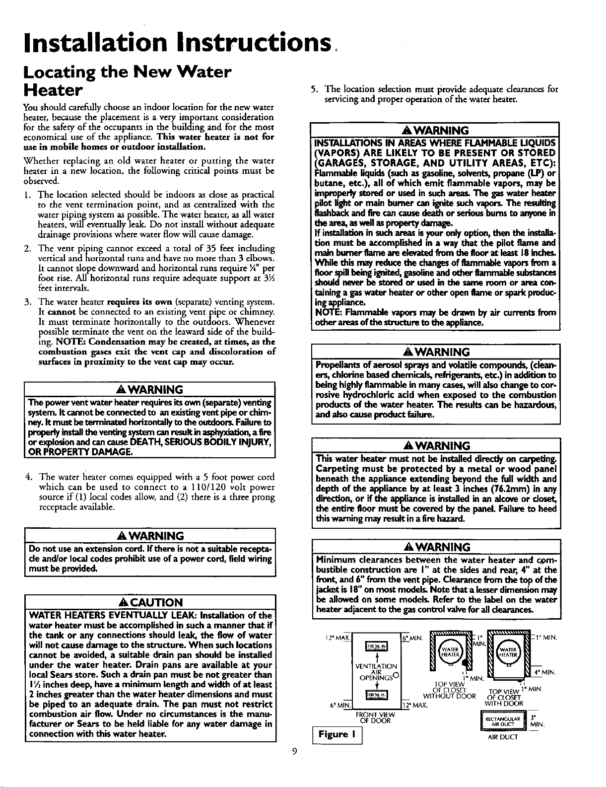
AWARNING
Minimum clearancesbetween the water heater and com-
bustibleconstructionare I" at the sidesandroar, 4" at the
front, and 6" from the vent pipe. Clearance from the top
of the jacket is 18" on most models. Note that a lesser
dimension may be allowed on some models. Refer to the
labelon the water heater adjacent to the gascontrol valve
for all cleerance_
_WARNING I
Do not usethis applianceif any part of it hasbeen under J
Jwater. Immediately call a Sears Service Technician to J
inspectthe applianceandto replace the gascontrol or any
part ofthe burner systemwhich hasbeen under water. J
I AWARNING J
Vent termination must not be within 4 feet of any items J
such as gas meters, gas valves or other gas regulating J
equipment. I
ACAUTION
WATER HEATERS EVENTUALLY LEAK: Installation of
the water heater must be accomplishedin sucha manner
that ifthe tank or any connectionsshould leak,the flow of
water will not causedamageto the structure. When such
locations cannot be avoided a suitable drain pan should
be installed under the water heater. Drain pansare aval-
able at your local Sears store. Such a drain pan must be
not greater than I I/2 inches deep, have a minimum
length and width of at least 2 inches greater than the
water heater dimensionsand must be piped to an ade-
quate drain. The pan must not restrict combustion air
flow. Under no circumstances is the manufacturer or
Sears to be held liable for any water damage in connec-
ionwith this water heater.
_E,WARNING
HYDROGEN GAS: Hydrogengascan be producedin a hot
water systemthat has not been usedfor a long period of
time (generally two weeks or more). Hydrogen gas is
extremely flammable and explosive. To prevent the possi-
bility of injury under these conditions,we recommend the
hot water faucet be opened for several minutes at the
kitchen sink before any electrical appliances which are
connectedto the hot water systemare used(suchasa dis-
hwasber or washingmachine). If hydrogengasis present,
there will probably be an unusual sound similar to air
escaping through the pipe as the hot water faucet is
opened. There must be no smoking or open flame near
the faucetat the time it isopen.
AWARNING
INSULATING JACKETS: When installing an external
water heater insulationjacket ona gaswater heater:
DO NOT cover the temperaturo-prossurerolief valve.
DO NOT put insulation over any part of the top of the
gaswater heater.
DO NOT put insulationoverthe gascontrol valve or gas
control valve/burner cover, or any accessareas to the
burner.
DO NOT let insulationaround the gaswater heater to
get within 8 inches of the floor (air must get to the
burner).
• DO NOT cover or remove operating instructions, and
safety related warninglabelsand materials affixedto the
water heater.
Failureto heed thiswill result in the possibilityof a fire or
explosion.
Table of Contents
Safety Precautions ............. 2-4
Table of Contents ................................................................................................................................................5
Customer
Product
l_esponslt_lllUes.......................................................................................................................6
_pecmcauons ..................................................................................................................................6
Materials and Basic Tools Needed ..........................................................................7
Materials Needed ...................................................................................................................................................................... 7
Basic Tools ................................................................................................................................................................................ 7
Installation Instructions ........................................................................................................................8-20
Removing the Old Water Heater ............................................................................................................................................... 8
Locating the New Water Heater .......................................................................................................................................... 9-10
Combustion Air and Ventilation ............................................................................................................................................. 10
Venting Clearances ............................................................................................................................................................. 10
Combustion Air and Ventilation for Appliances jn Unconfined Spaces ................................................................................... 11
Combustion Air and Ventilation for Appliances in Confined Spaces....................................................................................... 11
Water Piping ........................................................................................................................................................................... 12
Temperature-Pressure Relief Valve........................................................................................................................................... 13
Filling the Water Heater .......................................................................................................................................................... 14
Wiring ............................................................................................................................................................................... 14-15
Venting .............................................................................................................................................................................. 15-18
Gas Piping .............................................................................................................................................................................. 19
Installation Checklist .............................................................................................................................................................. 20
"-""Uperatmg Instructions .........................................................................................................................21-24
Eighting ............................................................................................................................................................................. 22-23
Temperature Remalation...
J 0 '...................................................................................................................................................... 24
Service and Adjustment ......................................................................................................................25-27
Tank (Sedimen0 Cleaning ...................................................................................................................................................... 25
Venting System Inspection ...................................................................................................................................................... 25
Oiling Instructions .................................................................................................................................................................. 25
Burner Inspection ................................................................................................................................................................... 25
Burner Cleaning ..................................................................................................................................................................... 25
L.P. Gas Control Valve & Burner Assembly Replacement Information .................................................................................... 26
Draining ................................................................................................................................................................................. 26
Temperature-Pressure Relief Valve Operation .......................................................................................................................... 26
Drain Valve Washer Replacement .................... 97
Housekeeping ......................................................................................................................................................................... 27
Service .................................................................................................................................................................................... 27
"_ 11 ""lrout)Jestiootmg Guide ........................................................................................................................28-30
Condensation ......................................................................................................................................................................... 28
Smoke/Odor ........................................................................................................................................................................... 28
Thermal Expansion ................................................................................................................................................................. 28
Strange Sounds ....................................................................................................................................................................... 28
Smelly Water ........................................................................................................................................................................... 29
Air in Hot Water Faucets ........................................................................................................................................................ 29
High Temperature Shut OffSystem ........................................................................................................................................ 29
Not Enough Hot Water .......................................................................................................................................................... 29
Water is too Hot ..................................................................................................................................................................... 29
Leakage Checkpoints .............................................................................................................................................................. 30
Parts Order List...............................................................................................................................................32-35
Customer Responsibilities
Thank Youfor purchasing a Searswater heater. Properly
installedand maintained, it should give you years of trouble free ser-
vice. If you should decide that you want the new water heater profes-
sionally installed by Sears call the local Sears Service Center or any
Searsstore. They will arrange for prompt, quality installation by Sears
authorizedcontractors.
Abbreviations Found In This Instruction Manual
A.G.A. - American Gas Association
A.N.S.I. - American National Standards Institute
AWARNING
This gas-fired water heater is design certified by the
American Gas Association Laboratories under American
National Standards for Gas Water Heaters. The installa-
tion must conformwith this manual, Local Codes andwith
the latest edition of the National Fuel Gas Code, ANSI
Z223.1.
This publicationisavailablefrom your focal government or
public library, gas company, or by writing NFPA,
Batterymarch Park,Quincy,MA 02269.
• Read the "Safety Precautions" section, pages 2 and 3 of this
manual first and then the entire manual carefully. If you dont
follow the safety rules, the water heater will not operate prop-
erly. It could cause DEATH, SERIOUS BODILY INJURY
AND/OR PROPERTY DAMAGE.
This manual contains instructions for the installation, op_a-
tion, and maintenance of the gas-fired water heater. It also
contains warnings through out t_e manual that you must read
and be aware of. All warnings and all instructions are essential
to the proper operation of the water heater and your safety.
Since we cannot put everything on the first few pages, READ
THE ENTIRE MANUAL BEFORE ATTEMPTING TO
INSTALL OR OPERATE THE WATER HEATER.
The installation must conform with the instructions in this
manual; gas company rules; and Local Codes, or in the
absence of Local Codes, with the latest edition of the National
Fuel Gas code, ANSI Z223.1, also referred to as NFPA 54.
This publication is available from your local government or
public library or gas company or by writing NFPA,
Batterymarch Park, Quincy, MA 02269.
If afterreading this manualyou have any questions or do not
understand any portion of the instructions, call the Sears
Service Center.
Carefully plan the place where you are going to put the water
heater. Correct combustion, vent action, ana vent pipe instal-
lation are very important in preventing death from possible
carbon monoxide poisoning and fires.
Examine the location to ensure the water heater complies with
the "Locating the New Water Heater" section in this manual.
For California installation this water heater must be braced,
anchored, or strapped to avoid falling or moving during an
earthquake. See instructions for correct installation proce-
dures. Instructions may be obtained from your local dealer,
wholesaler, public utilities or California Office of the State
Architect, 400 P Street, Sacramento, CA 95814.
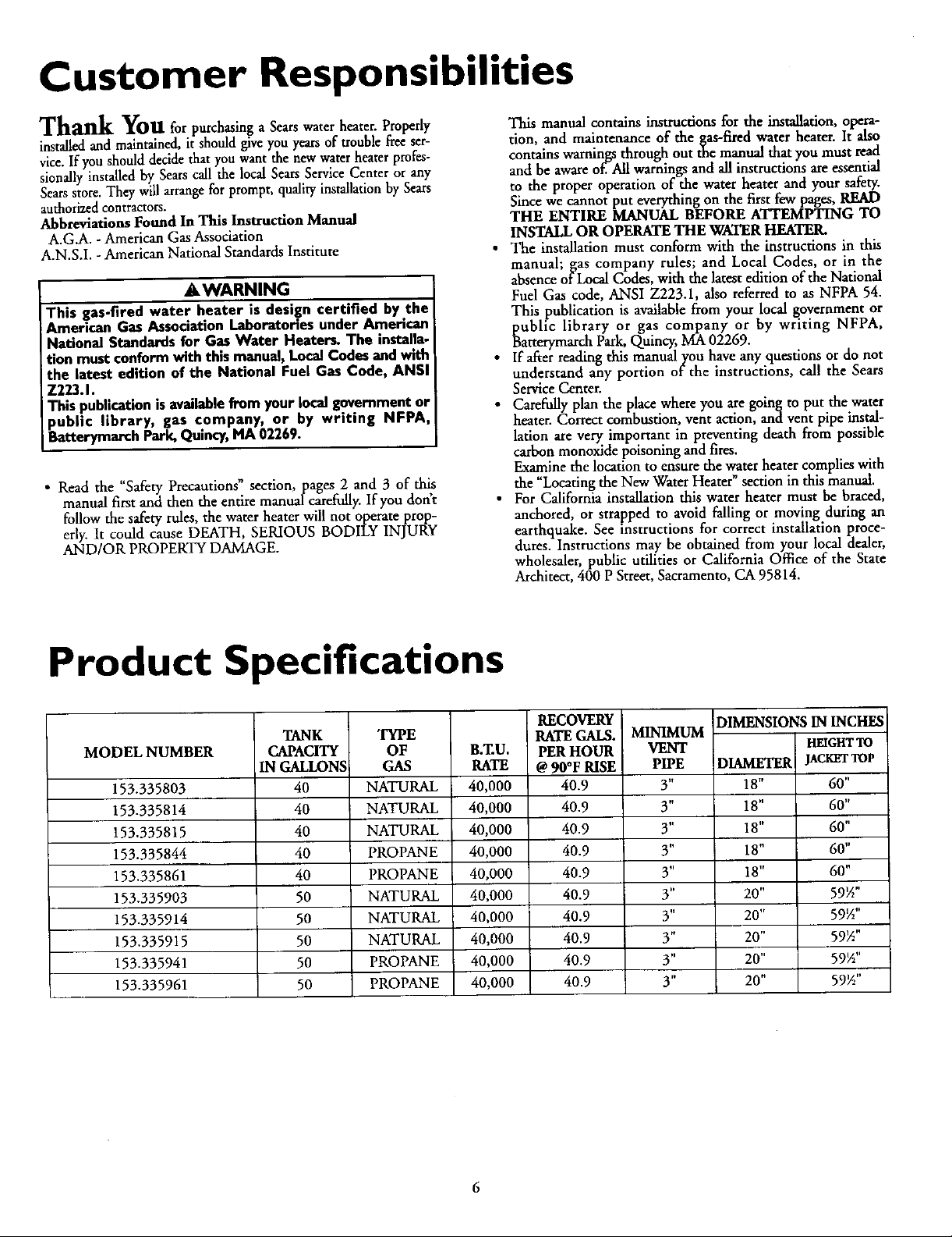
Product Specifications
TYPE
OF
GAS
NATURAL
NATURAL
NATURAL
PROPANE
PROPANE
NATURAL
NATURAL
NATURAL
PROPANE
PROPANE
MODEL NUMBER
153.335803
153.335814
153.335815
153.335844
153.335861
153.335903
153.335914
153.335915
153.335941
153.335961
TANK
CAPACITY
IN GALLONS
40
40
40
40
40
50
50
50
50
50
B.ZU.
RATE
40,000
40,000
40,000
40,000
40,000
40,000
40,000
40,000
40,000
40,000
RECOVERY
RATE GALS.
PER HOUR
@ 90°F RISE
40.9
40.9
40.9
40.9
40.9
40.9
4O.9
40.9
40.9
40.9
MINIMUM
VENT
PIPE
3"
3"
3"
3"
3"
3"
3"
3"
3"
3"
DIMENSIONS IN INCHES
HEIGHT TO
DIAMETER
18"
18"
18"
18"
18"
20"
20"
20"
20"
20"
JACKET TOP
60"
60"
60"
60"
60"
59½"
59½"
59½"
59½"
59½"
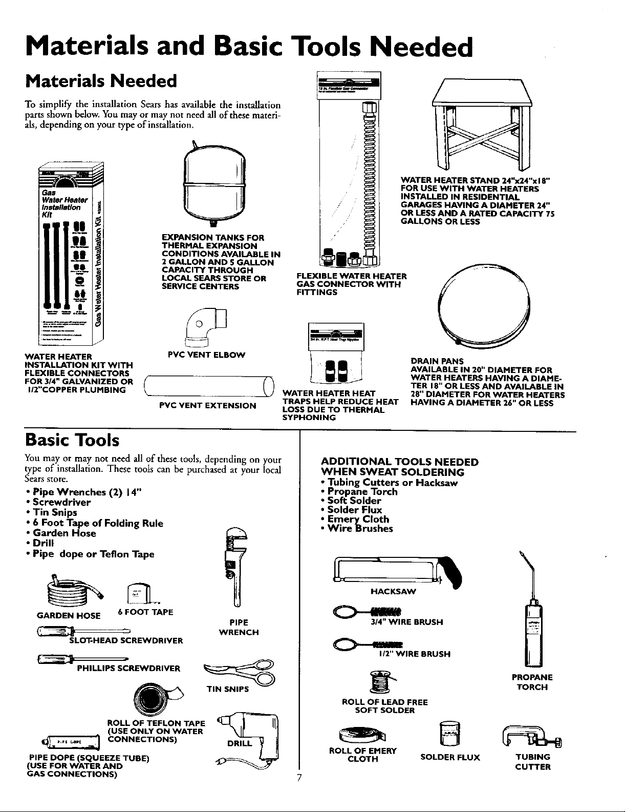
Materials and Basic Tools Needed
Materials Needed
To simplify the installation Sears has available the installation
_larts shown below. You may or may not need all of these materi-
s, depending on your type of installation.
f
WATER HEATER STAND 24"x24"x18"
Gas
Water Heater
Installation
Kit
EXPANSION TANKS FOR
THERMAL EXPANSION
CONDITIONS AVAILABLE IN
2 GALLON AND 5 GALLON
CAPACITY THROUGH
LOCAL SEARS STORE OR
SERVICE CENTERS
/
FLEXIBLE WATER HEATER
GAS CONNECTOR WITH
FITTINGS
FOR USE WITH WATER HEATERS
INSTALLED IN RESIDENTIAL
GARAGES HAVING A DIAMETER 24"
OR LESS AND A RATED CAPACITY 75
GALLONS OR LESS
WATER HEATER
INSTALLATION KIT WITH
FLEXIBLE CONNECTORS
FOR 3/4" GALVANIZED OR
I/2"COPPER PLUMBING
PVC VENT ELBOW
( ()
PVC VENT EXTENSION
Basic Tools
You may or may not need all of these tools, depending on your
type of installation. These tools can be purchased at your local
Sears store.
Pipe Wrenches (2) 14"
Screwdriver
Tin Snips
6 Foot Tape of Folding Rule
Garden Hose
Drill
• Pipe dope or Teflon Tape
GARDEN HOSE 6 FOOT TAPE
SLOT-HEAD SCREWDRIVER
PHILLIPS SCREWDRIVER
ROLL OF TEFLON TAPE
(USE ONLY ON WATER
CONNECTIONS)
PIPE DOPE (SQUEEZE TUBE)
(USE FOR WATER AND
GAS CONNECTIONS)
PIPE
WRENCH
TIN SNIPS
DRILL
WATER HEATER HEAT
TRAPS HELP REDUCE HEAT
LOSS DUE TO THERMAL
SYPHONING
ADDITIONAL TOOLS NEEDED
WHEN SWEAT SOLDERING
Propane Torch
i Tubing Cutters or Hacksaw
Soft Solder
• Solder Flux
_ EmeryCIoth
Wire Brushes
HACKSAW
314" WIRE BRUSH
I/2" WIRE BRUSH
ROLL OF LEAD FREE
SOFT SOLDER
ROLL OF EMERY
CLOTH
7
DRAIN PANS
AVAILABLE IN 20" DIAMETER FOR
WATER HEATERS HAVING A DIAME-
TER 18" OR LESS AND AVAILABLE IN
28" DIAMETER FOR WATER HEATERS
HAVING A DIAMETER 26" OR LESS
PROPANE
TORCH
SOLDER FLUX
TUBING
CUTTER
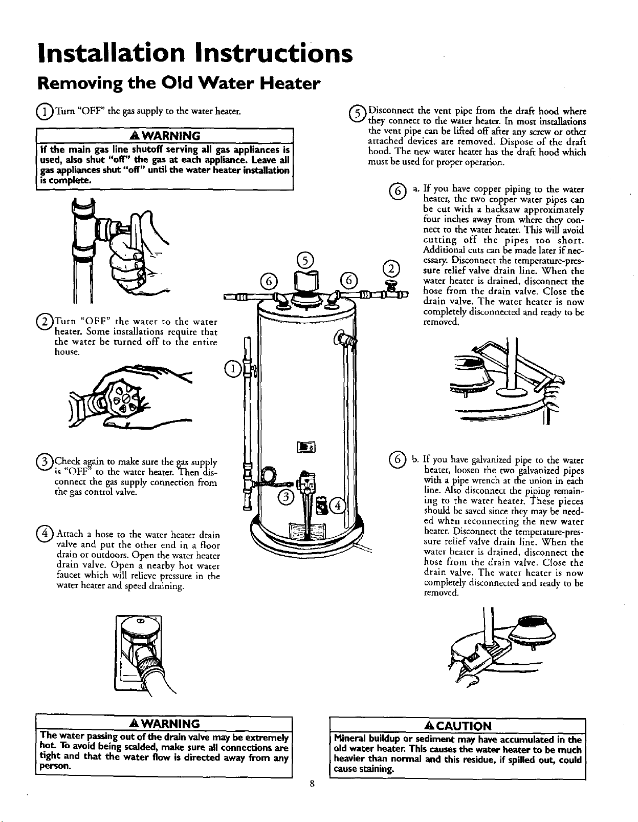
Installation Instructions
Removing the Old Water Heater
Q Turn "OFF" the gas supply to the water heater.
AWARN,. 1
If the main gas line--all gas appliances isl
used, also shut "off" the gas at each appliance. Leave all [
gas appliances shut "off" until the water heater installation I
iscomplete, l
OTurn water to water
_OWP _9 the the
heater. Some installations requite that
the water be turned off to the entire
house,
Q Disconnect the vent pipe from the draft hood where
they connect to the water heater. In most installations
the vent pipe can be lifted off after any screw or other
attached devices are removed. Dispose of the draft
hood. The new water heater has the draft hood which
must be used for proper operation.
G a. If you have copper piping to the water
® ®
heater, the two copper water pipes can
be cut with a hacksaw approximately
four inches away from where they con-
nect to the water heater. This will avoid
cutting off the pipes too short.
Additional cuts can be made later if nec-
essary. Disconnect the temperature-pres-
sure relief valve drain line. When the
water heater is drained, disconnect the
hose from the drain valve. Close the
drain valve. The water heater is now
completely disconnected and ready to be
removed.
QCheck again to make sure the gas supply
is "OFF" to the water heater. Then dis-
connect the gas supply connection from
the gas control valve.
Q Attach a to water heater drain
hose the
valve and put the other end in a floor
drain or outdoors. Open the water heater
drain valve. Open a nearby hot water
faucet which will relieve pressure in the
water heater and speed draining.
...... AWARNING I
The water passingout of the drainvalve may be extremely I
hot. To avoidbeingscalded,make sureall connectionsare [
[ tight and that the water flow is directed away from anyI
I pers°n" I
If you have galvanized pipe to the water
heater, loosen the two galvanized pipes
with a pipe wrench at the union in each
line. Also disconnect the piping remain-
ing to the water heater. These pieces
should be saved since they may be need-
ed when reconnecting the new water
heater. Disconnect the temperature-pres-
sure relief valve drain line. When the
water heater is drained, disconnect the
hose from the drain valve. Close the
drain valve. The water heater is now
completely disconnected and ready to be
removed.
ACAUTION I
Mineral buildupor sedimentmay haveaccumulatedin the }
oldwater heater.Thiscausesthe water heater to be much I
heavier than normal and this residue, if spilledout, could
causestaining.
Installation Instructions
Locating the New Water
Heater
You should carefully choose an indoor location for the new water
heater, because the placement is a very important consideration
for the safety of the occupants in the building and for the most
economical use of the appliance. This water heater is not for
use in mobile homes or outdoor installation.
Whether replacing an old water heater or putting the water
heater in a new location, the following critical points must be
observed.
1. The location selected should be indoors as dose as practical
to the vent termination point, and as centralized with the
water piping system as possible. The water heater, as all water
heaters, will eventually leak. Do not install without adequate
drainage provisions where water flow will cause damage.
2. The vent piping cannot exceed a total of 35 feet including
vertical and horizontal runs and have no more than 3 elbows.
It cannot slope downward and horizontal runs require ¼" per
foot rise. All horizontal runs require adequate support at 3½
feet intervals.
3. The water heater requires its own (separate) venting system.
It cannot be connected to an existing ventpipe or chimney.
It must terminate horizontally to the outdoors. Whenever
possible terminate the vent on the leaward side of the build-
ing. NOTE: Condensation may be created, at times, as the
combustion gases exit the vent cap and discoloration of
surfaces in proximity to the vent cap may occur.
AWARNING
Thepowerventwater heaterrequiresitsown(separate)venting
system.It cannotbe connectedto an existingventpipeor chim-
ney.It mustbeterminatedhorizontallyto theoutdoors.Failureto
properlyinstallt_ ventingsystemcanresultinasphyxiation,aEre
orexplosionandcancauseDEATH,SERIOUSBODILYINJURY,
ORPROPERTYDAMAGE.
4. The water laeater comes equipped with a 5 foot power cord
which can be used to connect to a 110/120 volt power
source if (1) local codes allow, and (2) there is a three prong
receptacle available.
5. The location selection must provide adequate clearances for
servicing and proper operation of the water heater.
AWARNING
INSTALLATIONSIN AREASWHERE FLAMMABLELIQUIDS
(VAPORS) ARE LIKELY TO BE PRESENT OR STORED
GARAGES, STORAGE, AND UTILITY AREAS, ETC):
Flammableliquids(suchasgasoline,solvents,propane(LP) or
butane, etc.), all of which emit flammable vapors,may be
improperlystoredor usedin sucharea_The gaswaterheater
)notlightor mainburnercanignitesuchvapor_The resulting
8ashbeckandfirecancausedeathor seriousburnste anyonein
thearea,aswellaspropertydamage.
If installationinsuchareasisyouronlyoption,thenthe instana-
tion must be accomplished in a waythat the pilotflame and
mainburnerflameareelevatedfromtheBoorat least18inches.
While this mayreducethe changesofflammable vaporsfroma
floor spillbeingignited,gasolineandother8ammablesubstances
shouldneverbe storedor usedinthe sameroom or areacon-
taininga gaswater heaterorotheropen8ameor sparkpnxluc-
ingappliance.
NOTE: Flammablevaporsmaybe drawnbyair currentsfrom
otherareasof thestngtoreto the appliance.
AWARNING
Propellantsof aerosol spraysand volatilecompounds,(ci_m-
ers,chlorinebasedchemicals,refrigerants,etc.) in additionto
being highlyflammableinmanycases,will also changeto cor-
rusive hydrochloricacid when exposedto the combustion
productsofthe water heater.The resultscanbe hazardous
and alsocauseproductfailure.
AWARNING
This water heater must not be installeddirectlyon carpeting.
Carpeting must be protected by a metal or wood panel
beneaththe appliance extending beyondthe full width and
depthof the appliance byat least3 inches(76.2mm) in an)
direction,or if the applianceis installedin an alcoveor closet
the entirefloor mustbe coveredbythe panel.Failureto bee<
this warningmayresult inaErehazard.
AWARNING ]
Do not usean extensioncord.Iftbereisnot a suitablerecepta-
cleand/or localcodesprohibituseofa powercord,fieldwiringI
mustbeprovided. I
ACAUTION
WATER HEATERSEVENTUALLY LEAK:Installationof the
water heater must be accomplished in such a manner that if
the tank or any connectionsshouldleak,the flow of water
will not causedamageto thestructure. When suchlocations
cannotbe avoided,a suitabledrain pan should be installed
under the water heater. Drain pans are available at your
localSearsstore.Sucha drainpan musthe not greater than
1½inchesdeep,havea minimumlengthand widthofat least
2 inchesgreaterthan the water heater dimensionsandmust
be piped to an adequate drain. The pan must not restrict
combustionair flow.Under no circumstancesisthe manu-
facturer or Searsto be held liablefor any water damage in
connectionwith thiswater heater.
AWARNING
Minimum clearancesbetween the water heater and c_m-
bustibleconstructionare I" at the sidesand rear,4" at the
front,and6" fromthe ventpipe.Clearancefromthe topof the
jacketis18"on mostmodelgNote that alesserdimensionmay
be allowedon some models Referto the labelon the water
heateradjacentto the gascontrolvalveforall clearance_
VENTILATION
AIR O
OPENINGS
[# MIN.
FRONT VIEW
OF DOOR
[F,g°.I]
6" MIN. _l}t IjIN" 1" MIN
TOP VIEW ,
OF CLOSET TOP VIE_CV1" MIN.
WITHOUT DOOR OF CLOSET
i_" MAX. WITH DOOR
_l 41"MIN.
AIR DuCT
Installation Instructions (cont'd)
_,WARNING
A gaswnt_ heater cannotoperateproperlywithoutthe cor-
rectamountof air for combustion.Do not im_dl in a confined
area sucha closet, unlessyou provide air as shown in the
"Locating The New Water Heater" section.Never obstruct
theflowofventgationair.Ifyouhaveanydoubtsor questionsat
all, call your gascompany. Failure to provide the proper
amountof combustionair can resultin a fire or explosionand
cancausedeath,seriousbodilyinjury,or propertydamage.
AWARNING
If this water heater will be used in beauty shops,barber shops,
cleaning establishments, or self-service laundries with dry
deaning equipment, it is imperative that the water heater or
water heaters be installed so that combustion and vent_latlou
air be taken from outside these area_ Refer to the "Locating
The New Water Heater" section of this manual and also the
latest edition ofthe National Fuel Gas Code, ANSI Z223.1, also
referred to as NFPA 54 for specifics provided €oncerning air
required,
Combustion Air and Ventilation
Figure 2 I
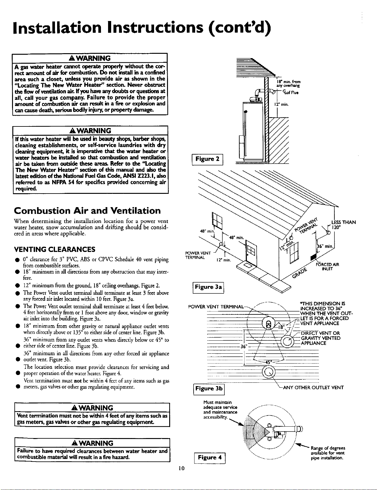
When determining the installation location for apower vent
water heater, snow accumulation and drifting shouldbe consid-
ered in areas where applicable.
VENTING CLEARANCES
• O" clearance for 3" PVC, ABS or CPVC Schedule 40 vent piping
from combustible surfaces.
• 18" minimumin alldirections from any obstruction that mayinter-
fere.
• 12" minimum from the ground, 18" ceiling overhangs.Figure 2.
• The Power Vent oudet terminal shall terminate at least 3 feet above
any forced airinlet located within 10 feet. Figure 3a.
• The Power Vent outlet terminal shall terminate at least 4 feet below,
4 feet hofizontaUy from or I foot above any door, window or gravity
air inlet into the building. Figure 3a.
• 18" minimum from other gravity or natural appliance oudet vents
• either side of center line. Figure 3b.
• outlet vent. Figure 3b.
• proper operationofthewaterheater. Figure4.
• meters, gasvalves or other gas regulating equipment•
Vent termination must not be within 4feet of any items such as
gasmeters, gasvalves or other gasregulating equipment.
• o. , , , ,
when direcdy above or 135 to either side of center hne. Figure 3b.
36" minimum from any outlet vents when directly below or 45° to
36" minimum in all directions from any other forced air appliance
The location selection must provide clearances for servicing and
Vent termination must not be within 4 feet of any items such as gas
a_ WARNING
LESSTHAN
• 120"
POWER VENT
TERMINAL
12" rain.
FORCED AIR
INLET
Figure 3a]
POWERVENTTERMINAL_ _ INCREASEDTO 36"
7_[ \\ / \ _/_VENTOR
f-_ *THISDIMENSIONIS
/ _ _ WHEN THEVENTOUT-
,' [_ LETISFORA FORCED
_/-- VENTAPPLIANCE
GRAVITYVENTED
; i APPL,ANCE
I Figure 3b I
Must main_Jn
adequate service --- ......... ".
arid maiRtenance ///" "',
_-ANY OTHER OUTLET VENT
AWARNING
I Failure to have required clearances between water beater and
Lcombustible material will result in a fire hazard.
// Rangeofdegrees
".. /" availableforvent
[ Figure 4 ] .................. pipeinstallation.
10
Installation Instructions (cont'd)
Combustion Air and Ventilation
for Appliances Located in
Unconfined Spaces
Unconfined Space is a spacewhose volume is not lessthan 50 cubic
feet per 1,000 Btu per hour of the aggregateinput rating of allappli-
ances installed in that space. Rooms communicating directly with the
space in which the appliancesareinstalled, through openingsnot fur-
nishedwith doors, areconsidereda part of the unconfined space.
In unconfined spaces in buildings, infiltration may be adequate to
provide air for combustion, ventilation and dilution of flue gases.
However, in buildings of tight construction (for example, weather
stripping, heavilyinsulated, caulked, vapor barrier, etc.), additionalair
may need to be provided using the methods describedin Combustion
Air and Ventilation for Appliances Locatedin Confined Spaces.
Combustion Air and Ventilation
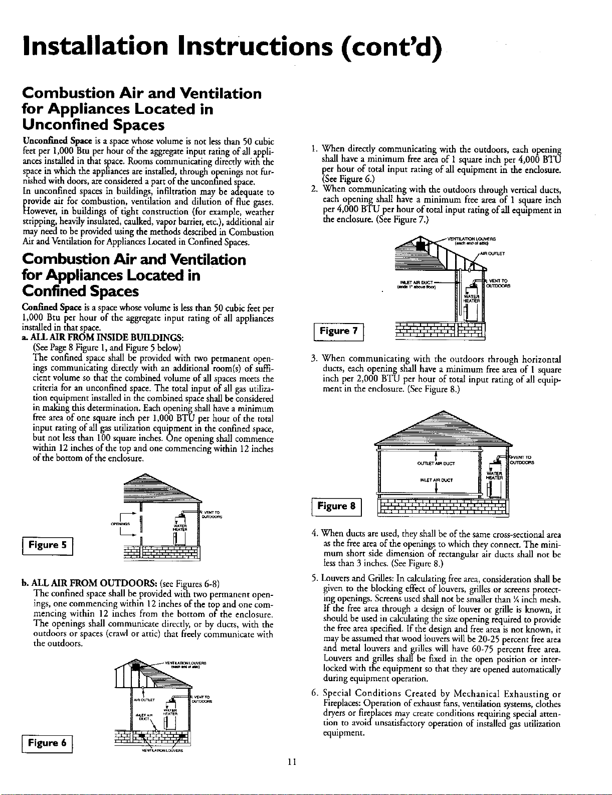
1. When directly communicating with the outdoors, each opening
shall have a minimum free area of 1square inch per 4,000 BTU
per hour of total input rating of all equipment in the enclosure.
(SeeFigure6.)
2. When communicating with the outdoorsthrough vertical ducts,
each opening shall have a minimum free areaof I square inch
per 4,000 BTU per hour of total input rating of allequipment in
the enclosure. (SeeFigure7.)
VENTILAT_ LO_I:_
for Appliances Located in
Confined Spaces
Confined Space is a space whose volume is less than 50 cubic feet per
1,000 Btu per hour of the aggregate input rating of all appliances
installed in that space.
a. ALL AIR FROM INSIDE BUILDINGS:
(See Page 8 Figure 1, and Figure 5 below)
The confined space shall be provided with two permanent open-
ings communicating directly with an additional room(s) of suffi-
cient volume so that the combined volume of all spaces meets the
criteria for an unconfined space. The total input of all gas utiliza-
tion equipment installed in the combined space shall be considered
in making this determination. Each opening shall have a minimum
free area of one square inch per 1,000 BTU per hour of the total
input rating of all gas utilization equipment in the confined space,
but not less than 100 square inches. One opening shall commence
within 12 inches of the top and one commencing within 12 inches
of the bottom of the enclosure.
I Figure 5 [
b. ALL AIR FROM OUTDOORS: (see Figures 6-8)
The confined space shall be provided with two permanent open-
ings, one commencing within 12 inches of the top and one com-
mencing within 12 inches from the bottom orthe enclosure.
The openings shall communicate directly, or by ducts, with the
outdoors or spaces (crawl or attic) that freely communicate with
the outdoors.
Figure 6 1
VENT TO
]O_O0_SIr_=T AIR DOfff
I Figure 7 ]
,,,,,,,,,,,,,,,,A,,,I
3. When communicating with the outdoors through horizontal
ducts, each openingshall have a minimum free area of 1 square
inch per 2,000 BTU per hour of total input rating of all equip-
ment in the enclosure. (SeeFigure8.)
Figure 8 1
4. When ducts are used, they shall be of the same cross-sectional area
as the free area of the openings to which they connect. The mini-
mum short side dimension of rectangular air ducts shall nor be
less than 3 inches. (See Figure 8.)
5. Louvers and Grilles: In calculating free area, consideration shall be
given to the blocking effect of louvers, grilles or screens protect-
ing openings. Screens used shall not be smaller than ¼ inch mesh.
If the free area through a design of louver or grille is known, it
should be used in calculating the size opening required to provide
the free area specified. If the design and free area is not known, it
may be assumed that wood louvers will be 20-25 percent free area
and metal louvers and _rilles will have 60-75 percent free area.
Louvers and .grilles shall be fixed in the open position or inter-
locked with the equipment so that they are opened automatically
during equipment operation.
6. Special Conditions Created b7 Mechanical Exhausting or
Fireplaces: Operation of exhaust fans, ventilation systems, clothes
dryers or firefplaces may create conditions requiring special atten-
tion to avoica unsarisfactory operation of installed gas utilization
eqmpment.
11
CEt4T TO
_LrrlxX;_$

Installation Instructions (cont'd)
Water Piping
AWARNING
HOTTER WATER CAN SCAL_. Water heaters are intended to
produce hot water. Water heated to a temperatu_ which will
satisfyclothes washing, dish washing,and other sanitizing needs
can scaldand pen_anently injure you upon contact, Some peo-
de a_e more like/y to be permanently injured by hot water (_w1n
other_ These indude the elder_, children, the infirm, or physicak
ly/mentally handicapped.If anyone usinghot water in your home
Etsinto one ofthese groupsor if thore isa local code or state law
_ ac_ain _ra_rau_ wat_- at the hot wa_erta_ th_
_u must take spechl preca_on_ In addition to using the
possibletemperatu_ settingthat satisfiesyour hot water needs,
l ameans such asa mixing valve, shouldbe used at the hot water
taps usedby these people or at the water heote_.Mbdng valves
are availableat plumbing supplyor hardware store_ Follow man-
ufacturers instructions for installation of the valves. Before
changing the factory setting on the thermostat, read the
'_remperatore Regulation" sectionin this manual
This water heater shall not be connected to any heating systems
or component(s) used with a non-potable water heating appli-
ance.
If a water heater is installed in a closed water supply system;
such as one having a back-flow preventer, check valve, water
meter with a check valve, etc.., in the cold water supply; means
shall be provided to control thermal expansion. Contact the
local utility or local Sears Service Center on how to control this
situation.
NOTE: To protect against untimely corrosion of hot and
cold water fittings, it is strongly recommended that didec-
tric unions or couplings be installed on this water heater
when connected to copper pope.
2. Look at the top cover of the water heater. The cold water
inlet is markedcold. Put two or three turns of teflon tape
around the threaded end of _e threaded-to-swear coupling
and around both ends of the ¾ threaded nipple. Using flexi-
ble connectors, connect the cold water pipe to the coldwater
inlet of the water heater.
NOTE: This water heater is insulated to minimize heat
loss from the tank. Further reduction in heat loss can be
accomplished by insulating the hot water lines from the
water heater.
INSTALLATION COMPLETED USING
SEARS INSTALLATION KIT
COLD INLET
WATER LINE
3/4"THREADED
NIPPLE
TEMPERATURE-
PRESSURERELIEF
VALVE
THREADED TO
SVVEATCOUPLING
HOT OUTLET
TO HOUSE
NIPPLE
THREADED TO SHUTOFF
SVVEATCOUPUNG VALVE
The illustration shows the attachment of the water piping to the
water heater. The water heater is equipped with 3/4inch water
connections.
NOTE: If using copper tubing, solder tubing to an adapter
before attaching the adapter to the cold water inlet connec-
tion. Do not solder the cold water supply line directly to the
cold water inlet or it will harm the dip tube.
1. Look at the top cover of the water heater. The hot water outlet is
marked hot. Put two or three turns of teflon tape around the
threaded end of the threaded-to-sweat coupling and around both
ends of the ¾" threaded nipple. Using flexible connectors, con-
nect the hot water pipe to the hot water outlet on the water
heater.
DISCHARGE PIPE
(Do not capor plug)
PROVIDE A 6" AIR
GAP BETWEEN THE
END OF THE
DISCHARGE PIPE
AND DRAIN
12

Installation Instructions (cont'd)
Temperature-Pressure Relief Valve
AWARNING
At the time of manufacturethiswater heaterwas provided
witha combinationtemperature-pressuresreliefvalvecertified
bya nationallyrecognized testinglaboratory that maintains
periodicinspec_onof productionof listedequipmentormate-
rials, as meeting the requirements for Relief Valves and
AutomaticGasShutoffDevicesfurHot Water SupplySystems,
and the latesteditionof ANSI Z21.22and the coderequire-
mentsofASME.If replaced,the valvemust meet the _luire-
mentsoflocalcedes,butnotlessthan acombinationtempera-
ture and pressurerelief valvecertifiedasmeetingthe require-
meritsfur ReliefValvesandAutomaticGasShutoffDevicesfor
Hot Water SupplySystems,ANSI 7.21.22bya nationallyrecog-
nizedtestinglaboratorythat maintainsperiodicinspectionof
productionoflistedequipment or materials
The valvemustbe markedwith a maximumsetpressurenot
to exceedthe marked hydrostaticworking pressureof the
water heater(150IbsJsq.in.) anda dischargecapacitynot less
than the water heaterinputrate asshownonthe modelrating
plate.(Electricheaters- watts dividedby 1000x 3415 equal
BTU/Hr.rate.)
Yourlocaljurisdictionalauthority,whilemandatingthe useofa
temperature-pressurereliefvaivecomplyingwithANSI Z21.22
andASME,may require a valvemodel differentfromthe one
furnishedwiththe water heater.
Compliancewith suchlocalrequirementsmustbe satisfiedby
the installeror end userofthe waterheaterwith a locallypre-
scribedtemperature-pressurerelief valveinstalledin the desig-
nated openinginthe water heater in placeofthe factory fur-
nishedvalve.
Forsafeoperationofthe water heater,the reliefvalvemustnot
beremovedfromit'sdesignatedopeningor plugged.
Thetemperature-pressurerelief valvemustbe installeddirectly
intothe fittingofthewaterheaterdesignatedforthe reliefvalve.
Positionthe valvedownwardandprovidetubingsothat anydis-
chargewill exit onlywithin6 inchesabove,or at any distance
belowthe structuralfloor.Be certainthat no contactismade
withanyliveelectricalpart.The dischargeopeningmustnotbe
blockedor reduced in sizeunderany circumstancesExcessive
length,over30feet,or useofmorethan fourelbowscancause
restrictionandreducethedischargecapacityofthevalve.
No valveor otherobstructionisto be placedbetweenthe relief
valveandthe tank.Do not connecttubing directlyto discharge
drainunlessa 6"air gapisprovided.Topreventbodilyinjury,haz-
ardto life,or propertydamage,the relief valvemustbeallowed
todischargewaterinquantitiesshouldcircumstancesdemand.If
the dischargepipeisnot connectedto a drainor othersuitable
means,thewaterflowmaycausepropertydamage.
The DischargePipe:
• Mustnot be smaiierin sizethan the outletpipesizeof the
valve,or haveanyreducingcouplingsor otherrestrictions.
• Mustnot bepluggedor blocked.
• Mustbeof materiallistedforhotwaterdistribution.
• Mustbe installedsoas to allowcompletedrainageof both
the temperature-pressurerelief valve, andthe discharge
pipe.
• Mustterminateat anadequatedrain.
• Mustnothaveanyvalvebetweenthe relief valveandtank.
AWARNING
The temperature-pressure relief valve must be manually
operated at least once a _ Cautionshouldbe taken to
ensurethat (I) no one isin frontof or aroundthe outiot of
the temperature-pressure relief valvedischargeI'me,and (2)
the water manually dischargedwill not causeany bodily
mjury or property damage because the water may be
ex_mely hot.
If after manuallyoper_Jng the valve, it fails to completely
resetand continuesto releasewater,immediatelyclosethe
cold water inlet to the water heater, follow the draining
instructions,and replace the temperatore-preasure relief
valvewitha new one.
TEMPERATURE-PRESSURE
RFJJEF VALVE
HOT
(Do not cap or plug)
PROVIDE A 6" AIR
GAP BETWEEN
THE END OF THE
DISCHARGE PIPE
AND DRAIN
RELIEFVALVEOPENING
At the time of manufacture, this water heater wasprovided with a cornbinadontern-
perature-pressurerelief valve listedas complyingwith the standardfor relief valvesand
automatic gas shut-off devices for hot water supplysystems, ANSI Z21.22. For safe
operation of the water heater,the relief valvemust not be removed from its designated
point of installationor plugged.
Your local jurisdictional authority,while mandating the use of a temperature-pressure
relief valve complyingwith ANSI Z21.22 and ASME, mayrequire a valvemodel different
from the one furnishedwith the water heart.
Compliancewith such local requirementsmust be satisfied by the installeror end user
of the water heater with a locally prescribedtemperature-pressure relief valveinstalled
inthe designated openingin the water heater.
See manual heading-"Temperature-Pressure Relief Vahres"for installationand mainte-
nanceof relief valve, dischargeline,and other safetyprecautions.
13

Installation Instructions (cont'd)
Filling the Water Heater
You must provide all wiring of the proper size outside of the
ACAUTION
Never usethiswater heater unlessit iscompletelyElledwith
water,To preventdamageto the tank, thetankmustbeElled
with water. Water must flow from the hot water faucet
beforeturning"ON" gasto the water heater,
water heater. You must obey local codes and electric company
requirements when you install this wiring.
Ifyou are not familiar with electric codes and practices, or ifyou
have any doubt, even the slightest doubt, in your ability to con-
nect the wiring to this water heater, obtain the service of a com-
petent electrician or contact your local electric utility.
To fill the water heater with water:
Close the water heater drain valve by turning the handle to
the right (clockwise). The drain valve is on the lower front of
the water heater.
• Open the cold water supply valve to the water heater.
NOTE: The cold water supply valve must be left open
when the water heater is in use.
• To insure complete filling of the tank, allow air to exit by
opening the nearest hot water faucet. Allow water to run
until a constant flow is obtained. This will let air out of the
water heater and the piping.
• Check allnew water piping for leaks. Repair as needed.
Wiring
USE WITH POWER CORD
The water heater comes equipped with a 5 foot power cord
which can be used to connect to a 110/120 volt power source if,
(1) local codes allow, and (2) there is a three prong receptacle
available.
\
\
\
\
\
\
\
\
\
\
\
5' MAXIMUM
CORD LENGTH
(Factorysupplied)
AWARNING
WATER HEATERSEQUIPPED FOR ONE TYPE VOLTAGE
ONLY:Thiswaterheaterisequippedfor 1101120voltsonly.DO
NOT USE THIS WATER HEATERWITH ANY VOLTAGE
OTHERTHAN THE ONE SHOWN ABOVE.Failuretousethe
correctvoltagecancauseproblemswhichcanresultinDEATH,
SERIOUSBODILY INJURYOR PROPERTYDAMAGE.If you
havenayquestionsor doubtsconsultyour electriccompany.
A CAUTION
If wiring from the fusebox or circuitbreaker box was alu-
minumfor the oldwater heater,replace it with copperwire.
If you wishto reuse the existing aluminum wire, havethe
connectionat the water heater made by a competent elec-
trician.Contacta localelectrical contractorand/orthe local
electricutility.
USE WITHOUT POWER CORD
If power cord cannot be used, then follow these wiring instruc-
tions.
1. Provide a way to easily shut off the electric power when work-
ing on the water heater. This could be with a circuit breaker
or fuse block in the entrance box or a separate disconnect
switch.
2. Install and connect a circuit directly from the main fuse or
circuit breaker box. This circuit must be the right size and
have its own fuse or circuit breaker.
\
\
\
You must provide all wiring, (1) to a receptacle or, (2) between
the water heater and junction box when the power cord is nor
used.
_,WARNING ]
Do notuseanextensioncord.Ifthereisnota suitablerecepta-J
tie and/or localcodesprohibituseofa powercord,fieldwiringI
must beprovided, J
14
GREEN
GROUND SCREW

Installation Instructions (cont'd)
USE WITHOUT POWER CORD (cont'd)
3. A standard ½" conduit opening has been made in the water
heater junction box for the conduit connection.
4. Use wire nuts and connect the power supply wiring to the
wires "ns'de the water heaters junction box.
5. The water heater must be electrically _grounded" by the
installer. A green ground screw has been provided on the
WIRING DIAGRAM
SgflT_4
S_T_H
water heater's junction box. Connect ground wire to this
location. For complete grounding details and all allowable
exceptions, refer to the latest edition of the National
Electrical Code.
6. Replace the wiring junction cover using the screw
provided.
Venting
_WARNING I
Toinsureproperventingofthisgas-Eredwater heater,the cot- I
rect vent pipe diameter must be utilized.Any additionsof I
other gas applianceson vent with this water heater will
adverselyaffectthe operationofthe water heater.
The combustion and ventilation air flow must not be obstructed.
a_WARNING I
The water heater with draft hood installed must be properly I
vented to a chimney which terminates outdoors. Never oper-
_e the water heater unlessit isvented to the outdoors and has
adequate air supply to avoid risksof improper operation explo-
sion or asphyxiation.
&WARNING I
Obstructed or deteriorated vent systems may present a serious
health risk or asphyxiation.
The vent pipe from the water heater must be 3 diameter I
•,WARNING ,, I
PVC schedule 40 pipe and must slope upward I/4 inch per
near foot.
All vent gases must be completely vented to the outdoors of the
structure (dwelling).
Min. rise I/4"
perfoot
A,WARNING
Failureto haverequiredclearancesbetweenwater heaterand
combustiblematerialwillresultinafire hazard.
15

Installation Instructions (cont'd)
Venting (cont'd)
AWARNING
Be sure vent pipe is p,_porly connected to prevent escape of
dangerousflue gaseswhich couldcausedeadly asphyxiation,
AWARNING
Chemical vapor corrosion of the Rue and vent system may
occur if air for combustion contains certain chemical vapors,
Spray can propellants, cleaning solvents, refrigerator and air
conditioner refrigerants, swimming pool chemicals, calcium
and sodium chloride, waxes, bleach, and processchemicals are
typical compoundswhich are potentially corrosive.
3" PVC SCHEDULE 40 VENT PIPING
Supplied in the carton with the water heater are:
1. A 3" PVC Schedule 40-45 ° vent cap with wire screen.
2. A 3" PVC Schedule 40-90 ° street ell; used to connect the
vent pipe to the water heater when the vent pipe is to be
turned horizontally directly off the blower.
3. A 5' section of 3" PVC Schedule 40 pipe (more may be
required and must be supplied locally).
3"opvcSchedule40
90 Elbow
VENTING SYSTEM EXAMPLE INSTALLATIONS
FOR ALL MODELS
The vent piping cannot under any circumstances be run down-
hill.
The vent piping can be installed as follows:
1.No more than 3 elbows can be used.
Max. 3
MIN. RISE ¼"
PER FOOT
Vent Cap with
Screen
1
1. The water heater requires its own (separate) venting
system.
2. 3" PVC, ABS or CPVC Schedule 40 piping and fittings are
acceptable materials for the vent system on all 40 gallon
models and 50 gallon 40,000 BTU/HR models.
3. It cannot be connected to existing vent piping or
chimney.
4. It must terminate horizontally to the outdoors.
MAX. 20'
MAX_3
MIN. RISE ¼"
PER FOOT
TOTAL VERTICAL AND
HORIZONTAL RUNS
CANNOT EXCEED 35'
MIN. RISE ¼"
PER FOOT
TOTAL VERTICAL AND
HORIZONTAL RUNS
CANNOT EXCEED 35'
16

Installation Instructions (cont'd)
VENTING SYSTEM EXAMPLE INSTALLATIONS
FOR ALL MODELS (cont'd)
2. Horizontal runs require a minimum ¼" rise per foot.
35' Max.
16"MIN.
13" MIN. Min. rise ¼"
I1" MIN. per foot
3. A vertical run can be no more than 20'.
4. The total vertical and horizontal run cannot exceed 35'.
Min. rise ¼"
OneElbow perfoot
Ma_ 20'
CEMENTING PVC, ABS OR CPVC PIPE AND FITHNGS
Read and observe all safety information printed on primer,
cleaner, and cement containers.
DANGER
Primer, cleaner, and cements are extremely flammable.
They are harmful or fatal if swallowed. The vapors are
harmful. They may irritate eyes and skin and can be
absorbed through the skin.
PRECAUTIONS
Always store primers, cleaner, and cements in cool, dry,
well ventilated places. Do not store them near heat,
sparks, or flames. Keep containers closed. Use them in
well ventilated areas. Wear impervious clothing while
handling. Do not smoke, eat, or drink while handling.
Wash thoroughly after handling and before eating. Wear
eye protection when handling. If swallowed, drink water,
do not induce vomiting, and call a physician or poison
control center immediately. If inhaled, get fresh air and
seek medical attention if ill feelings persist. In case of
eye and skin contact, immediately flush with plenty of
water for 15 minutes and seek medical attention if irri-
tation persists. KEEP OUT OR REACH OF CHILDREN.
All primers, cleaners, and cements must meet all local codes and
applicable standards of the American Society For Testing
Materials Standards.
Before using primers, cleaners, and cements, stir or shake, mak-
in sure contents are liquid. Do not use if found to be lumpy or
jei_;-like.
I I
T
Max.20'
I
Min. rise ¼"
per foot
TOTAL VERTICAL AND
HORIZONTAL RUNS
CANNOT EXCEED 35'
Min. rise ¼"
per foot
TOTAL VERTICAL AND
HORIZONTAL RUNS
CANNOT EXCEED 35'
1. Cut pipe ends squarely removing all burrs and dirt.
2. Dry fit pipe and fittings to be connected for proper fit.
3. Clean pipe and fitting with a primer/cleaner.
4. Apply a thin coat of cement to fitting, avoiding puddling
inside.
5. Apply a liberal coat of cement to pipe leaving no voids.
6. QUICKLY assemble parts while cement is fluid! If you wait
too long, re-coar pipes.
7. Push pipe completely into socket of fitting, turning as it goes
until it bottoms.
8. Hold pipe and fitting together for 30 seconds. Then carefully
clean off excess with a cloth. Allow connections a sufficient
time to cure before disturbing.
9. Remember that vent pipes must be adequately and securely
supported.
APPROXIMATE SETTING TIME FOR 2½" TO 4" PIPE
OINTS
MOVEMENT COMPLETE
OF JOINT SET
90°F to 150°F 3Ahr. 8 hrs.
50°F to 90°F 1 hr. 15 hrs.
0°F to 50°F 1_ hr. 18 hrs.
17

Installation Instructions (cont'd)
Venting (cont'd)
CUTTING OPENING THROUGH AN OUTSIDE
WALL AND COLLAR INSTALLATION
After readingthe manual and you have determined the location
of the opening in the wall, (using the drawing below), cut a 3½"
hole through an exterior wall.
NOTE: When determining location of the opening in the
outside wall allow for the ¼" rise per foot that has taken
place in the horizontal run.
CL of Flue--_....... _ "_[_t
?-
40 gal.-60"
50Gal.-59½"
CONNECTING PVC, ABS OR CPVC PIPE VENT TO
BLOWER
1. The manufacturer has supphed a 3 PVC or ABS Schedule
street elbow for connection to the water heater when turning
immediately horizontally off the blower• Place the elbow in
the required direction on the blower and usinl_ 3 sheet metal
screws, attach the elbow. If using a galvanized elbow attach-
ment is the same.
• " 40
I I
2. If there is to be a vertical run of vent from the blower, the 3"
PVC, ABS or galvanized pipe must be attached to the blower
using 3 sheet metal screws. If using galvanized piping attach-
ment is the same. Additionally, you must seal all joints using a
suitable silicone sealer such as GE RTV-103 or equivalent.
_r
The Y' PVC Schedule 40 vent pipe can be run from the water
heater through the wall or from the wall to the water heater,
whichever is most convenient. The vent pipe must extend a
minimum of 1½" through the exterior wall. Extending the vent
cap as far as possible from the surface of the exterior wall will
help minimize discoloration of the wall in this area which may
be caused by the flue gases. Note that the inside collar must be
slipped over the vent piping before locating the pipe through the
wall. Before securin_ the inside and outside collars to the wall,
use a silicone sealer between pipe and opening to insure a water
and air tight seal.
INSTALLATION SHOWING USE OF PVC, ABS OR
CPVC PIPE
SEALER
SILICONE_
__ 1 +h" MIN.EXTENSION
THROUGH
EXTERIOR WALL
SCREW
SEALER
VENT CAP MUST BE
_ POSITIONED
DOWNWARD
SCREEN
18

Installation Instructions (cont'd)
Gas Piping
I AWARNING ]
Make sure the gassure type listed on the I
modelrating plate. The inlet gaspressuremust not exceed
14incheswater column 'Apoundper squareinch(3.5kPa)].I
The minimum inlet gaspressurelistedon the model rating I
plateisforthe purposeof inputadjustment.
AWARNING , J
Ifthe gascontrolvalveissubjectedto pressuresexceeding'A
poundper square inch(3.5kPa),the damageto the gascon-
trolvalvecouldresult ina fireor expiosionfrom leakingga_ J
AWARNING
If the main gasline shutoffservingall gasappliancesisused,
alsotorn "off" the gasat eachappliance.Leaveall gasappli-
ancesshutoff untildm water heaterinstallationiscomplete.
A gas line of sufficient size must be run to the water heater.
Consult the latest edition of National Fuel Gas Code ANSI
Z223.1, also referred to as NFPA54 and the gas company con-
cerning pipe size.
There must be:
•A readily accessible manual shut off valve in the gas supply line
serving the water heater, and
•A drip leg (sediment trap) aheadof the gas control valve to help
prevent dirt and foreign materials from entering the gas control
ValVe.
•A flexible gas connector or a ground joint union between the
shutoffvalve and control valve to permit servicing of the unit.
f AWARNING J
Use pipe joint €omp_tape marked as beingI
resistantto the actionofpetroleum [Propane(LR)] gese_ 1
SEDIMENT TRAP
A sediment trap shall be installed as close to the inlet of the
water heater as practical at the time of water heater installation.
The sediment trap shall be either a tee fitting with a capped nip-
ple in the bottom outlet or other device recognized as an effec-
tive sediment trap. If a tee fitting is used, it shall be installed in
conformance with one of the methods of installation shown
below.
Connecting the gas piping to the gas control valve of the water
heater can be accomplished by either of the two methods shown.
GAS PIPING WITH
FLEXIBLE CONNECTOR
MANUAL _('AS SUPPLY PIPING
SHUTOFF
VALVE
FLEXIBLE G_S CONNECTOR
LABELED AS COMPLYING
WITH ANSI STANDARDS
GROUND
UNION (Optional)
DRIP LEG
(Sediment trap)
CAP
GAS
CONTROL
VALVE
Be sure to check all the gas piping for leaks before li_hting the
water heater. Use a soapy water solution, not a match or open
flame. Rinse offsoapy solution and wipe dry.
Standard Models are for installation up to 3,300 feet above sea
level.
High Altitude Models are for installation from 3,300 to 5,500
feet above sea level.
Ifa standard model is installed above 3,300 feet or a high altitude
model is installed above 5,500 feet, the input rating must be
reduced at the rate of 4 percent for each 1,000 feet above sea level.
Contact your local Sears Service Center or gas utility for further
information.
The appliance and its gas connectionmust
beforeplacingthe appliancein operation.
AWARNING be leak tested
AWARNING
•The applianceand its individualshutoffvalvemust be discon-
nectedfromthe gassupplypipingsystemduringanypressure
testingofthe gassystemat test pressuresin excessof I/2
poundpersquareinch(3.5kPa).
•The appliancemust beisolatedfromthe gassupplypipingsys-
tem byclosingits individualmanualshutoffvalveduringany
pressuretestingof the gassupplypipingsystemat test pres-
suresequalorlessthan I/2 poundper squareinch(3.5kPa).
GAS PIPING WITH ALL BLACK IRON
PIPE TO GAS CONTROL
SHUTOFF
VALVE
MANUAL_;ASSUPPLY PIING
GROUND lOIN1
UNION
T
6"
BLACK PIPE
DRIP LEG
(Sediment t_ap)
CAP
GAS
CONTROL
VALVE
&WARNING
Contaminants in thegaslinesmaycauseimproperoperation
of the gascontrolvalvethat may resultin fire or explosion.
Beforeattachingthe gasline be surethat all gaspipeisclean
on the inside.Totrap any dirt or foreign material in the gas
supplyline, a drip leg (sometimes calleda sediment trap)
must be incorporated in the piping.The drip leg must be
readily accessible.Installinaccordancewiththe "Gas Piping"
section.Referto the latestedition of the National Fuel Gas
Code,ANSI Z223.1,alsoreferred to as NFPA 54.
19

Installation Instructions (cont'd)
Installation Checklist
BEFORE LIGHTING THE PILOT:
• Check the gas lines for leaks.
a. Use a soapy water solution. DO NOT test for gas leaks
usinga match or open flame.
b. Brush the soapy water solution on all gas pipes, joints and
fittings.
c. Check for bubbling soap. This means you have a leak.
Turn OFF gas andmake the necessary repairs.
d. Recheck for leaks.
e. Rinse off soapy solution and wipe dry.
Is the new temperature-pressure relief valve properly installed
and piped to an adequate drain? See "Temperature-Pressure
Relief Valve" section.
Are the cold and hot water lines connected to the water
heater correctly? See "Water Piping" instructions in the
"Installing the New Water Heater" section.
• Is the water heater completely filled with water? See "Filling"
instructions in the "Installing the New Water Heater" sec-
tion.
• Will a water leak damage anything? See the "Locating the
New Water Heater sectmn.
VENT PIPETO
OUTDOORS
COLD
SHUTOFF
VALVE
TEt4PERATURE-
PRESSURERELIEF
VALVE
DISCHARGE PIPE
Is there proper clearance between the water heater and any-
thing that might catch fire? See the "Locating the New water
Heater section.
Do you have adequate ventilation so that the water heater
will operate properly? See ' Combust'on A'r and Vent'lation"
in the 'Locating the New Water Heater" sect'on.
Is the draft hood vent piping properly secured? See "Venting"
instructions in the "Installing the New Water Heater" sec-
tion.
Is there proper clearance between the vent pipe and anything
that might catch on fire? See 'Venting instructions in the
"Installing the New Water Heater" section.
Is the vent pipe properly sloped and does the vent terminate
outdoors? See "Venting" instructions in the "Installing the
New Water Heater" section.
(Sediment trap)
PIPECAP
Do you need to call your gas company to check the gas pipe
and its hookup?
CHECK FOR LEAKS
Be sure to check all your gas pipes for leaks before lighting your
water heater. Use a soapy water solution, not a match or open
flame. Check the factory gas,,fittings after pilot is lit and gas con-
trol knob is still in PILOT position. Then, check the fittings
when the main burner is turned "ON". Use a soapy water solu-
tion for this, too. MODEL RATING PLATE
20

Operating Instructions -
This water heater is equipped with an electrically operated vent-
ing system and a standing pilot. For the burner to come on, the
water heater thermostat must call for heat. Then the system will
begin sequencing, each section proving itself before gas is
allowed to flow to the burner.
BEFORE THE WATER HEATER WILL OPERATE:
BLOWER MOTOR
1. The control system must be connected to a 110/120 volt
power supply. The control system has an overall rating of 2
amps. The water heater must be securely and adequately
grounded in accordance with local codes and with the latest
edition of the Nationa! Electrical Code ANSI/NFPA 70.
2. The ON/OFF toggle switch, located on the control box
above the thermostat must be in the "ON" position for the
electrical control system to operate allowing the gas portion
to operate (ignite burner).
3. The pilot must be lit. See Lighting instructions on page 22
of this manual or located adjacent to the thermostat on the
water heater.
4. The gas control knob located on the thermostat must be
turned to the "ON" position for the gas to be able to flow.
5. The venting manual reset switch must be in the dosed posi-
tion. See Venting Manual Reset Switch in the For Your
Information Section".
6. There is a non-resettable hi-limit switch in the thermostat,
which must be good (dosed) for the thermostat to be o_er-
ated. See 'High Temperature Shut Off System in the For
Your Information Section".
OPERATION
VENTING
RESET SVVITCH
DRAFT HOOD
ON/OFF SWITCH ,SWITCH
24V/120V
TRANSF_
GAS CONTROL
KNOB,
AIR PRESSURE
GAS PRESSURE
SWITCH
When the thermostat calls for heat, gas in allowed to flow to a
(Normally open) pressure switch closing it. An electrical circuit
is then made to the blower, turning it on. The indicator light
located on the control box will come on. When the blower has
achieved sufficient venting, the airpressure switch will dose and
the indicator light will go off. A 24volt circuit will be complet-
ed through the venting manual reset switch and on to the 24
volt gas valve located just below the thermostat. The 24 volt gas
valve will open allowing gas to flow to the burner. The standing
pilot will establish a main burner flame.
BURNER
GAS THERMOSTAT
THERMOCOUPLE
21

Operating Instructions
Lighting
A,WARNING
BEFORE LIGHTING [PROPANE (L.R) GAS WATER
HEATERS]: Propane (I.R) gas is heavier than air. Should there
be a leak in the system, the gas will settle near the ground.
Basements, crawl spaces, skirted areas under mobile homes
(evenwhen ventilated), closetsand areas below ground leve_will
serve as pockets for the accumulation of this gas. Before
attemp_ng to light or relight the wZer heater's pilot or turning
on a nearby electrical lightswitch, be absolutely surethem isno
accumulated gas inthe area. Search for odor of gasby miffingat
ground level in the vicinity of the appliance. If odor isdetected,
follow stepsindicated at "For Your Safety" on the cover page of
this manual then leavethe premises.
Lighting and operating instructions are located on front of the
water heater, above or to one side of the gas control valve.
Figure 9 ]
AWARNING
AN ODORANT IS ADDED TO THE GAS USED
BY THIS WATER HEATER.
FOR YOUR SAFETY
IF YOU SMELL GAS:
Do not try to light any appliance.
Do not touch any electrical switch; do not use any phone in
your building.
Immediately caJlyour gas supplier from a neighbor's phone.
Follow the gassupplier_sinstructions.
If you cannot reach your gas supplier, call the fire depart-
ment.
_,WARNING
DO NOT forcethe gascontrolknob.Use only your handto
pushit downto lightthe pilot,or to tom it to "ON", "OFF"
or "PILOT". Never usea tool suchas a lever,wrenchor pli-
ers. Do not hit or damagethe knob. A damagedknob may
resultin an explosionandseriousinjury.If youhaveproblem
turningthe knob, callthe gassupplier immediately.
CHECK FOR LEAKS
Be sure to check all your gas pipes for leaks before lighting your
water heater. Use a soapy water solution, not a match or open
flame. Check the factory gas ,fittings after pilot is lit and gas con-
trol knob is still in PILOT pos!tion,, Then, check the fittings
when the main burner is turned ON . Use a soapy water solu-
tion for this, too.
Figure 10]
Figure I I]
INNER DOOR
OUTER DOOR
22
Figure 12]

Operating Instructions (cont'd)
Lighting label on the water heater as it appears above the thermostat
FOR YOUR SAFETY READ BEFORE LIGHTING
If you do not follow these instructions exactly, a fire or explosion
may result causing property damage, personal injury or loss of life.
A. Thisappfiancehas a pilot whichmustbe lightedby
hand.Whenlightingthe pilot,followtheseinstructions
exactly.
B. BEFORELIGHTINGsmellallaroundtheappfiancearea
for gas. Be sure to smell next to the floor because
somegasisheavierthanafrandwillsettleonthefloor.
WHATTODOIFYOUSMELLGAS
• Donottrytolightanyappliance.
• Do not touch any electric switch; do not use any
phoneinyourbuilding.
• immediatelycallyourgas supplierfroma neighbor's
phone.Followthegassupplier'sinstructions.
WARNING I
LIGHTING INSTRUCTIONS
1. STOP!Readthesafetyinformationaboveonthislabel.
2. TurnON/OFFswitchoncontrolboxto "OFF".
3. Remove outer door covering gas thermostat and
burnerassembly.(Figure12,Page22) r_:
4. Set the thermostat to lowest setting
by turning the watertemperaturedial
clockwise,(,f-'_) to its lowesttempera-
ture setting (with arrow on dial) as
shown. DO NOT FORCE. (Figure 9,
Page22)
5. Turngas controlknobclockwiseV ) to "OFF" posi-
tion. Knobcannotbeturnedfrom "PILOT" to "OFF"
unlessknobisdepressedslightly.DO NOT FORCE.
6. Waitfive(5) minutesto clearout any gas. Ifyou then
smellgas, STOP!Follow"B" inthe safetyinformation
aboveon this label.If you don'tsmellgas, go to the
nextstep.
7. Remove(or open) inner door locatedbelowthe gas
controlunit.
8. Findpilot-followmetaltubefromgascontrol.Thepilot
islocatedonthe righthandsideoftheburner.
PILOT BURNER __THERMOCOUPLE
9. If you don't smell gas, turn knob on gas control
counter-clockwiseJ_@ to"PILOT"position.(Figure9,
Page22)
m
• If you cannot reachyourgas supplier,call the fire
department.
C. Useonlyyour handto pushin ortum the gascontrol
knob.Neverusetools.Iftheknobwill notpushin or
turnbyhand,don'ttrytorepair it,call a qualifiedser-
vicetechnician.Forceor attemptedrepairmayresult
inafireorexplosion.
D. Do not usethisapplianceif anyparthasbeenunder
water.Immediatelycall a qualifiedservicetechnician
toinspecttheapplianceandto replaceanypartof the
controlsystemandanygas controlwhichhasbeen
underwater.
10.Push in control knob all the way and hold down.
Immediatelylight the pilot with a match.Continue
to hold control knob in for about one (1) minute
after the pilot is lit. Release knob and it will pop
back up. Pilot should remain lit. If it goes out,
repeatsteps5through10.
• If knob does not pop up when released, stop
and immediatelycallyourservicetechnicianor
gassupplier.
• If the pilot will not stay lit after several tries,
depres_ and turn the gas control knob clock-
wise _'_ to "OFF" andcall yourservicetech-
nicianor gassupplier.(Figure9,Page22)
11.Replaceinnerdoor.(Figure12,Page22)
12.At armslengthaway,turngas controlknobcounter-
clockwise_ to thefull "ON" position.
Do not use gas control knob to regulate gas
flow. (Figure11,Page22)
13.At arms lengthaway,set the thermostatto desired
setting.The mark('V) HOTindicativeof approximate
120°Fispreferredstartingpoint.Somelocallawsmay
require a lower starting point. If hotter water is
desired,seainstructionmanualand"warning" below.
14.Replacetheouterdoor.(Figure12,Page22)
15. TurnON/OFFswitchoncontrolboxto "ON".
WARNING
WARNING
Hotterwater increasesthe risk of scald injury.Beforechangingtemperaturesetting see instructionmanual.
TO TURN OFF GAS TO APPLIANCE
1. TurnON/OFFswitchon controlbox to "OFF".
2. Remove outer door covering gas thermostat and
burnerassembly.(Figure12, Page 22)
3. Set the thermostat to lowest setting
by turning the water temperature
dial clockwise (f-_) to its lowest
temperaturesetting(witharrowon dial)
23
asshown.DONOT FORCE. _
4. Turngascontrolknobclockwise_" ":o"OFF" posi-
tion. Knobcannotbe turnedfrom"PILOT"to"OFF"
unlessknobisdepressedslightly.DO NOT FORCE.
(Figure9,Page22)
5. Replaceouterdoor.(Figure12,Page22)

Operating Instructions (cont'd)
Temperature Regulation
Due to the nature of the typical gas water heater, the water tem-
_oerature in certain situations may vary up to 30°F higher or
wen at the point of use such as, bathtubs, showers, sink, etc.
This means that when the temperature adjustment dial is set at
the mark approximating 120 ° F, the actualwater temperature at
any hot water tap could be as high as 150°F or as low as 90°E
Any water heater's intended purpose is to heat water. Hot water
is needed for deaning (bodies, dishes, clothing). Hot water will
present a scald hazard. Depending on the time element, and the
people involved (normaladults, children, toddlers, elderly,
infirm, etc.) scalding may occur at different temperatures.
AWARNING
HOTTERWATERCAN SCALD:,Water heatersareintendedto
pmducohot water.Water heatedto a temperaturewhichwill
satisfyclotheswashing,dishwashing,andother sanitizingneeds
canscaldandpermanentlyinjureyouuponcontact.Somepeo-
pleam more likelyto be permanentlyinjuredbyhotwater than
otherLTheseincludetheelderl_children,the infirm,or physical-
ly/mentallyhandicapped.If anyoneusinghotwaterinyourhome
fitsintooneofthesegroupsor iftham isalocalcodeor statelaw
requiringacertaintemperaturewater atthe hotwatertap,then
youmust takespecialpmcau_on_Inuddidonto usingthe lowest
possibletemperaturesettingthat satisfiesyour hotwater needs,
a meanssuchasa mixingvalve,shouldbeusedat thehotwater
tapsusedby these peopleor at the water heater Mixingvalves
areavailableat plumbingsupplyorhardwarestore_Followman-
ufacturersinstructionsfor installation of the valves.Before
changingthe factory setting on the thermostat, read the
'_remperatureRegulation"sectioninthismanual.
Turn the water temperature dial dockwise _f"-_) to decrease
the temperature, or counterclockwise (4 r _) to increase the
temperature.
• HOT-Is a thermostat setting of approximately 120°F, which
will supply hot water at the most economical
temperatures. The temperature adjustment knob
can be turned lower than "HOT" if desired.
A-Is a thermostat setting of approximately 130°E
B-Is a thermostat setting of approximately 140°E This is the
lowest setting for supply of hot water to dish-
washers.
C-Is a thermostat setting of approximately 150°E
_,WARNING
Neverallow smallchildrento usea hotwater tap, or to draw
their ownbathwater. Never leaveachildor handicappedpe_
sonunattendedina bathtubor shower.
The thermostat of this water heater has been factory set at its
lowest position, to reduce the risk of scald injury. It is adjustable
and must be reset to the desired temperature setting. The mark
(•) HOT indicative of approximately 120°F is the preferred
startin_ point. Some states have a requirement for a lower set-
ting. Ityou need hotter water, follow directions for temperature
adjustment, but beware of the warnings in this section.
VERY HOT-Is a thermostat setting of 160°E It is recommend-
ed that the dial be set lower whenever possible.
A, WARNING
Shouldoverheatingoccuror the gassupplyfall to shot off,
torn OFF the manualgascontrolvalveto the appliance.
24

Service and Adjustment
Tank (Sediment) Cleaning
Sediment build-up on the tank bottom may create varying amounts of
noise, and if left in the tank will cause premature tank failure. In some
water areas, you may not be able to drain all sediment deposits by
simply draining the tank. In these cases Mag Erad (part no. 3515) can
be used to help remove the sediment deposits. This may be order_
from the Sears Service Center. For ordering, refer to the "Repair Parts
section.
Venting System Inspection
At least once a year a visual inspection should be made of the
venting system. You should look for:
• Obstructions which could cause improper venting. The com-
bustion and ventilation air flow must not be obstructed.
Damage or deterioration which could cause improper venting
or leakage of combustion products.
Rusted flakes around top of water heater.
_,WARNING
Chemical vapor corrosion of the flue and vent system may
occur if air for combustion contains certain chemical vapors.
Spray can propellants, deaning solvents, refrigerator and air
conditioner refrigerants, swimming pool chemicals, calcium
and sodium chloride, waxes, bleach, and processchemicals are
typical compounds which are potentially corrosive.
Burner Inspection
AWARNING
Do not use this appliance ifany part ofit hasbeen under water I
I Immediately call a Sears Service Technician to inspect the I
appliance and to replace the gas control or any part of the [
[ burner systemwhich hasbeen underwater. I
At least once a year a visual inspection should be made of the
main burner and pilot burner. The drawing is for your reference.
You should check for sooting which is not normal and will
impair proper combustion.
t
_,WARNING . ]
Soot build-up indicates a problem that requires correction |
before further use. Turn "off" gas to water heater and leaveI
"off" until repairs are made, .becausefailure to correct the[
cause of the soo_ng can result m a fire or explosion causing|
death, serious bedlly injury, or property damage. I
AWARNING
Obstructed or deteriorated vent systemsmay present a serious
health riskor asphyxiation.
Be sure the vent piping is properly connected to prevent I
escape of dangerous flue gasses which could cause deadly
I _, .WARNING I
asphyxiation.
AWARNING
If after inspection of the vent system you found sooting or
deterioration, something is wrong. Call the local gas utility to
correct the problem and clean or replace the flue and venting
before resom ng operation ofthe water h_ter.
Oiling Instructions
Oil motor every 12 months with 6 drops of SAE 20 motor oil.
Burner Cleaning
In the event your burner needs cleaning, use the following
instructions:
If inspection of the burner shows that cleaning is required, turn
the gas control knob clockwise (t"'-_) to the OFF posltao ,
I
depressing slighdy.
NOTE: The knob cannot be turned from "PILOT" to "OFF"
unless knob is depressed slightly. DO NOT FORCE.
Loose deposits on or around the burner can be removed by care-
fully using the hose of a vacuum cleaner inserted through the
access door of the water heater. If the burner needs to be removed
for additional cleaning, call the Sears Service Center to remove
and clean the burner and correct the problem that required the
burner to be cleaned.
25

Service and Adjustment (cont'd)
L.P.Gas Control Valve & Burner
Assembly Replacement
Information
_WARNING
PROPANE (L.R) GAS CONTROL VALVE AN BURNER
ASSEMBLYREPLACEMENTINFORMATION.
ForPropane(LR) GasModelsOnly:.
Yourwater heater isequippedwitha Pmpane (I-R) gascon-
_ol valveand a main burner assemblywith left handthreads
for the followingfitUngsandtheir connec_on_
• The connection between the manifold and the gas
control valve (A to B) are left hand threads.
• The connection between the main burner orifice
and the manifold (C to D) are left handthreads.
For ordering these replacement parts, please refer to
the "Repair Parts" section of this manual.
Temperature-Pressure Relief
Valve Operation
The temperature-pressure relief valve must be manually operated
at least once a year.
RELIEF VALVE
DISCHARGE PIPE
Failure to install and maintain a new properly listed tempera-
ture-pressure relief valve will release the manufacturer from any
claim which might result from excessive temperature or pressure.
AWARNING
If the temperature-pressure relief valve on the appliance
weepsor dischargesperiodically,this may be due to thermal
expansion. Your water heater may have a check valve
installedin the water line or a water meter with a check
valve.Consultthe SearsServiceCenter for further informa-
tion. Do not plugthe temperature-pressurereliefvalve.
Draining
The water heater should be drained if being shut down during
freezing temperatures. Also periodic draining and cleaning of
sediment from the tank may be necessary.
Turn the _as control knob to the "OFF" position.
CLOSE me cold water inlet valve to the water heater.
OPEN a nearby hot water faucet and leave open to allow for
draining.
Connect a hose to the drain valve and terminate to an ade-
quate drain.
• OPEN the water heater drain valve to allow for tank draining.
NOTE: If the water heater is going to be shut down and
drained for an extended period, the drain valve should be
left open with hose connected allowing water to terminate
to an adequate drain.
• Close the drain valve.
Follow instructions in the "Filling The Water Heater" section.
Follow the lighting instructions in the "Lighting" section to
restart the water heater.
AWARNING
When checl_ngthe temperature-pressurerelief valveopera-
t]on, make surethat (I) no one isin front of or aroundthe
outletofthe temperature-pressurereliefvaivedischargeline,
and(2) thatthe water manuallydischargedwillnot causeany
propertydamagebecausethe water maybe extremelyhot.
If after manually operating the valve,it failsto completely
reset and continuesto release water, immediately closethe
cold water inlet to the water heater, follow the draining
instructions,and replace the temperature-pressure relief
valve with a new one.
26

Service and Adjustment (cont'd)
Drain Valve Washer
Replacement
NOTE: For replacement, use a "/_2"• ,3/,, • _,, thick washer
available at your nearest hardware store. For ordering replace-
merit washers, refer the Repatr Parts" sectmn.
• Turn "OFF" gas supply to water heater.
Follow "Draining" instructions.
• Turning counter clockwise, remove the hex cap below the
screw handle.
Remove the washer mad put the new one in place.
Screw the handle and cap assembly back into the drain valve
and retighten using a wrench. DO NOT OVER TIGHTEN.
Follow instructions in the "Filling The Water Heater"
section.
• Check for leaks.
Follow the lighting instructions in the "Lighting" section to
restart the water heater.
to Ic • •
Housekeeping
Vacuum around base of water heater for dust, dirt, and lint on a
regular basis.
Combustible materials such as clothing, cleaning materials, or
flammable liquids, etc. must not be placed against or adjacent to
the water heater.
To insure sufficient ventilation and combustion air supply, prop-
er clearances from the water heater must be maintained at all
times.
Service
Before calling for repair service, read the Start Up Conditions
and Operational Conditions found in the Troubleshooting
Guide of this manual.
If a condition persists or you are uncertain about the operation
of the water heater, let a qualified person check it out.
Contact SEARS Repair Services at 1-800--4-REPAIR (1-800-
473-7247).
27

Troubleshooting Guide
Start Up Conditions
CONDENSATION SMOKE/ODOR
Whenever the water heater is filled with cold water, a certain
amount of condensation will form while the burner is on. A
water heater may appear to be leakingwhen in fact the water is
condensation. This usually happens when:
• When a new water heater is filled with cold water for the
first time.
• When gas burns and water vapor is produced in water
heaters, particularly high efficiency models where flue tem-
peratures are lower.
• When you use large amounts of hot water in a short time
and the refill water is very cold.
Moisture from the products of combustion condense on the
cooler tank surfaces and form drops of water which may,fall
onto the burner or other hot surfaces to produce a sizzling or
"frying" noise.
Excessive condensation can cause pilot outage due to water run-
ning down the flue tube onto the main burner and putting out
the pilot. - -
Because of the suddenness and amount of water, condensation
water may be diagnosed as a "tank leak". After the water in the
tank warms up (about 1-2 hours), the condition should disap-
pear.
Do not assume the water heater is leaking until there has been
enough time for the water in the tank to warm up.
An undersized water heater will cause more condensation. The
water heater must be sizedproperly to meet the family's demands
for hot water including dishwashers, washing machines and
shower heads.
Excessive condensation may be noticed during the winter and
early spring months when incoming water temperatures are at
their lowest.
Good venting is essential for a gas fired water heater to operate
properly as well as to carry away products of combustion and
water vapor.
It is not uncommon to experience a small amount of smoke and
odor during the initial start-up. This is due to burning off of oil
from metal parts, and will disappear in a short while.
THERMAL EXPANSION
Water suppl_ systems may, because of high line pressure, fre-
quent cut-otis, the effects of water hammer and others, have
installed devices such as pressure reducing valves, check valves,
back flow preventers, etc. to control these types of problems.
When these devices are not equipped with an internal by-pass,
and no other measures are taken, the devices cause the water sys-
tem to be closed. As water is heated, it expands (thermal expan-
sion) and closed systems do not allow for the expansion of heat-
ed water.
The water within the water heater tank expands as it is heated
and increases the pressure of the water system. If the relieving
point of the water heater's temperature-pressure relief valve is
reached, the valve will relieve the excess pressure. The tempera-
ture-pressure relief valve is not intended for the constant
refi_ of thermal expansion. This is an unacceptable condition
and must be corrected.
It is recommended that any devices installed which could create
a closed system have a by-pass and/or the system have an expan-
sion tank to relieve the pressure built by thermal expansion in
the water system. Expansion tanks are available for ordering
through the Sears Service Center. Contact the local plumbing
inspector, water supplier, and/or the Sears Service Center for
assistance in controlling these situations.
STRANGE SOUNDS
Possible noises due to expansion and contraction of some metal
_arts during periods of heat-up and cool-down do not represent
armful or dangerous conditions.
Condensation causes sizzling and popping with the burner area
during heating and coofin_ periods and should be considered
normal. See Condensation section.
AWARNING
HOTTERWATERCAN SCALD:Water heatersareintendedto
,reducehot water.Water heatedto a temperaturewhichwill
satisfyclotheswashing,dishwashing,andothersanitizingneeds
canscaldandpermanentlyinjureyouuponcontact.Somepeo-
deare morelikelytobepermanentlyinju_l byhotwater than
other_Theseindudetheelderly,children,the infirm,orphysical-
ly/mant_dlyhandicapped.Ifanyoneusinghotwaterinyourhome
Etsintooneofthesegroupsor ifthereisalocalcodeor statelaw
requiringacertaintomperatore wateratthe hotwater_ then
_u musttakespecialprecautions.Inadditionto usingthe lowest
x_ssibietemperaturesettingthat satisfiesyourhotwater needs,
a meanssuchasa mixingvalve,shouldbeusedat the hotwater
tapsusedby thesepeopleor at the waterheater.Mixingvalves
areavailableat plumbingsupplyor hardwarestore_Followman-
ufacturersinstructionsfor installationofthe valves.Before
changingthe factory setting on the thermostat, read the
'TemperatureRegulation"sectioninthismanual.
28

Troubleshooting Guide (cont'd)
Operational Conditions
SMELLY WATER
In each glasslined water heater there is installed at least one
anode rod (see parts section) for corrosion protection of the
tank. Certain water conditions will cause a reaction between this
rod and the water. The most common complaint associated with
the anode rod is one of a "rotten egg smell". This odor is derived
from hydrogen sulfide gas dissolved in the water. The smell is
the result of four factors which must all be present for the odor
to develop:
a. a concentration of sulfare in the supply water.
b. little or no dissolved oxygen in the water.
c. a sulfate reducing bacteria within the water heater. (This
harmless bacteria is non-toxic to humans.)
d. an excess of active hydrogen in the tank. This is caused by
the corrosion protective action of the anode.
Smelly water may be eliminated or reduced in some water heater
models by replacing the anode(s) with one of less active material,
and then chlorinating the water heater tank and all hot water
lines. Contact Sears Service for further information concerning
an Anode Replacement Kit #9001453 and this Chlorination
Treatment.
If the smelly water persists after the anode replacement and chlo-
rination treatment, we can only suggest that continuous chlori-
nation and filtering conditioning equipment be considered to
eliminate the water problem.
Do not remove the anode leaving the tank unprotected. By
doing so, all warranty on the water heater tank is voided.
&WARNING
Shouldoverheatingoccur or the gassupplyfail to shut off,
urn ' OFF" the manualgascontro valveto the app ante.
NOT ENOUGH OR NO HOT WATER
Check the pilot flame. It may have gone out, All models have
i heck the manual gas shut offvalve to be sure it is open.
an opening behind the outer door for viewing the pilot.
If the piiot is not lit, follow the "Lighting" instructions in this
manual or located above the gas control valve on the water
heater to relight the pilot. If the water was extremdy hot and is
now cold, the high limit safety temperature shut off may have
put out the burner and pilot. If the high temperature shut off
activates, the gas controlvalve must be replaced. Contact the
Sears Service Center.
The gas control knob must be turned to the "ON" position.
:" The temperature adjustment dial may be set too low. See the
Temperature Regulation" section.
The gas company can check the gas input to see if it is correct.
An underfired water heater will not beat water as quicldy.
Look for leaking or open hot water faucets. Make sure all are
dosed.
• The cold water inlet temperature may be colder during the win-
ter months. It will take longer to heat the water and seem like
less hot water.
• If you cannot find what is wrong, call the Sears Service Center.
WATER IS TOO HOT
"AIR" IN HOT WATER FAUCETS
AWARNING
HYDROGEN GAS: Hydrogen gas can be produced in a hot
water system that has not been used for a long period of time
(generally two weeks or more). Hydrogen gas is extremely
flammable and explosive. To prevent the possibilityof injury
under these conditions, we recommend the hot water faucet
be opened fur several minutes at the kitchen sink before any
electrical applianceswhich are connected to the hot water sys-
I tern are used (such as a dishwasher or washing machine), If
hydrogen gas is present, there will probably be an unusual
sound similar to air escapingthrough the pipe asthe hot water
faucet is opened. There must be no smoking or open flame
near the faucet at the time it is open.
HIGH TEMPERATURE SHUT OFF SYSTEM
This water heater is equipped with an automatic gas shut off sys-
tem. The high temperature shut off is built into the gas control
valve. This system shuts off the gas supply to the water heater
burners when high water temperatures are present. It is non-
resettable. If the high temperature shut off activates, the gas con-
trol valve must be replaced. If this were to occur, turn "OFF" the
entire gas supply to the water heater. Contact the Sears Service
Center.
1. The temperature adjustment dial may be set too high. See the
"Temperature Adjustment" section.
NOTE: A period of time is necessary after an adjustment has
been made for the water temperature to reach the new tem-
perature setting.
2. If lower temperature settings will not lower the water tempera-
ture, call the Sears Service Center.
&WARNING
Due to the nature of the typical gaswater heater, the
water temperature in certain situations may he hotter
than the thermostat setting.
Short, frequent draws of hot water - especiallywith very
coldincomingwater -can shockthe thermostat into brief
operation resulting in hotter and hotter layersof water
closerto the top ofthe tank.
Changesin hot water usagepatterns or raising the tem-
perature differential between the cut-on of the thermo-
stat andthe cold water temperature willusuallyeliminate
the problem.
29

Troubleshooting Guide
Leakage Checkpoints
Use this guide to check a "Leaking" water heater. Many suspect-
ed "Leakets" arenot leaking tanks. Often the source of the water
can be found and corrected.
If you are not thoroughly familiar with your local gas codes your
water heater, and safety practices, contact the
Center to check the water heater.
®
A CAUTION
Read this manual first. Then before checkingthe water
heater make sure the gas supply has been turned
"OFF", and never turn the gas "ON" before the tank is
comp etely fu ofwater.
•,CAUTION . J
Never usethis water heater unlessit is completely filled
with water. To prevent damage to the tank, the tank I
must be filled with water. Water must flow from the hot I
water faucet before turning "ON" gas to the water t
heater.
at water
Water the draft hood is which has
densed out of the combustion products. This is caused by a
problem in the vent. Contact the Sears Service Center.
*Condensation be seen on pipes in humid weather or
pipe connections may be leaking.
O'The primary anode rod fitting may be leaking.
Small amounts of water from temperature-pressure relief
valve may be due to thermal expansion or high water pres-
sure in your area.
temperature-pressure may
*The relief valve be leaking at
the tank fitting.
may
vapor
con-
Water from drain valve be due the valve
slightly.
O'The may be leaking at fitting.
Combustion
dense on the cooler surfaces of the tank. Droplets form and
drip into the fire or run on the fioot. This is common at
the time of startup after installation and when incoming
water is cold.
Water in the water heater bottom or on the floor may be
@
from condensation, loose connections, or the relief valve.
DO NOT replace the water heater until a full inspection
of all possible water sources is made and necessary correc-
tive steps taken. Leakage from other appliances, water
lines, or ground seepage should also be checked.
NOTE: To check where threaded portion enters tank,
insert cotton swab between jacket opening and fitting. If
cotton is wet, follow "Draining" instructions in the
"Periodic Maintenance" section and then remove fitting.
Put pipe dope or teflon tape on the threads and replace.
Then follow "Filling the Water Heater" instructions in the
"Installing the New Water Heater" section.
a
drain v_e the tank
products
may
contain which
to
water vapor can con-
opened
30

Notes
31

POWER MISER TM 8 POWER VENT
GAS WATER HEATERS
MODEL NUMBERS:
153.335803 40 Gal.
153.335814 40 Gal.
153.335815 40 Gal.
153.335844 40 Gal. High Altitude L.P.
153.335861 40 Gal. L.E
153.335903 50 Gal. High Altitude
153.335914 50 Gal.
153.335915 50 Gal.
153.335941 50 Gal. High Altitude L.P.
153.335961 50 Gal. L.P.
High Altitude
"O
0
50
mQ
Now that you have purchased your Gas Water Heater, should
a need everexist for repair parts or service, simply contact any
SEARS Service Center or call 1-800-4-REPAIR (1-800-473-
7247). Be sure to provide pertinent facts when you call or
visit.
k_
t,o
All parts listed may be ordered from any SEARS Service
Center, most SEARS stores and by calling 1-800-366-PART
(1-800-366-7247). If the parts you need are not stocked local-
ly, your order will be electronically transmitted to a SEARS
Repair Parts Distribution Center for handling.
THIS ISA REPAIRPARTS LIST,NOT A PACKINGLIST.
The model number of your Gas Water Heater will be found
on the model rating plate located near the gas control valve.
When ordering repair parts, always give the following
information:
Model Number
Part Number
Part Description
Name of Item
11
g

KEY
NO. PARTDESCRIPTION
1. Vent Cap w/Screen
2. Wall Collar
3. 5' PVC Schedule 40 Vent Pipe
4. 45° PVC Schedule 40 Elbow
5. Vent/Blower Adapter
6. Blower
7. Blower Gasket
8. Venting Manual ResetSwitch
9. Draft Hood Assembly
10. Dip Tube
11. Anode Rod
12. Temperature-Pressure Relief Valve
13. Drain Valve
14. Inner Door
k_
15. Pilot Assembly
16. Burner Assembly
17. Burner Orifice
(Drill Size)
18. ¼"NPT Close Nipple
19. Brass Fitting ¼" NPT/¼"cc
20. ¼"/ 18" Tube
21. ¼"NIYI' Tee
22. X" Orifice Fitting
23. Manifold Connector
24. 24 Volt Gas Valve
25. Tubing w/Fitting
153.335803
9001957
9OO1993
9001958
9001959
90O1960
9001961
9000736
9001962
9001963
9001698
9000734
9000071
42-33085
9000254
9000281
9002153
9000288
0230141
#36 (HA)
9002147
9002146
9002151
9002148
9002149
9001966
9001967
9001968
153.335814
9001957
9001993
9001958
9001959
9001960
9001961
9000736
9001962
9001963
9001698
9000734
9000071
42-33085
9000254
9000281
9002153
9000288
0230120
# 33
9002147
9002146
9002151
9002148
9002149
9001966
9001967
9001968
153.335815
9O01957
9001993
9001958
9001959
9001960
9001961
9000736
9001962
9001963
9001698
9000734
9000071
42-33085
9000254
9000281
9002157
9000288
0230120
#33
9002147
9002146
9002151
9002148
9002149
9001966
9001967
9001968
Model Numbers
153.335844 153.335861 153.335903
PART NUMBERS
9001957
9001993
9001958
9OO1959
9001960
9001961
9000736
9001962
9001963
9001698
9000734
9000071
42-33085
9000254
9000281
9002154
9000288
0230128
#51 (HA)
9002147
9002146
9002151
9002148
9002150
9002142
9001967
9001968
9001957 9001957
9001993 9001993
9001958 9001958
9001959 9001959
9001960 9001960
9001961 9001961
9000736 9000736
9001962 9001962
9001963 9001963
9001698 9001699
9000734 9000734
9000071 9000071
42-33085 42-33085
9000254 9000254
9000281 9000281
9002154 9002153
9000288 9000288
0230162 0230141
#49 #36 (HA)
9002147 9002147
9002146 9002146
9002151 9002151
9002148 9002148
9002150 9002149
9002142 9001966
9001967 9001967
9001968 9001968
153.335914
9O01957
9001993
9001958
90O1959
9001960
9001961
9000736
9001962
9001963
9001699
9000734
9000071
42-33085
9000254
9000281
9002153
9000288
0230120
# 33
9002147
9002146
9002151
9002148
9002149
9001966
9001967
9001968
153.335915
9OO1957
9001993
9001958
9001959
9001960
9001961
9000736
9001962
9001963
9001699
9000734
9000071
42-33085
9000254
9000281
9002157
9000288
0230120
#33
9002147
9002146
9002151
9002148
9002149
9001966
9001967
9001968
153.335941
9001957
9001993
9001958
9001959
9001960
9001961
9000736
9001962
9001963
9001699
9000734
9000071
42-33085
9000254
9000281
9002154
9000288
0230128
#51 (HA)
9002147
9002146
9002151
9002148
9002150
9002142
9001967
9001968
t53.335961
9001957
9O01993
9OO1958
9OO1959
9001960
9001961
9000736
9001962
9001963
9001699
9000734
9000071
42-33085
9000254
9000281
9002154
9000288
0230162
#49
9002147
9002146
9002151
9002148
9002150
9002142
9001967
9001968
"U
IB
O
mo
• These parts are also available at most SEARS retail stores.
**Also available at most hardware stores.
÷ Replaced only on return of damaged plate.
# Not illustrated.

POWER MISER** 8 POWER VENT
GAS WATER HEATERS
MODEL NUMBERS:
153.335803 40 Gal. High Altitude
153.335814 40 Gal.
153.335815 40 Gal.
153.335844 40 Gal. High Altitude L.P.
153.335861 40 Gal. L.E
153.335903 50 Gal. High Altitude
153.335914 50 Gal.
153.335915 50 Gal.
153.335941 50 Gal. High Altitude L.E
153.335961 50 Gal. L.P.
"U
O
t
mo
Now that you have purchased your Gas Water Heater, should
a need ever existfor repair parts or service, simply contact any
SEARS Service Center or call 1-800-4-REPAIR (1-800-473-
7247). Be sure to provide pertinent facts when you call or
visit.
All parts listed may be ordered from any SEARS Service
Center, most SEARS stores and by calling 1-800-366-PART
(1-800-366-7247). If the parts you need arenot stocked local-
ly, your orderwill be electronically transmitted to a SEARS
RepairParts Distribution Center for handling.
THIS IS A REPAIRPARTSLIST,NOT A PACKING LIST.
The model number of your Gas Water Heater will be found
on the model rating plate located near the gas control valve.
When ordering repair parts, always give the following
information:
Model Number
Part Number
Part De_dptlon
Name of Item
i
_40
g
39
11
222

"€
Itl
Model Numbers
KEY 153.335803 153.335814 153.335815 153.335844 153.335861 153.335903 153.335914 153.335915 153.335941 153.335961
NO. PART DESCRIPTION PART NUMBERS
26. Thermocouple* 42-9231 42-9231 42-9231 42-9231 42-9231 42-9231 42-9231 42-9231 42-9231 42-9231
27. Lower Manifold 9001987 9001987 9001987 9002143 9002143 9001988 9001988 9001988 9002144 9002144
28. Manifold Cover 9001209 9001209 9001209 9001209 9001209 9001209 9001209 9001209 9001209 9001209
29. Control Cover 9002113 9002113 9002113 9002113 9002113 9002113 9002113 9002113 9002113 9002113
30. Gas Thermostat F145-1220 F145-1220 F145-1220 F145-1204 F145-1204 F145-1220 F145-1220 F145-1220 F145-1204 F145-1204
31. Gas Tubing; w/Fittings 9001972 9001972 9001972 9001972 9001972 9001972 9001972 9001972 9001972 9001972
32. ES. Bracket 9001973 9001973 9001973 9001973 9001973 9001973 9001973 9001973 9001973 9001973
33. Gas Pressure Switch 9001974 9001974 9001974 9002152 9002152 9001974 9001974 9001974 9002152 9002152
34. Transformer 9001373 9001373 9001373 9001373 9001373 9001373 9001373 9001373 9001373 9001373
35. Light 9001975 9001975 9001975 9001975 9001975 9001975 9001975 9001975 9001975 9001975
36. On/Off Switch 9001773 9001773 9001773 9001773 9001773 9001773 9001773 9001773 9001773 9001773
t.#0
kii
37. Pressure Switch 9001976 9001976 9001976 9001976 9001976 9001976 9001976 9001976 9001976 9001976
38. Power Cord 9001513 9001513 9001513 9001513 9001513 9001513 9001513 9001513 9001513 9001513
39. Flue Baffle 9001977 9001977 9001977 9001977 9001977 9001978 9001978 9001978 9001978 9001978
40. Restrictor Ring 9000275 9000275 9000275 9000275 9000275 9000275 9000275 9000275 9000275 9000275
41. Model Rating Platet 0270118 0270118 0270118 0270184 0270184 0270118 0270118 0270118 0270184 0270184
42. Temperature Adjustment Knob F145-0697 F145-0697 F145-0697 F145-0870 F145-0870 F145-0697 F145-0697 F145-0697 F145-0870 F145-0870
# Manual 0291325
# Mag-Erad 3515
O
m@
8
* These parts arealso available at most SEARS retail stores.
**Also available at most hardware stores.
+Replaced only on return of damaged plate.
# Not illustrated.

Warranty
About Your Warranty
THE PRICE OF YOUR WATERHEATER DOES NOT INCLUDE
A FREE CHECKUP SERVICE CALL.On Water Heater lnstalations
ArrangedBySears,Searswarrants the installation.
ON INSTALLATIONS NOT MADE BY SEARSAUTHORIZED
CONTRACTORS:
1.YourSearswarranty appliesto the product only.
2. Searsdoes not warrant the installation.
3. A charge will be made on servicecalls due to poor or incomplete
installation.Theseindude:
FULL ONE YEARWARRANTYON WATERHEATER
For one year from the date of purchase, when your Sears Kenmore water heater is installed and operated in accordance with the
instructions in this manual, Sears will:
1. Repair defects in material or workmanship in this water heater, free of charge.
2. Furnish and install a new current model water heater of closest available capacity and quality, free of charge, if a leak occurs in
the tank. LIMITED WARRANTYON TANKS THAT LEAK
After one year and through 8 years from the date of purchase, ira leak occurs in the tank, Sears will furnish a new current model
water heater of closnst available capacity and quality. You will be charged for installation.
LIMITED WARRANTY ON PARTS
After one year and through 4 years from the date of purchase, when your Sears Kenmore water heater is installed and .operated in
accordance with the information in this manual, if a part fails due to a failure in materials or workmanship, Sears wdl furmsh a I
i replacement part free of charge. You will be charged for labor.
If the water heater is subjected to commercial, institutional, industrial or other non-residential use (more than 2 families), the
above warranty coverage for tanks that leak is effective for 2 years from the date of purchase and the above parts warranty is effec-
tive for 1year'from the date of purchase.
To obtain warranty service, SIMPLY CONTACT THE NEAREST SEARS STORE OR SEARS SERVICE CENTER IN THE
UNITED STATES. This warranty applies only while this product is in use in the United States.
i This warranty gives you specific legal rights and you may also have other rights which vary from state to state.
SEARS, ROEBUCK AND CO., Dept. 817 WA, Hoffman Estates, IL 60179
a.Adjustingthermostat.
b. Lightingpilot.
c. Leaksin pipesor fittings.
d. Improper venting
e. Condensation
This manual is in non-technicallanguage.It mayhelp you avoid the
cost of a needlessservicecall. Many servicecallsreallyaren't needed.
Suchaswhen:
1.The gasisturned "OFF'.
2. The pilot isout.
3. Agasor waterleakis due to loosepipe or connections.
Sears Installation Warranty
In addition to any warranty extended to you on the Sears merchandise
involved, which warranty becomes effective the date the merchandise is
installed should the workmanship of any Sears arranged installation
prove faulty within one year, Sears will, upon notice from you, cause
such faults to be corrected at no additional cost to you. If you want this
heater professionally installed by Sears contact your Sears Salesperson.
They will arrange for prompt, quality installation.
Parts Ordering Information
The model number of your gas water heater is found on the model rat-
ing plate on the front of the water heater.
Fortherepairorreplacementpartsyouneed
delivereddirectlyto yourhome
Call7 am- 7pm,7daysa week
1-800-366-PART
(1-800-366-7278)
Sears, Roebuck and Co., Hoffman Estates, IL 60179 U.S.A. 0zg_32s-0_
Sears Installation Policy
All installationlaborarrangedby Searsshallbe performedin a neat,
workmanlikemanner in accordancewithgenerallyacceptedtrade prac-
tices.Further,all installationsshallcomplywith all locallaws,codes
regulationsand ordinances.The customershallalsobe protected, dur-
inginstallation,by insurancerelatingto property damage,Worker's
Compensationand Public Liability.
If you want this waterheaterprofessionallyinstalled bySearscontact
yourSalesperson.They will arrangefor prompt, qualityinstallationby
Searsauthorizedcontractors.
Forin-home major brandrepair service
Call24hoursa day,7daysaweek
1-800-4-RERS.IR
(1-800-473-7247)
 Loading...