

Kenmore 153.335943, 153.335863, 153.335846 User Manual
Owners
Manual
FOR POTABLEWATER
HEATING ONLY
NOT SUITABLEFOR
SPACEHEATING
NOT FOR USE IN
MOBILE HOMES
Model No.
153.335816 40 Gal.
153.335846 40 Gal. High Altitude L.R
153.335863 40 Gal. L.R
153.335916 50 Gal.
153.335943 50 Gal. High Altitude L.R
153.335963 50 Gal. L.!_
POWER MISER TM 9
POWER VENT
GAS WATER HEATER
• Safety Instructions • Care and Maintenance
• Installation • Troubleshooting
• Operation • Parts List
For Your Safety
AN ODORANT IS ADDED TO THE GAS USED BY THIS
WATER HEATER
WARNING: If the information in these instructions are not fol-
lowed exactly, a fire or explosion may result, causing property
damage, personal inlury or death.
Read and Follow
All Safety Rules and
Operating Instructions
Before First Use of
This Product.
Savethis Manual for Future Reference.
-Do not store or use gasoline or other flammable vapors and liq-
uids in the vicinity of this or any other appliance.
-WHAT TO DO IF YOU SMELL GAS
Do not try to light any appliance.
Do not touch any electrical switch; do not use any phone in your
building.
i Immediately call your gas supplier from a neighbor's phone.Follow the gas supplier'sinstructions.
If you can not reach your gas supplier, call the fire department.
-Installation and service must be performed by a qualified installer,
service agency or the gassupplier.
_WARNING
Improper installation, adjustment, alteration, service or maintenance
can cause DEATH, SERIOUS BODILY INJURY, OR PROPERTY DAM-
AGE. Refer to this manual for assistance or consult the local Sears
Service Center or gas utility for further information.
AWARNING
Flammable vapors may be drawn by air currents from other areas
of the structure to this appliance.
READ THE GENERAL SAF_N BEGINNING ON INSIDE
COVER AND THEN THIS ENTIRE MANUAL BEFORE INSTALLING
OR OPERATING THIS WATER HEATER.
=t WARNING 1
Sears, Roebuck and Co., Hoffman Estates, IL 60179 U.S.A.
Safety Precautions
J _,WARNING 1
Improper installation, adjustment, alteration, service orJ
maintenance can cause death, serious bodily injury, orJ
property damage. Refer to this manual for assistanceorJ
consult your local Sears Service Center for furtherJ
information. J
_,WARNING
WATER HEATERS EQUIPPED FOR ONE TYPE GAS
ONLY: This water heater is equipped for one type gas
only. Check the model rating plate near the gas control
valve for the correct gas. DO NOT USE THIS WATER
HEATER WITH ANY GAS OTHER THAN THE ONE
SHOWN ON THE MODEL RATING PLATE. Failure to
usethe correct gascan causeproblemswhichcanresult in
DEATH, SERIOUS BODILY INJURY, OR PROPERTY
DAMAGE. If you have any questions or doubts consult
yourgassupplieror localutility.
_,VQARNING
INSTALLATIONS IN AREAS WHERE FLAMMABLE LIQ-
UIDS (VAPORS) ARE LIKELY TO BE PRESENT OR
STORED (GARAGES, STORAGE, AND UTILITY AREAS,
ETC): Flammable liquids (such as gasoline, solvents,
propane(LP) or butane, etc.), allof whichemit flammable
vapors, may be improperly stored or used in such areas.
The gaswater heater pilot light or main burner canignite
such vapors. The resulting flashback and fire can cause
death or serious burns to anyone in the area, as well as
property damage.
If installation in such areas is your only option, then the
installation must be accomplishedin a way that the pilot
flame and main burner flame are elevated from the floor
at least 18 inches.While this may reduce the chancesof
flammable vaporsfrom a floor spillbeing ignited, gasoline
and other flammable substancesshouldnever bestored or
used in the same room or area containing a gas water
heater or other open flame or sparkproducingappliance.
NOTE: Flammable vapors may be drawn by air currents
from other areasof the structure to the appliance.
_,WARNING
If this water heater will be used in beauty shops,barber
shops,cleaning establishments, or self-service laundries
with dry cleaning equipment, it is imperative that the
water heater or water heaters be installed sothat com-
bustion and ventilation air be taken from outside these
areas. Refer to the "Locating The New Water Heater"
section of this manual and also the latest edition of the
National Fuel Gas Code, ANSI Z223.1, also referred to as
NFPA 54 for specificsprovidedconcerningair required.
_,WARNING I
A fire can start if combustible materials suchas clothing,
cleaningmaterials, or flammable liquidsare placed against
or next to the water heater.
_,WARNING
At the time of manufacture this water heater was provid-
edwith a combination temperature-pressures relief valve
certified by a nationally recognized testing laboratory
that maintains periodic inspectionof production of listed
equipment or materials, as meeting the requirements
for Relief Valves and Automatic Gas Shutoff Devices for
Hot Water Supply Systems, and the latest edition of
ANSI Z21.22 and the code requirements of ASME. If
replaced, the valve must meet the requirements of local
codes,but not lessthan a combination temperature and
_ressure relief valve certified as meeting the require-
ments for Relief Valves and Automatic Gas Shutoff
Devicesfor Hot Water Supply Systems, ANSI Z21.22 by
a nationally recognized testing laboratory that maintains
_eriodic inspection of production of listed equipment or
materials.
The valve must be marked with a maximum set pressure
not to exceed the marked hydrostatic working pressure
of the water heater (150 Ibs./sq. in.) and a discharge
capacity not less than the water heater input rate as
shown on the model rating plate. (Electric heaters -
watts dividedby 1000x 3415 equal BTU/Hr. rate.)
Your local jurisdictional authority, while mandating the
use of a temperature-pressure relief valve complying
with ANSI Z21.22 and ASME, may require a valve model
different from the one furnishedwith the water heater.
Compliance with such local requirements must be satis-
fied by the installer or end user of the water heater with
a locally prescribed temperature-pressure relief valve
installed in the designatedopeningin the water heater in
daceof the factory furnishedvalve.
For safe operation of the water heater, the relief valve
must not be removed from it's designated opening or
plugged.
The temperature-pressure relief valve must be installed
directly into the fitting of the water heater designated
for the relief valve. Positionthe valve downwardand pro-
vide tubing so that any dischargewill exit only within 6
inches above, or at any distance below the structural
floor. Be certain that no contact is made with any live
electrical part. The discharge opening must not be
blocked or reduced in size under any circumstances.
Excessivelength, over 30 feet, or use of more than four
elbows can cause restriction and reduce the discharge
capacity of the valve.
No valve or other obstruction is to be placed between
the relief valve and the tank. Do not connect tubing
directly to dischargedrain unlessa 6" air gap isprovided.
To prevent bodily injury, hazard to life, or property dam-
age, the relief valve must be allowed to dischargewater
in quantities should circumstances demand. If the dis-
charge pipe isnot connected to a drain or other suitable
means, the water flow may causeproperty damage.
The DischargePipe:
• Must not be smaller in sizethan the outlet pipe sizeof
the valve, or have any reducing couplings or other
restrictions.
• Must not be pluggedor blocked.
• Must be of material listedfor hot water distribution.
• Must be installed so as to allow complete drainage of
both the temperature-pressure relief valve, and the
dischargepipe.
• Must terminate at anadequate drain.
• Must not have any valve between the relief valve and
tank.
Safety Precautions
AWARNING
A gas water heater cannot operate properly without the
correct amount of air for combustion. Do not install in a
confined area such a closet, unless you provide air as
shown in the "Locating The New Water Heater" section.
Never obstruct the flow of ventilation air. If you have any
doubts or questions at all, call your gas company. Failure
to provide the proper amount of combustion air can result
in a fire or explosion and can cause DEATH, SERIOUS
BODILY INJURY, OR PROPERTY DAMAGE.
_,WARNING
HOTTER WATER CAN SCALD: Water heaters are
intended to produce hot water. Water heated to a tem-
perature which will satisfy clothes washing, dish washing,
and other sanitizing needs can scald and permanently
injure you upon contact. Some people are more likely to
be permanently injured by hot water than others. These
include the elderly, children, the infirm, or physicallylmen-
tally handicapped. If anyone using hot water in your home
fits into one of these groups_r if there is a local code or
state law requiring a certain temperature water at the hot
water tap, then you must take special precautions. In addi-
tion to using the lowest possible temperature setting that
satisfies your hot water needs, a means such as a mixing
valve, should be used at the hot water taps used by these
people or at the water heater. Mixing valves are available
at plumbing supply or hardware stores. Follow manufac-
turers instructions for installation of the valves. Before
changing the factory se_ing on the thermostat, read the
"Temperature Regulation" section in this manual.
_,WARNING
This water heater must not be installed directly on car-
peting. Carpeting must be protected by a metal or wood
panel beneath the appliance extending beyond the full
width and depth of the appliance by at least 3 inches
(76.2mm) in any direction, or if the appliance is installed
in an alcove or closet, the entire floor must be covered b
the panel. Failure to heed this warning may result in
fire hazard.
_WARNING
The power vent water heater requires its own (separate)
venting system. It cannot be connected to an existing vent
pipe or chimney, it must be terminated to the outdoors.
Failure to properly install the venting system can result in
asphyxiation, a fire or explosion and can cause DEATH, SE-
RIOUS BODILY INJURY, OR PROPERTY DAMAGE.
AWARNING
No vent damper installation is compatible with this power
vented water heater design. No vent damper, whether it is
operated thermally or otherwise is to be installed on this
power vented water heater. Alteration of any part of the fac-
tory-furnished vent assembly could result in improper oper-
ation due to restriction of flue gases, spillage of flue gases
and may cause carbon monoxide poisoning.
AWARNING
Soot build-up indicates a problem that requires correc-
tion before further use. Turn "off" gas to water heater
and leave "off" until repairs are made, because failure to
correct the cause of the sooting can result in a fire or
explosion causing DEATH, SERIOUS BODILY INJURY,
OR PROPERTY DAMAGE.
_,WARNING
BEFORE LIGHTING [PROPANE (L.P.) GAS WATER
HEATERS]: Propane (L.R) gas is heavier than air. Should
there be a leak in the system, the gas will settle near the
ground. Basements, crawl spaces, skirted areas under
mobile homes (even when ventilated), closets and areas
below ground level will serve as pockets for the accumula-
tion of this gas. Before attempting to light or relight the
water heater's pilot or turning on a nearby electrical light
switch, be absolutely sure there is no accumulated gas in
the area. Search for odor of gas by sniffing at ground level
in the vicinity of the appliance. If odor is detected, follow
steps indicated at "For Your Safety" on the cover page of
this manual then leave the premises.
_,WARNING
• The appliance and its individualshutoff"valvemust bedis-
connected from the gassupplypiping systemduring any
pressure testing of the gassystem at test pressuresin
excessof I/2 pound per squareinch(3.5kPa).
• The appliance must be isolatedfrom the gassupplypip-
ing system by closingits individualmanual shutoff valve
during any pressuretesting of the gas supplypiping sys-
tem at test pressuresequal or lessthan 1,2 pound per
squareinch (3.5kPa).
_,WARNING
Chemical vapor corrosion of the flue and vent system
may occur if air for combustion contains certain chemical
vapors. Spray can propellants, cleaning solvents, refrigera-
tor and air conditioner refrigerants, swimming pool
chemicals, calcium and sodium chloride, waxes, bleach,
and process chemicals are typical compounds which are
potentially corrosive.
AWARNING
Obstructed or deteriorated vent systems may present a
serious health risk or asphyxiation.
Safety Precautions continued on page 4.
3
Safety Precautions
AWARNING
The water heater wi_talled must be prop- I
erly vented to a chimney which terminates outdoors. I
Never operate the water heater unlessit is vented to the I
outdoors and has adequate air supply to avoid risks of I
improper operation,explosionor asphyxiation. J
AWARNING
Minimum clearances between the water heater and com-
bustible construction are 0" at the sides and rear, 5" at the
front, and fl" from the vent pipe. Clearance from the top
of the jacket is 14" on most models. Note that a lesser
dimension may be allowed on some models. Refer to the
labelon the water heater adjacent to the gascontrol valve
for all clearances.
I AWARN,NG I
Do not usethis appl_of it hasbeen under I
water. Immediately calka Sears Service Technician to I
inspectthe applianceandto replace the gascontrol or any I
part ofthe burner systemwhich hasbeen under water. I
AWARNING J
Vent termination must not be within 4 feet of any items J
such as gas meters, gasvalves or other gas regulating
equipment.
A CAUTION
WATER HEATERS EVENTUALLY LEAK: Installation of
the water heater must be accomplishedin sucha manner
that if the tank or any connectionsshould leak, the flow of
water will not cause damage to the structure. For this
reason, it is not advisableto install the water heater inan
attic or upper floor.When suchlocationscannot beavoid-
ed, a suitable drain pan should be installed under the
water heater. Drain pansare availableat your localSears
store. Sucha drain pan must be not greater than 1½inch-
es deep, have a minimum length and width of at least 2
inches greater than the water heater dimensions and
must be piped to an adequate drain. The pan must not
restrict combustion air flow. Under no circumstances is
the manufacturer or Searsto be held liable for anywater
damage in connectionwith thiswater heater.
AWARNING
HYDROGEN GAS: Hydrogengascan be producedin a hot
water system that hasnot been usedfor a long period of
time (generally two weeks or more). Hydrogen gas is
extremely flammable and explosive.To prevent the possi-
bility of injury under these conditions,we recommend the
hot water faucet be opened for several minutes at the
kitchen sink before any electrical appliances which are
connected to the hot water system are used (such as a
dishwasheror washing machine). If hydrogen gas is pre-
sent,there will probablybe an unusualsoundsimilar to air
escaping through the pipe as the hot water faucet is
opened. There must be no smoking or open flame near
the faucet at the time it isopen.
AWARNING
INSULATING JACKETS: When installing an external
water heater insulationjacket on a gaswater heater:
DO NOT cover the temperature-pressure relief valve.
DO NOT put insulation over any part of the top of the
gaswater heater.
DO NOT put insulation over the gascontrol valve or gas
control valve/burner cover,or any accessareas to the
burner.
DO NOT let insulationaround the gaswater heater to
get within 8 inches of the floor (air must get to the
burner).
DO NOT cover or remove operating instructions, and
safetyrelated warning labelsand materials affixed to the
water heater.
:allure to heed this will result in the possibilityof a fire or
explosion.
Table of Contents
_¢...._,a,,.tyPrecautions ............................................................................................................................................2-4
Table of Contents ................................................................................................................................................5
Customer
l_esponsibilities .......................................................................................................................6
Product Specifications ..................................................................................................................................6
Materials and Basic Tools Needed ...............................................................................................7
Materials Needed ...................................................................................................................................................................... 7
Basic Tools ................................................................................................................................................................................ 7
T ,,-installation Instructions ........................................................................................................................8-23
Removing the Old Water Heater ............................................................................................................................................... 8
Locating the New Water Heater .......................................................................................................................................... 9-10
Combustion Air and Ventilation ............................................................................................................................................. 11
Venting Clearances ............................................................................................................................................................. 11
Combustion Air and Ventilation for Appliances in Unconfined Spaces ................................................................................... 12
Combustion Air and Ventilation for Appliances in Confined Spaces ....................................................................................... 12
Water Piping ........................................................................................................................................................................... 13
Temperature-Pressure Rdief Valve ........................................................................................................................................... 14
Filling the Water Heater .......................................................................................................................................................... 15
Wiring .................................. I,,........................................................................................................................................... 15-16
Venting .............................................................................................................................................................................. 16-21
Gas Piping .............................................................................................................................................................................. 22
Installation Checklist .............................................................................................................................................................. 23
O eratin Instructions 2427
_ighting ............................................................................................................................................................................. 25-26
Temperature Regulation .......................................................................................................................................................... 27
g ......................................................................................................................... _
Service and Adjustment ......................................................................................................................2s-30
Tank (Sediment) Cleaning ...................................................................................................................................................... 28
Venting System Inspection ...................................................................................................................................................... 28
Oiling Instructions .................................................................................................................................................................. 28
Burner Inspection ................................................................................................................................................................... 28
Burner Cleaning ..................................................................................................................................................................... 28
L.R Gas Control Valve & Burner Assembly Replacement Information .................................................................................... 29
Draining ................................................................................................................................................................................. 29
Temperature-Pressure Rdief Valve Operation .......................................................................................................................... 29
Drain Valve Washer Replacement ........................................................................................................................................... 30
Housekeeping ......................................................................................................................................................................... 30
Service ........................................................................................................................................................ :........................... 30
Troubleshooting Guide ........................................................................................................................31-38
Start Up Conditions .................................................................................................................................................................. 31
Thermal Expansion ................................................................................................................................................................. 31
Strange Sounds ....................................................................................................................................................................... 31
Condensation ......................................................................................................................................................................... 32
Smoke/Odor ........................................................................................................................................................................... 32
Operational Conditions ....................................................................................................................................................... 32-33
Smelly Water ........................................................................................................................................................................... 32
"Air" in Hot Water Faucets ..................................................................................................................................................... 33
Venting Manual Reset Switch ................................................................................................................................................. 33
High Temperature Shut off System ......................................................................................................................................... 33
Not Enough or No Hot Water ................................................................................................................................................ 33
Water Is Too Hot .................................................................................................................................................................... 33
Leakage Checkpoints ................................................................................................................................................................ 34
Thermostat and Gas Supply Check ........................................................................................................................................... 35
Electrical System Check ....................................................................................................................................................... 36-38
Parts "-'-!OrderList...............................................................................................................................................40-43
5
Customer Responsibilities
_""inanK Youfor purchasing a Sears water heater. Properly
installedand maintained, it should give you years of trouble free ser-
vice. If you should decidethat you wantthe new waterheater profes-
sionally installed by Sears call the local Seats ServiceCenter or any
Searsstore.They will arrangefor prompt, quality,installation by Sears
authorized contractors.
Abbreviations Found In This Instruction Manual
CSA - Canadian Standards Association
ANSI - American National Standards Institute
NFPA - National FireProtection Association
AWARNING
This gas-fired water heater is design certified by CSA
INTERNATIONAL under American National
Standard/CSA Standard for Gas Water Heaters ANS
Z21.10.1 • CSA 4.1 (latest edition). The installation must
conform with this manual, LocalCodesand with the latest
edition ofthe National Fuel Gas Code, ANSI Z223.1.
This publicationisavailablefrom your local government or
lublic library, gas company, or by writing NFPA,
Batterymarch Park, Quincy,MA 02269.
• Read the "Safety Precautions" section, pages 2 and 3 of this
manual first and then the entire manual carefully. If you don't
follow the safety rules, the water heater will not operate prop-
erly. It could cause DEATH, SERIOUS BODILY INJURY
AND/OR PROPERTY DAMAGE.
This manual contains instructions for the installation, opera-
tion, and maintenance of the gas-fired water heater. It also
contains warnings through out the manual that you must read
and be aware of. All warnings and all instructions are essential
to the proper operation of the water heater and your safety.
Since we cannot put everything on the first few pages, READ
THE ENTIRE MANUAL BEFORE ATTEMPTING TO
INSTALL OR OPERATE THE WATER HEATER.
• The installation must conform with the instructions in this
manual; sas company rules; and Local Codes, or in the
absence of Local Codes, with the latestedition of the National
Fuel Gas code, ANSI Z223.1, also referred to as NFPA 54.
This publication is available from your local government or
public library or gas company or by writing NFPA,
Battetymarch Park, Quincy, MA 02269.
• If after reading this manualyou have any questions or do not
understand any portion of the instructions, call the Sears
Service Center.
• Carefully plan the place where you are going to put the water
heater. Correct combustion, vent action, and vent pipe instal-
lation are very important in preventing death from possible
carbon monoxide poisoning and fires.
Examine the location to ensure the water heater complies with
the "Locating the New Water Heater" section in this manual.
• For California installation this water heater must be braced,
anchored, or strapped to avoid falling or moving during an
earthquake. See instructions for correct installation proce-
dures. Instructions may be obtained from your local dealer,
wholesaler, public utilities or California Office of the State
Architect, 400 P Street, Sacramento, CA 95814.
• Complies with SCAQMD rule #1121 and districts having
equivalent NOx requirements.
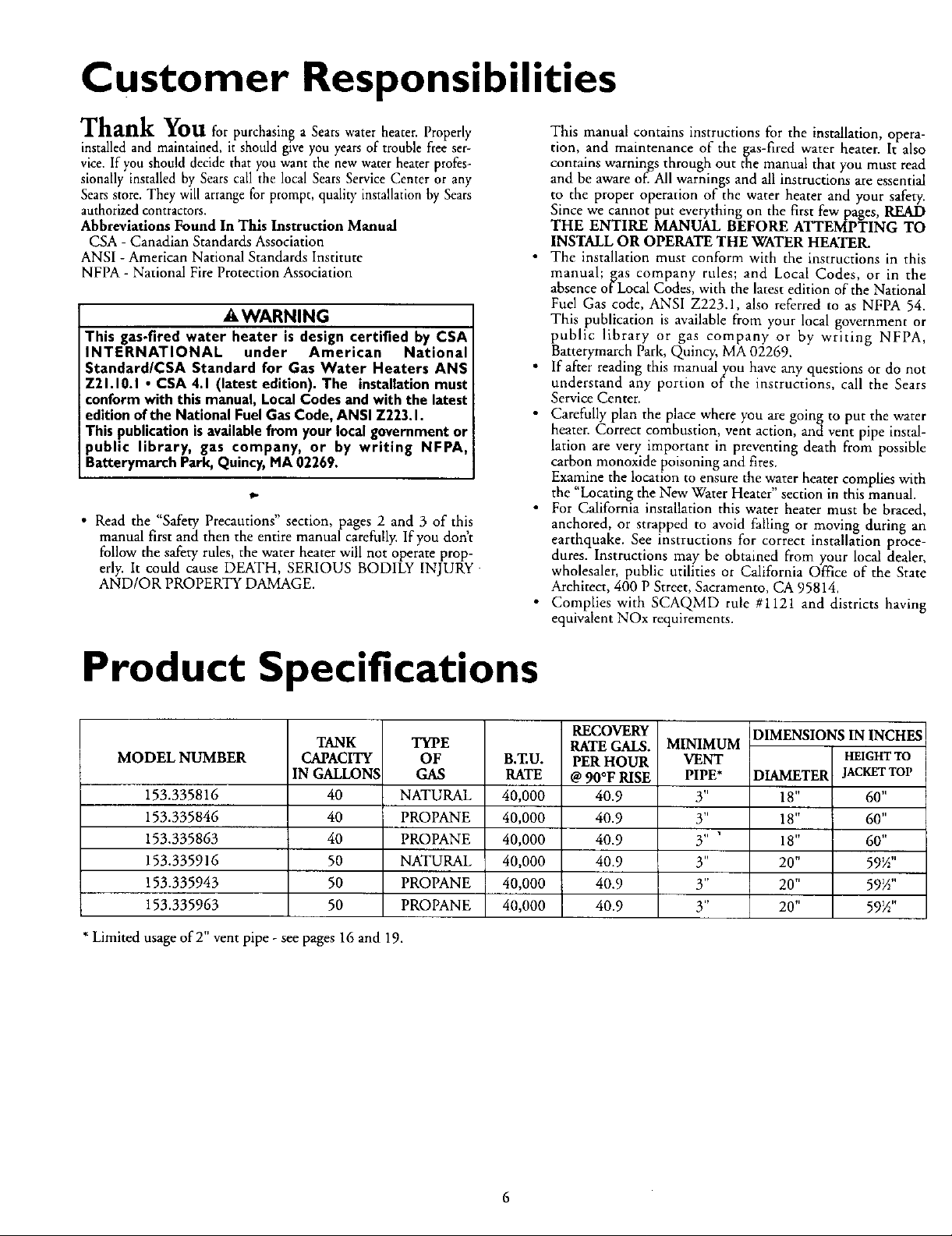
Product Specifications
TANK
MODEL NUMBER
CAPACITY
IN GALLONS
153.335816
153.335846
153.335863
153.335916
153.335943
153.335963
* Limited usage ofT' vent pipe - see pages 16 and 19.
40
40
40
50
50
50
TYPE
OF
GAS
NATURAL
PROPANE
PROPANE
NATURAL
PROPANE
PROPANE
B.ZU.
RATE
40,000
40,000
40,000
40,000
40,000
40,000
RECOVERY
RATE GALS.
PER HOUR
@ 90°F RISE
40.9
40.9
40.9
40.9
40.9
40.9
MINIMUM
VENT
PIPE*
3"
3"
3" '
y'
3"
3"
DIMENSIONS IN INCHES
HEIGHTTO
DIAMETER
18"
18"
18"
20"
20"
20"
JACKETTOP
60"
60"
60"
59_"
59_"
59V2"
6
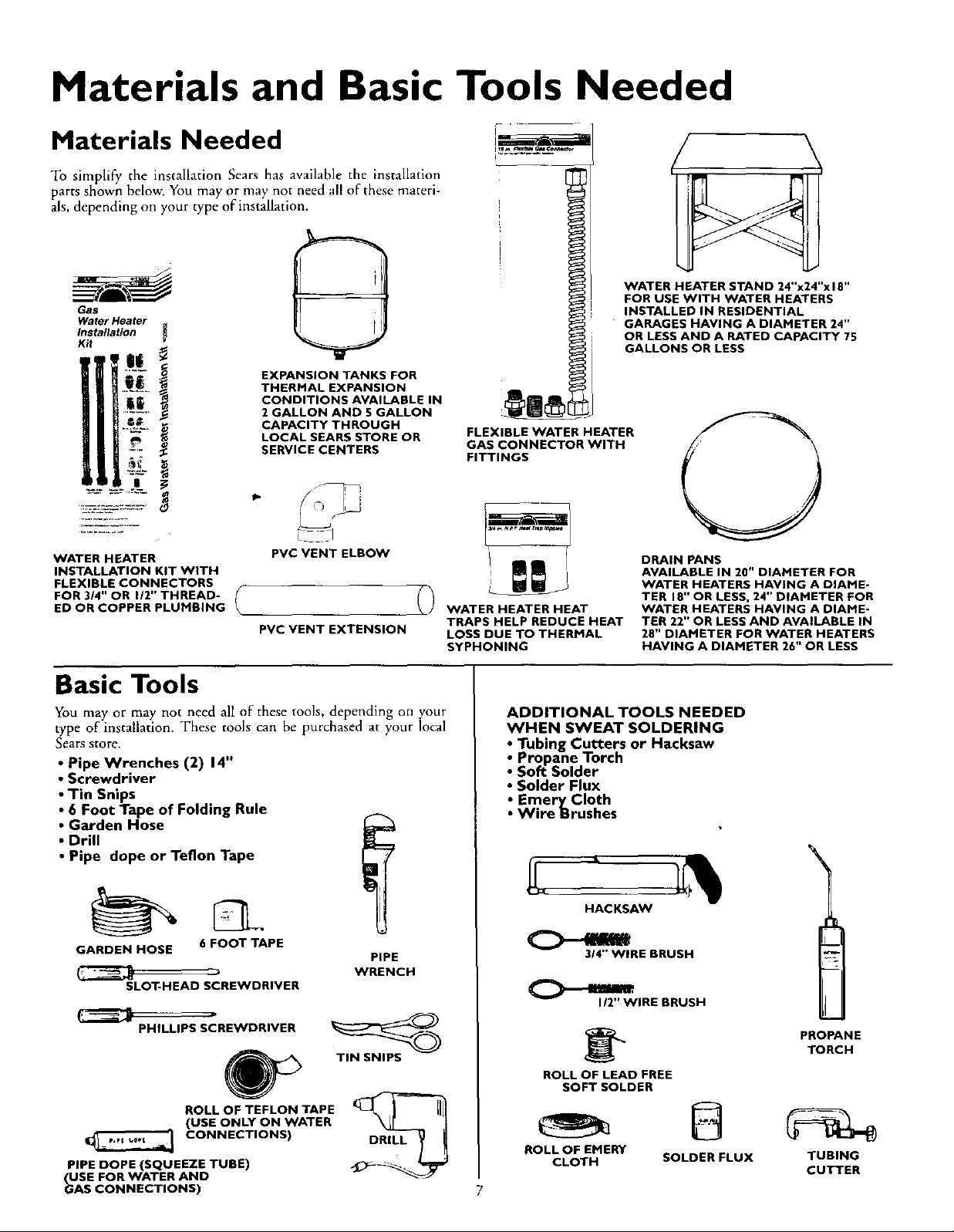
Materials and Basic Tools Needed
Materials Needed
To simplify the installation Sears has available the installation
parts shown below. You may or may not need all of these materi-
als, depending on your type of installation.
WATER HEATER STAND 24"x24"xlS"
Gas
Water Heater
Installation
K_t
EXPANSION TANKS FOR
THERMAL EXPANSION
CONDITIONS AVAILABLE IN
2 GALLON AND 5 GALLON
CAPACITY THROUGH
LOCAL SEARS STORE OR
SERVICE CENTERS
FLEXIBLE WATER HEATER
GAS CONNECTOR WITH
FITTINGS
FOR USE WITH WATER HEATERS
INSTALLED IN RESIDENTIAL
GARAGES HAVING A DIAMETER 24"
OR LESS AND A RATED CAPACITY 75
GALLONS OR LESS
O
WATER HEATER
INSTALLATION KIT WITH
FLEXIBLE CONNECTORS
FOR 3/4" OR I/2" THREAD-
ED OR COPPER PLUMBING
PVC VENT ELBOW
{ D
PVC VENT EXTENSION
Basic Tools
You may or may not need all of these tools, depending on your
type of installation. These tools can be purchased at your local
Searsstore.
• Pipe Wrenches (2) 14"
• Screwdriver
• Tin Snips
• 6 Foot Tape of Folding Rule
• Garden Hose
• Drill
• Pipe dope or Teflon Tape
GARDEN HOSE 6 FOOT TAPE
SLOT-HEAD SCREWDRIVER
PHILLIPS SCREWDRIVER
PIPE
WRENCH
TIN SNIPS
4P
ROLL OF TEFLON TAPE
(USE ONLY ON WATER
CONNECTIONS)
PIPE DOPE (SQUEEZE TUBE)
USE FOR WATER AND
_AS CONNECTIONS)
DRILL
WATER HEATER HEAT
TRAPS HELP REDUCE HEAT
LOSS DUE TO THERMAL
SYPHONING
ADDITIONAL TOOLS NEEDED
WHEN SWEAT SOLDERING
• Tubing Cutters or Hacksaw
• Propane Torch
• Soft Solder
• Solder Flux
• Emery Cloth
• Wire Brushes
HACKSAW
314" WIRE BRUSH
I/2" WIRE BRUSH
ROLL OF LEAD FREE
SOFT SOLDER
ROLL OF EMERY
CLOTH
DRAIN PANS
AVAILABLE IN 20" DIAMETER FOR
WATER HEATERS HAVING A DIAME-
TER 18" OR LESS, 24" DIAMETER FOR
WATER HEATERS HAVING A DIAME-
TER 22" OR LESS AND AVAILABLE IN
28" DIAMETER FOR WATER HEATERS
HAVING A DIAMETER 26" OR LESS
PROPANE
TORCH
@
SOLDER FLUX
TUBING
CUTTER
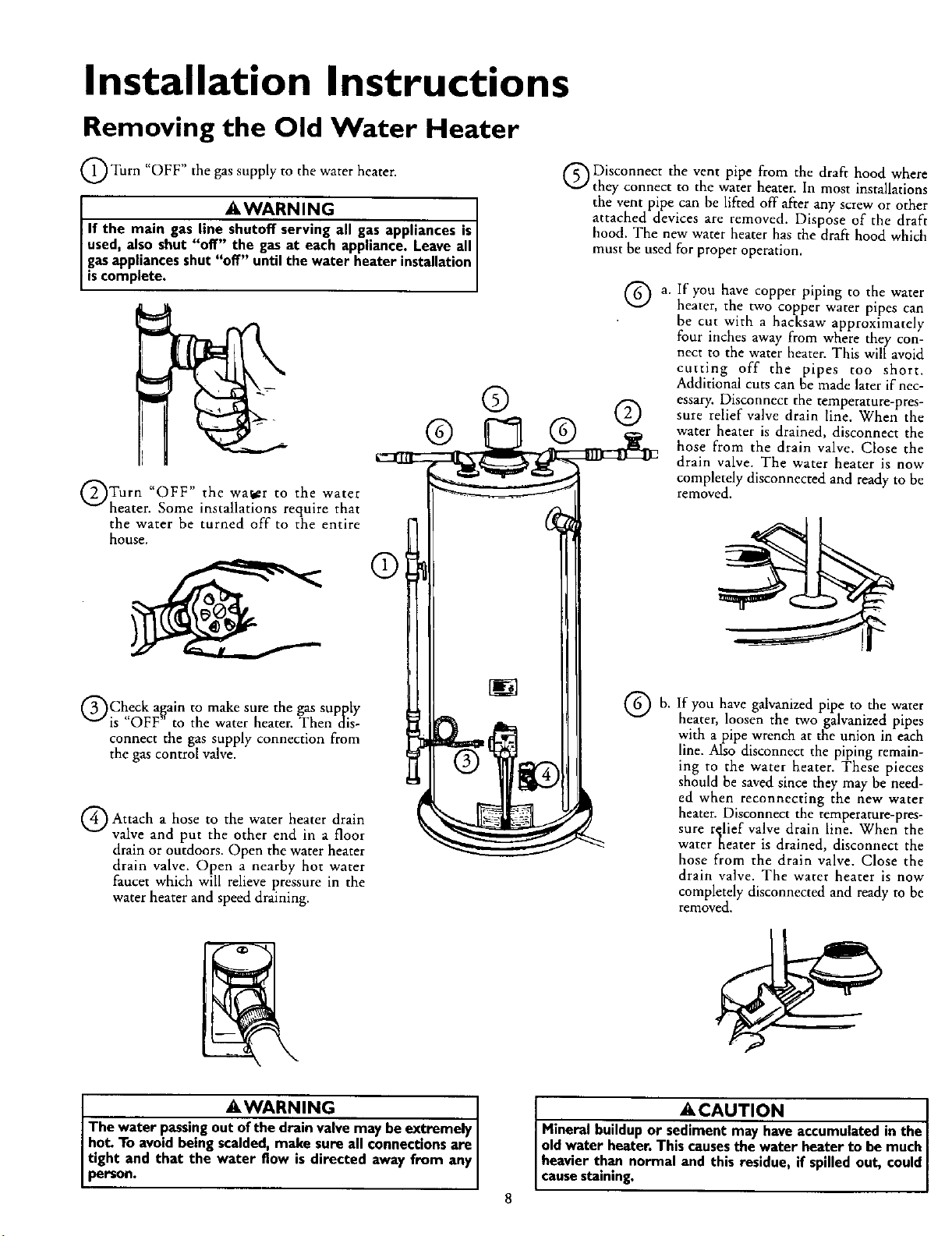
Installation Instructions
Removing the Old Water Heater
Q Turn gas supply to water
"OFF" the the heater.
_WARNING
If the main gas line shutoff serving all gas appliances is
used,also shut "off" the gasat each appliance.Leaveall
gasappliancesshut "off" until the water heater installation
iscomp ete.
QTurn water to water
"OFF" the the
heater. Some installations require that
the water be turned off to the entire
house.
®
Q Disconnect the vent pipe from the draft hood where
they connect to the water heater. In most installations
the vent pipe can be lifted off after any screw or other
attached devices are removed. Dispose of the draft
hood. The new water heater has the draft hood which
must be used for proper operation,
Q a. If you have copper piping to the water
® ®
heater, the two copper water pipes can
be cut with a hacksaw approximately
four inches away from where they con-
nect to the water heater. This will avoid
cutting off the pipes too short.
Additional cuts can he made later if nec-
essary. Disconnect the temperature-pres-
sure relief valve drain line. When the
water heater is drained, disconnect the
hose from the drain valve. Close the
drain valve. The water heater is now
completely disconnected and ready to be
removed.
QCheck again to make sure the gas supply
is "OFF" to the water heater. Then dis-
connect the gas supply connection from
the gas control valve.
Q Attach hose the heater drain
a to water
valve and put the other end in a floor
drain or outdoors. Open the water heater
drain valve. Open a nearby hot water
faucet which will relieve pressure in the
water heater and speed draining.
I AWARNING
The water passingou_ve may be extremely
hot. To avoidbeing scalded,make sure all connectionsare
tight and that the water flow is directed away from any
person.
If
G b. you galvanized pipe to water
have the
heater, loosen the two galvanized pipes
with a pipe wrench at the union in each
line. Also disconnect the piping remain-
ing to the water heater. These pieces
should be saved since they may be need-
ed when reconnecting the new water
heater. Disconnect the temperature-pres-
sure r_lief valve drain line. When the
water nearer is drained, disconnect the
hose from the drain valve. Close the
drain valve. The water heater is now
completely disconnected and ready to be
removed.
ACAUTION [
Mineral buildupor sediment may haveaccumulatedin the [
oldwater heater. This causesthe water heater to be much [
[ heavier than normal and this residue, if spilledout, could I
[ causestaining. ]
Installation Instructions
Locating the New Water
Heater
You should carefully choose an indoor location for the new water
heater, because the placement is a very important consideration
for the safety of the occupants in the building and for the most
economical use of the appliance. This water heater is not for
use in mobile homes or outdoor installation.
Whether replacing an old water heater or putting the water
heater in a new location, the following critical points must be
observed.
1. The location selected should be indoors as close as practical
to the vent termination point, and as centralized with the
water piping system as possible. The water heater, as all water
heaters, will eventually leak. Do not install without adequate
drainage provisions where water flow will cause damage.
2. If vented through an outside wall or through the roof the
vent piping cannot exceed a total of 35 feet including vertical
and horizontal runs and have no more than 3 elbows. It can-
not slope downward and horizontal runs require ¼" per foot
rise. All horizontal runs require adequate support at 3_ feet
intervals.
3. The water heater requires i_s own (separate) venting system.
It cannot be connected to an existing vent pipe or chimney.
It must terminate to the outdoors. Whenever possible termi-
nate the vent on the leaward side of the building if vented
through an outside wall. NOTE: Condensation may be cre-
ated, at times, as the combustion gases exit the vent cap
and discoloration of surfaces in proximity to the vent cap
may occur.
AWARNING
The powerventwater heaterrequires itsown(separate)venting
system.Itcannotbeconnectedto anexistingventpipeor chim-
ney.It mustbeterminatedto theoutdoors,Failureto pmperlyin-
stalltheventingsystemcanresultinasphyxiation,afireorexplo-
sionand can causeDEATH, SERIOUS BODILY INJURY,OR
PROPERTYDAMAGE.
4. The water hearer comes equipped with a 5 foot power cord
which can be used to connect to a 110/120 volt power
source if (1) local codes allow, and (2) there is a three prong
receptacle available.
A WARNING
Donot usean extensioncord.If there isnot a suitablerecepta-
cleand/or localcodesprohibituseof a powercord,fieldwiring
mustbeprovided.
ACAUTION
WATER HEATERS EVENTUALLY LEAK: Installation of the
water heater must be accomplished in such a manner that if
the tank or any connections should leak, the flow of water
will not cause damage to the structure. For this reason, it is
not advisable to install the water heater in at attic or upper
floor. When such locations cannot be avoided, a suitable
drain pan should be installed under the water heater. Drain
pans are available at your local Sears store. Such a drain pan
must be not greater than I% inches deep, have a minimum
length and width of at least 2 inches greater than the water
heater dimensions and must be piped to an adequate drain.
The pan must not restrict combustion air flow. Under no cir-
cumstances is the manufacturer or Sears to be held liable
for any water damage in connection with this water heater.
5. The location selection must provide adequate clearances for
servicing and proper operation of the water heater.
AWARNING
INSTALLATIONSIN AREASWHERE FLAMMABLELIQUIDS
(VAPORS) ARE LIKELY TO BE PRESENT OR STORED
(GARAGES, STORAGE, AND UTILITY AREAS, ETC):
Flammableliquids(suchas gasoline,solvents,propane(LP) or
butane, etc.), all of which emit flammable vapors,may be
improperlystoredor usedin suchareas.The gaswater heater
pilot lightor ma_nbumercanignitesuchvapors.The resulting
flashbackandfire cancausedeathor seriousburnsto anyonein
the area,aswellaspropertydamage.
Ifinstallationinsuchareasisyouronlyoption,thenthe installa-
tion must be accomplishedin a waythat the pilot flame and
mainburnerflameareelevatedfromthefloorat least18inches.
While this mayreducethechancesofflammablevaporsfroma
floorspillbeingignited,gasolineandotherflammablesubstances
shouldneverbestoredor usedin the sameroom or areacon-
tainingagaswater heateror otheropenflameor sparkproduc-
ingappliance.
NOTE: Flammablevaporsmaybe drawnby air currentsfrom
otherareasofthe structure to theappliance.
AWARNING
Propellantsofaerosolspraysand volatilecompounds,(clean-
ers,chlorinebasedchemicals,refrigerants, etc.)inadditionto
beinghighlyflammable in manycases,willalsochangeto cor-
rosive hydrochloricacid when exposedto the combustion
productsof the water heater.The results canbe hazardous,
andalsocauseproductfailure.
A WARNING
Thiswater heater mustnot be installeddirectlyon carpeting.
Carpeting must be protected by a metal or wood panel
beneath the applianceextendingbeyondthe full width and
depth of the appliance byat least3 inches(76.2mm) in any
direction,or if the applianceis installedin an alcoveorcloset,
the entire floor mustbe coveredby the panel.Failureto heed
this warningmayresultina firehazard.
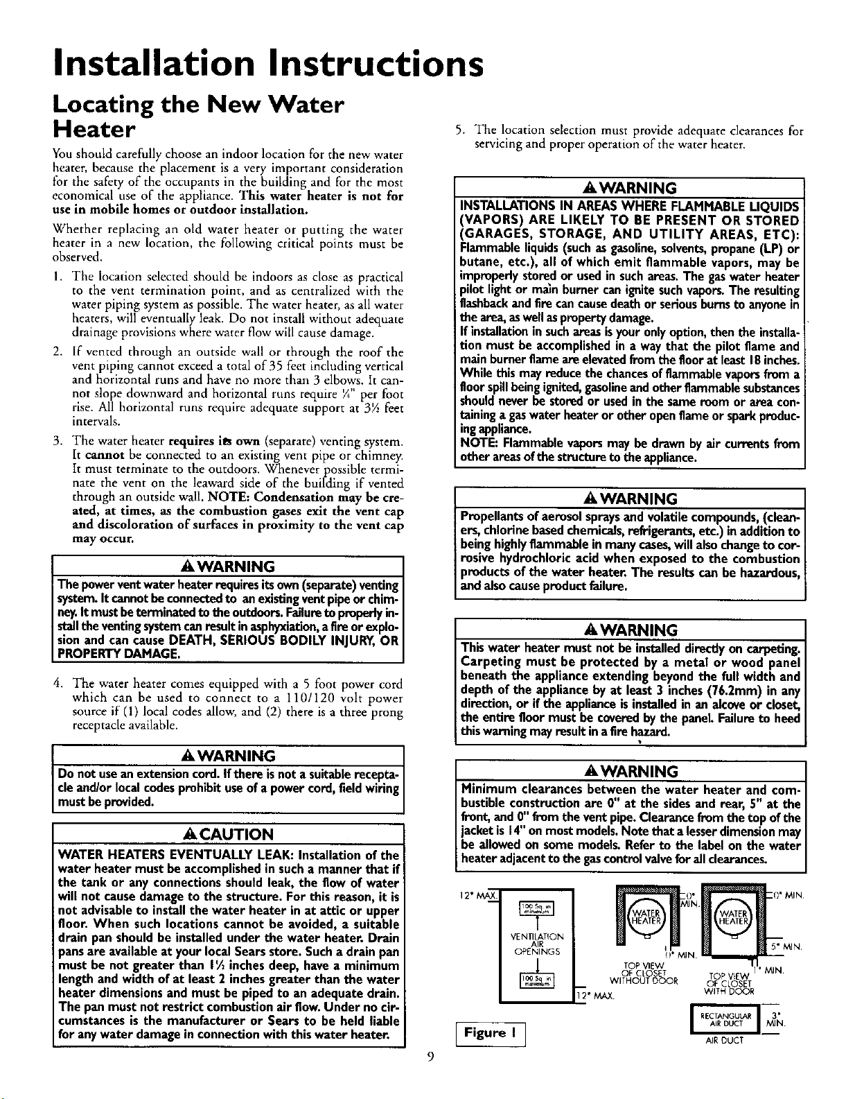
AWARNING
Minimum clearances between the water heater and com-
bustibleconstructionare 0" at the sidesand rear, 5" at the
front,and 0"fromthe vent pipe.Clearancefromthe top ofthe
jacketis 14"onmostmodels.Notethat a lesserdimensionmay
beallowedon somemodels.Referto the labelon the water
heateradjacentto the gascontrolvalveforallclearances.
12" MAX
Figure I ]
VENTILATION
AIR
OPENINGS
TOP VIEW 1 I
OF CLOSET TOP VIEW 1' MIN
WITHOUT OOOR OF CLOSET
'_2" MAX. WITH DOOR
_'_N [1' MIN
MIN'(!_MIN.
AlE DUCT
Installation Instructions (cont'd)
AWARNING
A gaswater heater cannot operate properly without the cor-
rect amount of air for combustion. Do not install in a con-
fined area such a closet, unless you provide air as shown in
the "Locating The New Water Heater" section. Never
obstruct the flow of ventilation air If you have any doubts or
questions at all, call your gascompany. Failure to provide the
proper amount of combustion air can result in a fire or explo-
sion and can cause DEATH, SERIOUS BODILY INJURY, OR
PROPERTY DAMAGE.
_iWARNING
If this water heater will be used in beauty shops, barber shops,
cleaning establishments, or self-service laundries with dry
cleaning equipment, it is imperative that the water heater or
water heaters be installed so that combustion and ventilation
air be taken from outside these areas. Refer to the "Locating
The New Water Heater" section of this manual and also the
latest edition of the National Fuel Gas Cede, ANSI Z223.1, also
referred to as NFPA 54 for specifics provided concerning air
required.
Combustion Air and Ventilation
When determining the installation location for apower vent
water heater, snow accumulation and drifting shouldbe consid-
ered in areas where applicable.
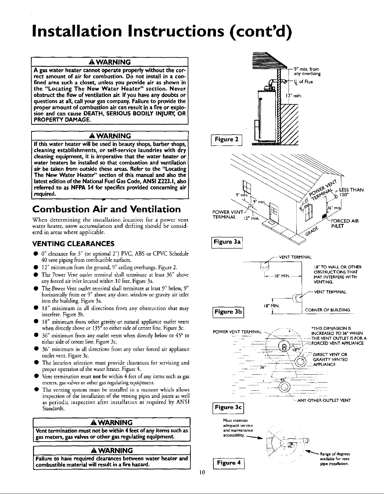
Figure 2 ]
TERMINAL 12" rain.
9"min. from
any overhang
-_. of Flue
12" min.
r
LESSTHAN
120"
FORCED AIR
INLET
VENTING CLEARANCES
• 0" clearance for Y (or optional 2") PVC, ABS or CPVC Schedule
40 vent piping from combustible surfaces,
• 12" minimum from the ground, 9" ceiling overhangs. Figure 2.
• The Power Vent outlet terminal shall terminate at least 36" above
any forced air inlet located within 10 feet. Figure 3a.
• The Power Vent outlet terminal shall terminate at least 9" below, 9"
horizontally from or 9" above any door, window or gravity air inlet
into the building. Figure 3a.
• 18" minimum in all directions from any obstruction that may
interfere. Figure 3b.
• 18" minimum from other gravity or natural appliance outlet vents
when directly above or 135° to either side of center line. Figure 3c.
• 36" minimum from any outlet vents when directly below or 45° to
either side of center line. Figure3c.
• 36" minimum in all directions from any other forced air appliance
outlet vent. Figure 3c.
• The location selection must provide clearances for servicing and
proper operation of the water heater. Figure 4.
• Vent termination must not be within 4 feet of any items such as gas
meters, gas valves or other gas regulating equipment.
• The venting system must be installed in a manner which allows
inspection of the installation of the venting pipes and joints as well
as periodic inspection after installation as required by ANSI
Standards.
li WARNING
Ventterminationmustnotbewithin4 feetofanyitemssuchas
gasmeters,gasvalvesor other gasregulating equipment,
li WARNING
Failureto haverequired clearancesbetweenwater heaterand
combustiblematerialwillresult ina firehazard.
IFigure 3a 1
f VENT TERMINAL
IE" TO WALL OR OTHER
_18" MIN. _
Figure 3b]
POWER VENT TERMINAL _ • "_ INCREASED TO 36" WHEN
-- - _ --, THE VENT OUTLET IS FOR A
-- _ ,RCED VENT APPLIANCE
.__ ---36" " _!
i
jf _ *THIS DIMENSION I$
-ANY OTHER OUTLET VENT
OBSTRUCTIONS THAT
MAY INTERFERE WITH
VENTING,
VENT TERMINAL
:ORNER OF BUILDING
- DIRECT VENT OR
GRAVITY VENTED
APPLIANCE
[F,gur c]
Must maintain
adequate service
and maintenance L
_cces$i_ili_
i Figure 4 I availableforvent
10
_i_i'_i__ ,,,
F_,_ .,-_ -_-_,
I L _ ril_'r '
pipe ins=llation.
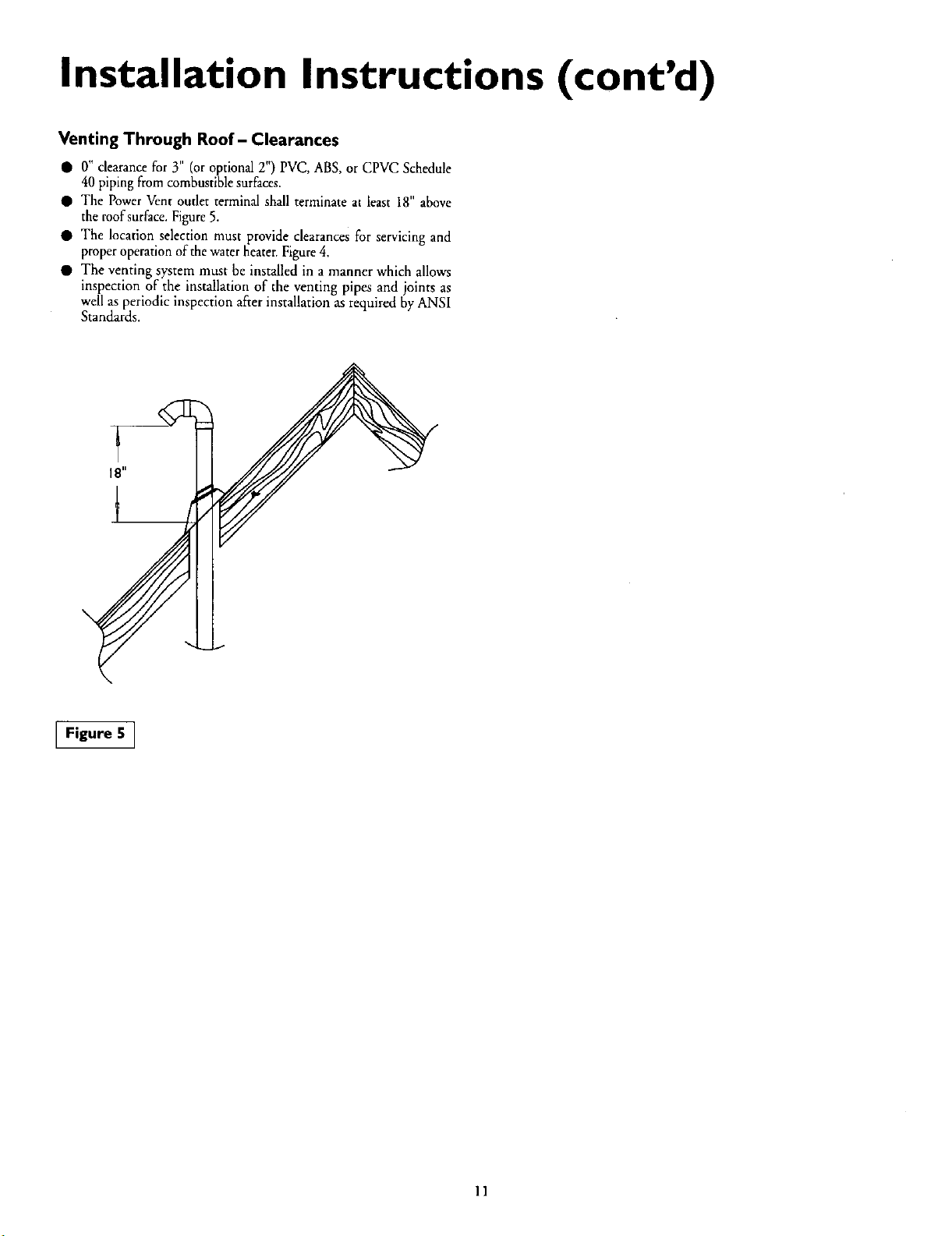
Installation Instructions (cont'd)
Venting Through Roof- Clearances
• 0" clearance for 3" (or optional 2") PVC, ABS, or CPVC Schedule
40 piping from combustible surfaces.
• The Power Vent outlet terminal shall terminate at least 18" above
the roof surface. Figure 5.
• The location selection must provide clearances for servicing and
properoperationof thewaterheater. Figure4,
• The venting system must be installed in a manner which allows
inspection of the installation of the venting pipes and joints as
well as periodic inspection after installation asrequired by ANSI
Standards.
18"
Figure 5_
11
Installation Instructions (cont'd)
Combustion Air and Ventilation
for Appliances Located in
Unconfined Spaces
Unconfined Space is a space whose volume is not less than 50 cubic
feet per 1,000 Btu per hour of the aggregate input rating of all appli-
ances installed in that space. Rooms communicating directly with the
space in which the appliances are installed, through openings not fur-
nished with doors, are considered a part of the unconfined space.
In unconfined spaces in buildings, infiltration may be adequate to
provide air for combustion, ventilation and dilution of flue gases.
However, in buildings of tight construction (for example, weather
stripping, heavily insuhted, caulked, vapor barrier, etc.), additional air
may need to be provided using the methods described in Combustion
Air and Ventilation for Appliances Located in Confined Spaces.
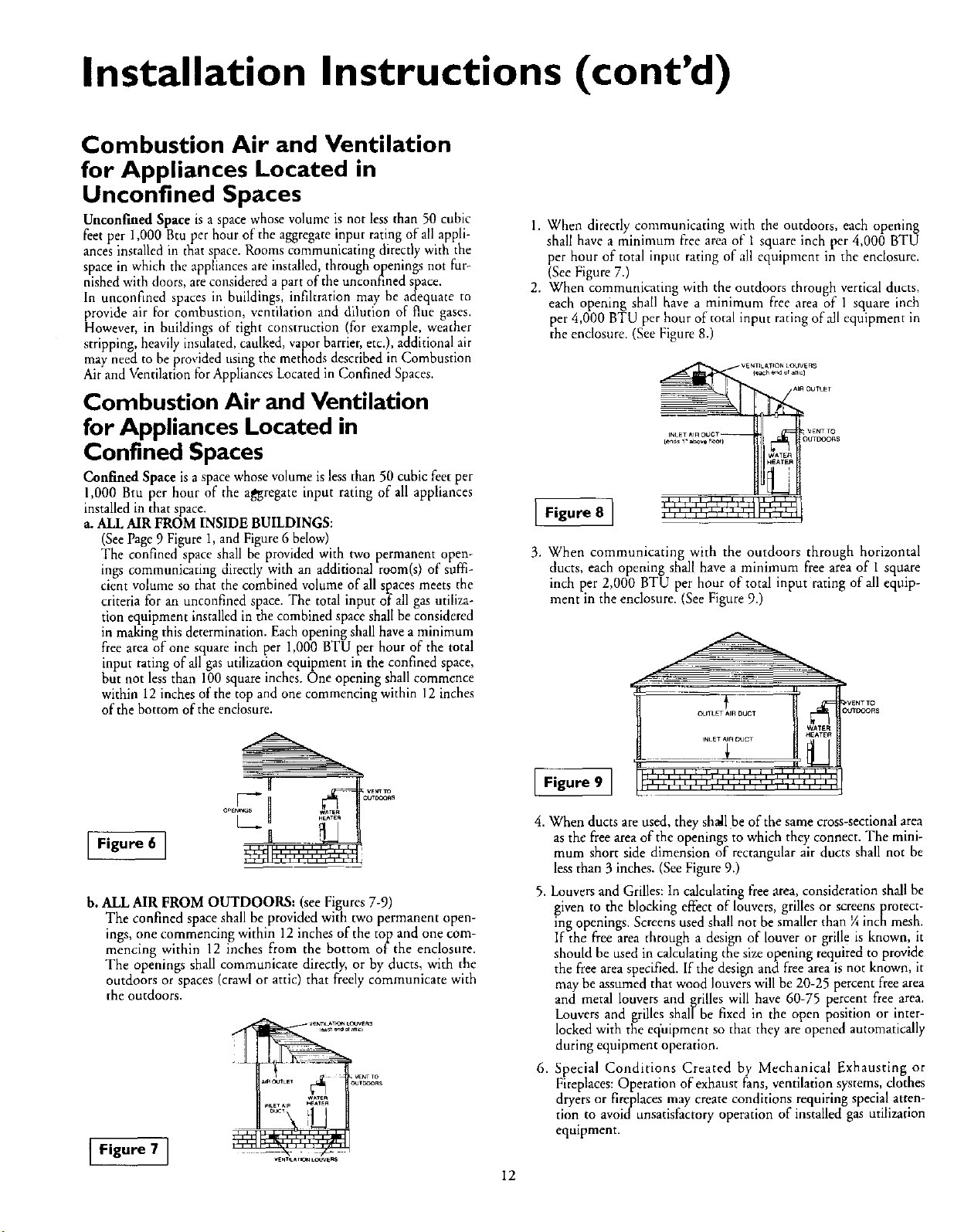
Combustion Air and Ventilation
1. When directly communicating with the outdoors, each opening
shall have a minimum free area of 1 square inch per 4,000 BTU
per hour of total input rating of all equipment in the enclosure.
(See Figure 7.)
2. When communicating with the outdoors through vertical ducts,
each opening shall have a minimum flee area of 1 square inch
per 4,000 BTU per hour of total input rating of all equipment in
the endosure. (See Figure 8.)
vEr_TKAhON LOUVERS
4each er_ or amc]
AIR OUTLET
for Appliances Located in
Confined Spaces
Confined Space is a space whose volume is less than 50 cubic feet per
1,000 Btu per hour of the a_regate input rating of all appliances
installed in that space.
a. ALL AIR FROM INSIDE BUILDINGS:
(See Page 9 Figure 1, and Figure 6 below)
The confined space shall be provided with two permanent open-
ings communicating directly with an additional room(s) of suffi-
cient volume so that the combined volume of all spaces meets the
criteria for an unconfined space. The total input of all gas utiliza-
tion equipment installed in the combined space shall be considered
in making this determination. Each opening shall have a minimum
free area of one square inch per 1,000 BTU per hour of the total
input rating of all gas utilization equipment in the confined space,
but not less than 100 square inches. One opening shall commence
within 12 inches of the top and one commencing within 12 inches
of the bottom of the enclosure.
_ VEr_Tm
,o.....
J Figure 6 J
b. ALL AIR FROM OUTDOORS: (see Figures 7-9)
The confined space shall be provided with two permanent open-
ings, one commencing within 12 inches of the top and one com-
mencing within 12 inches from the bottom of the enclosure.
The openings shall communicate directly, or by ducts, with the
outdoors or spaces (crawl or attic) that freely communicate with
the outdoors.
Figure 7 ]
Figure 8 ]
{ends 1, a_e _le,00
i i i i i i i i i I I
I I I I I llliJik I I_1_
WATE¢_
H_ATER
3. When communicating with the outdoors through horizontal
ducts, each opening shall have a minimum flee area of 1 square
inch per 2,000 BTU per hour of total input rating of all equip-
ment in the enclosure. (SeeFigure 9.)
OUTLET AIR DUCT Ol/TP'_OFI$
tNLE
Figure 9 ]
4. When ducts are used, they shatl be of the same cross-sectional area
as the free area of the openings to which they connect. The mini-
mum short side dimension of rectangular air ducts shall not be
less than 3 inches. (See Figure 9.)
5. Louvers and Grilles: In calculating free area, consideration shall be
given to the blocking effect of louvers, grilles or screens protect-
ing openings. Screens used shall not be smaller than ¼ inch mesh.
If the free area through a design of louver or grille is known, it
should be used in calculating the size opening required to provide
the free area specified. If the design and free area is not known, it
may be assumed that wood louvers will be 20-25 percent free area
and metal louvers and grilles will have 60-75 percent free area.
Louvers and grilles shall be fixed in the open position or inter-
locked with the equipment so that they are opened automatically
during equipment operation.
6. Special Conditions Created by Mechanical Exhausting or
Fireplaces: Operation of exhaust Fans, ventilation systems, clothes
dryers or fireplaces may create conditions requiring special atten-
tion to avokl unsatisfactory operation of installed gas utilization
equipment.
I2
illllllllllll'l'l'l ' _'_l_l_II
WATER
Installation Instructions (cont'd)
Water Piping
AWARNING
HOTTERWATERCAN SCALD:Water heatersareintendedto
)reducehot water.Water heatedto a temperaturewhichwill
satisfyclotheswashing,dishwashing,andothersanitizingneeds
canscaldandpermanently iniureyou uponcontact.Somepeo-
)leare more likelyto bepermanentlyinjuredby hotwaterthan
others.Theseincludethe elderly,children,theinfirm,orphysical-
ly/mentallyhandicapped.Ifanyoneusinghotwaterinyour home
fits into oneofthesegroupsor if there is alocalcode or state law
requiringa certaintemperature waterat the hot water tap, then
_)umusttakespecialprecautions.Inadditionto usingthelowest
_ossibletemperaturesettingthatsatisfiesyourhotwaterneeds,
a meanssuchasa mixingvalve,shouldbe usedat thehotwater
tapsusedbythesepeopleor at the water heater.Mixingvalves
areavailableat plumbingsupplyor hardwarestores.Followman-
ufacturersinstructions for installation of the valves. Before
changing the factory setting on the thermostat, read the
"TemperatureRegulation"sectioninthismanual.
This water heater shall nor be connected to any heating systems
or component(s) used with a non-potable water hearing appli-
2d_ce.
If a water heater is installed in a closed water supply system;
such as one having a back-flow preventer, check valve, water
meter with a check valve, etc.., in the cold water supply; means
shall be provided to control thermal expansion. Contact the
local utility or local Sears Service Center on how to control this
situation.
NOTE: To rotect against untimely corrosion of hot and
cold water _ it is strongly recommended that dielec-
tric unions or couplings be installed on this water heater
when connected to copper pipe.
tings,
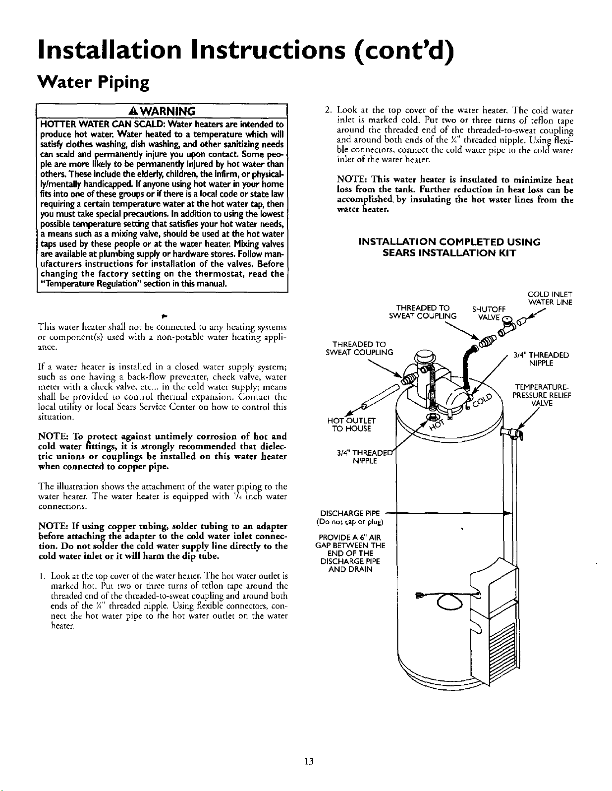
2. Look at the top cover of the water heater. The cold water
inlet is marked cold. Put two or three turns of teflon tape
around the threaded end of the threaded-to-sweat coupling
and around both ends of the _" threaded nipple. Using flexi-
ble connectors, connect the cold water pipe to the coldwater
inlet of the water heater.
NOTE: This water heater is insulated to minimize heat
loss from the tank. Further reduction in heat loss can be
accomplished by insulating the hot water lines from the
water heater.
INSTALLATION COMPLETED USING
SEARS INSTALLATION KIT
COLD INLET
WATER LINE
3/4" THREADED
NIPPLE
TEMPERATURE-
PRESSURERELIEF
VALVE
THREADED TO
SWEAT COUPLING
HOT OUTLET
TO HOUSE
3/4" THREADED'
NIPPLE
THREADED TO SHUTOFF
SWEAT COUPLING
The illustration shows the attachment of the water piping to the
water heater. The water heater is equipped with 74 inch water
connections.
NOTE: If using copper tubing, solder tubing to an adapter
before attaching the adapter to the cold water inlet connec-
tion. Do not solder the cold water supply line directly to the
cold water inlet or it will harm the dip tube.
1. Look at the top cover of the water heater. The hot water outlet is
marked hot. Put two or three turns of teflon tape around the
threaded end of the threaded-to-sweat coupling and around both
ends of the ¼" threaded nipple. Using flexible connectors, con-
nect the hot water pipe to the hot water outlet on the water
heater.
DISCHARGE PIPE
(Do not cap or plug)
PROVIDE A 6" AIR
GAP BETWEEN THE
END OF THE
DISCHARGE PIPE
AND DRAIN
13
Installation Instructions (cont'd)
Temperature-Pressure Relief Valve
_,WARNING
_-- AWARNING
At the time of manufacturethiswater heater wasprovided
with a combinationtemperature-pressuresrelief valvecertified
bya nationallyrecognizedtestinglaboratory that maintains
periodicinspectionofproductionoflistedequi.p,ment or mate-
rials, as meeting the requirements for Rehef Valves and
AutomaticGasShutoffDevicesforHot Water SupplySystems,
andthe latest editionof ANSI Z21.22and the code require.
ments ofASME. If replaced,the valvemustmeet the require.
ments oflocalcodes,butnot lessthana combinationtempera-
ture and pressure reliefvalvecertifiedasmeetingthe require-
mentsfor ReliefValvesandAutomaticGasShutoffDevicesfor
Hot Water SupplySystems,ANSI Z21.22bya nationally recog-
nized testinglaboratorythat maintains periodicinspectionof
productionoflistedequipmentor materials.
hevalvemust be markedwith a maximumset pressurenot
to exceed the marked hydrostaticworking pressureof the
water heater(150 Ibs./sq.in,)anda dischargecapacitynot less
thanthe water heaterinputrate asshownon the modelrating
plate. (Electric heaters- watts dividedby 1000x 3415 equal
BTU/Hr.rate.) _.
Yourlocaljurisdictionalauthority,whilemandatingthe useofa
temperature-pressurerelief valvecomplyingwithANSI Z21.22
and ASME, may require a valvemodeldifferentfrom the one
furnishedwiththe water heater.
Compliancewith suchlocalrequirements mustbe satisfiedby
the installeror enduserofthewater heaterwith a locallypre-
scribedtemperature-pressurereliefvalveinstalledinthe desig-
nated openingin the water heaterin placeof the factoryfur-
nishedvalve.
Forsafeoperationofthewaterheater,the relief valvemustnot
beremovedfrom it'sdesignatedopeningor plugged,
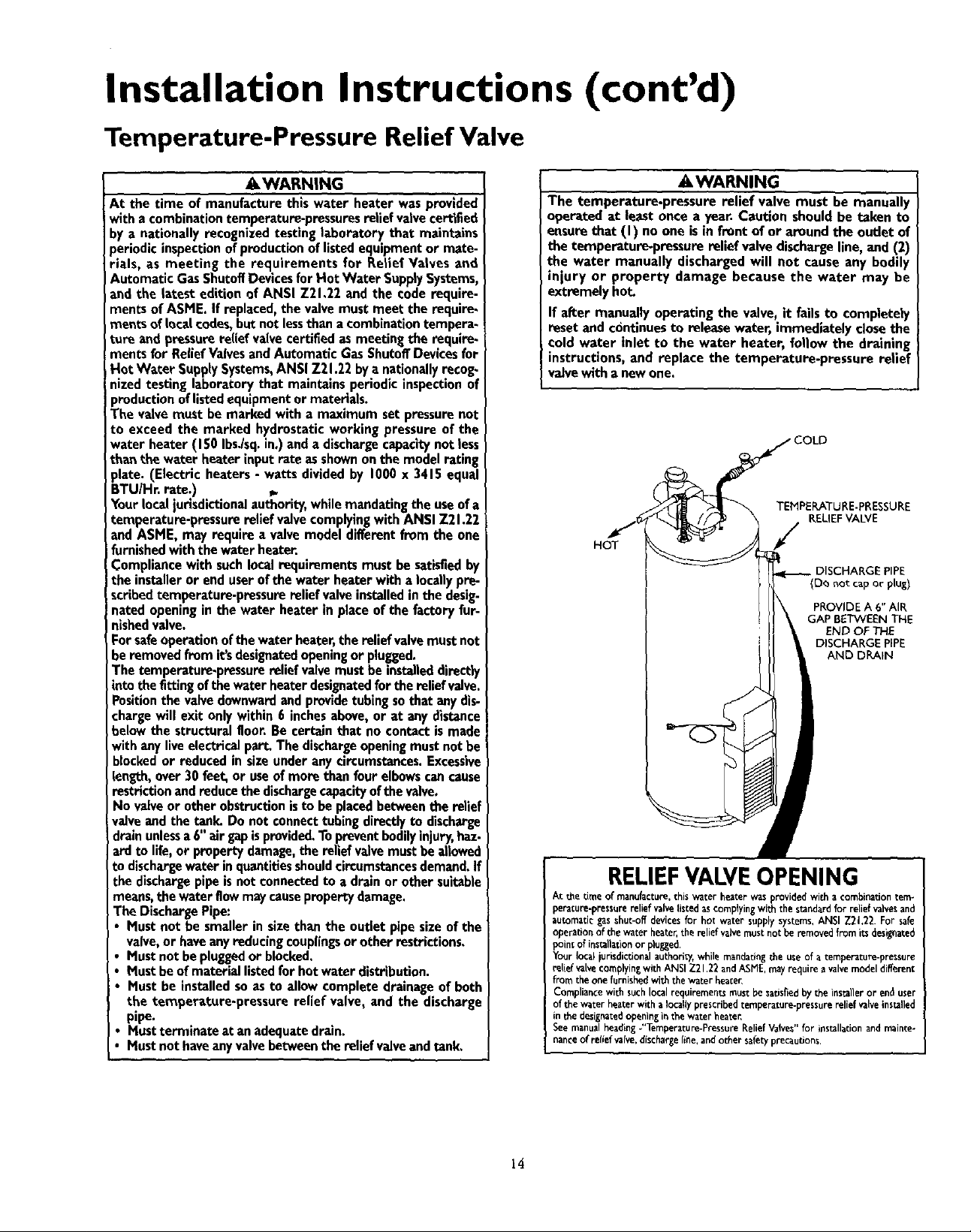
The temperature-pressurereliefvalvemust be installeddirectly
intothe fittingofthe water heaterdesignatedforthe relief valve.
Positionthe valvedownwardandprovidetubingsothatanydis-
chargewill exit onlywithin6 inchesabove,or at any distance
belowthe structuralfloor.Be certainthat no contactismade
withany liveelectricalpart.The dischargeopeningmustnot be
blockedor reduced in sizeunderanycircumstances.Excessive
length, over 30 feet,or useof more thanfour elbowscancause
restriction andreducethe dischargecapacityofthe valve.
No valveor other obstructionisto beplacedbetweentherelief
valveandthe tank.Do not connecttubingdirectlyto discharge
drainunlessa6" airgapisprovided.Topreventbodilyinjury,haz-
ardto life,or propertydamage,the relief valvemustbeallowed
to dischargewaterinquantitiesshouldcircumstancesdemand.If
thedischargepipe isnot connectedto a drainor othersuitable
means,thewaterflowmaycausepropertydamage.
The DischargePipe:
Mustnot be smallerin sizethanthe outletpipesizeof the
I" valve,or haveanyreducingcouplingsor other restrictions.
Mustnot be pluggedorblocked.
Mustbeofmateriallistedforhotwater distribution.
Mustbe installedsoasto allowcomplete drainageof both
the temperature-pressurerelief valve, and the discharge
pipe.
Mustterminateat anadequatedrain.
Mustnothaveanyvalvebetweenthe relief valveandtank,
The temperature.pressure relief valve must be manually
operated at leastonce a year.Caution shouldbe taken to
ensurethat (I) no one isin frontof or aroundthe outlet of
the temperature-pressurerelief valvedischargeline,and (2)
the water manually dischargedwill not causeany bodily
injury or property damage because the water may be
extremelyhot.
If after manually operatingthe valve,it failsto completely
reset and continuesto releasewater, immediatelyclosethe
coldwater inlet to the water heater, follow the draining
instructions,and replace the temperature-pressure relief
valvewitha newone.
HOT
RELIEFVALVEOPENING
At the tir_e of manufacture, this water heater was provided with a combination tem-
perature-pressurerelief valve listedas complying with the standard for relief valvesand
automatic gas shut-off devices for hot water supply systems, ANSI Z21.22. For safe
operationofthe waterheater,the reliefvalvemustnot beremovedfromitsdesignated
point of installationor plugged.
Your local jurisdictionalauthority,while mandating the use of a temperature-pressure
relle_valve complyinZwith ANSI 721.22 and ASME,may require avalve model different
fromthe onefurnishedwiththewaterheater,
Compliancewithsuchlocalrequirementsmustbesatisfiedbytheinstalleror enduser
of the water heater with a locallyprescribedtemperature-pressure relief valveinstalled
in the designatedopeningin the water beater
See manual headingJ'Temperature-PressureRelief Valves" for installationand mainte-
nance of relief valve,dischargeline, and other safety precautions.
TEMPERATURE-PRESSURE
RELIEFVALVE
/
• DISCHARGE PIPE
{D_ r_otcap or plus)
PROVIDE A 6" AIR
GAP BETWEEN THE
END OF THE
DISCHARGE PiPE
AND DRAIN
14
 Loading...