

Kenmore 153.335942, 153.335845, 153.335816, 153.335842, 153.335862 Owner's Manual
...
Owners
Manual
FOR POTABLEWATER
HEATING ONLY
NOT SUITABLEFOR
SPACEHEATING
NOT FOR USE IN
MOBILE HOMES
Model No.
L53.335816 40 Gal.
153.335845 40 Gal. High Altitude L.R
153.335862 40 GaL.L.R
153.335916 50 Gal.
153.335942 50 Gal. High Altitude L.R
153.335962 50 Gal. L.R
Caution:
Read and Follow
All Safety Rules and
Operating Instructions
Before First Use of
This Product.
Save this Manual for Future Reference.
POWER MISER TM 9
POWER VENT
GAS WATER HEATER
• Safety Instructions • Care and Maintenance
• Installation • Troubleshooting
• Operation • Parts List
For Your Safety
AN ODORANT IS ADDED TO THE GAS USED BY THIS
WATER HEATER
WARNING: If the information in these instructions are not fol-
lowed exactly, a fire or explosion may result, causing property
damage, personal injury or death•
____Donot store or use gasoline or other flammable vapors and liq-
uids in the vicinity of this or any other appliance•
_-_/VHAT TO DO IF YOU SMELL GAS
_-=" Do not try to light any appliance.
• Do not touch any electrical switch; do not use any phone in your
building.
• • * 9
o-- Immediately call your gas supplier from a neighbor s phone.
Follow the gas supplier's]nstructions.
-_r If you can not reach your gas suppher, call the fire department.
--Installation and service must be performed by a qualified installer,
serv,ce agency or the gas suppher.
AWARNING
Improper installation, adjustment, alteration, service or maintenance
can cause DEATH, SERIOUS BODILY INJURY, OR PROPERTY DAM-
AGE. Refer to this manual for assistance or consult the local Sears
LService Center or gas uti ty for further nformat on.
•,WARNING t
Flammable vapors may be drawn by air currents from other areas
of the structure to this appliance.
_WARNING
READ THE GENERAL SAFETY SECTION BEGINNING ON INSIDE
COVER AND THEN THIS ENTIRE MANUAL BEFORE INSTALLING
OR OPERATING THIS WATER HEATER.
Sears, Roebuck and Co., Hoffman Estates, IL 60179 U.S.A.
Safety Precautions
&`WARNIN__G
Improper installation, adjustment, alteration, service or
maintenance can cause death, serious bodily injury, or
property damage. Refer to this manual for assistance or
consult your local Sears Service Center for further
I information.
_,WARNING
WATER HEATERS EQUIPPED FOR ONE TYPE GAS
ONLY: This water heater is equipped for one type gas
only. Check the model rating plate near the gas control
valve for the correct gas. DO NOT USE THIS WATER
HEATER WITH ANY GAS OTHER THAN THE ONE
SHOWN ON THE MODEL RATING PLATE. Failure to
use the correct gas can cause problems which can result in
DEATH, SERIOUS BODILY INJURY, OR PROPERTY
;)AMAGE. If you have any questions or doubts consult
four gas supplier or local utility.
&`WARNING
INSTALLATIONS IN AREAS WHERE FLAMMABLE LIQ-
UIDS (VAPORS) ARE LIKELY TO BE PRESENT OR
STORED (GARAGES, STORAGE, AND UTILITY AREAS
ETC): Flammable liquids (such as gasoline, solvents
propane(LP) or butane, etc.), all of which emit flammable
vapors, may be improperly stored or used in such areas.
The gaswater heater pilot light or mainburner can ignite
such vapors. The resulting flashback and fire can cause
death or serious burns to anyone in the area, as well as
property damage.
If installation in such areas is your only option, then the
installation must be accomplishedin a way that the pilot
flame and main burner flame are elevated from the floor
at least 18 inches.While this may reduce the chancesof
flammable vapors from a floor spill beingignited, gasoline
and other flammable substancesshouldnever be storedor
used in the same room or area containing a gas water
heater or other open flame or sparkproducingappliance.
qOTE: Flammable vapors may be drawn by air currents
from other areas of the structureto the appliance.
&`WARNING
f this water heater will be used in beauty shops, barber
shops, cleaning establishments, or self-service laundries
with dry cleaning equipment, it is imperative that the
water heater or water heaters be installed so that com-
bustion and ventilation air be taken from outside these
areas. Refer to the "Locating The New Water Heater"
section of this manual and also the latest edition of the
National Fuel Gas Code, ANSI Z223.1, also referred to as
NFPA 54 for specifics provided concerning air required.
&`WARNING
A fire can start if combustible materials such as clothing, I
cleaning materials, or flammable liquids are placed against
or next to the water heater.
&,WARNING
At the time of manufacture this water heater was provid-
ed with a combination temperature-pressures relief valve
certified by a nationally recognized testing laboratory
that maintains periodic inspection of production of listed
equipment or materials, as meeting the requirements
for Relief Valves and Automatic Gas Shutoff Devices for
Hot Water Supply Systems, and the latest edition of
ANSI Z21.22 and the code requirements of ASME. If
replaced, the valve must meet the requirements of local
codes, but not less than a combination temperature and
pressure relief valve certified as meeting the require-
ments for Relief Valves and Automatic Gas Shutoff
Devices for Hot Water Supply Systems, ANSI Z21.22 by
a nationally recognized testing laboratory that maintains
periodic inspection of production of listed equipment or
materials.
The valve must be marked with a maximum set pressure
not to exceed the marked hydrostatic working pressure
of the water heater (150 Ibs./sq. in.) and a discharge
capacity not |ess than the water heater input rate as
shown on the model rating plate. (Electric heaters -
watts divided by 1000 x 3415 equal BTU/Hr. rate.)
Your local jurisdictional authority, while mandating the
use of a temperature-pressure relief valve complying
with ANSI Z21.22 and ASME, may require a valve model
different from the one furnished with the water heater.
Compliance with such local requirements must be satis-
fied by the installer or end user of the water heater with
a locally prescribed temperature-pressure relief valve
installed in the designated opening in the water heater in
place of the factory furnished valve.
For safe operation of the water heater, the refief valve
must not be removed from it's designated opening or
plugged.
The temperature-pressure relief valve must be i_t_lled
directly into the fitting of the water heater _ignated
for the relief valve. Position tee valve nuw,w_:J_and pro.
vide tubing so that any discharg_ will exit only _vithin I
inches above, or at any distance below the s_ructura
floor. Be certain that no c_itl_any live
electrical part. The discharge oF_r_ust not be
blocked or reduced in sli_n-d'eP'a_fe_nstances.
Excessive length, over 30 feef;_J: sOJL_,_____. than four
elbows can cause restriction and redu_e_discharge
capacity of the valve. - .... ,
No valve or other obstruction is to be placed_between
the relief valve and the tank::l_-m_mne'_t tubing
directly to discharge drain unless a 6" air gap is provided.
To prevent bodily injury, hazard to life, or property dam-
age, the relief valve must be allowed to discharge water
in quantities should circumstances demand. If the dis-
charge pipe is not connected to a drain or other suitable
means, the water flow may cause property damage.
The Discharge Pipe:
• Must not be smaller in size than the outlet pipe size of
the valve, or have any reducing couplings or other
restrictions.
• Must not be plugged or blocked.
• Must be of material listed for hot water distribution.
• Must be installed so as to allow complete drainage of
bothdischargethe temperature-pressurepipe.relief valve, and the
Must terminate at an adequate drain.
Must not have any valve between the relief valve and
tank.
Safety Precautions
AWARNING
A gas water heater cannot operate properly without the
correct amount of air for combustion. Do not install in a
confined area such a closet, unless you provide air as
shown in the "Locating The New Water Heater" section.
Never obstruct the flow of ventilation air. If you have any
i doubts or questions at all call your gas company. Failure
to provide the proper amount of combustion air can result
in a fire or explosion and can cause DEATH, SERIOUS
BODILY INJURY, OR PROPERTY DAMAGE.
AWARNING
This water heater must not be installed directly on car-
peting. Carpeting must be protected by a metal or wood
panel beneath the appliance extending beyond the full
width and depth of the appliance by at least 3 inches
(76.2mm) in any direction, or if the appliance is installed
in an alcove or closet, the entire floor must be covered by
the panel. Failure to heed this warning may result in a
fire hazard.
AWARNING
HOTTER WATER CAN SCALD: Water heaters are
intended to produce hot water. Water heated to a tern-
perature which will satisfy clothes washing, dish washing,
and other sanitizing needs can scald and permanently
injure you upon contact. Some people are more likely to
be permanently injured by hot water than others. These
include the elderly, children, the infirm, or physically/men-
tally handicapped. If anyone using hot water in your home
fits into one of these groups or if there is a local code or
state law requiring a certain temperature water at the hot
water tap, then you must take special precautions. In addi-
tion to using the lowest possible temperature setting that
satisfies your hot water needs, a means such as a mixing
valve, should be used at the hot water taps used by these
people or at the water heater. Mixing valves are available
at plumbing supply or hardware stores. Follow manufac-
turers instructions for installation of the valves. Before
changing the factory setting on the thermostat, read the
"Temperature Regulation" section in this manual.
_,WARNING
Soot build-up indicates a problem that requires correc-
tion before further use. Turn "off" gas to water heater
and leave "off" until repairs are made, because failure to
correct the cause of the sooting can result in a fire or
explosion causing DEATH, SERIOUS BODILY INJURY,
OR PROPERTY DAMAGE.
_,WARNING
The power vent water heater requires its own (separate)
venting system. It cannot be connected to an existing vent
pipe or chimney. It must be terminated horizontally to the
outdoors. Failure to properly install the venting system can
result in asphyxiation, a fire or explosion and can cause
DEATH, SERIOUS BODILY INJUR_, OR PROPERTY DAM-
AGE.
&WARNING
No vent damper installation is compatible with this power
vented water heater design. No vent damper, whether it is
operated thermally or otherwise is to be installed on this
power vented w=ter heater. Alteration of any part of the fac-
, tory-furnished vent assembly could result in improper oper-
ation due to restriction of flue gases, spillage of flue gases
and may cause carbon monoxide poisoning.
_,WARNING
,The appliance and its individualshutoff valve mustbe dis-
connectedfrom the gassupplypipingsystem during any
pressure testing of the gassystem at test pressuresin
excessof I/2 poundper squareinch(3.5kPa).
• The appliance must be isolatedfrom the gassupplypip-
ing system by closingits individualmanual shutoff valve
during any pressuretesting of the gassupplypiping sys-
tem at test pressuresequal or lessthan I/2 pound per
squareinch (3.5kPa).
AWARNING
BEFORE LIGHTING [PROPANE (L.P.) GAS WATER
HEATERS]: Propane (L.R) gas is heavier than air. Should
there be a leak in the system, the gas will settle near the
ground. Basements, crawl spaces, skirted areas under
mobile homes (even when ventilated), closets and areas
below ground level will serve as pockets for the accumula-
tion of this gas. Before attempting to light or relight the
water heater's pilot or turning on a nearby electrical light
switch, be absolutely sure there is no accumulated gas in
the area. Search for odor of gas by sniffing at ground level
in the vicinity of the appliance. If odor is detected, follow
steps indicated at "For Your Safety" on the cover page of
:his manual then leave the premises.
AWARNING
Chemical vapor corrosion of the flue and vent system
may occur if air for combustion contains certain chemical
vapors. Spray can propellants, cleaning solvents, refrigera-
tor and air conditioner refrigerants, swimming pool
chemicals, calcium and sodium chloride, waxes, bleach,
and process chemicals are typical compounds which are
potentially corrosive.
AWARNING
Obstructed or deteriorated vent systems may present a
serious health risk or asphyxiation.
Safety Precautions continued on page 4.
3
Safety Precautions
_,WARNING I
The water heater wi_talled must be prep- I
erly vented to a chimney which terminates outdoors. I
Never operate the water heater unless it is vented to the
outdoors and has adequate air supply to avoid risks of
improper operation, explosion or asphyxiation.
AWARNING
Hinimum clearances between the water heater and com-
bustible construction are 0" at the sides and rear, 5" at the
front, and 0" from the vent pipe. Clearance from the top
of the jacket is 14" on most models. Note that a lesser
dimension may be allowed on some models. Refer to the
label on the water heater adjacent to the gas control valve
for all clearances.
•,WARNING --1
Do not use this appliance if any part of it has been under I
water. Immediately call a Sears Service Technician to I
inspect the appliance and to replace the gascontrol or any I
part of the burner system which has been under water. |
_WARNING I
Vent termination must not be within 4 feet of any items
such as gas meters, gas valves or other gas regulating
equipment.
ACAUTION
WATER HEATERS EVENTUALLY LEAK: Installation of
the water heater must be accomplished in such a manner
that if the tank or any connections should leak, the flow of
water will not cause damage to the structure. When such
locations cannot be avoided, a suitable drain pan should
be installed under the water heater. Drain pans are avail-
able at your local Sears store. Such a drain pan must be
not greater than 11/2 inches deep, have a minimum
length and width of at least 2 inches greater than the
water heater dimensions and must be piped to an ade-
quate drain. The pan must not restrict combustion air
flow. Under no circumstances is the manufacturer or
Sears to be held liable for any water damage in connec-
tion with this water heater.
_,WARNING
HYDROGEN GAS: Hydrogen gas can be produced in a hot
water system that has not been used for a long period of
time (generally two weeks or more). Hydrogen gas is
extremely flammable and explosive. To prevent the possi-
bility of injury under these conditions, we recommend the
hot water faucet be opened for several minutes at the
kitchen sink before any electrical appliances which are
connected to the hot water system are used (such as a
dishwasher or washing machine). If hydrogen gas is pre-
sent, there will probably be an unusual sound similar to air
escaping through the pipe as the hot water faucet is
opened. There must be no smoking or open flame near
the faucet at the time it isopen.
AWARNING
INSULATING JACKETS: When installing an external
water heater insulation jacket on a gas water heater:
• DO NOT cover the temperature-pressure relief valve.
• DO NOT put insulation over any part of the top of the
gaswater heater.
• DO NOT put insulation over the gas control valve or gas
control valve/burner cover, or any access areas to the
burner.
• DO NOT let insulation around the gas water heater to
get within 8 inches of the floor (air must get to the
burner).
• DO NOT cover or remove operating instructions, and
safety related warning labels and materials affixed to the
water heater.
Failure to heed this will result in the possibility of a fire or
explosion.
Table of Contents
cc...-..oal_yPrecautions ............................................................................................................................................ 2-4
Table of Contents ................................................................................................................................................5
Customer
Responsibilities .......................................................................................................................6
Product Specifications ..................................................................................................................................6
Materials and Basic Tools Needed ...............................................................................................7
Materials Needed ...................................................................................................................................................................... 7
Basic Tools ................................................................................................................................................................................ 7
Installation Instructions ........................................................................................................................8-2o
Removing the Old Water Heater ............................................................................................................................................... 8
Locating the New Water Heater .......................................................................................................................................... 9-10
Combustion Air and Ventilation ............................................................................................................................................. 10
Venting Clearances ............................................................................................................................................................. 10
Combustion Air and Ventilation for Appliances in Unconfined Spaces ................................................................................... 11
Combustion Air and Ventilation for Appliances in Confined Spaces ....................................................................................... 11
Water Piping ........................................................................................................................................................................... 12
Temperature-Pressure Relief Valve ........................................................................................................................................... 13
Filling the Water Heater .......................................................................................................................................................... 14
Wiring ............................................................................................................................................................................... 14-15
Venting .............................................................................................................................................................................. 15-18
Gas Piping .............................................................................................................................................................................. 19
Installation Checklist .............................................................................................................................................................. 20
Operating Instructions .........................................................................................................................21-24
Lighting ............................................................................................................................................................................. 22-23
Temperature Regulation .......................................................................................................................................................... 24
Service and Adjustment ......................................................................................................................25-27
Tank {Sediment) Cleaning ...................................................................................................................................................... 25
Venting System Inspection ...................................................................................................................................................... 25
Oiling Instructions .................................................................................................................................................................. 25
Burner Inspection ................................................................................................................................................................... 25
Burner Cleaning ..................................................................................................................................................................... 25
L.P. Gas Control Valve & Burner Assembly Replacement Information .................................................................................... 26
Draining ................................................................................................................................................................................. 26
Temperature-Pressure Relief Valve Operation .......................................................................................................................... 26
Drain Valve Washer Replacement ........................................................................................................................................... 27
Housekeeping ......................................................................................................................................................................... 27
Service .................................................................................................................................................................................... 27
Troubleshooting Guide ........................................................................................................................28-35
Start Up Conditions .................................................................................................................................................................. 28
Thermal Expansion ................................................................................................................................................................. 28
Strange Sounds ....................................................................................................................................................................... 28
Condensation ......................................................................................................................................................................... 29
Smoke/Odor ........................................................................................................................................................................... 29
Operational Conditions ....................................................................................................................................................... 29-30
Smelly Water ........................................................................................................................................................................... 29
"Air" in Hot Water Faucets ..................................................................................................................................................... 30
High Temperature Shut off System ......................................................................................................................................... 30
Not Enough or No Hot Water ................................................................................................................................................ 30
Water Is Too Hot .................................................................................................................................................................... 30
laeakage Checkpoints ................................................................................................................................................................ 3 I
Thermostat and Gas Supply Check ........................................................................................................................................... 32
Electrical System Check ....................................................................................................................................................... 33-35
Parts Order List...............................................................................................................................................36-39
Customer Responsibilities
Thank You for purchasing a Sears water heater. Properly
instaRled and maintained, it should give you years of trouble free ser-
vice. If you should decide that you want the new water heater profes-
sionally installed by Sears call the local Sears Service Center or any
Sears store. They will arrange for prompt, quality installation by Sears
authorized contractors.
Abbreviations Found In This Instruction Manual
I.A.S. - International Approval Services, A Division of CSA
A.N.S.I. - American National Standards Ins6tute
AWARNING
This gas-fired water heater is design certified by the
International Approval Services, A Division of CSA under
American National Standard/CSA Standard for Gas Water
Heaters ANS Z21.10.1 • CSA 4.1 (latest edition). The
installation must conform with this manual, Local Codes
and with the latest edition of the National Fuel Gas Code,
ANSI Z223.1.
This publication is available from your local government or
_ublic library, gas company, or by writing NFPA,
Batterymarch Park, Quincy, MA 02269.
• Read the "Safety Precautions" section, pages 2 and 3 of this
manual first and then the entire manualcarefully. If you don't
follow the safety rules, the water heater will not operate prop-
erl)_ It could cause DEATH, SERIOUS BODILY INJURY
AND/OR PROPERTY DAMAGE.
This manual contains instructions for the installation, opera-
tion, and maintenance of the gas-fired water heater. It also
contains warnings through out the manual that you must read
and be aware of. All warnings and all instructions are essential
to the proper operation of the water heater and your safety.
,_nce we cannot put everything on the firstfew pages, READ
HE ENTIRE MANUAL BEFORE ATTEMPTING TO
INSTALL OR OPERATE THE WATER HEATER.
• The installation must conform with the instructions in this
manual; [_as company rules; and Local Codes, or in the
absence otLocal Codes, with the latestedition of the National
Fuel Gas code, ANSI Z223.1, also referred to as NFPA 54.
This publication is available from your local government or
public library or gas company" or by writing NFPA,
Batterymarch Park, Quincy, MA 02269.
• lfafter reading this manual you have any questions or do not
understand any portion of the instructions, call the Sears
Service Center.
• Carefully plan the place where you are going to put the water
heater. Correct combustion, vent action, and vent pipe instal-
lation are very iraportant in preventing death from possible
carbon monoxide poisoning and fires.
Examine the location to ensure the water heater complies with
the "Locating the New Water Heater" section in this manual.
• For California installation this water heater must be braced,
anchored, or strapped to avoid falling or moving during an
earthquake. See instructions for correct installation proce-
dures. Instructions may be obtained from your local dealer,
wholesaler, public utilities or California Office of the State
Architect, 400 P Street, Sacramento, CA 95814.
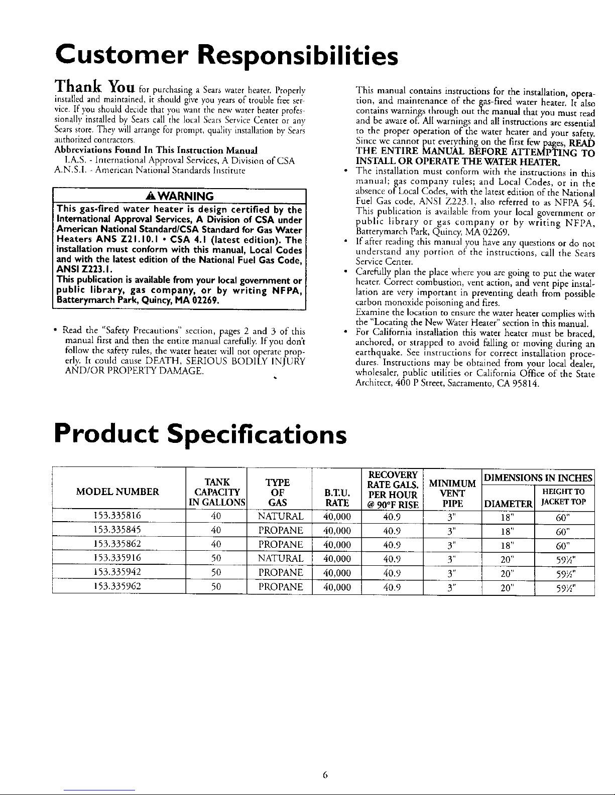
Product Specifications
MODEL NUMBER
153.335816
153.335845
153.335862
153.335916
153.335942
153.335962
TANK
CAPACITY
IN GALLONS
40
40
40
50
50
50
TYPE
OF
GAS
NATURAL
PROPANE
PROPANE
NATURAL
PROPANE
PROPANE
B.ZU.
RATE
40,000
40,000
40,000
40,000
40,000
40,000
RECOVERY
RATE GALS.
PER HOUR
@ 90°F RISE
40.9
40.9
40.9
40.9
40.9
40.9
MINIMUM
VENT
PIPE
3"
3"
3"
3"
3"
y'
DIMENSIONS IN INCHES
HEIGHTTO
DIAMETER JACKETTOP
18" 60"
18" 6O"
18" 6O"
20" 59½"
20" 59W'
20" 59_"
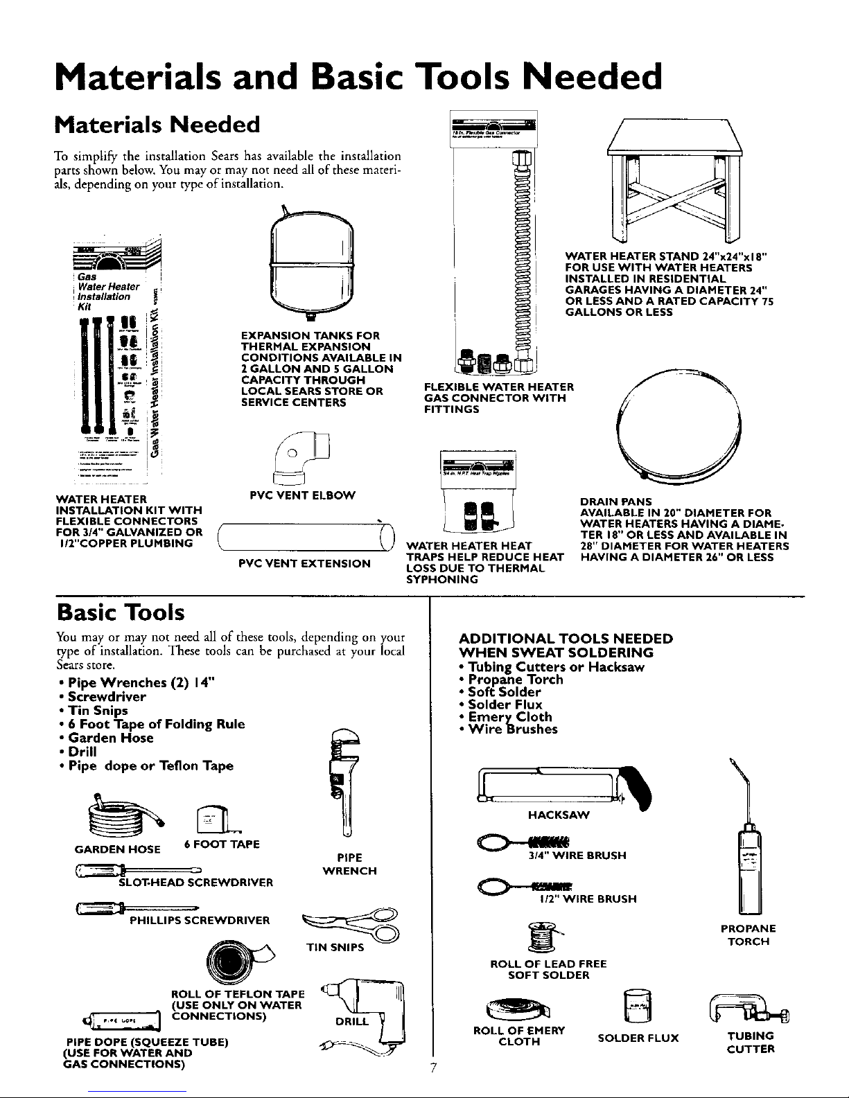
Materials and Basic Tools Needed
Materials Needed
To simplify the installation Sears has available the installation
parts shown below. You may or may not need all of these materi-
als, depending on your type of installation.
Gas
Water Heater
I Installation _
Kit
I
WATER HEATER
INSTALLATION KIT WITH
FLEXIBLE CONNECTORS
FOR 3/4" GALVANIZED OR
I/2"COPPER PLUMBING
EXPANSION TANKS FOR
THERMAL EXPANSION
CONDITIONS AVAILABLE IN
2 GALLON AND 5 GALLON
CAPACITY THROUGH
LOCAL SEARS STORE OR
SERVICE CENTERS
PVC VENT ELBOW
PVC VENT EXTENSION
FLEXIBLE WATER HEATER
GAS CONNECTOR WITH
FITTINGS
WATER HEATER HEAT
TRAPS HELP REDUCE HEAT
LOSS DUE TO THERMAL
SYPHONING
WATER HEATER STAND 24"x24"x18"
FOR USE WITH WATER HEATERS
INSTALLED IN RESiDENTiAL
GARAGES HAVING A DIAMETER 24"
OR LESS AND A RATED CAPACITY 75
GALLONS OR LESS
DRAIN PANS
AVAILABLE IN 20" DIAMETER FOR
WATER HEATERS HAVING A DIAME-
TER 18" OR LESS AND AVAILABLE IN
28" DIAMETER FOR WATER HEATERS
HAVING A DIAMETER 26" OR LESS
Basic Tools
You may or may not need all of these tools, depending on your
type of installation. These tools can be purchased at your local
Sears store,
• Pipe Wrenches (2) 14"
• Screwdriver
• Tin Snips
• 6 Foot Tape of Folding Rule
• Garden Hose
• Drill
• Pipe dope or Teflon Tape
GARDEN HOSE 6 FOOT TAPE
SLOT-HEAD SCREWDRIVER
PiPE
WRENCH
PHILLIPS SCREWDRIVER
ROLL OF TEFLON TAPE
(USE ONLY ON WATER
CONNECTIONS)
PIPE DOPE (SQUEEZE TUBE)
(USE FOR WATER AND
GAS CONNECTIONS)
TIN SNIPS
DRILL
ADDITIONAL TOOLS NEEDED
WHEN SWEAT SOLDERING
• Tubing Cutters or Hacksaw
• Propane Torch
• Soft Solder
• Solder Flux
_ EmeryCIoth
Wire Brushes
HACKSAW
314" WIRE BRUSH
112"WiRE BRUSH
ROLL OF LEAD FREE
SOFT SOLDER
PROPANE
TORCH
ROLL OF EMERY
CLOTH SOLDER FLUX TUBING
CUTTER
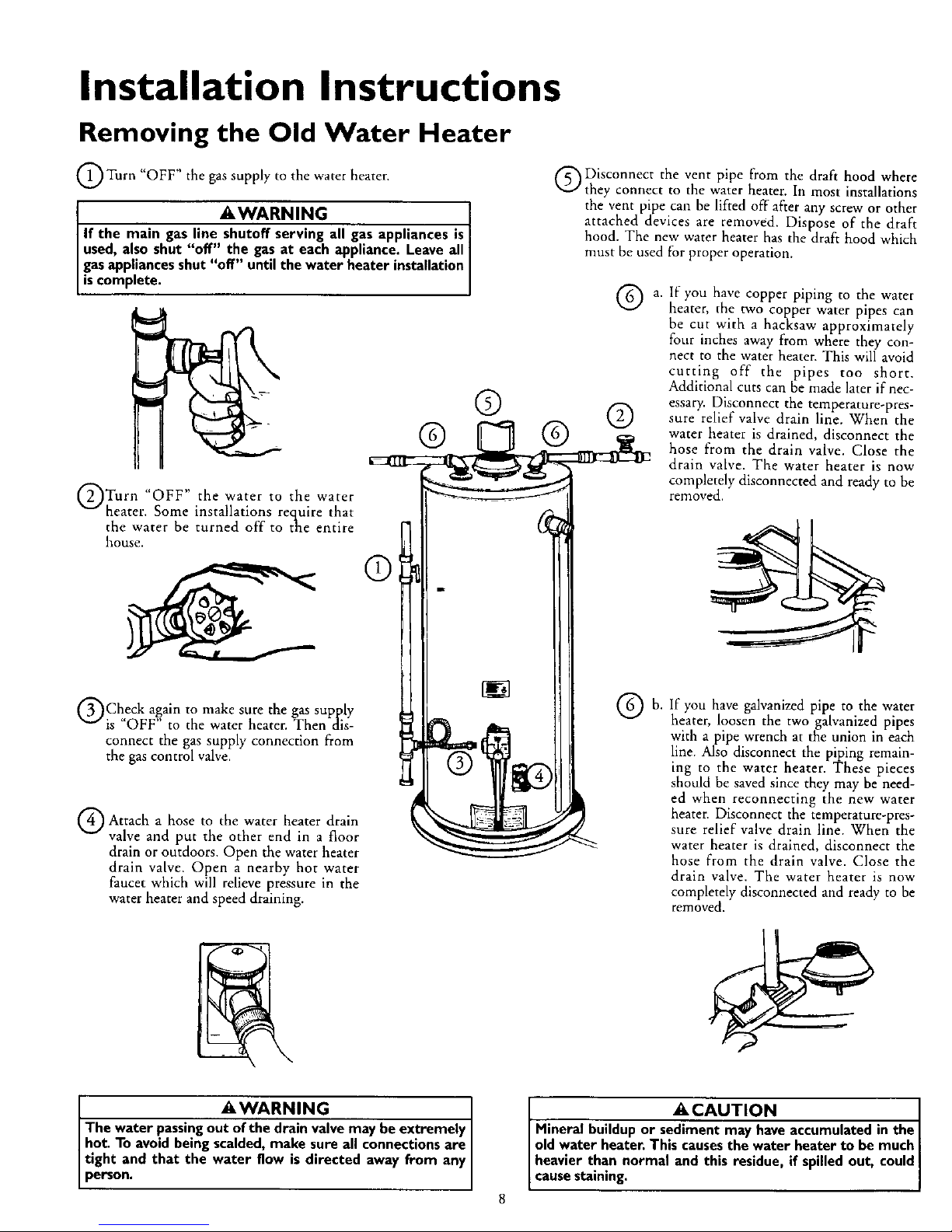
Installation Instructions
Removing the Old Water Heater
Turn "OFF" the gas supply to the water heater.
_,WARNING
If the main gas line shutoff serving all gasappliances is I
used,also shut "off" the gas at each appliance. Leave all
gasappliances shut "off" until the water heater installation
scomp ete.
Turn water to water
lIOF F" the
the
heater. Some installations require that
the water be turned off to the entire
house.
QCheck again to make sure the gas supply
is "OFF" to the water heater. Then dis-
connect the gas supply connection from
the gas control valve.
Q Attach hose the heater drain
a to water
valve and put the other end in a floor
drain or outdoors. Open the water heater
drain valve. Open a nearby hot water
faucet which will relieve pressure in the
water heater and speed draining.
Disconnect the vent pipe from the draft hood where
they connect to the water heater. In most installations
the vent pipe can be lifted off after any screw or other
attached devices are removed. Dispose of the draft
hood. The new water heater has the draft hood which
must be used for proper operation.
®
® ®
®
a,
®h"
If you have copper piping to the water
heater, the two copper water pipes can
be cut with a hacksaw approximately
four inches away from where they con-
nect to the water heater. This will avoid
cutting off the pipes too short.
Additional cuts can be made later if nec-
essary. Disconnect the temperature-pres-
sure relief valve drain line. When the
water heater is drained, disconnect the
hose from the drain valve. Close the
drain valve. The water heater is now
completely disconnected and ready to be
removed.
If you have galvanized pipe to the water
heater, loosen the two galvanized pipes
with a pipe wrench at the union in each
line. Also disconnect the piping remain-
ing to the water heater. These pieces
should be saved since they may be need-
ed when reconnecting the new water
heater. Disconnect the temperature-pres-
sure relief valve drain line. When the
water heater is drained, disconnect the
hose from the drain valve. Close the
drain valve. The water heater is now
completely disconnected and ready to be
removed.
WARNIN G
The water passing out of the drain valve may be extremely I
hot. To avoid being scalded, make sure all connections are I
tight and that the water flow is directed away from any
person.
A CAUTION ]
Mineral buildup or sediment may have accumulated in the I
old water heater. This causes the water heater to be much I
heavier than normal and this residue, if spilled out, could
cause staining.
Installation Instructions
Locating the New Water
Heater
You should carefully choose an indoor location for the new water
heater, because the placement is a very important consideration
for the safety of the occupants in the building and for the most
economical use of the appliance. This water heater is not for
use in mobile homes or outdoor installation.
Whether replacing an old water heater or putting the water
heater in a new location, the following critical points must be
observed.
1. The location selected sbould be indoors as close as practical
to the vent ternfination point, and as centralized with the
water piping system as possible. The water heater, as a[l water
heaters, will eventually leak. Do not install without adequate
drainage provisions where water flow will cause damage.
2. The vent piping cannot exceed a total of 35 feet inchlding
vertical and horizontal runs and have no more than 3 elbows.
it cannot slope downward and horizontal runs require/" per
foot rise. All horizontal runs require adequate support at 3½
feet intervals.
3. The water heater requires its own (separate) venting system.
It cannot be connected to an existing vent pipe or chimney.
It must terminate horizontally to the outdoors. Whenever
possible terminate the vent on the leaward side of the build-
ing. NOTE: Condensation may be created, at times, as the
combustion gases exit the vent cap and discoloration of
surfaces in proximity to the vent cap may occur.
_IWARNING
The power vent water heater requires itsown (separate) venting
system.It cannot be connectedto an existingvent pipe or chim-
ney.It must be terminated horizontallyto the outdoors.Failureto
properly installthe venting systemcan result inasphyxiation,a fire
or explosion and can causeDEATH, SERIOUS BODILY INJUR_,
OR PROPERTY DAMAGE.
4. The water beater comes equipped with a 5 foot power cord
which can be used to connect to a 110/120 volt power
source if(l) local codes allow, and (2) there is a three prong
receptacle available.
IIWARNING
Do not useanextensioncord.Ifthere isnot a suitablerecepta.I
tie and/orlocalcodesprohibituseof a powercord,field wiring
mustbe provded.
ACAUTION
WATER HEATERS EVENTUALLY LEAK: Installation of the
water heater must be accomplished in such a manner that if
the tank or any connections should leak, the flow of water
will not cause damage to the structure. When such locations
cannot be avoided, a suitable drain pan should be installed
under the water heater. Drain pans are available at your
local Sears store. Such a drain pan must be not greater than
1½ inchesdeep, have a minimum length and width of at least
2 inches greater than the water heater dimensions and must
be piped to an adequate drain. The pan must not restrict
combustion air flow. Under no circumstances is the manu-
facturer or Sears to be held liable for any water damage in
connection with this water heater.
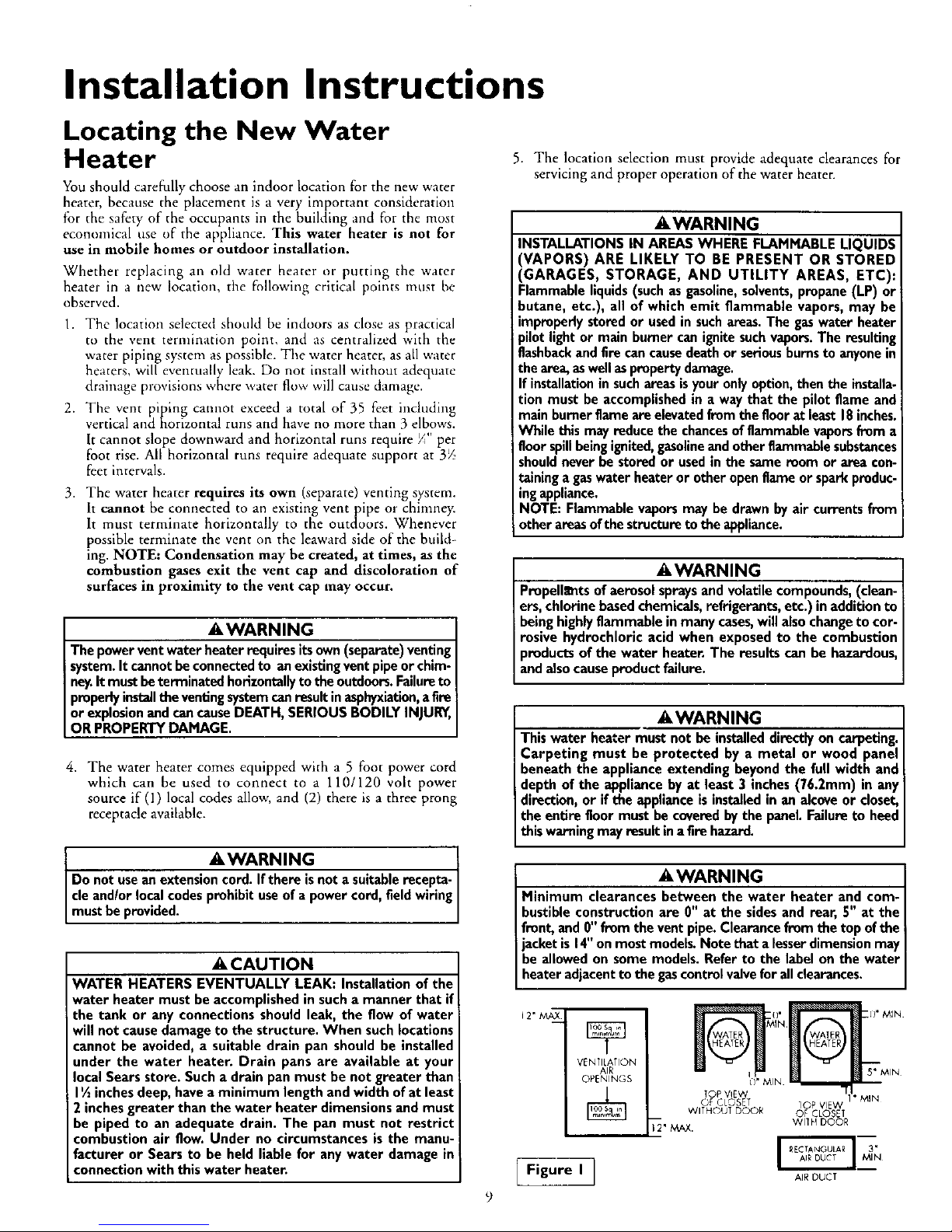
5. The location selection must provide adequate clearances for
servicing and proper operation of the water heater.
IIWARNING
INSTALLATIONS IN AREAS WHERE FLAMMABLE LIQUIDS
'VAPORS) ARE LIKELY TO BE PRESENT OR STORED
'GARAGES, STORAGE, AND UTILITY AREAS, ETC):
klammable liquids (such as gasoline,solvents, propane (LP) or
butane, etc.), all of which emit flammable vapors, may be
improperly stored or used in suchareas. The gas water heater
pilot light or main burner can ignite suchvapors.The resulting
flashbackand fire cancause death or serious bums to anyone m
the area,aswell as property damage.
If installation insuch areas isyour onlyoption, then the installa.
tion must be accomplished in a way that the pilot flame and
main burner flame are elevatedfrom the floor at least 18inches.
While this may reduce the chancesof flammable vapors from a
floor spillbeing ignited,gasolineand other flammable substances
shouldnever be stored or used in the same room or area con-
raininga gaswater heater or other open flame or spark produc-
ingappliance.
NOTE: Flammable vapors may be drawn by air currents from
other areasofthe structure to the appliance.
•_WARNING
Propell_nts of aerosol sprays and volatile compounds, (clean-
ers, chlorine based chemicals, refrigerants, etc.) inaddition to
being highly flammable in many cases,will also change to cor-
rosive hydrochloric acid when exposed to the combustion
products of the water heater. The results can be hazardous,
and also cause product failure.
AWARNING
This water heater must not be installeddirectly on carpeting.
Carpeting must be protected by a metal or wood panel
beneath the appliance extending beyond the full width and
depth of the appliance by at least 3 inches (76.2mm) in any
direction, or if the appliance is installed in an alcove or closet,
the entire floor must be covered by the panel. Failure to heed
this warning may result in a fire hazard.
AWARNING
Minimum clearances between the water heater and com-
bustible construction are 0" at the sides and rear, 5" at the
front, and fl" from the vent pipe. Clearance from the top of the
jacket is 14"on most models. Note that a lesserdimension may
be allowed on some models. Refer to the label on the water
heater adjacent to the gascontrol valvefor all clearances.
J2"_
VEN TILATION
AIR
OPENINGS
Figure I ]
_IIN I)" MIN
TOP VIEW II" MIN _
OF CLOSET 10P VIEW
WITHOUT DOOR OF CLOSET
_' MAX. Wl]H DOOR
AlE DUCT
Installation Instructions (cont'd)
IIWARNING
A gaswater heater cannotoperateproperlywithout the cor-
rect amount of air for combustion.Do not installin a con-
finedarea sucha closet,unlessyou provideair asshownin
the "Locating The New Water Heater" section. Never
obstructthe flowof ventilationair.If you haveany doubtsor
questionsat all,callyourgascompany.Failureto providethe
properamountof combustionair canresultin afire or explo-
sionand can causeDEATH, SERIOUS BODILY INJUR_,OR
PROPERTYDAMAGE.
from
any overhang
of Flue
li WARNING
If thiswater heaterwillbe usedinbeautyshops,barbershops,
cleaningestablishments,or self-servicelaundrieswith dry
cleaningequipment,it is imperativethat the water heater or
water heatersbe installedsothat combustionand ventilation
air be taken fromoutsidetheseareas.Referto the "Locating
The New Water Heater" sectionof this manualand alsothe
latest editionofthe NationalFuelGasCode,ANSI Z223.1,also
referred to as NFPA 54 for specificsprovidedconcerningair
required.
Combustion Air and Ventilation
When determining the installation location for apower vent
water heater, snow accumulation and drifting shouldbe consid-
ered in areas where applicable.
VENTING CLEARANCES
• 0" clearance for 3" PVC, ABSor CPVC Schedule40 vent piping
fromcombustiblesurfaces.
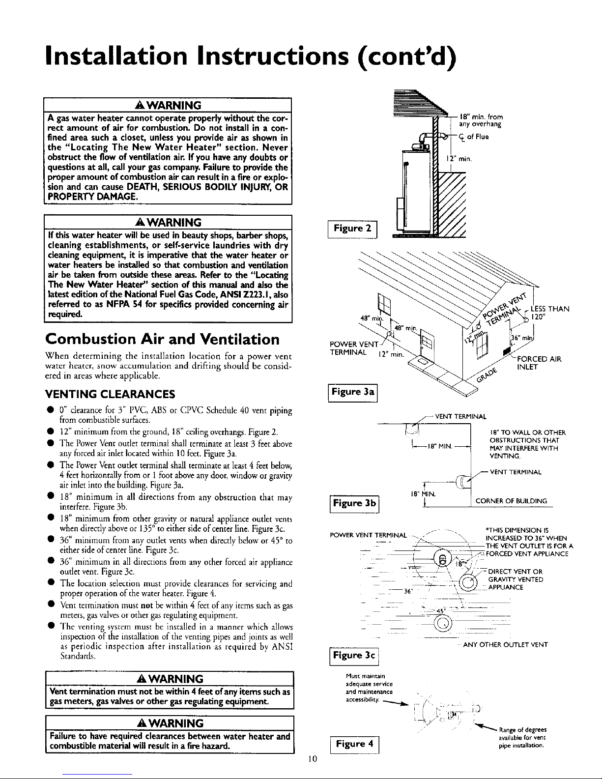
• 12"minimum from the ground, 18" ceilingoverhangs.Figure2.
• The PowerVentoutlet terminalshall terminateat least 3 feetabove
any forcedair inletlocatedwithin 10 feet.Figure3a.
• The PowerVentoutlet terminalshallterminate at least4 feetbelow,
4 feet horizontallyfrom or 1foot aboveany door, windowor gravity
airinlet into the building.Figure3a.
• 18" minimum in all directions from any obstruction that may
interfere.Figure3b.
• 18" minimum from other gravityor natural appliance outlet vents
when directlyaboveor 135° to either sideof centerline. Figure3c.
• 36" minimum from any outlet ventswhen directlybelowor 45° to
eithersideofcenter line. Figure3c.
• 36" minimum in all directionsfrom any other forcedair appliance
outletvent. Figure3c.
• The location selection must provide clearances for servicing and
properoperationof thewater heater.Figure4.
• Venttermination must not be within 4 feet ofany itemssuchas gas
meters,gasvalvesor othergasregulatingequipment.
• The venting system must be installed in a manner which allows
inspection of the installationof the venting pipesand jointsas well
as periodic inspection after installation as required by ANSI
Standards.
iI WARNING
Ventterminationmust not bewithin4 feetofanyitemssuchas
gasmeters,gasvalvesorother gasregulating equipment.
iIWARNING
Failureto haverequired clearancesbetweenwater heaterand
combust bemater al w resut na firehazard.
10
Figure 2 ]
TERMINAL 12" min.
INLET
Figure 3a]
S VENT TERMINAL
L_ I E" MIN,
[F,gu.3b]
IB" TO WALL OR OTHER
OBSTRUCTIONS THAT
MAY INTERFEREWITH
VENTING.
rF VENT TERMINAL
CORNER OF BUILDING
*THIS DIMENSION IS
POWER VENT TERHINAL _ J_ _\
_ _ INCREASED TO 36" WHEN
__ _-- - _ _" _THE VENT OUTLET ISFOR A
_ _ _j_ FORCED VENT APPLIANCE
_B"*/'
_ _ GRAVITY VENTED
- "- _ ' _ _-DIRECTVENTOR
36,_ _--'- \ _ APPLIANCE
45°
ANY OTHER OUTLET VENT
[Figure3cI
Must maintain
adequate service
and maintenance
ibility.
Range of degrees
[ Figure 4 ] available for vent
pipe installation.
Installation Instructions (cont'd)
Combustion Air and Ventilation
for Appliances Located in
Unconfined Spaces
Unconfined Space is a space whose volume is not less than 50 cubic
feet per 1,000 Btu per hour of the aggregate input rating of all appli-
ances installed in that space. Rooms communicating directly with the
space in which the appliances are installed, through openings not fur_
nished with doors, are considered a part of the unconfined space.
In unconfined spaces in buildings, infiltration may be adequate to
provide air for combustion, ventilation and dilution of flue gases.
However, in buildings of tight construction (for example, weather
stripping, heavily insulated, caulked, vapor barrier, etc.), additional air
may need to be ])rovided using the methods described in Combustion
Airand Ventilation for Appliances Located in Confined Spaces.
Combustion Air and Ventilation
for Appliances Located in
Confined Spaces
Confined Space is a space whose volume is less than 50 cubic feet per
1,000 Btu per hour of the aggregate input rating of all appliances
installed in that space.
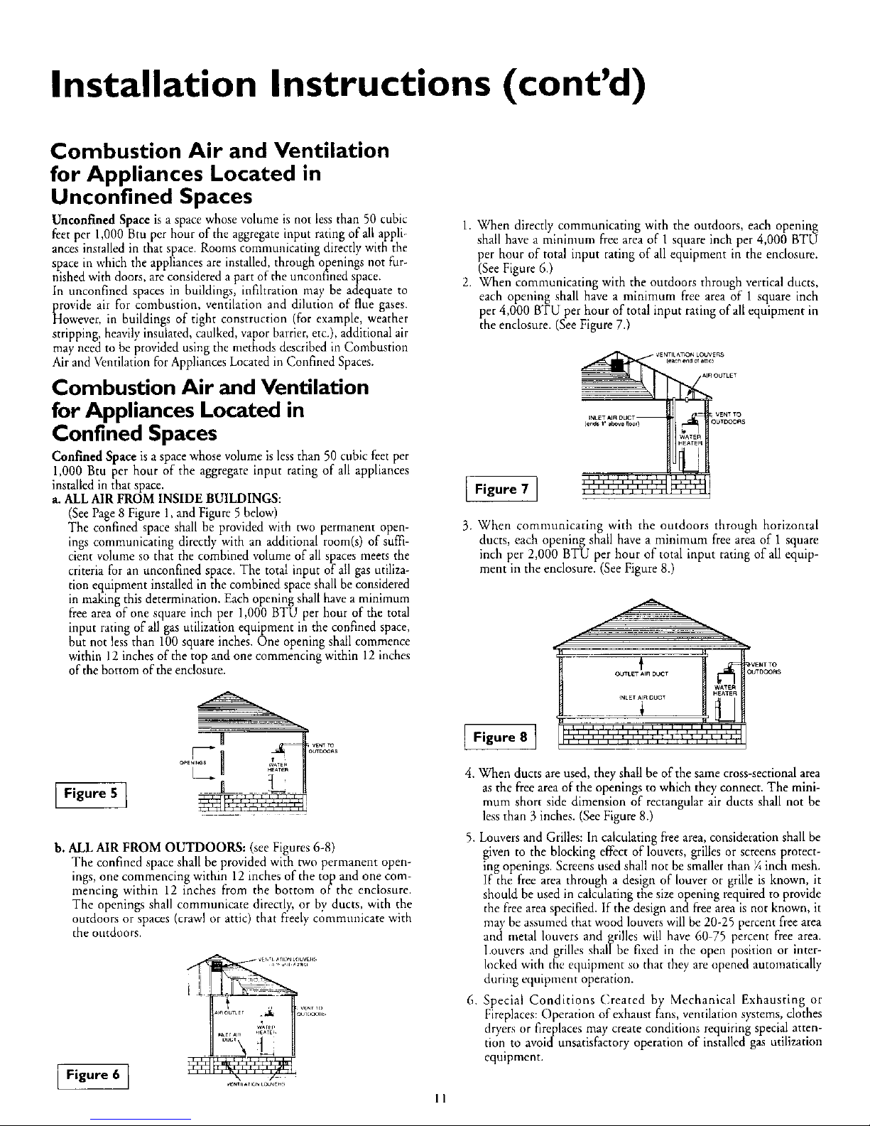
a. ALL AIR FROM INSIDE BUILDINGS:
(See Page 8 Figure 1, and Figure 5 below)
The confined space shall be provided with two permanent open-
ings communicating directly with an additional room(s) of suffi-
cient volume so that the combined volume of all spaces meets the
criteria for an unconfined space. The total input of all gas utiliza-
tion equipment installed in the combined space shall be considered
in making this determination. Each opening shall have a minimum
free area of one square inch per 1,000 BTU per hour of the total
input rating of all gas utilization equipment in the confined space,
but not less than 100 squareinches. One opening shall commence
within 12 inches of the top and one commencing within 12 inches
of the bottom of the enclosure.
Figure 5 I
_L
b. ALL AIR FROM OUTDOORS: (see Figures 6-8)
The confined space shall be provided with two permanent open-
ings, one commencing within 12 inches of the top and one com-
mencing within 12 inches from the bottom of the enclosure.
The openings shall communicate directly, or by ducts, with the
outdoors or spaces (crawl or attic) that freely communicate with
the outdoors.
j Figure 6 ]
, ii
\ /
_Utlt_rlO_LOUVE.S
1. When directly communicating with the outdoors, each opening
shallhave a minintum free area of 1 square inch per 4,000 BTU
per hour of total input rating of all equipment in the enclosure.
(See Figure6.)
2. When communicating with the outdoors through verticalducts,
each opening shall have a minimum free area of 1 square inch
per 4,000 BTU per hour of total input rating of allequipment in
the enclosure. (SeeFigure 7.)
Figure 7 ]
_NTILAT_N LOUVERS
{_ch cad o_a_m)
AIR OUTLEt
_VEN_ TO
_TDOO_sINLETAIn DUCT
',',',',',',',%'! i_ll:J
.......... t,,
3. When communicating with the outdoors through horizontal
ducts, each opening shall have a minimum free area of 1 square
inch per 2,000 BTU per hour of total input rating of all equip-
ment in the enclosure. (SeeFigure 8.)
Figure 8 ]
OUTLET _1_ DUCT
WATER
HE_TE_
iiirlll,,,,,llll
,_,,,,_,,,rll_llll
_VENTTO
OUTDOORS
4. When ducts are used, they shallbe of the same cross-sectionalarea
as the freearea of the openings to which they connect. The mini-
mum short side dimension of rectangular air ducts shall not be
lessthan 3 inches. (SeeFigure 8.)
5. Louvers and Grilles:In calculating freearea, consideration shall be
given to the blocking effect of louvers, grillesor screens protect-
ing openings. Screens used shall not be smaller than¼ inch mesh.
If the free area through a design of louver or grille is known, it
should be used in calculating the sizeopening required to provide
the free area specified. If the design and freearea is not known, it
may be assumed that wood louvers willbe 20-25 percentfree area
and metal louvers and grilles wi!l have 60-75 percent free area.
Louvers and grilles shallbe fixed in the open _osition or inter-
locked with the equipment so that they are opened automatically
during equipment operation.
6. Special Conditions Created by Mechanical Exhausting or
Fireplaces:Operation of exhaust fans, ventilation systems,clothes
dryers or fireplacesmay create conditions requiring specialatten-
tion to avoid unsatisfactory operation of installed gas utilization
equipment.
11
Installation Instructions (cont'd)
Water Piping
AWARNING
HOTTER WATER CAN SCALD: Water heaters are intended to
Jmduce hot water. Water heated to a temperature which will
satisfyclothes washing, dishwashing,and other sanitizing needs
can scald and permanently injure you upon contact. Some pee-
fie are more likelyto be permanently injured by hot water than
others. These includethe elderly,children,the infirm, or physical-
ly/mentally handicapped. If anyone usinghot water inyour home
fits into one of thesegroupsor ifthere isa localcodeor state law
requiring a certain temperature water at the hotwater tap,then
_u must take specialprecautions.In additionto usingthe lowest
mssible temperature setting that satisfiesyour hot water needs,
ameans suchas a mixing valve, shouldbe used at the hot water
taps used by these people or at the water heater. Mixing valves
are availableat plumbing supplyor hardware stores.Follow man.
ufacturers instructions for installation of the valves. Before
changing the factory setting on the thermostat, read the
"Temperature Regulation" sectionin thismanual.
This water heater shall not be connected to any heating systems
or component(s) used with a non-potable water heating appli-
ance.
If a water heater is installed in a closed water supply system;
such as one having a back-flow preventer, check valve, water
meter with a check valve, etc.., in the cold water supply; means
shall be provided to control thermal expansion. Contact the
local utility or local Sears Service Center on how to control this
situation.
NOTE: To protect against untimely corrosion of hot and
cold water fittings, it is strongly recommended that dielec-
tric unions or couplings be installed on this water heater
when connected to copper pipe.
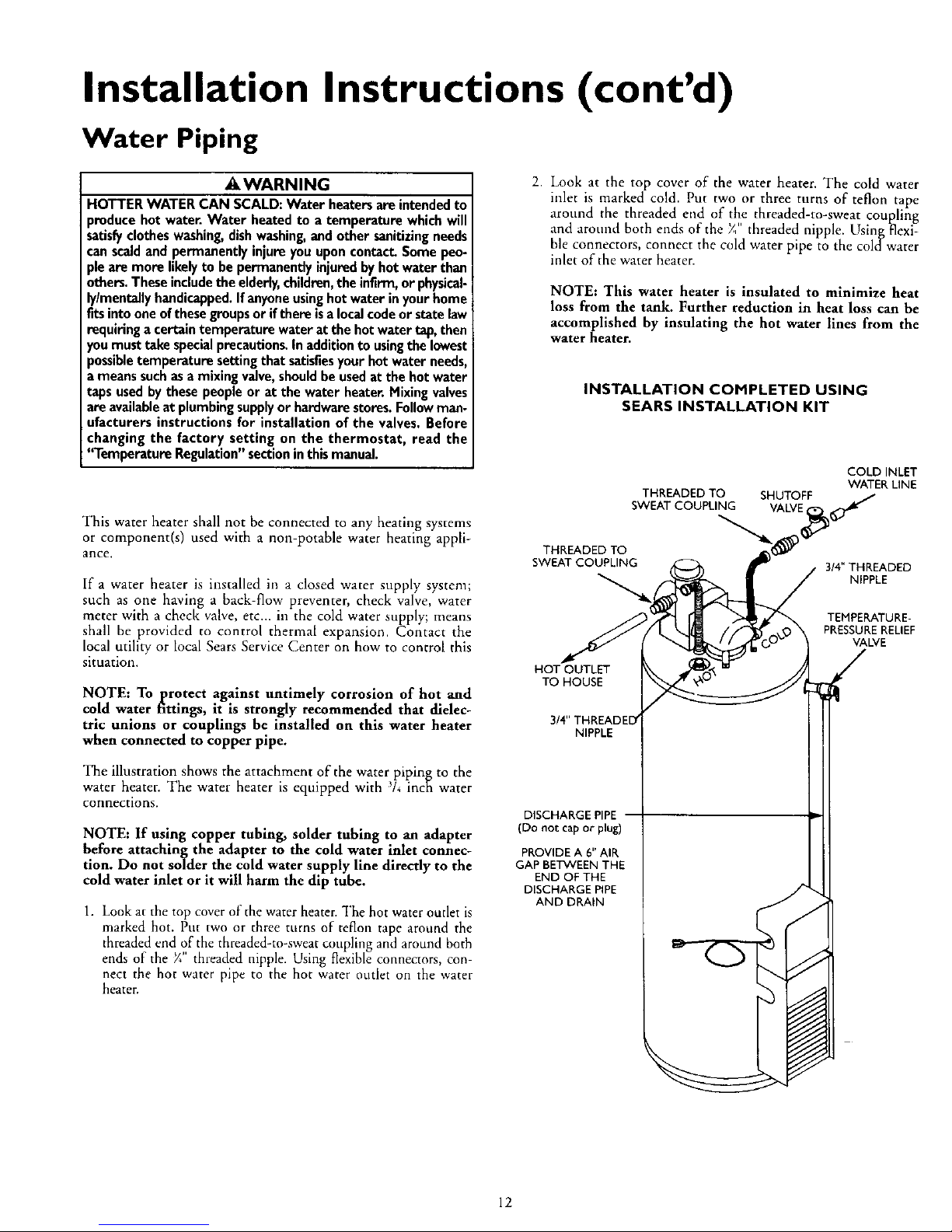
The illustration shows the attachment of the water piping to the
water heater. The water heater is equipped with / inch water
connections.
NOTE: If using copper tubing, solder tubing to an adapter
before attaching the adapter to the cold water inlet connec-
tion. Do not solder the cold water supply line directly to the
cold water inlet or it will harm the dip tube.
1. Look at the top cover of the water heater. "I'he hot water outlet is
marked hot. Put two or three turns of teflon tape around the
threaded end of the threaded-to-sweat coupling and around both
ends of the X" th eaded npple. Us'ng flex'ble connectors, con
nect the hot water pipe to the hot water outlet on the water
heater.
2. Look at the top cover of the water heater. The cold water
inlet is marked cold. Put two or three turns of teflon tape
around the threaded end of the threaded-to-sweat coupling
and around both ends oiCthe X" threaded nipple. Using flexi-
ble connectors, connect the cold water pipe to the coldwater
inlet of the water heater.
NOTE: This water heater is insulated to minimize heat
loss from the tank. Further reduction in heat loss can be
accomplished by insulating the hot water lines from the
water heater.
INSTALLATION COMPLETED USING
SEARS INSTALLATION KIT
THREADED TO SHUTOFF
SWEAT COUPLING VALVE
THREADED TO
SWEAT COUPLING
HOT OUTLET
TO HOUSE
NIPPLE
DISCHARGE PIPE
(Do not cap or plug)
PROVIDE A 6" AIR
GAP BETVVEEN THE
END OF THE
DISCHARGE PIPE
AND DRAIN
COLD INLET
WATERLINE
3!4" THREADED
NIPPLE
TEMPERATURE-
PRESSURERELIEF
VALVE
12
 Loading...