

Kenmore 153.33443 User Manual
Owner’s Manual
Kenmore
HydroSense
Gas Water Heater
FOR POTABLE WATER HEATING ONLY.
NOT SUITABLE FOR SPACE HEATING.
NOT FOR USE IN MOBILE HOMES.
MODEL NO.
153.334430
153.334630
40 Gallon
50 Gallon
Ak
• Safety Instructions
• Installation
• Operation
• Care and Maintenance
• Troubleshooting
• Parts List
03 Technology® Gas Water Heaters meet
the new ANSI Z21.10.1 standard that deals
with the accidental or unintended ignition
of flammable vapors, such as those
emitted by gasoline.
AWARNING
Read and understand instruction
manual and safety messages
before installing, operating or
servicing this water heater.
Failure to follow instructions and
safety messages could result In
death or serious injury.
Instruction manual must remain
with water heater.
For Your Safety
AN ODORANT IS ADDED TO THE GAS USED BY THIS WATER HEATER.
WARNING: if the information in these
instructions is not followed exactly, a fire
or explosion may result causing property
damage, personal injury or death.
- Do not store or use gasoline or other
flammable vapors and liquids in the
vicinity of this or any other appliance.
-WHATTODOIFYOUSMELLGAS:
• Do not try to light any appliance.
• Do not touch any electrical switch; do
not use any phone in yourbuilding.
• Immediately call your gas supplier
from a neighbor’s phone. Follow the
gas supplier’s instructions.
ADVERTENCIA
Si no puede leer o entender el inglés y necesita el manual instructivo
y/o etiquetas en español puede obtenerlos llamando al
1-800-821-2017. NO TRATE DE INSTALAR O OPERAR ESTE
CALENTADOR DEAGUAsi no entiende la información en las etiquetas
o en el manual instructivo. No hacer caso de esta advertencia podría
resultar en la MUERTE O GRAVES LESIONES CORPORALES.
Sears, Roebuck and Co., Hoffman Estates, IL 60179 U.S.A
PRINTED IN U.S.A. 0806
www.sears.com
• If you cannot reach your gas supplier,
call the fire department.
- Installation and service must be
performed by a qualified installer,
service agency or the gas supplier.
PART NO. 185614-000

SAFE INSTALLATION, USE AND SERVICE
Your safety and the safety of others is extremely important in the installation, use and servicing of this water heater.
Many safety-related messages and instructions have been provided in this manual and on your own water heater to warn you and
others of a potential injury hazard. Read and obey all safety messages and instructions throughout this manual. It is very important
that the meaning of each safety message is understood by you and others who install, use or service this water heater.
This is the safety alert symbol. It is used to alert you to
potential personal injury hazards. Obey all safety
messages that follow this symbol to avoid possible
injury or death.
DANGER indicates an imminently
A DANGER
A WARNING
A CAUTION
hazardous situation which, if not avoided,
could result in death or injury.
WARNING indicates a potentially hazardous
situation which, if not avoided, could result
in death or injury.
CAUTION indicates a potentially hazardous
situation which, if not avoided, may result
in minor or moderate injury.
CAUTION used without the safety alert
CAUTION
Ail safety messages will generally tell you about the type of hazard, what can happen if you do not follow the safety message and
how to avoid the risk of injury.
Gas Supplier: The natural gas or propane utility or service who supplies gas for utilization by the gas burning
symbol indicates a potentially hazardous
situation which, if not avoided, could resuit
in property damage.
IMPORTANT DEFINITIONS
appliances within this application. The gas supplier typically has responsibility for the inspection and code approval of
gas piping up to and including the natural gas meter or propane storage tank of a building. Many gas suppliers also
offer service and inspection of appliances within the building.
© Sears, Roebuck and Co.
^WARNING
Read and understand instruction
manual and safety messages
before installing, operating or
servicing this water heater.
Failure to follow instructions and
safety messages could result in
death or serious injury.
Instruction manual must remain
with water heater.
AWARNlNG
Fire Hazard
For continued protection against
risk of fire:
•Do not install water heater on
carpeted floor.
•Do not operate water heater if
flood damaged.
▲DANGER
Water temperature over 125°F
(52°C) can cause severe burns
instantly resulting in severe injury
or death.
Children, the elderly, and the
physically or mentally disabled
are at highest riskfor scald injury.
Feel water before bathing or
showering.
Temperature limiting valves are
available.
Read instruction manual for safe
temperature setting.
A WARNING
Fire or Explosion Hazard
• Do not store or use gasoline or other flammable
vapors and liquids in the vicinity of this or any other
appliance.
• Avoid all ignition sources if you smell LP gas.
• Do not expose water heater control to excessive gas
pressure.
• Use only gas shown on rating plate.
• Maintain required clearances to combustibles.
• Keep ignition sources away from faucets after
V extended period of non-use.
Read instruction manual before
installing, using or servicing
é
water heater.
W I
Awarning
Explosion Hazard
■ Overheated water can cause
water tank explosion.
^ Properly sized temperature
and pressure relief valve must
be installed in opening
provided.
Awarning
Breathing Hazard - Carbon Monoxide Gas
■ Install vent system in accordance with
codes.
■ Do not operate water heater it flood
damaged.
■ High altitude orifice must be installed for
operation above 7,700 feet (2,347 m).
■ Do not operate if soot buildup.
■ Do not obstruct water heater air intake
with insulating jacket
■ Do not place chemical vapor emitting
products near water heater.
■ Gas and carbon monoxide detectors
are available.
Breathing carbon monoxide can cause brain damage or
death. Always read and understand instruction manual
CAUTION
Improper installation and use may result
in property damage.
• Do not operate water heater if flood damaged.
• Inspect and replace anode.
• Install in location with drainage,
• Fill tank with water before operation.
• Be alert for thermal expansion
Refer to instruction manual for installation and service.

TABLE OF CONTENTS
SAFE INSTALLATION, USE AND SERVICE ..............................................................................................................................................................................2
SAFETY PRECAUTIONS .............................................................................................................................................................................................................3
TABLE OF CONTENTS ................................................................................................................................................................................................................4
CUSTOMER RESPONSIBILITIES
PRODUCT SPECIFICATIONS......................................................................................................................................................................................................5
MATERIALS AND BASIC TOOLS NEEDED................................................................................................................................................................................6
Material Needed.....................................................................................................................................................................................................................6
Basic Tools............................................................................................................................................................................................................................ 6
TYPICAL INSTALLATION ............................................................................................................................................................................................................7
INSTALLATION INSTRUCTIONS
Removing the Old Water Heater...........................................................................................................................................................................................8
Facts to Consider About the Location..............................................................................................................................................................................9-10
Insulation Jackets................................................................................................................................................................................................................10
Combustion Air and Ventilation Appliances
in Unconfined Spaces
Combustion Air and Ventilation Appliances
in Confined Spaces........................................................................................................................................................................................................ 11-12
Wafer Piping....................................................................................................................................................................................................................12-13
Temperature Pressure Relief Valve............................................................................................................................................................................... 13-14
Filling the Water Heater.......................................................................................................................................................................................................14
Venting
...
..................................................................................................................................................................................................... 14-15
Gas Piping...................................................................................................................................................................................................................... 15-16
Sediment Trap................................................................................................................................................................................................................16-17
OPERATING INSTRUCTIONS .............................................................................................................................................................................................18-19
Lighting & Operating Label..................................................................................................................................................................................................18
Temperature Regulation
SERVICE AND ADJUSTMENT..............................................................................................................................................................................................20-22
Tank (Sediment) Cleaning...................................................................................................................................................................................................20
Venting System Inspection.................................................................................................................................................................................................. 20
Burner Inspection.................................................................................................................................................................................................................20
Burner Cleaning ..................................................................................................................................................................................................................20
Housekeeping ............................................................................................................................................................................................. 20-21
Anode Rod Inspection.........................................................................................................................................................................................................21
Temperature-Pressure Relief Valve Operation...................................................................................................................................................................21
Draining...........................................................................................................................................................................................................................21-22
Drain Valve Washer Replacement......................................................................................................................................................................................22
Service
................................................................................................................................................................................................................ 22
Start Up Conditions.........................................................................................................................................................................................................23-24
Thermal Expansion......................................................................................................................................................................................................23
Strange Sounds...........................................................................................................................................................................................................23
Draft Hood Operation.............................................................................................................................................................................................23-24
Condensation...............................................................................................................................................................................................................24
Smoke/Odor................................................................................................................................................................................................... 24
Operational Conditions...................................................................................................................................................................................................24-25
Smelly Odor..................................................................................................................................................................................................................24
Air in Hot Water Faucets..............................................................................................................................................................................................25
High Temperature Shut-Off System............................................................................................................................................................................24
Leakage Checkpoints
SERVICE INSTRUCTIONS FOR GAS CONTROL VALVE ASSEMBLY..............................................................................................................................26-27
TROUBLESHOOTING GUIDE...............................................................................................................................................................................................28-29
PARTS ORDER LIST..................................................................................................................................................................................................................30
NOTES........................................................................................................................................................................................................................................31
WARRANTY.................................................................................................................................................................................................................................32
................................................................................................................................................................................. 5
..........
.................................................................................................................................................................. 8-16
......................................................................................................................................................................................... 10
........................................................................................................................................................................................ 19
.................................................................................................................................................................................... 25

CUSTOMER RESPONSIBILITIES
Thank You for purchasing a Kenmore water heater. Properly
installed and maintained, it should give you years of trouble free
service. If you should decide that you want the new water heater
professionally installed by Sears call 1-800-4-MY-HOIVIE®. They
will arrange for prompt, quality installation by Sears authorized
contractors.
Abbreviations Found In This Instruction Manual:
CSA - Canadian Standards Association
ANSI - American National Standards Institute
NFPA - National Fire Protection Association
ASME - American Society of Mechanical Engineers
GAMA - Gas Appliance Manufacturers Association
This gas-fired water heater is design certified by CSA
INTERNATIONAL under American National Standard/CSA
Standard for Gas Water Heaters ANSI Z21.10.1 • CSA 4.1
(current edition).
Read the “Safety Precautions” section, page 3 of this manual
first and then the entire manual carefully. If you don't follow
the safety rules, the water heater will not operate properly. It
could cause DEATH, SERIOUS BODILY INJURY AND/OR
PROPERTY DAMAGE.
This manual contains instructions for the installation, operation,
and maintenance of the gas-fired water heater. It also contains
warnings through out the manual that you must read and be
aware of. All warnings and all instructions are essential to the
proper operation of the water heater and your safety. Since
we cannot put everything on the first few pages, READ THE
ENTIRE MANUAL BEFORE ATTEMPTING TO INSTALL OR
OPERATE THE WATER HEATER.
The installation must conform with these instructions and the
local code authority having jurisdiction. In the absence of
local codes, installations shall comply with the following:
The National Fuel Gas Code ANSI Z223.1/NFPA 54. This
publication is available from the Canadian Standards
Association, 8501 East Pleasant Valley Rd, Cleveland Ohio
44131, or The National Fire Protection Association,
1 Batterymarch Park, Quincy, MA 02269.
If after reading this manual you have any questions or do not
understand any portion of the instructions, call the Sears
Service Center.
Carefully plan the place where you are going to put the water
heater. Correct combustion, vent action, and vent pipe
installation are very important in preventing death from
possible carbon monoxide poisoning and fires. See
figure 1.
Examine the location to ensure the water heater complies
with the Facts to Consider About the Location section in this
manual.
For California installation this water heater must be braced,
anchored, or strapped to avoid falling or moving during an
earthquake. See instructions for correct installation
procedures. Instructions may be obtained from your local
dealer, wholesaler, public utilities or California Office of the
State Architect, 400 P Street, Sacramento, CA 95814.
Massachusetts Oode requires this water heater to be installed
in accordance with Massachusetts 248-CMR 2.00: State
Plumbing Code and 248-CMR 5.00.
Complies with SCAQMD rule #1121 and districts having
equivalent NOx requirements.
PRODUCT SPECIFICATIONS
RECOVERY
TANK
CAPACITY
MODEL NUMBER
153.334430 40(151) NATURAL 40,000 46.9 3” (76) or 4" (102) 20 1/2” (521) 55 1/2" (1,410)
153.334530 50(189) NATURAL 40,000 45.8 3" (76) or 4" (102) 22” (558) 56 1/2" (1,435)
IN GALS (LTRS)
TYPE
OF
GAS
INPUT
RATE
(Btu/hrj
RATE GALS.
PER HOUR
@90°F RISE
MINIMUM
VENT PIPE
INCHES
(mm)
DIAMETER
INCHES
(mm)
DIMENSIONS
IN INCHES (mm)
HEIGHT TO
JACKET TOP
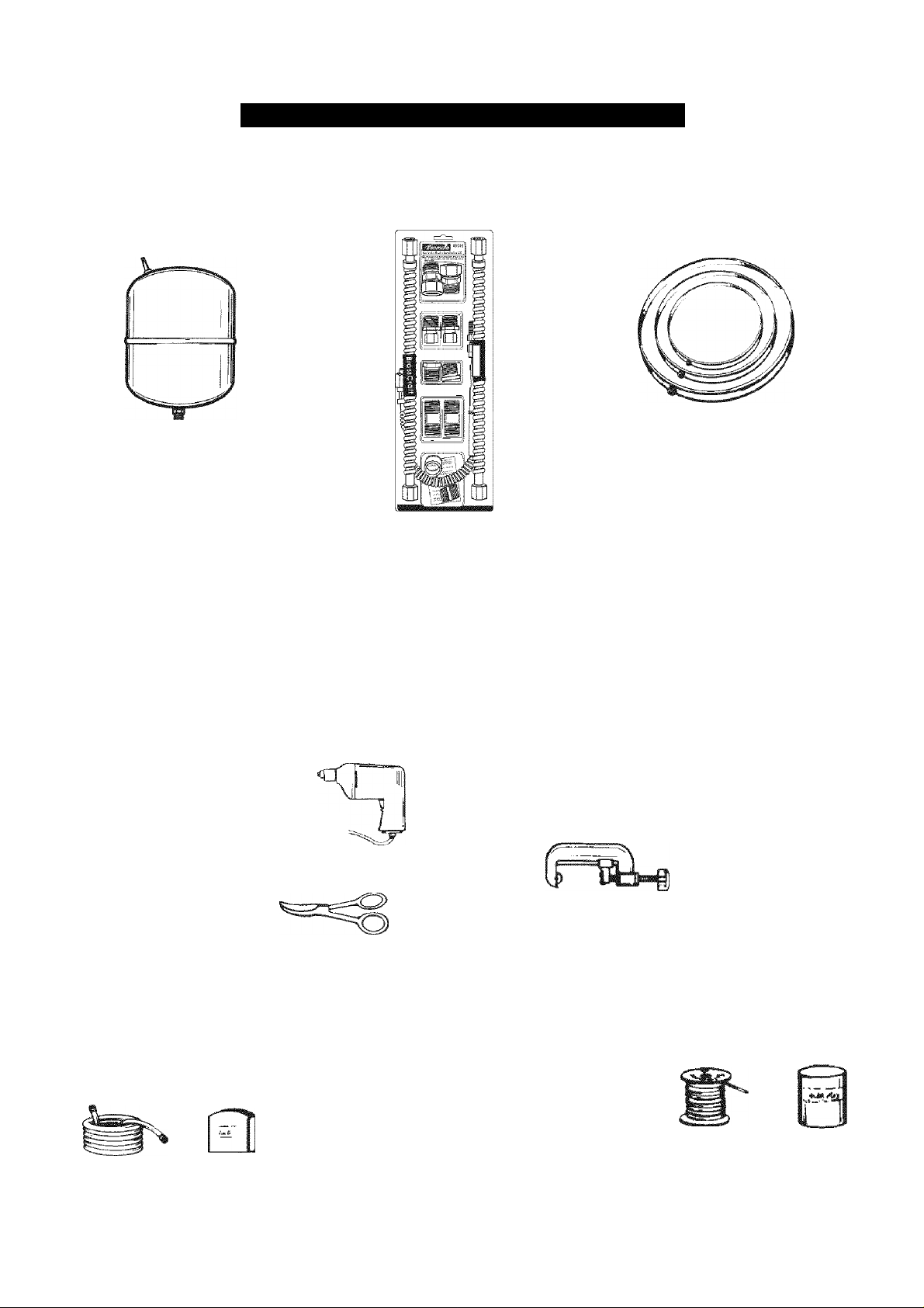
MATERIALS AND BASIC TOOl-S NEEDED
Materials Needed
To simplify the installation Sears has available the installation parts shown below. You may or may not need all of these materials,
depending on your type of installation.
EXPANSION TANKS FOR
THERMAL EXPANSION
CONDITIONS AVAILABLE
m 2 GALLONS
(7.6 LITERS) AND
5 GALLONS {18,9 LITERS)
CAPACITY HROUGH
LOCAL SEARS STORE
OR SERVICE CENTER.
WATER HEATER INSTALLATION KIT WITH
FLEXIBLE CONNECTORS FOR 3/4”
(19.05 mm) OR 1/2” (12.7 mm) THREADED OR
COPPER PLUMBING AND FLEXIBLE WATER
HEATER GAS CONNECTOR WITH FITTINGS.
Basic Tools
You may or may not need all these tools, depending on your
type of installation. These tools can be purchased at your local
Sears Store.
Pipe Wrenches (2) 14” (356 mm)
Screwdriver
Tin Snips
8’ (1.82 m) Tape or Folding Ruler
Garden Hose
Drill
Pipe Dope or Teflon Tape
SLOT-HEAD SCREWDRIVER
DRILL
DRAIN PANS AVAILABLE IN
20” (508 mm) DIAMETER FOR
WATER HEATERS HAVING A
DIAMETER 18” (457 mm) OR
LESS, 24” {610mm) DIAMETER
FOR WATER HEATERS HAVING
A DIAMETER 22” {559 mm) OR
LESS AND AVAILABLE IN 28”
(711 mm) DIAMETER FOR
WATER HEATERS HAVING A
DIAMETER 26” (660 mm) OR
LESS.
Additional Tools Needed When Sweat Soldering
• Tubing Cutters or Hacksaw
• Propane Tank
• Soft Solder
• Solder Flux
• Emery Cloth
• Wire Brushes
TUBING CUTTER
PHILLIPS SCREWDRIVER
ROLL OF TEFLON
TAPE (USE ONLY ON
WATER CONNECTIONS)
GARDEN HOSE
€ FOOT TAPE
TIN SNIPS
P.fii
C
PIPE DOPE
{SQUEEZE TUBE)
USE FOR WATER AND GAS
CONNECTIONS
PIPE WRENCH
03CI
HACKSAW
3/4" (19 mm) WIRE BRUSH
1/2” (13 mm) WIRE BRUSH
EMERY CLOTH
ROLL OF LEAD-FREE
SOFT SOLDER
ROLL OF
SOLDER
FLUX
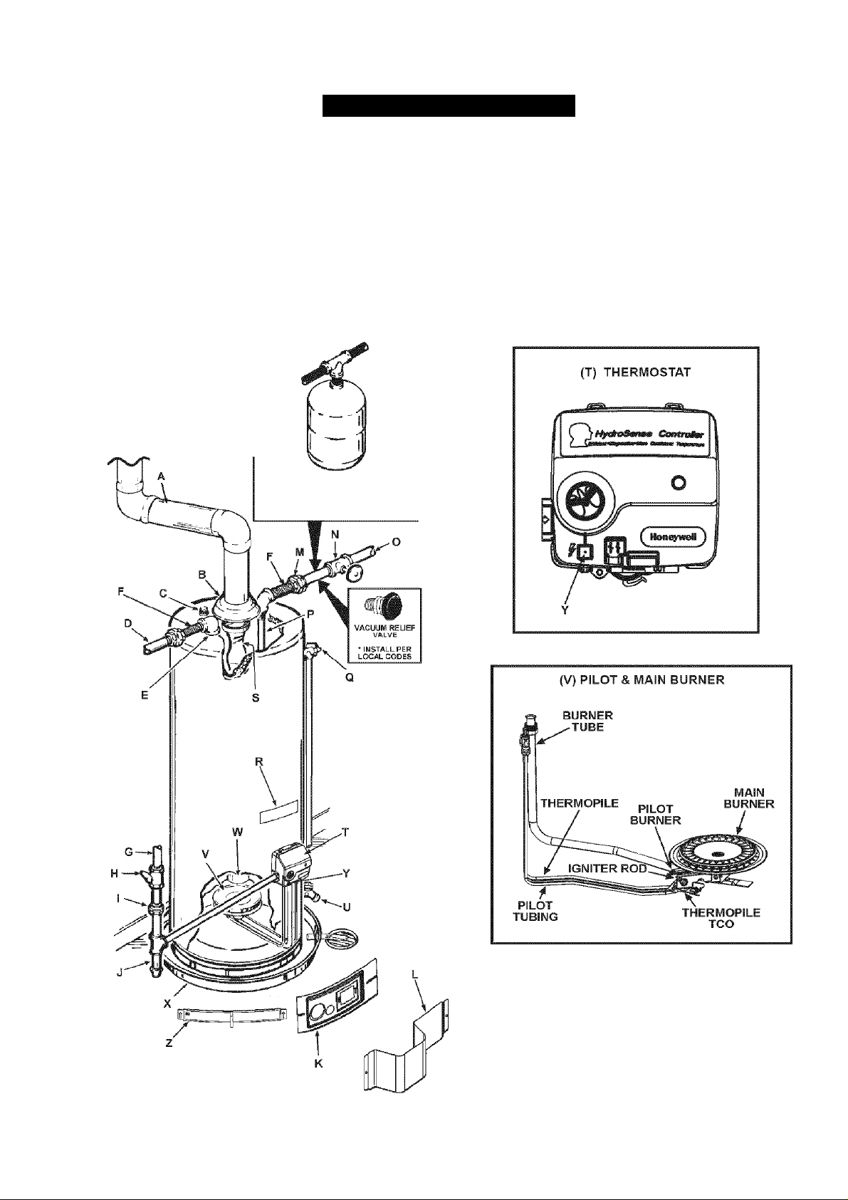
TYPICAL INSTALLATION
GET TO KNOW YOUR WATER HEATER - GAS MODELS
A Vent Pipe J Drip Leg (Sediment Trap) S Flue Baffle
B Draft Hood K Inner Door T Thermostat
c Anode L Outer door u Drain Valve
D Hot Water Outlet M Union V Pilot and Main Burner
E Outlet N Inlet Water Shut-off Valve w Flue
F Flexible Water Connections O Cold Water Inlet X Drain Pan
G Gas Supply P Inlet Dip Tube Y Piezo Igniter
H Manual Gas Shut-off Valve
I Ground Joint Union R Rating Piate
* INSTALL IN ACCORDANCE
WITH LOCAL CODES.
*DRIP LEG AS REQUIRED
BY LOCAL CODES.
TO VENT TERMINATION
ON ROOF
INSTALL THERMAL EXPANSION
TANK OR DEVICE IF WATER
HEATER IS INSTALLED IN A
CLOSED WATER SYSTEM
Temperature-Pressure Relief Valve z Air intake Screen
Q
“ALL PIPING MATERIALS TO BE
SUPPLIED BY CUSTOMERS.
FIGURE 1.
7
INSTALLATION INSTRUCTIONS
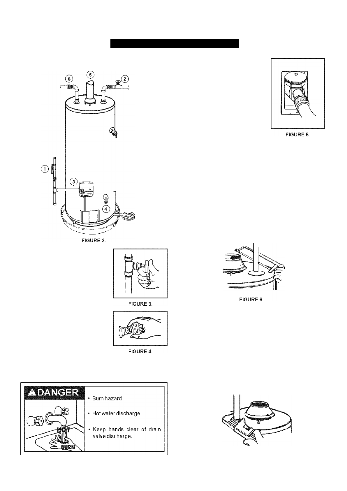
Removing the Old Water Heater
Attach a hose to the water heater
drain valve and put the other end
in a floor drain or outdoors. Open
the water heater drain valve. Open
a nearby hot water faucet which will
relieve pressure in the water heater
and speed draining. The water
passing out of the drain valve may
be extremely hot. To avoid being
scalded, make sure all connections
are tight and that the water flow is
directed away from any person, see
Figures 2 and 5.
© Disconnect the vent pipe from the draft hood where it connects
to the water heater. In most installations the vent pipe can
be lifted off after any screw or other attached devices are
removed. Dispose of the draft hood. The new water heater
has a draft hood which must be used for proper operation.
If you have copper piping to the water heater, the two copper
water pipes can be cut with a hacksaw approximately four
inches away from where they connect to the water heater,
see Figure 6. This will avoid cutting off pipes too short.
Additional cuts can be made later if necessary. Disconnect
the temperature-pressure relief valve drain line. When the
water heater is drained, disconnect the hose from the drain
valve. Close the drain valve. The water heater is now
completely disconnected and ready to be removed.
© Turn “OFF” the gas supply to the
water heater.
If the main gas line shut-off valve
serving all gas appliances is used,
also shut “OFF” the gas at each
appliance. Leave all gas
appliances shut “OFF” until the
water heater installation is
completed, see Figures 2 and 3.
© Turn “OFF” the water supply to the
water heater at the water shut-off
valve or water meter. Some
installations require that the water
be turned off to the entire house,
see Figures 2 and 4.
Check again to make sure the gas supply is “OFF” to the
water heater. Then disconnect the gas supply connection from
the gas control valve.
If you have galvanized pipes to the water heater, loosen the
two galvanized pipes with a pipe wrench at the union in each
line. Also disconnect the piping remaining to the water heater,
see Figure 7. These pieces should be saved since they may
be needed when reconnecting the new water heater.
Disconnect the temperature-pressure relief valve drain line.
When the water heater is drained, disconnect the hose from
the drain valve. Close the drain valve. The water heater is
now completely disconnected and ready to be removed.
Mineral buildup or sediment may have accumulated in the
old water heater. This causes the water heater to be much
heavier than normal and this residue, if spilled out, could cause
staining.
FIGURE 7.
Facts to Consider About
the Location
Devices that will turn off the gas supply to a gas water heater
while at the same time shutting off its water supply.
Carefully choose an indoor location for the new water heater,
because the placement is a very important consideration for the
safety of the occupants in the building and for the most
economical use of the appliance. This water heater is not for
use in manufactured (mobile) homes or outdoor installation.
Whether replacing an old water heater or putting the water heater
in a new location, the following critical points must be observed:
• Select a location indoors as close as practical to the gas vent
or chimney to which the water heater vent is going to be
connected, and as centralized with the water piping system
as possible.
” Selected location must provide adequate clearances for
servicing and proper operation of the water heater.
CAUTION
Property Damage Hazard
All water heaters eventually leak
Do notinstall without adequate drainage.
Installation of the water heater must be accomplished in such a
manner that if the tank or any connections should leak, the flow
will not cause damage to the structure. For this reason, it is not
advisable to install the water heater in an attic or upper floor.
When such locations cannot be avoided, a suitable drain pan
should be installed under the water heater. Drain pans are
available at your local Sears or hardware store. Such a drain
pan must have a minimum length and width of at least 2 inches
(51 mm) greater that the water heater dimensions and must be
piped to an adequate drain. The pan must not restrict combustion
air flow.
Awarning
Fire or Explosion Hazard
• Do not store or use gasoline or other flammable
vapors and liquids in the vicinity of this or any other
appliance.
• Avoid all ignition sources if you smell LP gas.
• Do not expose water heater control to excessive gas
pressure.
• Use only gas shown on rating plate.
■ Maintain required clearances to combustibles.
• Keep ignition sources away from faucets after
V extended period of non-use.
Read instruction manual before
installing, using or servicing
é
INSTALLATIONS IN AREAS WHERE FLAMMABLE LIQUIDS
(VAPORS) ARE LIKELY TO BE PRESENT OR STORED
(GARAGES, STORAGE AND UTILITY AREAS. ETC.):
Flammable liquids (such as gasoiine, solvents, propane [LP or
butane, etc.] and other substances such as adhesives, etc.) emit
flammable vapors which can be ignited by a gas water heater's
pilot light or main burner. The resulting flashback and fire can
cause death or serious burns to anyone in the area. Even though
this water heater is a flammable vapors ignition resistant water
heater and is designed to reduce the chances of flammable
vapors being ignited, gasoline and other flammable substances
should never be stored or used in the same vicinity or area
containing a gas water heater or other open fiame or spark
producing appliance.
Also, the water heater must be located and/or protected so it is
not subject to physical damage by a moving vehicle.
water heater.
Water heater life depends upon water quality, water pressure
and the environment in which the water heater is installed. Water
heaters are sometimes installed in locations where leakage may
result in property damage, even with the use of a drain pan piped
to a drain. However, unanticipated damage can be reduced or
prevented by a leak detector or water shut-off device used in
conjunction with a piped drain pan. These devices are available
from some plumbing supply wholesalers and retailers, and detect
and react to leakage in various ways:
• Sensors mounted in the drain pan that trigger an alarm or
turn off the incoming water to the water heater when leakage
is detected.
‘ Sensors mounted in the drain pan that turn off the water supply
to the entire home when water is detected in the drain pan.
‘ Water supply shut-off devices that activate based on the water
pressure differential between the cold water and hot water
pipes connected to the water heater.
Awarning
Fire Hazard
For continued protection against
risk of fire:
•Do not install water heater on
carpeted floor.
•Do not operate water heater if
flood damaged.
This water heater must not be installed directly on carpeting.
Carpeting must be protected by metal or wood panel beneath
the appliance extending beyond the full width and depth of the
appliance by at least 3 inches (76.2mm) in any direction, or if the
appliance is installed in an alcove or closet, the entire floor must
be covered by the panel. Failure to heed this warning may result
in a fire hazard.
A WARNING
Fire or Explosion Hazard
Read instruction manual before installing,
using or servicing water heater.
Improper use may result in fire or
explosion.
Maintain required clearances to
è
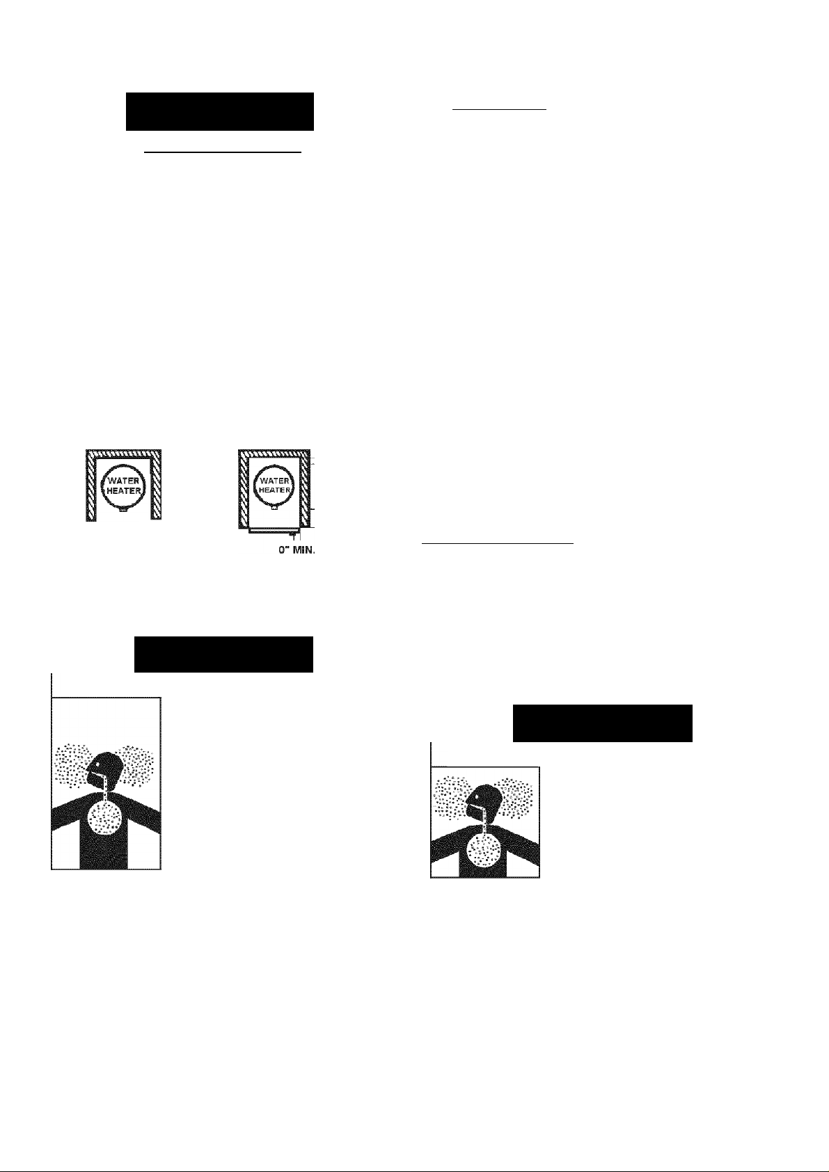
Minimum clearances between the water heater and combustible
construction are 0 inch at the sides and rear,
4 inches (102 mm) at the front, and 6 inches (153 mm) from the
vent pipe, see Figure 8. Clearance from the top of the jacket is 12
inches (305 mm) on most models. Note that a lesser dimension
may be allowed on some models, refer to the label attached
adjacent to the gas control valve on the water heater.
combustibles.
TOP VIEW
OF CLOSET
WITHOUT DOOR
I I 0" MIN.
: 0" MIN.
TOP VIEW
OF CLOSET
WITH DOOR
0" MIN.
4" MIN.
(104 mmj
j. 12 " MAX. [30 cm)
T I ™STi'l
VENTILATION
AIR
OPENING^
t
i
12" MAX.
FRONT VIEW T
OF DOOR
If this water heater will be used in beauty shops, barber shops,
cleaning establishments, or self-service laundries with dry
cleaning equipment, it is imperative that the water heater or water
heaters be installed so that combustion and ventilation air be
taken directly from outdoors (direct vent).
Propellants of aerosol sprays and volatile compounds, (cleaners,
chlorine based chemicals, refrigerants, etc.) in addition to being
highiy flammable in many cases, will also change to corrosive
hydrochloric acid when exposed to the combustion products of
the water heater. The results can be hazardous, and also cause
product failure.
insulation Blankets
(30 cm)
FIGURE 9.
_____________________
№CTANQULAR
AIR DUCT
AIR DUCT
3" MIN.
(7®,2 mm)
FIGURE 8.
AWARNING
Breathing Hazard - Carbon Monoxide Gas
Install water heater in accordance
with the instruction manual and
NFPA 54.
To avoid injury, combustion and
ventilation air must be taken from
outdoors.
Do not place chemical vapor
emitting products near water
heater.
Breathing carbon monoxide can cause brain damage or
death. Always read and understand Instruction manual.
A gas water heater cannot operate properly without the correct
amount of air for combustion, see Figure 9. Do not install in a
confined area such as a closet, unless you provide air as shown
in the Locating The New Water Heater section. Never obstruct
the flow of ventilation air. If you have any doubts or questions at
all, call your gas supplier. Failure to provide the proper amount
of combustion air can result in a fire or explosion and cause
death, serious bodily injury, or property damage.
Insulation blankets available to the general public for external
use on gas water heaters are not necessary with Kenmore
products. The purpose of an insulation blanket is to reduce the
standby heat loss encountered with storage tank heaters. Your
Kenmore water heater meets or exceeds the National Appliance
Energy Conservation Act standards with respect to insulation
and standby loss requirements, making an insulation blanket
unnecessary.
Awarning
Breathing Hazard - Carbon Monoxide Gas
Do not obstruct water heater air
intake with insulating blanket.
Gas and carbon monoxide detectors
are available
Install water heater in accordance
with the instruction manual.
Breathing carbon monoxide can cause brain damage or
death. Always read and understand instruction manual.
Jim WARNING
Should you choose to apply an insulation blanket to this heater,
you should follow these instructions (See Figure 1 for
identification of components mentioned below). Failure to follow
these instructions can restrict the air flow required for proper
combustion, potentially resulting in fire, asphyxiation, serious
personal injury or death.
10
 Loading...