

K^ nm o r^
Owners
Manual
FOR POTABLE WATER
HEATING ONLY
NOT SUITABLE FOR
SPACE HEATING
NOT FOR USE IN.
MOBILE HOMES
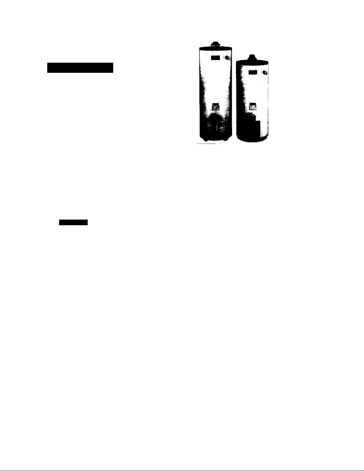
Model No.
153.334290 40 Gal. Short
153.334390 30 Gal.
153.334490 40 Gal.
153.334590 so Gal,
Caution:
Read and Follow
All Safety Rules and
Operating Instructions
Before First Use of
This Product.
"ENERGY EFFICIENTES
GAS WATER HEATER
• Safety Instructions • Care and Maintenance
• Installation • Troubleshooting
• Operation • Parts List
For Your Safety
AN ODORANT IS ADDED TO THE GAS USED BY THIS
WATER HEATER
WARNING; If the information in these instructions are not fol
lowed exactly, a fire or explosion may result, causing property
damage, personal injury or death.
-Do not store or use easoline or other flammable vapors and liq
uids in the vicinity of mis or any other appliance.
-WHAT TO DO IF YOU SMELL GAS
• Do not try to light any appliance.
• Do not touch any electrical switch; do not use any phone in your
building.
• Immediately call your gas supplier from a neighbor’s phone.
Follow the gas supplier’s instructions.
• If you can not reach your gas supplier, call the fire department.
-Installation and service must be performed by a qualified installer,
service agency or the gas supplier.
Save this Manual for Future Reference.
Sears, Roebuck and Co., Hoffman Estates, IL 60179 U.S.A.
A WARNING
Improper installation, adjustment, alteration, service or maintenance
can cause DEATH, SERIOUS BODILY INJURY, OR PROPERTY DAM
AGE. Refer to this manual for assistance or consult the local Sears
Service Center or gas utility for further information.
A WARNING
Flammable vapors may be drawn by air currents from other areas
of the structure to this appliance.
AWARNING
READ THE GENERAL SAFETY SECTION BEGINNING ON INSIDE
COVER AND THEN THIS ENTIRE MANUAL BEFORE INSTALLING
OR OPERATING THIS WATER HEATER.

Safety Precautions
AWARNING
Improper installation, adjustment, alteration, service
or maintenance can cause DEATH, SERIOUS BODILY
INJURY OR PROPERTY DAMAGE. Refer to this manu
al for assistance or consuit your local Sears Service
Center for further information.
AWARNING
WATER HEATERS EQUiPPED FOR ONE TYPE GAS
ONLY: This water heater is equipped for one type gas
oniy. Check the modei rating plate near the gas control
valve for the correct gas. DO NOT USE THIS WATER
HEATER WITH ANY GAS OTHER THAN THE ONE
SHOWN ON THE MODEL RATING PLATE. Failure to
use the correct gas can cause problems which can resuit in
DEATH, SERIOUS BODILY INJURY, OR PROPERTY
DAMAGE. If you have any questions or doubts consult
your gas supplier or locai utility.
AWARNING
INSTALLATIONS IN AREAS WHERE FLAMMABLE LIQ
UIDS (VAPORS) ARE LIKELY TO BE PRESENT OR
STORED (GARAGES, STORAGE, AND UTILITY AREAS,
ETC): Flammable liquids (such as gasoline, solvents,
propane (LP) or butane, etc.), all of which emit flammabie
vapors, may be improperiy stored or used in such areas.
The gas vrater heater pilot light or main burner can ignite
such vapors. The resulting flashback and fire can cause
death or serious bums to anyone in the area, as weil as
property damage.
if installation in such areas is your only option, then the
installation must be accomplished in a way that the pilot
flame and main burner flame are elevated from the floor
at least 18 inches. While this may reduce the chances of
flammable vapors from a floor spill being ignited, gasoiine
and other flammabie subst»ices should never be stored or
used in the same room or area containing a gas water
heater or other open flame or spark producing appiiance.
NOTE: Flammable vapors may be drawn by air currents
from other areas of the structure to the appliance.
AWARNING
If this water heater will be used in beauty shops, barber
shops, cieaning estabiishments, or self-service laundries
with dry cleaning equipment, it is imperative that the
water heater or water heaters be installed so that com
bustion and ventiiation air be taken from outside these
areas. Refer to the “Facts to Consider About the
Location” section of this manual and also the latest edi
tion of the National Fuel Gas Code, ANSI Z223.I, also
referred to as NFPA 54 for specifics provided concerning
air required.
AWARNING
A fire can start if combustible materials such as clothing,
cieaning materials, or flammable liquids are placed against
or next to the water heater.
_______________
^
AWARNING
At the time of manufrcture this water heater was provid
ed with a combination temperature-pressures relief valve
certified by alinationaliy recognized testing iaboratory
that maintains periodic inspection of production of iisted
equipment or materiais, as meeting the requirements for
Relief Valves and Automatic Gas Shutoff Devices for Hot
Water Suppiy Systems, and the latest edition of ANSI
Z2i.22 and the code requirements of ASME. If replaced,
the valve must meet the requirements of local codes, but
not less than a combination temperature and pressure
relief valve certified as meeting the requirements for
Relief Valves and Automatic Gas Shutoff Devices for Hot
Water Supply Systems, ANSI Z2I.22 by a nationally rec
ognized testing laboratory that maintains periodic
inspection of production of listed equipment or
materials.
The valve must be marked with a maximum set pressure
not to exceed the marked hydrostatic working pressure
of the water heater (ISO lbs./sq. in.) and a discharge
capacity not less than the water heater input rate as
shown on the model rating plate. (Electric heaters watts divided by 1000 x 3415 equal BTU/Hr. rate.)
Your local jurisdictional authority, while mandating the
use of a temperature-pressure relief valve complying
with ANSI Z21.22 and ASME, may require a valve model
different from the one furnished with the water heater.
Compliance with such local requirements must be satis
fied by the installer or end user of the water heater with
a locally prescribed temperature-pressure relief valve
installed in the designated opening in the water heater in
place of the factory furnished valve.
For safe operation of the water heater, the relief valve
must not be removed from it’s designated opening or
plugged.
The temperature-pressure relief valve must be installed
directly into the fitting of the water heater designated for
the relief valve. Position the valve downward and provide
tubing so that any discharge will exit only within 6 inches
above, or at any distance below the structural floor. Be
certain that no contact is made with any live electrical
part. The discharge opening must not be blocked or
reduced in size under any circumstances. Excessive
length, over 30 feet, or use of more than four elbows can
cause restriction and reduce the discharge capacity of
the valve.
No valve or other obstruction is to be placed between
the relief valve and the tank. Do not connect tubing
directly to discharge drain unless a 6" air gap is provided.
To prevent bodily injury, hazard to life, or property dam
age, the relief valve must be allowed to discharge water
in quantities should circumstances demand. If the dis
charge pipe is not connected to a drain or other suitable
means, the water flow may cause property damage.
The Discharge Pipe:
* Must not bie smaller in size than the outlet pipe size of
the valve, or have any reducing couplings or other
restrictions.
* Must not be plugged or blocked.
* Must be of material listed for hot water distribution.
* Must be installed so as to allow complete drainage of
both the temperature-pressure relief valve, and the dis
charge pipe.
* Must terminate at an adequate drain.
* Must not have any valve between the relief valve and
tank.
Safety Precautions
AWARNING
A gas water heater cannot operate properly without the
correct amount of air for combustion. Do not install in a
confined area such a closet, unless you provide air as
shown in the “Facts to Consider About the Location” sec
tion. Never obstruct the flow of ventilation air. If you have
any doubts or questions at all, call your gas company.
Failure to provide the proper amount of combustion air
can result in a fire or explosion and can cause DEATH,
SERIOUS BODILY INJURY, OR PROPERTY DAMAGE.
AWARNING
HOTTER WATER CAN SCALD; Water heaters are
intended to produce hot water. Water heated to a tem
perature which will satisfy clothes washing, dish washing,
and other sanitizing needs can scald and permsmently
injure you upon contact. Some people are more litely to
be permanently Injured by hot water than others. Tliese
include the elderly, children, the infirm, or physically/mentafly handicapped. If anyone using hot water in your home
fits into one of these graups or If there is a local code or
state law requiring a certain temperature water at the hot
water tap, then you must tala special precautions. In addi
tion to using the lowest possible temperature setting that
satisfies your hot water needs, a means such as a mixing
valve, should be used at the hot water taps used by these
people or at the water heater. Mixing valves are available
at plumbing supply or hardware stores. Follow manufac
turers instructions for installation of the valves. Before
changing the factory setting on the thermostat, read the
"Temperature Regulation" section in this manual.
AWARNING
Soot build-up indicates a problem titat requires correc
tion before further use. Turn “OFF” gas to water heater
and leave “OFF" until repairs are made, because failure
to correct the cause of the sooting can result in a fire or
explosion causing DEATH, SERIOUS BODILY INJURY,
OR PROPERTY DAMAGE.
AWARNING
This water heater must not be installed directly on car
peting. Carpeting must be protected by a metal or wood
panel beneath the appliance extending beyond the full
width and depth of the appliance by at least 3 inches
p6.2mm) in any direction, or if the appliance is installed
in an alcove or closet, the entire floor must be covered by
the panel. F^lure to heed this warning may result in a
fire hazard.
AWARNING
VENT DAMPERS - Any vent damper, whether it is operat
ed thermally or otherwise must be removed if its use
inhibits proper drafting of the water heater.
Thermally Operated Vent Dampers; Gas-fired water
heaters having thermal efficiency in excess of 80% may
produce a relatively low flue gas temperature. Such tem
peratures may not be high enough to properly open ther
mally operated vent dampers. This would cause spillage of
flue gases and may cause carbon monoxide poisoning.
Vent dampers must bear evidence of certification as com
plying with the latest edition of American National
Standard ANSI Z2I.68 (ANSI Z2I.66 & 67. respectively,
cover electrically and mechanically actuated vent
dampers). Before instaJIation of any vent damper, consult
your loc^ Sears Service Center or the gas utility for fur
ther information.
AWARNING
• The appliance and its individual shutoff valve must be dis
connected from tile gas supply piping system during any
pressure testing of the gas system at test pressures in
excess of 'A pound per square inch (3.5kPa).
> The appliance must be isolated from the gas supply pip
ing system by closing its individual manud shutoff valve
during any pressure testing of the gas supply piping sys
tem at test pressures equal or less than 'A pound per
square inch (3.5kPa).
AWARNING
BEFORE LIGHTING [PROPANE (L.P.) GAS WATER
HEATERS]; Propane (L.P.) gas is heavier than air. Should
there be a leak in the system, the gas will settle near the
ground. Basements, crawl spaces, skirted areas under
mobile homes (even when ventilated), closets and areas
below ground level will serve as pockets for the accumula
tion of this gas. Before attempting to light or relight the
water heater^ pilot or turning on a nea^ electri^ light
switch, be absolutely sure there is no accumulated gas in
the area. Search for odor of gas by sniffing at ground level
in the vicinity of the appliance. If odor is detected, follow
steps indicated at “For Your Safety” on the cover page of
this manual then leave the premises.
AWARNING
Chemical vapor corrosion of the flue and vent system
may occur if air for combustion contains certain chemical
vapors. Spray can propellants, cleaning solvents, refrigera
tor and air conditioner refrigerants, swimming pool
chemicals, calcium and sodium chloride, waxes, bleach,
and process chemicals are typical compounds which are
potentially corrosive.
_______________AWARNING
Obstructed or deteriorated vent systems may present a
serious hedth risk or asphyxiation.
Safety Precautions continued on page 4
________________

Safety
AWARNING
The mter heater with draft hood installed must be prop
erly vented to a chimney which terminates outdoors.
Never operate the water heater unless it is vented to the
outdoors and has adequate air supply to avoid risks of
improper operation, explosion or asphyxiation.
AWARNING
Minimum clearances between the water heater and com
bustible or non-combustible construction are I" at the
sides and rear, 4" at the front, and 6" from the vent pipe.
Clearance from the top of the jacket is 18" on most mod
els. Note that a lesser dimension may be allowed on some
models. Refer to the label on the water heater adjacent to
the gas control valve for all clearances.________
AWARNING
Do not use this appliance if any part of it has been under
water. Immediately call a Sears Service Technician to
inspect the appliance and to replace the gas control or any
part of the burner system which has been under water.
AWARNING
HYDROGEN GAS: Hydrogen gas can be produced in a hot
water system that has not been used for a long period of
time (generally two weeks or more). Hydrogen gas Is
ex^mely flammable and explosive. To prevent the possi
bility of injury under these conditions, we recommend the
hot water faucet be opened for several minutes at the
kitchen sink before any electrical appliances which are
connected to the hot water system are used (such as a dis
hwasher or vnishing machine). If hydrogen gas is present,
there will probably be an unusual sound similar to air
escaping through the pipe as the hot water faucet is
opened. There must be no smoking or open flame near
the foucet at the time it is open.
ACAUTION
WATER HEATERS EVENTUALLY LEAK: Installation of
the mter heater must be accomplished in such a manner
that if the tank or any connections should leak, the flow of
vrater will not cause damage to the structure. When such
locations cannot be avoided, a suitable drain pan should
be installed under the water heater. Drain pans are avail
able at your local Sears store. Such a drain pan must be
not greater than I 'A inches deep, have a minimum length
and width of at least 1 inches greater than the water
heater dimensions and must be piped to an adequate
drain. The pan must not restrict combustion air flow.
Under no circumstances is the manufacturer or Sears to
be held liable for any water damage in connection with
this water heater.
AWARNING
INSULATING JACKETS: When installing an external
water heater insulation jacket on a gas water heater:
• DO NOT cover the temperature-pressure relief valve.
• DO NOT put insulation over any part of the top of the
gas water heater.
• DO NOT put insulation over the gas control valve or gas
control valve/bumer cover, or any access areas to the
burner.
• DO NOT let insulation around the gas water heater to
get within 8 inches of the floor (air must get to the
burner).
• DO NOT cover or remove operating instructions, and
safety related warning labels and materials affixed to the
water heater.
Failure to heed this will result in the possibility of a fire or
explosion.

Table of Contents
Safety Precautions........................................................................................................................................................................................2-4
Table of Contents..............................................................................................................................................................................................5
Customer Responsibilities................................................................................................................................................................................6
Product Specifications......................................................................................................................................................................................6
Materials and Basic Tools Needed...................................................................................................................................................................7
Materials Needed.......................................................................................................................................................................................7
Basic Tools................................................................................................................................................................................................7
Installation Instructions................................................................................................................................................................................sa6
Removing the Old Water Heater...............................................................................................................................................................8
Facts to Consider About the Location.......................................................................................................................................................9
Combustion Air and Ventilation for Appliances in Ünconhncd Spaces.................................................................................................10
Combustion Air and Ventilation for Appliances in Confined Spaces.................................................................................................. 10
Water Piping............................................................................................................................................................................................11
Temperature-Pressure Relief Valve........................................................................................................................................................ 12
Filling the Water Heater......................................................................................................................................................................... 13
Venting................................................................................................................................................................................................13-14
Gas Piping...........................................................................................................................................................................................14-15
Installation Checklist................................................................................................................................................................................16
Operating Instructions.............................................................................................................................................................................17-19
Lighting...............................................................................................................................................................................................17-18
Temperature Regulation...........................................................................................................................................................................19
Service and Adjustment.......................................................................................................................................................................... 20-21
Tank (Sediment) Cleaning....................................................................................................................................................................... 20
Venting System Inspeaion........................................................................................................................................................................20
Burner Inspection.....................................................................................................................................................................................20
Burner Cleaning.......................................................................................................................................................................................20
Draining...................................................................................................................................................................................................21
Temperature-Pressure RcliefValve Operation.........................................................................................................................................21
Drain Valve Washer Replacement.......................................................................................................................................................... 21
Housekeeping...........................................................................................................................................................................................21
Service......................................................................................................................................................................................................21
Troubleshooting Guide............................................................................................................................................................................22-25
Start Up Conditions............................................................................................................................................................................22-23
Condensation..........................................................................................................................................................................................22
Smoke/Odor............................................................................................................................................................................................22
Thermal Expansion...........................................................................................................................................................................22-23
Strange Sounds.......................................................................................................................................................................................23
Operational Conditions.......................................................................................................................................................................23-24
Smelly Water..........................................................................................................................................................................................23
Air in Hot Water Faucets....................................................................................................................................................................... 23
High Temperature Shut Off System...................................................................................................................................................... 24
Not Enough Hot Water..........................................................................................................................................................................24
Water is Too Hot....................................................................................................................................................................................24
Leakage Checkpoints...............................................................................................................................................................................25
Parts Order List........................................................................................................................................................................................26-27

Customer Responsibilities
Thank You for purchasing a Sears water heater.
Properly installed and maintained, it mould give you years of
trouble free service. If you should decide that you want the new
water heater professionally installed by Sears call the local Sears
Service Center or any Sears store. They will arrange for prompt,
quality installation by Sears authorized contractors.
Abbiwiations Found In This Instruction Manual
IA.S. - International Approval Services, A Division of CSA
A.N.S.I. - American National Standards Institute
AWARNING
This gas-fired water heater is design certified by the
Intenutionai Approval Services, A Division of CSA under
American National Standard/CSA Standard for Gas Water
Heaters ANS Z2I.I0.I • CSA 4.1 (latest edition). The
installation must conform with this manual, Local Codes
and with die latest edition of the National Fuel Gas Code,
ANSIZ223.I.
This publication is available from your local government or
public library, gas company, or by writing NFPA,
Batterymarch Parit, Quincy, MA 02269.
Read the “Safety Precautions” section, pages 2 throi^ 4 of
this manual first and then the entire manual carefully. If you
don’t follow the safety rules, the water heater will not operate
properly. It could cause DEATH, SERIOUS BODILY
INJURY AND/OR PROPERTY DAMAGE.
This manual contains instructions for the installation, opera
tion, and maintenance of the as-fired water heater. It also
contains warnings through out me manual that you must read
and be aware ofTAll warnings and all instruaions are essential
to the proper operation of the water heater and your safety.
Since wc cannot put everything on the first few pages, READ
THE ENTIRE MANUAL BEFORE ATTEM^ING TO
INS'mX OR OPERATE THE WTER HEATER.
The installation must conform with the instructions in this
manual; gas company rules; and Local Codes, or in the
absence or Local Codes, with the latest edition of the National
Fuel Gas code, ANSI Z223.1, also referred to as NFPA 54.
This publication is available from your local government or
public library or gas company or by writing NFPA,
Batterymarch Park, Quincy, MA 02269.
If after reading this manual you have any questions or do not
understand any portion of the instructions, call the Sears
Service Center.
Carefully plan the place where you are going to put the water
heater. Correct combustion, vent action, and vent pipe instal
lation are very important in preventing death from possible
carbon monoxide poisoning and fires.
Examine the location to ensure the water heater complies with
the “Facts to Consider About the Location” section in this
manual.
For California installation this water heater must be braced,
anchored, or strapped to avoid falling or moving during an
earthquake. Sec instructions for correct installation proce
dures. Instructions may be obtained from your local dealer,
wholesaler, public utilities or California Office of the State
Architca, 400 P Street, Sacramento, CA 95814.
Product Specifications
MODEL
NUMBER
153.334290
153.334390 30
153.334490
153.334590 50
TANK
CAPACITY
IN GALLONS
40
40
TYPE
OF
GAS
NATURAL
NATURAL
NATURAL
NATURAL
B.T.U.
RATE
35.000
28,000
30,000
30,000
RECOVERY RATE
GALS. PER HOUR
@ 90-F RISE
35.8
28.7
31.0
31.0
MINIMUM
VENT
PIPE
3" - 4”
3" 16
3" 18
3" 20
DIMENSIONS IN INCHES
HEIGHT TO
DIAMETER
20
JACKET TOP
47/j
56
56‘A
56A
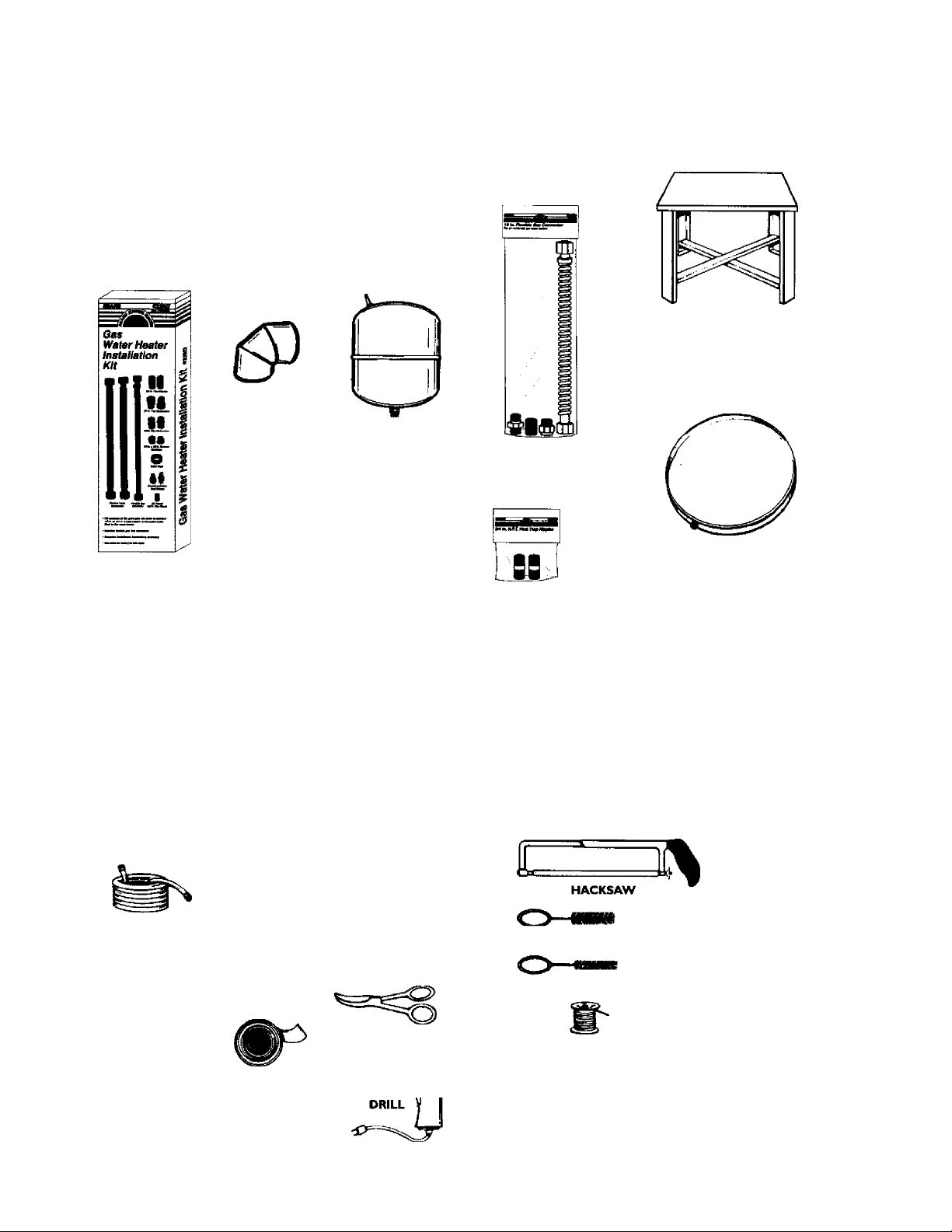
Materials and Basic Tools Needed
Materials Needed
To simplify the installation Sears has available the installation
parts shown below. You may or may not need all of these materb
als, depending on your type of installation.
WATER HEATER STAND 24"xl4"xl8"
FOR USE WITH WATER HEATERS
INSTALLED IN RESIDENTIAL
GARAGES HAVING A DIAMETER 24"
OR LESS AND A RATED CAPACITY
75 GALLONS OR LESS
VENT ELBOW
EXPANSION TANKS
FOR THERMAL
EXPANSION CONDI
TIONS AVAILABLE IN
2 GALLON AND 5
GALLON CAPACITY
THROUGH LOCAL
SEARS STORE OR
SERVICE CENTERS
WATER HEATER INSTAL
LATION KIT WITH FLEXI
BLE CONNECTORS FOR
3/4" OR 1/1" THREADED
OR COPPER PLUMBING
c
VENT PIPE
Basic Tools
You may or may not need ail of these tools, depending on your
type of installation. These tools can be purchased at your local
Sears store.
• Pipe Wrenches (2) 14"
• Screwdriver
• Tin Snips
• 6 Foot Tape of Folding Rule
• Garden Hose
•Drill
• Pipe dope or Teflon Tape
FLEXIBLE WATER
HEATER GAS CON
NECTOR WITH
FITTINGS
DRAIN PANS AVAILABLE IN 20" DIAME
WATER HEATER HEAT
TRAPS HELP REDUCE HEAT
LOSS DUE TO THERMAL
SYPHONING
TER FOR WATER HEATERS HAVING A
DIAMETER 18" OR LESS AND AVAIL
ABLE IN 28" DIAMETER FOR WATER
HEATERS HAVING A DIAMETER 26" OR
LESS
ADDITIONAL TOOLS NEEDED
WhlEN SWEAT SOLDERING
• Tubing Cutters or Hacksaw
• Propane Torch
• Soft Solder
• Solder Flux
• Emery Cloth
• Wire Brushes
CARDEN HOSE
SLOT-HEAD SCREWDRIVER
PHILLIPS SCREWDRIVER
PIPE DOPE (SQUEEZE TUBE)
(USE FOR WATER AND
GAS CONNECTIONS)
6 FOOT TAPE
ROLL OF TEFLON TAPE
(USE ONLY ON WATER
CONNECTIONS)
PIPE
WRENCH
TIN SNIPS
3/4" WIRE BRUSH
1/2" WIRE BRUSH
ROLL OF LEAD FREE
SOFT SOLDER
ROLL OF EMERY
CLOTH
SOLDER FLUX
PROPANE
TORCH
TUBING
CUTTER
Installation Instructions
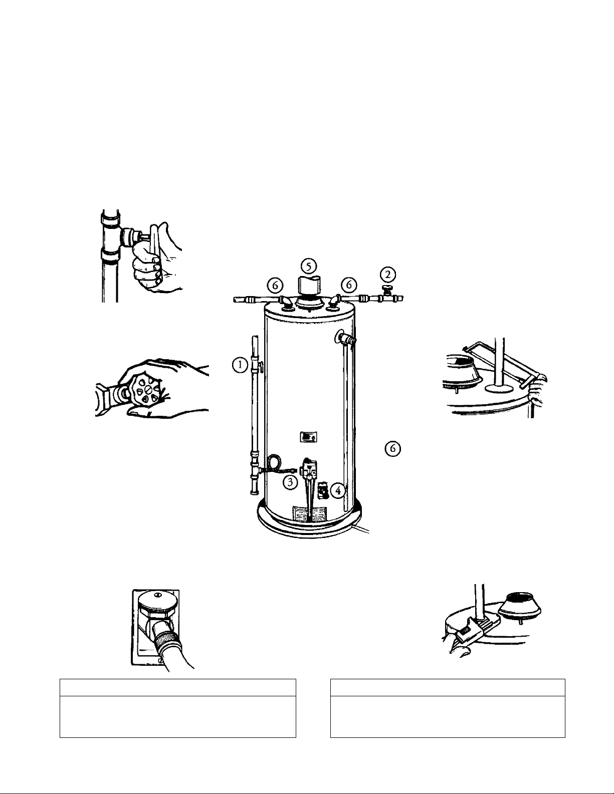
Removing the Old Water Heater
Turn “OFF” the gas supply to the water heater.
AWARNING
If the main gas line shutoff serving all gas appliances Is
used, al» shut “OFF" the gas at each appliance. Leave ^1
gas appliances shut “OFF" until the water heater installa
tion is complete.
Turn “OFF” the water to the water
©
heater. Some installations require that
the water be turned off to the entire
house.
/^Disconnect the vent pipe from the draft hood where
' they connect to the water heater. In most installations
the vent pipe can be lifted off after any screw or other
attached devices are removed. Dispose of the draft
hood. The new water heater has the draft hood which
must be used for proper operation.
. If you have copper piping to the water
©
heater, the two copper water pipes can be
cut with a hacksaw approximately 4"
away from where they connect to the
water heater. This will avoid cutting off
the pipes too short. Additional cuts can
be made later if necessary. Disconnect
the temperature-pressure relief valve
drain line. When the water heater is
drained, disconnect the hose from the
drain valve. Close the drain valve. The
water heater is now completely discon
nected and ready to be removed.
Check again to make sure the e« supply
(?)
is “OFF to the water heater. Then dis
connect the gas supply connection from
the gas control valve.
Attach a hose to the water heater drain
©
valve and put the other end in a floor
drain or outdoors. Open the water heater
drain valve. Open a nearby hot water
faucet which will relieve pressure in the
water heater and speed draining.
AWARNING
The water passing out of the drain valve may be extremely
trot To avoid being scalded, make sure all connections are
tight and that the water flow is directed away from any
person.
b. If you have galvanized pipe to the water
heater, loosen the two galvanized pipes
with a pipe wrench at the union in each
line. ATso disconnect the pming remain
ing to the water heater. These pieces
should be saved since they may be need
ed when reconnecting the new water
heater. Disconnea the temperature-pres
sure relief valve drain line. When the
water heater is drained, disconnect the
hose from the drain valve. Close the
drain valve. The water heater is now
completely disconnected and ready to be
removed.
ACAUTION
Mineral buildup or sediment may have accumulated in the
old water heater. This causes the water heater to be much
heavier than normal and this residue, if spilled out, could
cause staining.
8

Installation Instructions (cont’d)
Facts to Consider About the Location
You should carefully choose an indoor location for the new
water heater, because the placement is a very important consid
eration for the safety of me occupants in the building and for
the most economical use of the appliance. This water heater is
not for use in mobile homes or outdoor installation.
Whether replacing an old water heater or putting the water
heater in a new location, the following critical points must be
observed,
• The location selected should be indoors as close as practical
to the gas vent or chimney to which the water heater vent is
going to be connected, and as centralized with the water pip
ing system as possible. The water heater, as all water heaters,
will eventually leak. Do not install without adequate
drainage provisions where water flow will cause damage.
▲CAUTION
WATER HEATERS EVENTUALLY LEAK: Installation of the
vrater heater must be accomplished in such a manner that if
the tank or any connections stwuld leak, the flow of water wilt
not cause damage to the structure. When such locations can
not be avoided, a suitable drain pan should be installed under
the vrater heater. Drain pans are available at your local Sears
store. Such a drain pan must be not greater than I /> inches
deep, have a minimum length and width of at least 2 inches
greater than the water heater dimensions and must be piped
to an adequate drain. The pan must not restrict combustion air
flow. Under no circumstances is the manufacturer or Sears to
be held liable for any water dam^ in connection with this
water heater.
▲WARNING
INSTALLATIONS IN AREAS WHERE FLAMMABLE UQUIDS
(VAPORS) ARE LIKELY TO BE PRESENT OR STORED
(GARAGES, STORAGE, AND UTILITY AREAS, ETC);
Flammable liquids (such as gasoline, solvents, propane (LP) or
butane, etc.), all of which emit flammable vapors, may be
improperly stored or used in such areas. The gas water heftter
pilot light or main burt№r can ignite sudi vapors. The resulting
flashback and fire can cause death or serious bums to anyone in
the area, as well as property dam;^.
If kistailation in su^ areas is your only option, then the installa
tion must be accomplished in a way that the pilot flame and
main burner fiame are elevated from the floor at least 18 inches.
While this imqr reduce the chances of flammable vapors from a
floor spill being ignited, gasoline and other flammable substances
should never stored or used in the same room or area contaning a gas water heater or other open flame or spark produc
ing appliance.
NOTE; Flamm^le vapors may be drawn by air currents from
other ueas of the structure to the appliance.
▲WARNING
Propellants of aerosol sprays and volatile compounds, (clean
ers, chlorine based chemicals, refrigerants, etc.) in addition to
being hi^ly flammable in many cases, will also change to cor
rosive l^drochloric acid when exposed to the combustion
products of the vrater heater. The results can be hazardous,
and also cause product failure.
The location selection must provide adequate clearances for ser
vicing and proper operation of the water heater.
▲WARNING
This water heater must not be installed directly on carpeting.
Carpeting must be protected by a metal or wood panel
beneath the appliance extending beyond the full width and
depth of the appliance by at least 3 inches (76.2mm) in any
direction, or if tiie appliance is installed in an alcove or closet,
the entire floor must be covered by the panel. Failure to heed
this warning may result in a fire hazard.
▲WARNING
Minimum clearances between the water heater and com
bustiMe or non-combustible construction are I" at tiie sides
and rear, 4" at the front, and 6" from tiie vent pipe. Clearance
from the top of the jacket b 18" on most models. Note that a
lesser dimension may be allowed on some models. Refer to die
label on the water heater adjacent to the gas control valve for
ail clearances.
12'MAX,
T
VENTJ^TON
r MIN.
OPENINGS
Il0p^m.|
I mwwnilim I
12" MAX.
Figure I
AIR DUCT
▲WARNING
A gas water heater cannot operate properiy without the cor
rect amount of air for combu^on. Do not install in a confined
area such a doset, unless you provide air as shown in the “Facts
to Consider About the Location” section. Never obstruct the
flow of ventilation air. If you have any doubts or questions at all,
call your gas company. Failure to provide the proper amount of
combustion air can result in a fire or explosion and can cause
DEATH, SERIOUS BODILY INJURIT, OR PROPERTY DAMAGE
▲WARNING
If thb water heater will be used in beauty shops, barber shops,
cleaning establishments, or self-service laundries with dry
cleaning equipment, it b imperative that the water heater or
water heaters be installed so that combustion and ventilation
air be taken from outside these areas. Refer to the “Facts to
Consider About the Location” section of thb manual and also
the latest edition of the National Fuel Gas Code, ANSI Z223.I,
also referred to as NFPA 54 for specifics provided concerning
air required.

Installation Instructions (cont’d)
Combustion Air and Ventilation
for Appliances Located in
Unconfined Spaces
Unconfined Space is a space whose volume is not less than 50
cubic feet per 1,000 Btu per hour of the ^gregate input rating
of all appliances installed in that space. Rooms communicating
directly with the space in which the appliances are installed,
through openings not furnished with doors, are considered a
part of the unconfined space.
In unconfined spaces in buildings, infiltration may be adequate
to provide air for combustion, ventilation and dilution of flue
gases. However, in buildings of tight construction (for example,
weather stripping, heavily insulated, caulked, vapor barrier, etc.),
additional air may need to be provided using the methods
described in Combustion Air and Ventilation for Appliances
Located in Confined Spaces, b.
Combustion Air and Ventilation
for ^pliances Located in
Confined Spaces ,
Confined Space is a space whose volume is less than 50 cubic
feet per 1,000 Btu per hour of the aggregate input rating of all
appliances installed in that space,
a. ALL AIR FROM INSIDE BUILDINGS:
(See Page 9 Figure 1, and Figure 2 below)
The confined space shall be provided with two permanent
openiMs communicating directly with an additional room(s)
of sufficient volume so that the combined volume of all
spaces meets the criteria for an unconfined space. The total
input of all gas utilization equipment installed in the com
bined space snail be considered in making this determination.
Each opening shall have a minimum free area of one square
inch per 1,000 BTU per hour of the total input rating of all
gas utilization equipment in the confined space, but not less
than 100 square inches. One opening shall commence within
12" of the top and one commencing within 12" of the bot
tom of the enclosure.
« tiMHfY 0Ц QM VEHT
1. When directly communicating with the outdoors, each open
ing shall have a minimum free area of 1 square inch per 4,000
BTU per hour of total input rating of all equipment in the
enclosure. (See Figure 3.)
2. When communicating with the outdoors through vertical
ducts, each opening shall have a minimum free area of 1
square inch per 4,000 BTU per hour of total input rating of
all equipment in the enclosure. (See Figure 4.)
Figure 4
3. When communicating with the outdoors throu^ horizontal
ducts, each opening shall have a minimum free area of 1
square inch per 2,000 BTU per hour of total input rating of
all equipment in the enclosure. (See Figure 5.)
Figure 5
-CHWNev OH <i*S VENT
OOTLET AIR CUCI
MLETMRDUCl
Figure 2
m
ALL AIR FROM OUTDOORS: (see Figures 3-5)
The confined space shall be provided with two permanent
openings, one commencing within 12" of the top and one
commencing within 12" from the bottom of the enclosure.
The openings shall communicate directly, or bj ducts, with
the outdoors or spaces (crawl or attic) that freely communi
cate with the outdoors.
Figure 3
4. When ducts are used, thev shall be of the same cross-sectional
area as the free area of the openings to which they connect.
The minimum short side dimension of rectangular air ducts
shall not be less chan 3". (See Figure 5-)
5. Louvers and Grilles: In calculatiim free area, consideration
shall be given to the blocking effect of louvers, grilles or
screens protecting openings. Screens used shall not be smaller
than V* mesh. If the free area through a design of louver or
grille is known, it should be used in ^dilating the size open
ing required to provide the free area specified. If the design
and free area is not known, it may be assumed that wood lou
vers will be 20-25 percent free area and metal louvers and
grilles will have 60-75 percent free area. Louvers and grilles
shall be fixed in the open position or interlocked with the
equipment so that they are opened automatically during
equipment operation.
6. Special Conditions Created by Mechanical Exhausting or
Fireplaces: Operation of exhaust fans, ventilation systems,
clothes dryers or fireplaces may create conditions requiring
special attention to avoid unsatisfactory operation of installed
gas utilization equipment.
10

Installation Instructions (cont’d)
Water Piping
AWARNING
HOTTER WATER CAN SCALD: Witer heaters are intended to
produce hot water. Water heated to a temperature which wiii
satisfy dothes washing, dish washing, and otter sanitizing needs
can scaid and permanently injure you upon contact Socne peo
ple are more likely to be permanently injured by hot water than
others. These include the etdeiiy, children, the Mrm, or physically/mentally handicapped. If anyone using hot water in your home
fits into one of these groups or if there is a local code or state law
requiring a certain temperature water at the hot water tap, then
you must tate special precautions. In addition to using the lowest
possible temperature setting that satisfies your hot water needs,
a means such as a mixing valve, should be used at the hot water
taps used by these people or at the water heater. Mixing valves
are available at plumbing supply or hardvrare stores. Follow man
ufacturers instructions for installation of the valves. Before
changing the factory setting on the thermostat, read the
‘Temperature Regulatíon" section in this manual.
AWARNING
This water heater shall not be connected to any
heating systems or component(s) used with a non
potable water heating appliance.
AWARNING
Toxic chemicals such as used for treatment of boilers
or non-potable water heating appliances shall never
be introduced into a potable water heating system.
Look at the top cover of the water heater. The cold water
inlet is marked cold. Put two or three turns of teflon tape
around the threaded end of the threaded-to-sweat coupling
and around both ends of the threaded nipple. Using flexi
ble connectors, connect the cold water pipe to the cold water
inlet of the water heater,
NOTE: This water heater is super insulated to minimize
heat loss from the tank. Further reduction in heat loss
can be accomplished by insulating the hot water lines
from the water heater.
INSTALLATION COMPLETED USING
SEARS INSTALLATION KIT
SHUTOFF
If a water heater is installed in a closed water supply system;
such as one having a back-flow preventer, check t^ve, wafer
meter with a check valve, etc... in the cold water supply; means
shall be provided to control thermal expansion. Contact the
local utility or local Scars Service Center on how to control this
NOTE: To protect against untimely corrosion of hot and
cold water fittings, it is strongly recommended that di-elec
tric unions or couplings be installed on this water heater
when connected to copper pipe.
The illustration shows the attachment of the water piping to the
water heater. The water heater is equipped with Vt water
connections.
NOTE: If using copper tubing, solder tubing to an adapter
before attaching the adapter to the cold water inlet connec
tion. Do not solder the cold water supply line diiecdy to the
cold water inlet. It will harm the dip tube and damage the
tank.
• Look at the top cover of the water heater. The water oudet is
marked hot. Put two or three turns of teflon tape around the
threaded end of the threaded-to-sweat coupling and around
both ends of the M" threaded nipple. Using flexible connec
tors, connect the hot water pipe to the hot water outlet on
the water heater.
11

Installation Instructions (cont’d)
Temperature-Pressure Relief Valve
AWARNING
At the time of manufacture this water heater was provided
with a combination temperature-pressures reiief valve certified
by a nationally recognized testing laboratory that maintains
periodic inspection of production of listed equipment or mate
rials, as meeting the requirements for Relief Valves and
Automate Gas Shutoff Devices for Hot Water Supply Systems,
and the latest edition of ANSI 221.22 and the code require
ments of ASME. If replaced, the valve must meet the require
ments of local codes, but not less than a combination tempera
ture and pressure relief valve certified as meeting the require
ments for Relief Valves and Automatic Gas Shutoff Devices for
Hot Water Supply Systems, ANSI Z2I.22 by a nationally recog
nized testing laboratory that maintains periodic infection of
production of listed equipment or materials.
The valve must be mariœd with a maximum set pressure not
to exceed the marked hydrostatic working pressure of the
vrater heater (ISO IbsJsq. in.) and a discharge capacity not less
than the water heater input rate as shown on the model rating
plate. (Electric heaters - watts dividecl by 1000 x 3415 equal
BTU/Hr. rate.)
Your local jurisdictional authority, while mandating the use of a
temperature-pressure relief valve complying with ANSI Z2I.22
and ASME, may require a valve model different from the one
furnished with die water heater.
Compliance with such local requirements must be satisfied by
the installer or end user of the water heater with a locally pre
scribed temperature-pressure relief valve installed in the desig
nated opening in the water heater in place of the fiictory fur
nished valve.
For safe operation of the water heater, the relief valve must not
be removed from № designated opening or plugged.
The temperature-pressure relief ràlve must be installed directly
into the fitting of the water heater designated for the relief valve.
Position the v^ downward and provide tubing so that any dis
charge will exit only within 6 inches above, or at any distance
below the structural floor. Be certain that no contact is made
with any live electrical part The discharge opening must not be
blocked or reduced in size under any circumstances. Excessive
length, over 30 feet, or use of more than four elbows can cause
restriction and reduce the discharge capacity of the valve.
No valve or other obstruction is to be placed between the relief
valve and the tank. Do not connect tubing directly to discharge
drain unless a 6" air gap is provided. To prevent bodily Injury, haz
ard to life, or property damage, the relief valve must be allowed
to discharge vrater in quantities should circumstances demand. If
the discharge pipe is not connected to a drain or other suitable
means, the water flow may cause property damage.
The Discharge Pipe:
* Must not be smaller in size than the outlet pipe size of the
valve, or have any reducing couplings or other restrictions.
* Must not be plumed or blocked.
* Must be of material listed for hot water distribution.
* Must be installed so as to allow complete drainage of both
the temperature-pressure relief valve, and the discharge
pipe.
* Must terminate at an adequate drain.
* Must not have any valve between the relief valve and tank.
AWARNING
The temperature-pressure relief valve must be manually
operated at least once a year. Caution should be taken to
ensure that (I) no one is in front of or around the outlet of
the temperature-pressure relief valve discharge line, and (2)
the water manually discharged will not cause any bodily
injury or property damage because the water may be
extremely hot
If after manually operating the valve, it foils to completely
reset and continues to release water, immediately dose the
cold water inlet to the water heater, follow the draining
instructions, and replace the temperature-pressure relief
valve with a new one.
SHUTOFF COLD
VALVE
TEMPERATURE-
PRESSURE
RELIEF VALVE
DISCHARGE PIPE
(Do not cap or piug)
6” AIR GAP
RELIEF VALVE OPENING
At the time of nunuficture, this water heater was providetl with a combinatìon tem
perature-pressure relief valve listed as complying with the standard for relief valves and
automatic gas shut-off devices for hot water suppiy systems, ANSI Z2I.22. For safe
operation of the water heater, the relief vaive must not be removed from its designated
point of installadon or plugged.
Tour local jurisdictional authority, while mandating the use of a temperature-pressure
relief valve compijnng with ANSI Z21.22 and ASME, msy require a valve model different
from the one furnished with the water heater.
Compliance with such local requirements must be sadslied by the installer or end user
of the water heater with a locally prescribed temperature-pressure relief valve installed
in the designated opening In the water heater.
See manual heading -‘Temperature-Pressure Relief Valves" for installation and mainte
nance of relief valve, discharge line, and other safety precautions.
12

Installation Instructions (cont’d)
Filling the Water Heater
A CAUTION
Never use this water heater unless it is completeiy filied with
water. 1b prevent damage to the tank, the tank must be liiled
with vrater. Water must flow from the hot water faucet
before turning "ON” gas to the water heater.
To fill the water heater with water:
• Close the water heater drain valve by turning the handle to
the right (clockwise). The drain valve is on the lower firont of
the water heater,
• Open the cold water supply valve to the water heater.
NOTE: The cold water supply valve must be left open
when ¿e water heater is in use.
• To insure complete filling of the tank, allow air to exit by
opening the nearest hot water faucet. Allow water to run
until a constant fiow is obtained. This will let air out of the
water heater and the piping.
• Check all new water piping for leaks. Repair as needed.
Venting
AWARNING
VENT DAMPERS - Any vent damper, whether it is operated
thermally or otherwise must be remov^ if its use inhibits prop
er drafting of the water heater.
Thermally Operated Vbnt Dampers: Gas-fired water heaters
hawing thermal efficiency in excess of 80% may produce a rela
tively kw flue gas temperature. Such temperatures may not be
high enough to properly open thermally operated vent
dampers. This would cause spillage of flue gases and may cause
carbon monoxide poisoning.
>fent dampers must bear evidence of certification as complying
with the latest edition of American National Standard ANSI
Z2I.68 (ANSI Z2I.66 & 67, respective, cover electrically and
mechanically actuated vent danripers). ElA>re installation of any
vent damper, consult your local Sevs Serdce Center or the gas
utility for further infomation.
AWARNING
To insure proper venting of this gas-fired water heater, the
correct vent pipe diameter must be utilized. Any additions or
deletions of other gas appliances on a common vent with this
water heater may advenety affect the operation of the water
heater. Consult the local Sears Service Center or gas utility if
any such changes are planned.
For proper venting in certain installations, a larger diameter vent
pipe may be necessary. Due to great variances in installations,
unforeseeable by the manufiicturer of the water heater, you must
consult your gas company to aid you in determining the proper
venting for your water heater from the vent tables m the latest
edition of the National Fuel Gas Code ANSI Z223.1, also
referred to as NFPA 54.
Check the venting system for signs of obstruction or deteriora
tion and replace if needed.
The combustion and ventilation air flow must not be obstructed.
AWARNING
Obstructed or deteriorated vent systems may present a serious
health risk or asphyxiation.
Place the draft hood legs in the receiving holes on the top of
the water heater. The legs wiU snap in the holes to give a tight
fit.
Place the vent pipe over the draft hood. With the vent pipe in
position, drill a small hole through both the vent pipe and
draft hood. Secure them together with a sheet metal screw.
DRAFT HOOD ^ VENT,
DRAFT
'si I 4'
SCRE
VENT TO OUTDOORS OR
CHJMNEY
AWARNING
The water heater with draft hood installed must be properly
vented to a chimney which terminates outdoors. Never opei^
ate the water heater unless it is vented to the outdoors and has
adeqw^ air supply to avoid risks of improper operation, explo
sion or asphyxiation.
AWARNING
The vent pipe from the water heater must be no less than the
diameter of the draft hibod outlet on the water heater, and
must slope upward to the chimney at least inch per linear
foot
DRAFT HOOD
13

Installation Instructions (cont’d)
Venting (cont’d)
All vent gases must be completely vented to the outdoors of the
structure (dwelling). Install only the draft hood provided with
the new water heater and no other draft hood.
Vent pipes must be secured at each joint with sheet metal screws.
VENT PIPE INSTALLATION
There must be a minimum of 6" clearance between single wall
vent pipe and any combustible material. Fill and seal any clear
ance oetween single wall vent pipe and combustible material
with mortar mix, cement, or other noncombustible substance.
For other than single wall, follow vent pipe manufteturer’s clear
ance speciGcations. To insure a tight fit of the vent pipe in a
brick chimney, seal around the vent pipe with mortar mix
cement.
AWARNING
Failure to have required clearances between vent piping and
combustible material will result In afire hazard.
AWARNING
Be sure vent pipe Is properly connected to prevent escape of
dangerous flue gases which could cause deadly asphyxiation.
Gas Piping
AWARNING
Make sure the gas supplied is the same type listed on the
mod^ rating plate. The inlet gas pressure must not exceed
10.5 in. voter column (2.6kPa) for natural gas or 13 in. water
column (3.2kPa) for propane (LP.) gas. The minimum inlet
gas pre^re listed on the moM rating plate is for the pur
pose of input adjustment.
__________
H the gas control valve is subjected to pressures exceeding 'A
pound per square inch (3.5k^), the dam^ to the gas con
trol vaho could result in a fire or explosion ^m leaking gas.
K the main gas line shutoff serving all gas apfriiances is used,
also turn “OFP’ ^ gas at each a^iance. Lem all gas appli
ances shut off until the water heater installation is complete.
A gas line of sufficient size must be run to the water heater.
Consult the latest edition of National Fuel Gas Code ANSI
Z223.1, also referred to as NFPA54 and the gas company concern
ing pipe size.
There must be:
• A readily accessible manual shut off valve in the gas supply line
serving the water heater, and
• A drip leg (sediment tr^) ahead of the gas control valve to help
prevent dirt and fere^ materials from entering the gas control
valve.
• A flexible gas connector or a ground joint union between the
shutoff valve and control valve to permit servicing of the unit.
Be sure to check all the ^ piping for leaks before lighting the
water heater. Use a soapy water solution, not a match or open
flame. Rinse off soapy solution and wipe dty.
AWARNING
AWARNING
_________________
_________________
^
^
AWARNING
Chemical vapor corrosion of the flue and vent system may
occur if air for combustion contains certain chemical vapors.
Spray can propellants, cleaning solvents, refrigerator and air
conditioner refrigerants, swimming pool chemicals, calcium
and sodium chioride, waxes, bleadi, and process chemicals are
typical compounds which are potentially corrosive.
Standanl Modds are for installadon up to 3,300 feet above sea
level.
Altitude Models are for installation from 3,300 to 5,500
feet above sea level.
If a standard model is installed above 3,300 feet or a high altitude
model is installed above 5,500 feet, the input rating must be
reduced at the rate of 4 percent for each 1,000 feet above sea level.
Contact your local Sears Service Center or gas utility for further
information.
AWARNING
The appliance and its gas connection must be leak tested
before placing the appliance in operation.
14

Installation Instructions (cont’d)
______________
• The appliance and its individual shutoff valve must be discon^
nected from die gas supply piping system durii^ any pressure
testing of the gas system at test pressures in excess of '/i
pound per square indi (3.5kPa).
• The appliance must be isolated from the gas supply piping sys
tem by doting its individual manual shutoff valve during any
pressure testing of the gas supply piping system at test pres
sures equal or less than Yt pound per square inch (3.5kPa).
Use pipe joint compound or teflon tape marked as being
resistant to the action of petroleum [Propane (LR)] gases.
SEDIMENT TRAP
A sediment trap shall be installed as cldse to the inlet of the
water heater as practical at the time of water heater installation.
The sediment trap shall be either a tee fitting with a capped nip
ple in the bottom outlet or other device recognized as an effec
tive sediment trap. If a tee fitting is used, it shall be installed in
conformance with one of the methods of installation shown
below.
Connecting the gas piping to the gas control valve of the water
heater can be accomplished by either of the two methods shown.
Contaminants in the gas lines may cause improper operation
of the gas control valve that may result in fire or ei^osion.
Before attaching the gas line be sure that all gas pipe is dean
on the inside, lb trap any dirt or foreign material in the gas
supply line, a drip leg (sometimes called a sediment tr^)
must be incorporated in the piping. The drip leg must be
readily accessible. Install In accordance with the *'&s Piping”
section. Refer to the latest edition of the National Fuel Gas
Code, ANSI Z223.I, also referred to as NFRA 54.
A WARNING
AWARNING
AWARNING
________________
_________
GAS PIPING WITH
FLEXIBLE CONNECTOR
FLEXIBLE GAS CONNECTOR
I CONTROL
GAS PIPING WITH ALL BLACK IRON
PIPE TO GAS CONTROL
GAS
¡CONTROL
VALVE
GAS
VALVE
15

Installation Instructions (cont’d)
Installation Checklist
BEFORE LIGHTING THE PILOT:
• Check the gas lines for leaks.
a. Use a soapy water solution. DO NOT test for gas leaks
using a match or open ñame.
b. Brum the soapy water solution on all gas pipes, joints and
ñttings.
c ChecK for bubbling soap. This means you have a leak.
Turn “OFF” gas ana make the necessary repairs.
d. Recheck for leaks.
e. Rinse off soapy solution and wipe dry.
• Is the new temperature-pressure relief valve properly installed
and piped to an adequate drain? See “Temperature-Pressure
Relief Valve” section.
• Are the cold and hot water lines connected to the water
heater correctly? See “Water Piping” instructions in the
“Installation Instructions” section.
• Is the water heater completely filled with water? Sec “Filling”
instructions in the “installation Instructions” section.
• Will a water leak damage anything? See the “Facts to
Consider About the Location” section.
Is there proper clearance between the water heater and any
" ' that might catch ^ ~ ‘ ' ''
thing that might catch fire? See the “Facts to Consider About
Dcation” section.
the Loc ' " '
Do you have adequate ventilation so that the water heater
will operate properly? See “Combustion Air and Ventilation”
in the “Facts to Consider About the Location” section.
VENT PIPE TO
OUTDOORS
OR CHIMNEY SHUTOFF VALVE
Is the draft hood vent piping properly secured? See “Venting”
. . . „ piping. . .
instructions in the “Installation Instructions” section.
• Is there proper clearance between the vent pipe and anything
that mi^t catch on fire? See “Venting” instructions in the
“Installation Instructions” section.
• Is the vent pipe properly sloped and does the vent terminate
outdoors? See “Venting” instructions in the “Installation
Instructions” section.
• Do you need to call your gas company to check the gas pipe
and its hookup?
•
16

Operating Instructions
Lighting
AWARNING
BEFORE LIGHTING [PROPANE (LP.) GAS WATER
HEATERS]: Propane (LR) gas is heavier than air. Should there
be a leak in the system, the gas will settle near the ground.
Basements, crawl spaces, skirted areas under mobile homes
(even when ventilated), closets and areas bekw ground level will
serve as pockets for the accumulation of this gas. Before
attNTipting to light or relight the water heaterb pilot or turning
on a nearby eiedrical light switch, be absolutely sure there is no
accumulated gas in the area. Sear^ for odor of gas by sniffing at
ground level in the vicinity of the appliance. If odor is detected,
follow steps indicated at “For Your Safety” on the cover page of
this manual then leave the premises.
Lighting and operating instructions are located on front of the
water heater, above or to one side of the gas control valve.
AWARNING
AN ODORANT IS ADDED TO THE GAS USED
BY THIS WATER HEATER.
FOR YOUR SAFETY
IF YOU SMELL GAS:
Do not try to light any appliance.
Do not tMJch any electrical switch; do not use any phone in
your buiiding.
• Immediateiy call your gas supplier from a neighbor^ phone.
Follow the gas suppliei^ instructions.
If you cannot reach your gas supplier, call the fire depart
ment.
Figure 6
Figure 7
AWARNING
DO NOT force the gas contnri knob. Use only your hand to
push it down to light the pilot, or to turn it to “ON”, “OFF”
or “PILOT’. Never use a tool such as a lever, wrench or pli
ers. Do not hit or damage the knob. A damaged knob may
result in an explosion and serious injury. If you have problem
turning the loiob, call the gas supplier immediately.
CHECK FOR LEAKS
Be sure to check all your gas pipes for leaks before lighting your
water heater. Use a soapy water solution, not a match or open
flame. Check the factory gas fittings after pilot is lit and gas con
trol knob is still in “PILOT” position. Then, check the fittings
when the main burner is turned “ON”. Use a soapy water solu
tion for this, too.
Figure 8
17

Operating Instructions (cont’d)
Lighting label on the water heater as it appears above the thermostat
FOR YOUR SAFETY READ BEFORE LIGHTING
If you do not follow these instructions exactiy, a fire or explosion
may result causing property damage, personai injury or ioss of ilfe.
A. This appiiance has a piiot which must be iighted by
hand. When iighting the pilot, follow these instructions
exactly.
B. BEFORE LIGHTING smell all around the appliance area
for gas. Be sure to smell next to the floor because
some gas is heavier than air and will settle on the floor.
WHAT TO DO IF YOU SMELL GAS
* Do not try to light any appliance.
* Do not touch any electric switch; do not use any
phone in your building.
* Immediately call your gas supplier from a neighbor’s
phone. Follow the gas supplier’s instructions.
LIGHTING INSTRUCTIONS
WARNING
1. STOP! Read the safety information above on this label.
2. Remove outer door.
3. Set the thermostat to lowest settli^by turning the
water temperature dial clockwise, ('''> ) to Its lowest
temperature setting (with arrow on dial] as shown. DO
NOT FORCE.
4. Turn gas control knob clodcwise * to “OFF” posi
tion. Knob cannot be turned from “PILOT” to “OFF”
unless knob is depressed slightly. DO NOT FORCE.
(Figure 6, page 17)
5. Wait five (5) minutes to clear out any gas. If you then
smell gas, STOP! Follow “B” in the safety information
above on this label. If you don’t smell gas, go to the
next step.
6. Remove (or open) inner door located below the gas
control unit
7. Find pilot-foilow metal tube from gas control. The pilot
is located in front of the burner.
PILOT BURNER
THERMOCOUPLE
£l
8. If you don’t smell gas, turn knob on gas control counter
clockwise^ to “PILOT” position. (Figure 7, page 17)
* If you cannot reach your gas supplier, call the fire
department.
C. Use only your hand to push in or turn the gas control
knob. Never use tools. If the knob will not push in or
turn by hand, don’t try to repair it, call a qualified ser
vice technician. Force or attempted repair may result
In a fire or explosion.
D. Do not use this appliance if any part has been under
water. Immediately call a qualirM service technician
to inspect the appliance and to replace any part of the
control system and any gas control which has bwn
under water.
9. Push in control knob all the way and hold down.
Immediately light the pilot virlth a match. Continue to
hold control knob in for about one (1) minute after
the pilot is lit Release knob and it will pop back up.
Pilot should remain lit ff it goes out, repeat steps 3
through 8.
* If knob does not pop up when released, stop and
immediately call your service technician or gas
supplier.
* If the pilot will not stay tit after several tries,
depress and turn the gas control knob clockwise
) to “OFF” and call your service technician
or gas supplier. (Figure 6, page 17)
10. Replace (or dose) inner door. Replace outer door if
door does not cover gas control on/off knob or tem
perature adjustment knob. (Figure 9, page 17)
11. At arms lengfri away, turn gas control knob counter-
dockwise to the full “ON” position. Warning
do not use gas control knob to regulate gas
flow. (Figure 8, page 17)
12. At arms length away, set the thermostat to desired
setting. The mark (A) HOT indicative of approximate
120°F is preferred starting point. Some local laws
may require a tower starting point, if hotter water is
desired, see Instruction manual and “warning” below.
13. Replace the outer door if not replaced in step 10.
WARNING
Hotter water increases the risk of scald Injury. Before changing temperature setting see Instruction manual.
TO TURN OFF GAS TO APPLIANCE
1. Set the thermostat to lowest setting by turning the
water temperature dial dockwise (/^) to Its lowest
temperature setting (with arrow on dial) as shown. DO
NOT FORCE.
2. Turn gas control knob dockunse J to “OFF’ posi
tion. Knob cannot be turned from “PILOT” to “OFF”
unless knob is depressed slightly. DO NOT FORCE.
3. Replace outer door (if removed).
18

Operating Instructions (cont*d)
Temperature Regulation
Due to the nature of the typical gas water heater, the water tem
perature in certain situations may vary up to 30°F higher or
lower at the point of use such as, bathtubs, showers, sink, etc.
This means that when the temperature adjustment dial is set at
the mark approximating 120°F, the actual water temperature at
any hot water tap could be as high as 150°F or as low as 90“F.
Any water heater’s intended purpose is to heat water. Hot water
is needed for cleaning {bodies, dishes, clothing). Hot water will
present a scald hazard. Depending on the time element, and the
people involved (normal adults, children, toddlers, elderly,
infirm, etc.) scalding may occur at different temperatures.
AWARNING
HOTTER WATER CAN SCALD: Wtter heaters are intended to
produce hot water. Water heated to a temperature which will
satisfy clothes washing, dish washing, and other sanitizing needs
can scald and permanently injure you upon contact. Sotne peo
ple are more lilceiy to be permanentiy injured by hot water than
others. These include the elderly, children, the infirm, or physical-
ly/mentally handicapped. K anyone using hot water in your home
fits into one of these groups or if there is a local code or state law
requiring a certain temperature ¥rater at the hot voter tap, then
you must take spedal precautions. In addition to using the lowest
possible temperature setting that satisfies your hot water needs,
a meaiu such as a mbdng valve, should be used at the hot water
taps used by these peo|^ or at the water heater. Mbdng valves
are available at plumbing supply or hardware stores. Follow man
ufacturers instructions for installation of the valves. Before
changing the factory setting on the thermostat, read the
**Temperature Regulation” section in this manual.
Turn the water temperature dial clockwise ^) to decrease
the temperature, or counterclockwise to increase the
temperature.
PILOT LIGHTING-Sct here before attempting to light pilot.
A HOT-Is a thermostat setting of approximately
120°F, which will supply hot water at the
most economical temperatures. The
temperature adjustment knob can be
turned lower than “HOT” if desired.
A-Is a thermostat setting of approximately
130°F.
B—Is a thermostat setting of approximately
140“F.
AWARNING
Newer allow small children to use a hot water tap, or to draw
their own bath water. Never leave a child or handicapped per
son unattended in a bathtub or shower.
The thermostat of this water heater has been fectory set at its
lowest position, to reduce the risk of scald injury. It is adjustable
and must be reset to the desired temperature setting. The mark
(▲) HOT indicative of approximately 120°F is the preferred
starring point. Some states nave a requirement for a lower set
starring point. Some states have a requirement for a lower setting. If you need hotter water, follow directions for temperature
adjustment, but beware of the warnings in this section.
- . . . . ' ‘
C-Is a thermostat setting of approximately
ISO'E
VERY HOT-Is a thermostat setting of 160“F. It is
recommended that the dial be set lower
whenever possible.
NOTE: Water temperature range of 120°—140°F recom
mended by most dishvrashcr manufficturets.
AWARNING
Should overheating occur or the gas supply fail to shut off,
turn “OFF’ the manud gas control valve to the appliance.
19

Service and Adjustment
Tank (Sediment) Cleaning
Sediment build-up on the tank bottom may create varying
amounts of noise, and if left in the tank will cause premature
tank failure. In some water areas, you may not be able to drain
all sediment deposits by simply draining the tank. In these cases
Mag
Erad (part no. 23600) can be used to help remove the sedi
ment deposits. This may be ordered from the Sears Service
Center. For ordering, refer to the “Parts Order List” section.
Venting System Inspection
At least once a year a visual inspection should be made of the
venting system. You should look for:
* Obstructions which could cause improper venting. The com
bustion and ventilation air flow must not be obstructed.
* Damage or deterioration which could cause improper vent
ing or leaks^e of combustion products.
* Rusted flakes around top of water heater.
▲WARNING
Chemical vapor corrosion of the flue and vent system may
occur if air for combustion contains certain chemical vapors.
Spray can propellants, cleaning solvents, refrigerator and air
conditioner refri^rants, swmming pool chemicals, calcium
and sodium chloride, waxes, bleach, and process chemicals are
typical compounds v^ich are potentidly corrosive.
▲WARNING
Obstructed or deteriorated vent systems may present a serious
health risk or asphyxiation.
Burner Inspection
▲WARNING
Do not use this appliance if any part of it has been under water.
Imniediately call a Sears Service Technician to inspect the
appliance and to replace the gas control or any part of the
burner system which has been under vrater.
At least once a year a visual inspection should be made of the
main burner and pilot burner. The drawing is for your reference.
You should check for sooting which is not normal and will
impair proper combustion.
▲WARNING
Soot build-up indicates a problem diat requires correction
before further use. Turn “OFF” gas to water heater and leave
“OFF” until repairs are made, becuise foilure to correct the
cause of the sooting can result in a fire or explosion causing
DEATH, SERIOUS BODILY INJURY, OR PROPERTY DAMAGE.
^
_____________
Be sure the vent piping is properly connected to prevent
escape of dangerous flue gasses which could cause deadly
asphyxiation.
▲WARNING
_______________
▲WARNING
If after inspection of the vent system you found sooting or
deterioration, something b wrong. Call the local gas utility to
correct the problem and dean or replace the flue and venting
before resuming operation of the water heater.
Burner Cleaning
^
In the event your burner needs cleaning, use the following
instructions:
If inspection of the burner shows that cleaning is required, turn
the gas control knob clockwise to the “OFF” position,
depressing slighdy.
NOTE; The knob cannot be tumed from “PILOT” to “OFF”
unless knob is depressed slightly. DO NOT FORCR
Loose deposits on or around the burner can be removed by carefiilly using the hose of a vacuum cleaner inserted through the
access door of the water heater. If the burner needs to be removed
for additional cleaning, call the Sears Service Center to remove
and clean the burner and correa the problem that required the
burner to be cleaned.
20

Service and Adjustment (cont’d)
Draining
The water heater should be drained if being shut down during
freezing temperatures. Also periodic draining and cleaning of
sediment from the tank may be necessary.
• Turn the gas control knob to the “OFF” position.
• CLOSE the cold water inlet valve to the water heater.
• OPEN a nearby hot water faucet and leave open to allow for
draining.
• Connect a hose to the drain valve and terminate to an
adequate drain.
• OPEN the water heater drain valve to allow for tank
draining.
NOTE: If the water heater is ^ing to be shut down and
drained for an extended period, the drain valve should be
left open with hose conn«:ted allowing water to terminate
to an adequate drain.
• Close the drain valve,
• Follow instructions in the “Filling The Water Heater”
section.
• Follow the lighting instructions in the “Lighting” section to
restart the water heater.
Temperature-Pressure Relief
Valve Operation
The temperature-pressure relief valve must be manually operated
at least once a year.
ТЕМ PERATURE-PRESSURE
Drain Valve Washer
Replacement
NOTE: For replacement “se a i i VI" thick washer
available at your nearest hardware store. For ordcrii^ replace
ment vrashers, refer to the “Parte Order List” section.
• Turn “OFF” gas supply to water heater.
• Follow “Draining" instructions.
• Turning counter clockwise, remove the hex cap below the
screw handle.
• Remove the washer and put the new one in place.
• Screw the handle and cap assembly back into the drain valve
and reti^ten using a wrench. DO NOT OVERTIGHTEN.
• Follow instructions in the “Filling The Water Heater”
section.
• Check for leaks.
• Follow the lighting instrnctions in the “Lighting” section to
restart the water heater.
Failure to install and maintain a new properly listed tempera
ture-pressure relief valve will release the manufacturer from any
claim which might result from excessive temperature or pressure.
AWARNING
If rite temperature-pressure relief valve on the appliance
weeps or disdiarges periodically, this may be due to thermal
expansion. Your water heater may have a check valve
in^led in the water line or a water meter with a check
valve. Consult the Sears Service Center for further informa
tion. Do not plug the temperature-pressure relief valve.
AWARNING
When checking Ihe temperatureqjressure rdief valve opera
tion, make sure that (I) no one is in front of or around the
outlet of the tempera№re-pressure relief valve discharge line,
and (2) that the water manually discharged will not cause any
property dami^ because the water may be extremely hot
if after manually operating the valve, it fails to completely
reset and continues to release water, immediately close the
cold water inlet to the water heater, follow the draining
instructions, and replace the temperature-pressure relief
valve with a new one.
Vacuum around base of water heater for dust, dirt, and lint on a
regular basis.
______________
INSTALLED IN SUITABLE AREA: To insure sufficient vetitih
lation and combustion air supply, proper clearances fiwn the
water heater must be maintained. See “Facts to Consider
About the Location” section. Combustible materials such as
clothing, denting materials, or flammable liquids, etc.
not be placed against or adjacent to the water heater which
can cause afire.
AWARNING"
________________
Service
Before calling for repair service, read the “Start Up Conditions”
and “Operational Conditions” found in the Troubleshooting
Guide of this manual.
If a condition persists or you are uncertain about the operation
of the water heater, let a qualified person check it out.
Contact SEARS Repair Services at 1-800-4-MY-HOME
(1-800-469-4663).
21
^

Troubleshooting Guide
Start Up Conditions
CONDENSATION
Whenever the water heater is filled with cold water, a certain
amount of condensation will form while the burner is on. A
water heater may appear to be leaking when in fact the water is
condensation. This usually happens when:
• When a new water heater is filled with cold water for the
first time.
• When gas burns and water vapor is produced in water
heaters, particularly high efficiency models where flue tem
peratures are lower.
• When you use large amounts of hot water in a short time
and the refill water is very cold.
Moisture from the products of combustion condense on the
cooler tank surfaces and form drops of water which may fall
onto the burner or other hot surfiiccs to produce a “siizling” or
“fiying” noise.
Excessive condensation can cause pilot outage due to water run
ning down the flue tube onto the main burner and putting out
the pilot.
Because of the suddenness and amount of water, condensation
water may be diagnosed as a “tank leak”. After the water in the
tank warms up (about 1-2 hours), the condition should
disappear.
Do not assume the water heater is leaking until there has been
enough time for the water in the tank to warm up.
An undersized water heater will cause more condensation. The
water heater must be sized properly to meet the family’s
demands for hot water including dishwashers, washing machines
and shower heads.
Excessive condensation may be noticed during the winter and
early spring months when incoming water temperatures are at
their lowest.
Good venting is essential for a gas fired water heater to operate
properly as well as to carry away products of combustion and
water vapor.
SMOKE/ODOR
It is not uncommon to experience a small amount of smoke and
odor during the initial start-up. This is due to burning off of oil
from metal parts, and will disappear in a short while.
THERMAL EXPANSION
Water supply systems may, because of high line pressure, fre
quent cut-offs, the effects of water hammer and others, have
installed devices such as pressure reducing valves, check valves,
back flow preventers, etc. to control these types of problems.
When these devices are not equipped with an internal by-pass,
and no other measures are taken, the devices cause the water sys
tem to be closed. As water is heated, it expands (thermal expan
sion) and closed systems do not allow for the expansion of heat
ed water.
The water within the water heater tank expands as it is heated
and increases the pressure of the water system. If the relieving
point of the water heater’s temperature-pressure relief valve is
reached, the valve will relieve the excess pressure. The tempera-
turc^mressure relief valve is not intended for the constant
relief of thermal expansion. This is an unacceptable condition
and must be corrected.
It is recommended that any devices installed which could create
a closed system have a by-pass and/or the system have an expan
sion tank to relieve the pressure built by thermal expansion in
the water system. Expansion tanks are available for ordering
through the Sears Service Center, Contact the local plumbing
inspector, water supplier, and/or the Sears Service Center for
assistance in controlling these situations.
Thermal Expansion Tank Specifications
Model
Number
153.331020 2
153.331050
Tank Capacity
In Gallons
5 11 inches
Dimensions in Inches
Diameter
8 inches
Length
12Vt
14У^
inches
inches
Pipe Fitting
On Tank
K"
Male
y"
Male
Expansion Tank Sizing Chart
Expansion
Tank
Capacity
Needea
Inlet*
Water
Pressure
40psi
50psi 2
GOpsi 2
70psi 2
80psi
Water Heater Capacity (Gallons)
30 40
2
2
2 2
2 2
2
2
5 5
50 66
5
5
82
5
5
5 5
5 5
5
5
5
5
‘Highest recorded inlet water pressure in a 24 hour period or
r^ulated water pressure.
NOTE: Expansion tanks are pre-charged with a 40 psi air
charge. If the inlet water pressure is higher than 40 psi, the
expansion tank’s air pressure must be adjusted to match that
pressure, but must not be higher than 80 psi.
22

Troubleshooting Guide (cont’d)
Operational Conditions
SMELLY WATER
In each glasslined water beater there is installed at least one
anode rod (see parts section) for corrosion protection of the
tank. Certain water conditions will cause a reaction between this
rod and the water. The most common complaint associated with
the anode rod is one of a “rotten e^ smell". This odor is derived
from hydrogen sulfide gas dissolved in the water. The smell is
the result of four fectors which must all be present for the odor
to develop:
a. a concentration of sulfate in the supply water.
b. little or no dissolved oxygen in the water.
c. a sulfate reducing bacteria within the water heater, (This
harmless bacteria is non-toxic to humans.)
d. an excess of active hydrogen in the tank. This is caused by
the corrosion protective action of the anode.
Smelly water may be eliminated or reduced in some water heater
models by replacing the anode(s) with one of less active material,
and then chlorinating the water heater tank and all hot water
lines. Contact Scars Service for further information concerning
an Anode Replacement Kit #9001453 and this Chlorination
Treatment.
If the smelly water persists after the anode replacement and chlo
rination treatment, we can only surest that continuous chlori
nation and filtering conditioning equipment be considered to
eliminate the water problem.
WATER HEATER
COLD WATER
INLET FITTING
FLOOR, CEIUNG
JOIST, ETC.
STRANGE SOUNDS
Possible noises due to expansion and contraction of some metal
parts during periods of heat-up and cool-down do not represent
harmful or dangerous conditions.
Condensation causes sizzling and popping with the burner area
during heatit^ and cooling periods and should be considered
normal. See “Condensation section.
Do not remove the anode leaving the tank unprotected. By
doing so, all warranty on the water heater tank is voided.
"Am** IN HOT WATER FAUCETS
AWARNING
HYDROGEN GAS: Hydrogen gas can be produced in a hot
water system that has not been used for a long period of time
(generdly two weeks or more). Hydrogen gu is extremely
flammable and explosive. To prevent the posNbillty of injury
under these conditions, we recommend the hot water faucet
be opened for several minutes at the kitchen ^nk before any
electrical appliances which are connected to the hot water sys^
tem are used (such as a dishvrasher or washing machine). If
hydrogen gas is present, there will probably be an unusual
sound similar to air escaping through the pipe as the hot water
faucet is opened. There must be no smoldng or open flame
near the faucet at the time it is open.
23

Troubleshooting Guide (cont’d)
Operational Conditions
(cont’d)
HIGH TEMPERATURE SHUT OFF SYSTEM
This water heater is equipped with an automatic gas shut off sys'
tern. The high temperature shut off is built into the gas control
valve. This system shuts off the gas supply to the water heater
burners when high water temperatures are present. !t is non
resettable. If the high temperature shut off activates, the gas con
trol valve must be replaced. If this were to occur, turn “OFF” the
entire gas supply to the water heater. Contact the Sears Service
Center.
AWARNING
Should overheating occur or the gas supply fail to shut off,
turn “OFF” the manual gas control valve to the appliance.
NOT ENOUGH OR NO HOT WATER
• Check the manual gas shut off valve to be sure it is open.
• Check the pilot flame. It may have gone out. All models have
an opening behind the outer door for viewing the pilot.
• If the pilot is not lit, follow the “Lighting” instructions in this
manual or located above the gas control valve on the water
heater to relight the pilot. If the water was extremely hot and is
now cold, the high limit safety temperature shut off may have
put out the burner and pilot. If the high temperature shut off
activates, the gas control valve must be replaced. Contact the
Sears Service Center.
• Tlie gas control knob must be turned to the “ON” position.
• The temperature adjustment dial may be set too low. See the
“Temperature Regulation” section.
• The gas company can check the gas input to see if it is correct.
An underfired water heater will not heat water as quickly.
• Look for leaking or open hot wrater &ucecs. Make sure all are
closed.
• The cold water inlet temperature may be colder during the winter
months. It will take longer to heat the wrater and seem like
less hot water.
• If you cannot find what is wrong, call the Sears Service Center.
WATER IS TOO HOT
• The temperature adjustment dial may be set too high. See the
“Temperature Adjustment” section.
NOTE: A period of time is necessary after an adjustment
has been made ftir the water temperature to teach the new
temperature setting.
• If lower temperature settin« will not lower the water tempera
ture, call the Sears Service Center.
AWARNING
HOTTER WATER CAN SCALD: Witer heaters are intended to
pn^uce hot wrater. Water heated to a temperature which will
satisfy dathes washing, dish washing, and otiier sanitizing ne^s
can scald and permanently injure you upon contact Some peo
ple are more likely to be permanently injured by hot water tfon
others. These include the elderly, diildren, the Infimi, or physically/mentally handicapped. If anyone using hot water in your home
fits into one of these groups or № there is a local code or state law
requiring a certain temperature water at the hot water tap, then
you must take special precautions. In addition to using the lowest
possible temperature setting that satisfies your hot water needs,
a means such as a mixing valve, should be used at the hot water
taps used by these people or at the water heater. Mixing valves
are available at plumbing supply or hardware stores. Follow man
ufacturers instructions for installation of the valves. Before
changing the factory setting on the thermostat, read the
'Temperature Regulation” section in this manual.
AWARNING
Due to the nature of the typical gas water heater, the
water temperature in certain situations may be hotter
than the thermostat setting.
Short, frequent draws of hot water - especially with very
cold incoming water • can shock the thermostat into brief
operation resulting in hotter and hotter layers of water
closer to the top of the tank.
Changes in hot water usage patterns or raising the tem
perature differential between the cut-on of the thermo
stat and the cold water temperature will usually eliminate
the problem.
24

Troubleshooting Guide (cont’d)
Leakage Checkpoints
Use this ^ide to check a “Leaking” water heater. Many suspected
“Leakers* are not leaking tanks. Often the source of the water
can be found and corrected.
If you are not thoroughly familiar with your local gas codes your
water heater, and safety practices, contact the Sears Service
Center to check the water heater.
ACAUTtON
Read this manual first. Then before checking the water
heater make sure the gas supply has been turned
“OFF”, and never turn the gas “ON” before the tank is
completely full of water.
ACAUTION
Never use this water heater unless It is completely filled
with water. To prevent damage to the tank, the tank
must be filled wiith water. Water must flow from the hot
water faucet before turning "ON” gas to the water
heater.
Water at the draft hood is water vapor which has con
О
densed out of the combustion products. This is caused by
a problem in the vent. Contact the Sears Service Center.
*Condensacion may be seen on pipes in humid weather or
®
pipe connections may be leaking.
*The primary anode rod fitting may be leaking.
Small amounts of water from temperature-pressure relief
®
valve may be due to thermal expansion or high water
pressure in your area.
*The temperature-pressure relief valve may be leaking at
the tank fitting.
Water from a drain valve may be due to the valve opened
slightly.
® *The drain valve may be leaking at the tank fitting.
Combustion products contain water vapor which can
®
condense on the cooler surfaces of the tank. Droplets
form and drip into the fire or run on the floor. This is
common at the time of startup after installation and
when incoming water is cold.
Water in the water heater bottom or on the floor may be
from condensation, loose connections, or the relief valve.
DO NOT replace the water heater until a foil inspection
of all possible water sources is made and necessary correc
tive steps taken. Leakage from other appliances, water
lines, or ground seepage should also be checked.
NOTE: To check where threaded portion enters tank,
insert cotton swab between jacket opening and fitting.
If cotton is wet, follow “Draining” instructions in the
“Service and Adjustment” section and then remove
fitting. Put pfoe dope or tefion tape on the threads
and replace. Tnen follow “Filling me Water Heater”
instructions in the “Installation Instructions” section.
25

Warranty
About Your Warranty
THE PRICE OF YOUR WATER HEATER DOES NOT INCLUDE
A FREE CHECKUP SERVICE CALL, On Water Heater Installations
Ananged By Sears, Sears warrants the installation.
ON INSTALLATIONS NOT MADE BY SEARS AUTHORIZED
CONTRACTORS:
1. Your Sears warranty applies to the product only.
2. Sears does not warrant the installation.
3. A charge will be made on service calls due to poor or incomplete
installation. These include:
FULL ONE YEAR WARRANTY ON WATER HEATER
For one from the date of purchase, when your Sears Kenmore water heater is installed and operated in a single-femily
residence in accordance with the instructions in this manual, Sears will;
1. Repair defects in material or workmanship in this water heater, free of charge.
2. Furnish and install a new current model water heater of equal capacity and quality, free of charge, if a leak occurs in the
tank.
LIMITED WARRANTY ON TANKS THAT LEAK
After one year and throi^h 5 years from the date of purchase for water heaters used in a single-family residence, if a leak
occurs in the tank. Seats will fiirnish a new current model water heater of equal capacity and quality. You will be charged
for any installation.
a. Adjusting thermostat
b. Lighting pilot
c. L«ks in pipes or fittings
d. Improper venting
e. Condensation
This manual is in non-technical language. It may help you avoid the
cost of a needless service call. Many service calls really aren’t needed.
Such as when:
1. The g^ is turned “OFF”.
2. The pilot is out.
3. A gas or water leak is due to loose pipe or connections.
If the water heater is subjected to commercial, institutional, industrial or use in residences of two families or more, the
above warranty coverage for tanks that leak is effective for 2 years from the date of purchase.
To obtain warranty service, SIMPLY CALL 1-800-4MY-HOME (1-800-469-4663). “This warranty applies only while this
product is in use in the United States.”
This warranty gives you specific legal rights and you may also have other rights which vary from state to state.
SEARS, ROEBUCK AND CO., Dept. 817 WA, HOFFMAN ESTATES. IL 60179
Sears Installation Warranty
In addition to any warranty extended to you on the Sears merchandise
involved, which warranty becomes effective the date the merchandise is
installed should the workmanship of any Sears arranged installation prove
faulty within one year. Sears will, upon notice from you, cause such fetdts to
be correaed at no additional cost to you. If you want this heater profession
ally installed by Seats contact your Sears Salesperson. They mil arrange for
prompt, quality installation.
HomeCentrar
Sears Installation Policy
All installation labor arranged by Sean shall be performed in a neat, work
manlike manner in accordance with generally accepted trade pracrices.
Further, all installations shall comply with all local laws, codes regulations
and ordinances. The customer shall also be proteaed, during installation,
by insurance relating to property damage, Worker’s Compensation and
Public Liability.
If you want this water heater professionally installed by Seats contaa your
Salesperson. They will arrange for prompt, quality installation by Sears
authorized contractors.
For In-home major brand mpalr service
Cali 24 hours a day, 7 days a week
1-800-4-MY>HOME
(1-800-409-4663)
08-99
The mode! number of your water heater is found on the model rating plate on the front of the water heater.
Sears, Roebuck and Co.. Hoffman Estates, IL 60179 U,S.A.
00029)5890-0
 Loading...