How it Works
Log In / Sign Up
Buy Points
How it Works
FAQ
Contact Us
Questions and Suggestions
Users
Kenmore
Loading...
#
153320692HT
2
153320693HT
2
153321340
2
153321341
2
153321344
153321440
2
153321441
2
153321442
2
153321510HT
2
153321511HT
153321540
2
153321541
2
153321640
2
153321641
2
153321840
2
153321841
2
153322441
153322541
153322841
153324190
153324290
2
153324690HT
2
153326030
153326160
2
153326164
153326230
2
153326260
153326266
2
153326330
2
153326331
153326361
2
153326564
153326565
153326862
153326863
153327264
2
153327363
2
153327364
2
153327463
2
153327465
2
153327466
2
153327563
2
153327564
2
153327565
2
153327663
2
153327664
2
153327863
2
153327864
2
153327866
2
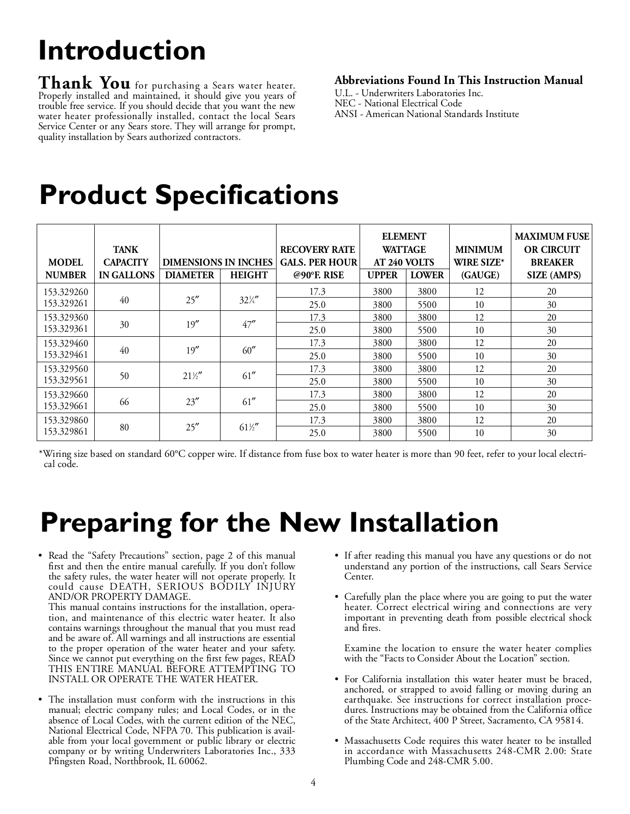
153329260
153329261
153329266
153329363
153329364
2
153329461
3
153329464
2
153329560
3
153329561
3
153329564
2
153329660
3
153329661
3
153329860
3
153329861
3
153330281
153331280
2
153331290
2
153331412
153331412HA
153331420
153331440
153331441
153331442
153331513HA
153331513
153331520
153331542
153331620
153331630
153331640
153331651
153331660
153331661
153331670
153331682
153331690
153332110
153332161
2
153332319
2
153332463
2
153332563
153333316HA
153333345
2
153333346
153333347
153333415HA
2
153333445
2
153333446
2
153333447
153333546
1533311402
Loading...
Loading...
Nothing found
153329261
Owner’s Manual
32 pgs
1.19 Mb
0
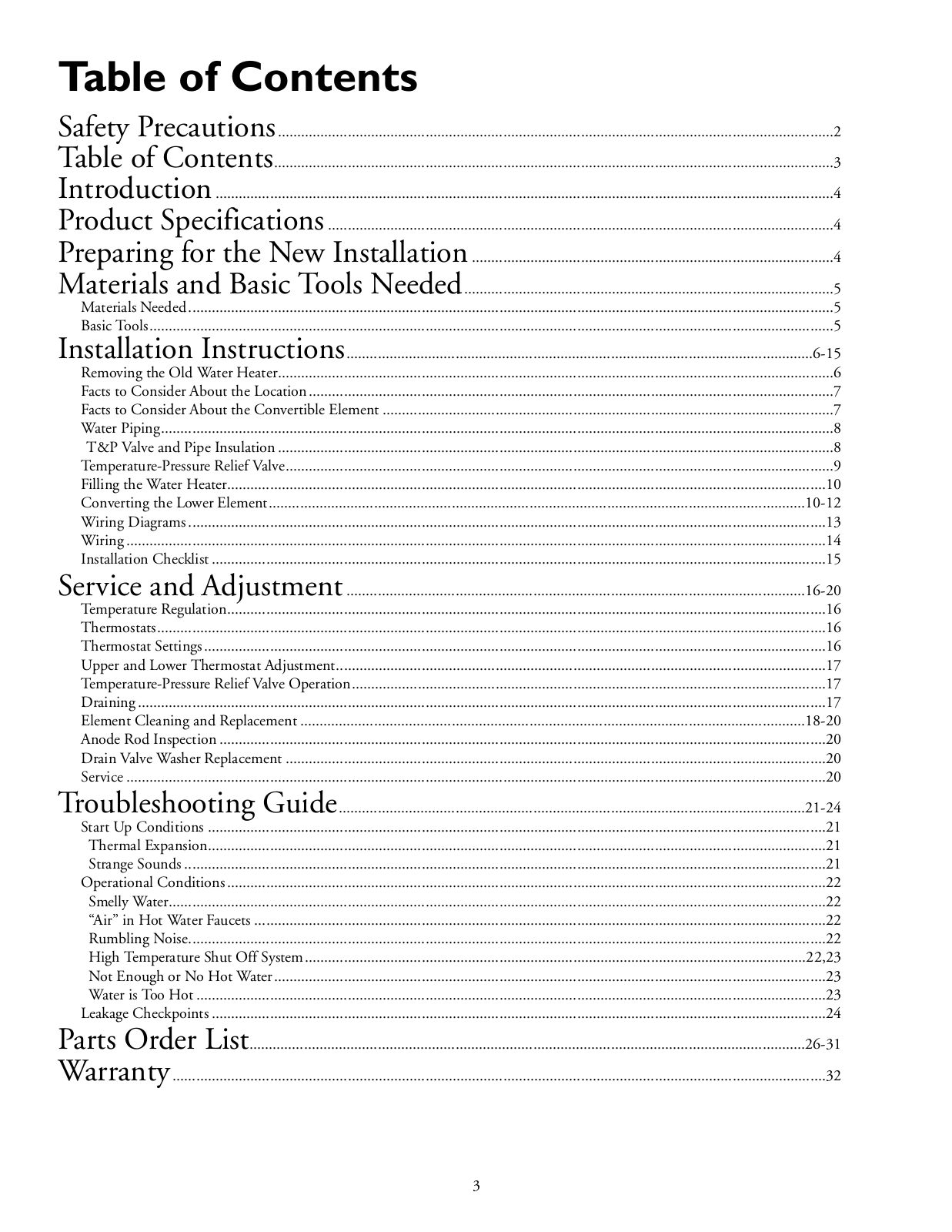
Table of contents
Loading...
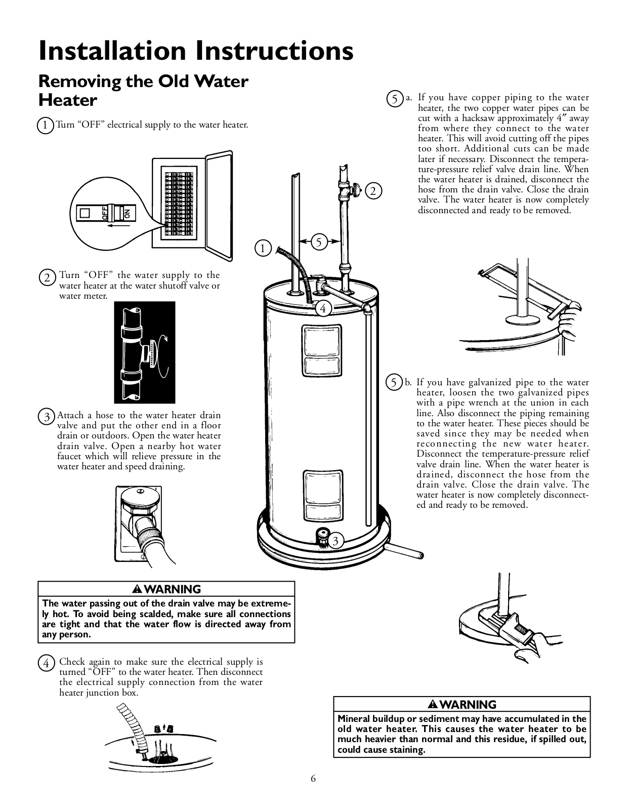
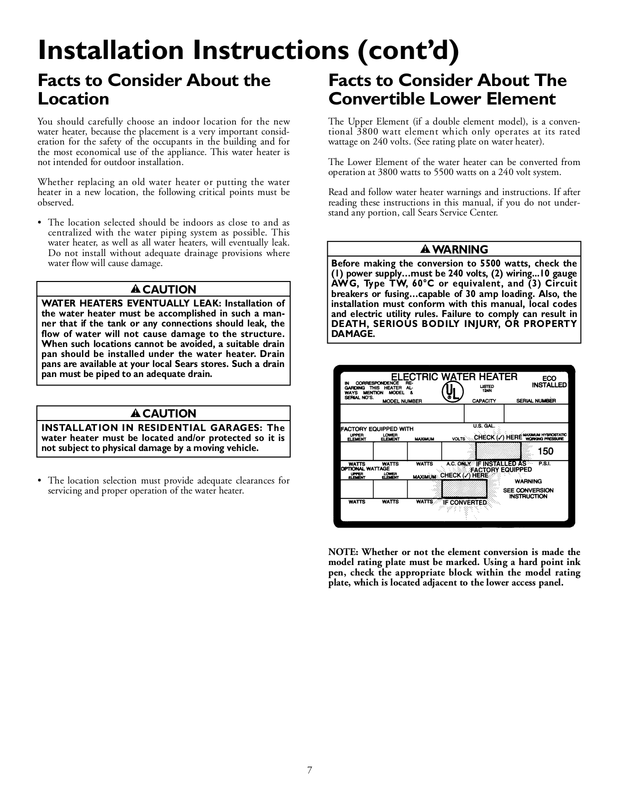
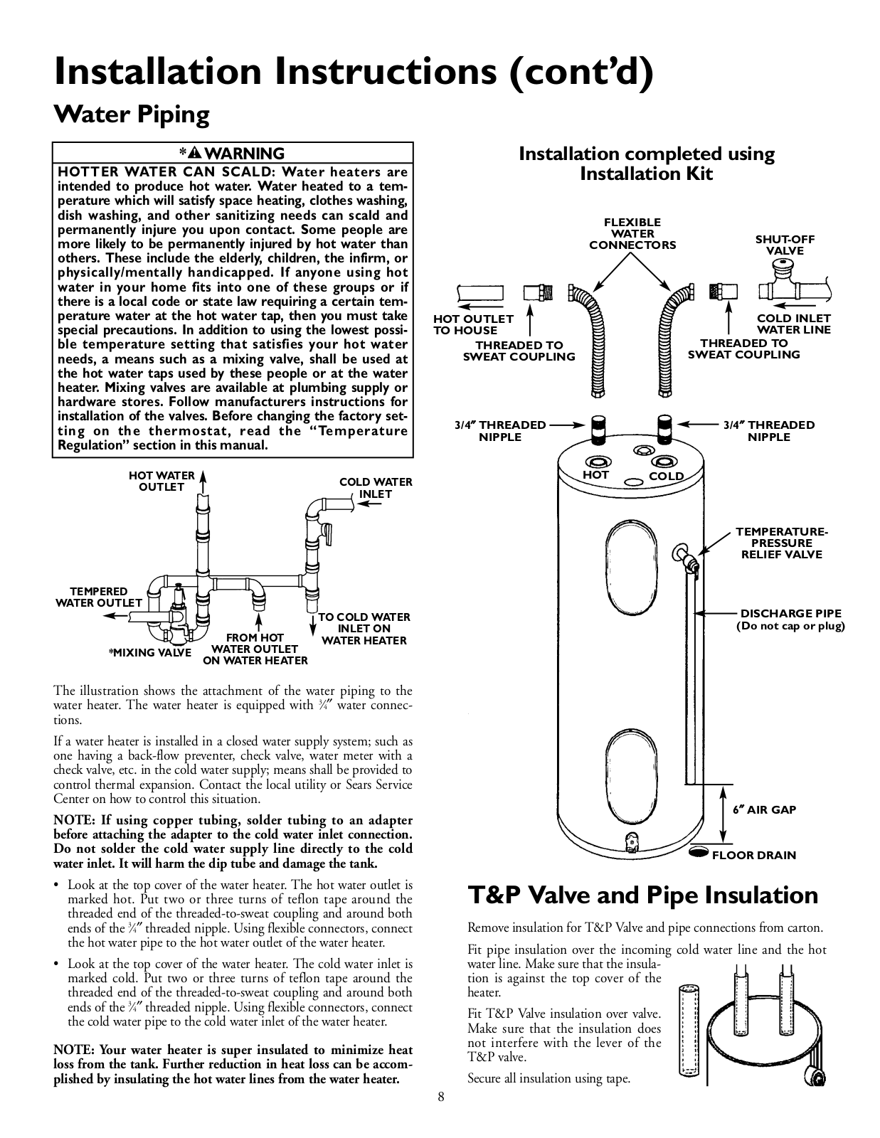
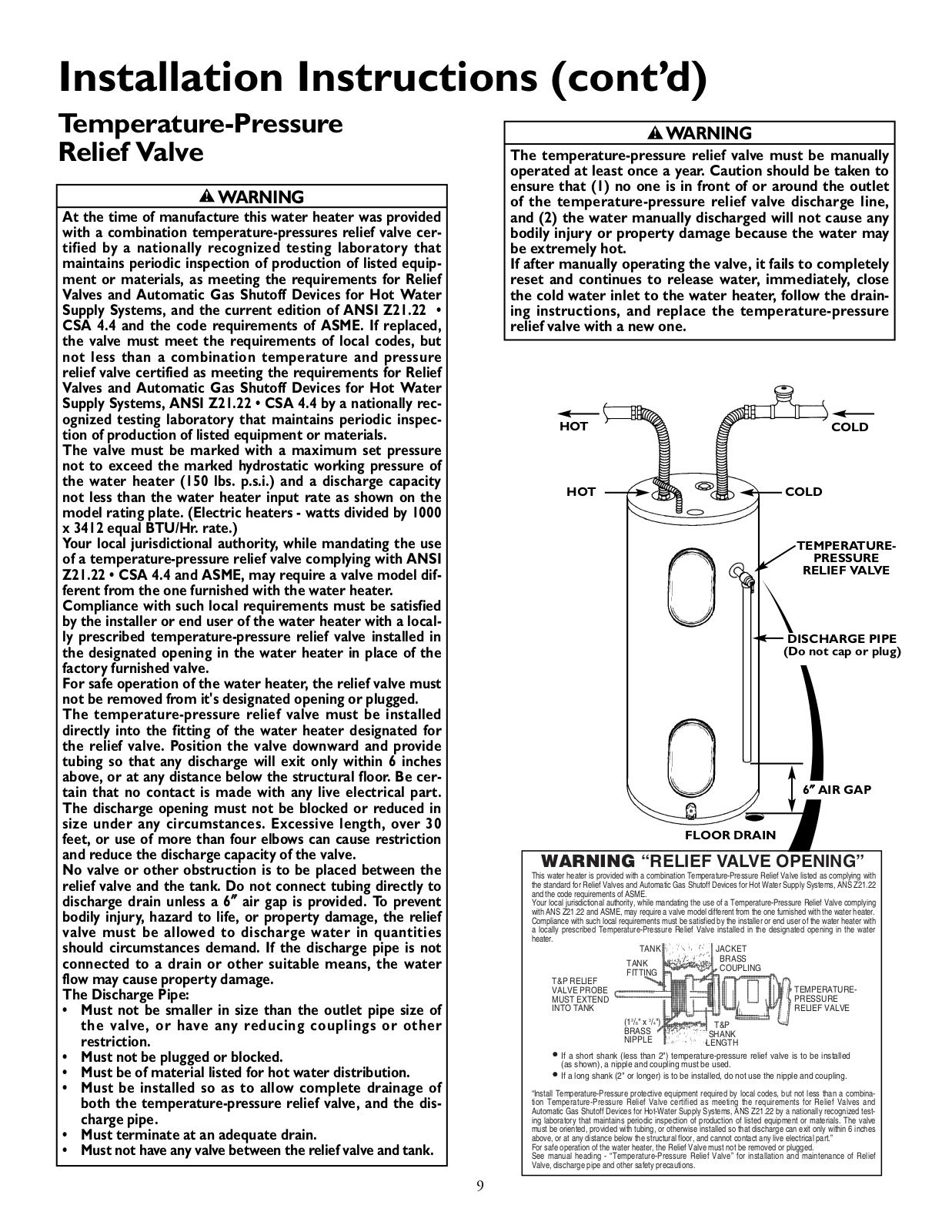
Kenmore 153329261, 153329260 Owner’s Manual
...
Kenmore Owner’s Manual
Download
Specifications and Main Features
Frequently Asked Questions
User Manual
Download
Loading...
+
hidden pages
Unhide
You need points to download manuals.
1 point = 1 manual.
You can buy points or you can get point for every manual you upload.
Buy points
Upload your manuals
 Loading...