

Kenmore 153326863, 153326862, 153326763, 153326762, 153326663 Owner’s Manual
...
Owner’s Manual
O
POWER MISER™ 6
ELECTRIC
WATER HEATER
FOR POTABLE WATER HEATING ONLY.
NOT SUITABLE FOR SPACE HEATING.
MODEL NO.
153.326362 30 Gal.
153.326363 30 Gal.
153.326462 40 Gal.
153.326463 40 Gal.
153.326564 55 Gal.
153.326565 55 Gal.
153.326662 50 Gal. Medium
153.326663 50 Gal. Medium
153.326762 40 Gal. Medium
153.326763 40 Gal. Medium
153.326862 50 Gal. Short
153.326863 50 Gal. Short
LOW LEAD
C
NTENT
Certifi cation applies to all residential electric water heaters with
capacities of 20 to 120 Gallons. Input rating of 12kW or less.
• Safety Instructions
• Installation
• Operation
• Care and Maintenance
• Troubleshooting
• Parts List
SAVE THIS MANUAL FOR FUTURE REFERENCE.
Sears, Roebuck and Co., Hoffman Estates, IL 60179 U.S.A
PRINTED 1112 185796-003
www.sears.com
1
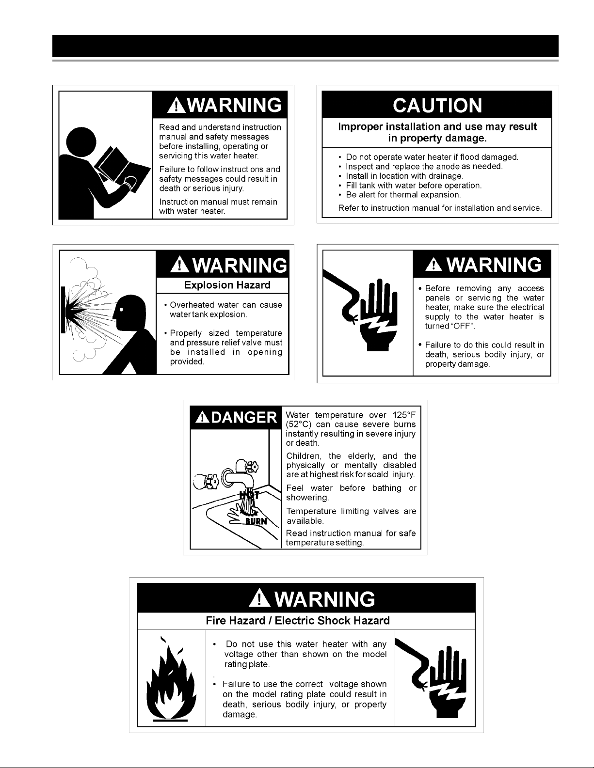
SAFE INSTALLATION, USE AND SERVICE
Your safety and the safety of others is extremely important in the installation, use and servicing of this water heater.
Many safety-related messages and instructions have been provided in this manual and on your own water heater to warn
you and others of a potential injury hazard. Read and obey all safety messages and instructions throughout this manual.
It is very important that the meaning of each safety message is understood by you and others who install, use or service
this water heater.
This is the safety alert symbol. It is used to alert you
to potential personal injury hazards. Obey all safety
messages that follow this symbol to avoid possible
injury or death.
DANGER indicates an imminently hazardous
DANGER
WARNING
situation which, if not avoided, will result in
death or injury.
WARNING indicates a potentially
hazardous situation which, if not avoided,
could result in death or injury.
CAUTION indicates a potentially hazardous
CAUTION
CAUTION
All safety messages will generally tell you about the type of hazard, what can happen if you do not follow the safety message
and how to avoid the risk of injury.
The California Safe Drinking Water and Toxic Enforcement Act requires the Governor of California to publish a list of substances
known to the State of California to cause cancer, birth defects, or other reproductive harm, and requires businesses to warn
of potential exposure to such substances.
WARNING: This product contains a chemical known to the State of California to cause cancer, birth defects, or other
reproductive harm. This appliance can cause low level exposure to some of the substances listed in the act.
situation which, if not avoided, could
result in minor or moderate injury.
CAUTION used without the safety alert
symbol indicates a potentially hazardous
situation which, if not avoided, could
result in property damage.
IMPORTANT DEFINITIONS
• Sears Service Center: The Sears Service Center has the ability equivalent to a licensed tradesman in the fi elds of plumbing and
electrical work including a thorough understanding of the requirements of the National Electrical Code as it relates to the installation
of electric water heaters. The Sears Service Center also has a thorough understanding of this instruction manual, and is able to
perform repairs strictly in accordance with the service guidelines provided by the manufacturer.
© 2012 Sears, Roebuck and Co.
2
GENERAL SAFETY
3

TABLE OF CONTENTS
SAFE INSTALLATION, USE AND SERVICE....................................................................................................................................... 2
GENERAL SAFETY............................................................................................................................................................................. 3
TABLE OF CONTENTS ....................................................................................................................................................................... 4
INTRODUCTION ................................................................................................................................................................................. 5
PRODUCT SPECIFICATIONS ............................................................................................................................................................ 5
MATERIALS AND BASIC TOOLS NEEDED ....................................................................................................................................... 6
Materials Needed .......................................................................................................................................................................... 6
Basic Tools .................................................................................................................................................................................... 6
Additional Tools Needed When Sweat Soldering ......................................................................................................................... 6
INSTALLATION INSTRUCTIONS .................................................................................................................................................. 7-16
Removing the Old Water Heater ................................................................................................................................................ 7,8
Facts to Consider About the Location ........................................................................................................................................... 8
Insulation Blankets ........................................................................................................................................................................ 8
Facts to Consider About the Convertible Lower Element .......................................................................................................... 8,9
Water Piping ............................................................................................................................................................................ 9,10
T & P Valve and Pipe Insulation .................................................................................................................................................. 10
Temperature-Pressure Relief Valve ........................................................................................................................................10,11
Filling the Water Heater .............................................................................................................................................................. 12
Converting the Lower Element .............................................................................................................................................. 12-14
Wiring .................................................................................................................................................................................... 14,15
Wiring Diagrams ......................................................................................................................................................................... 16
SERVICE AND ADJUSTMENT .................................................................................................................................................... 17-22
Temperature Regulation ............................................................................................................................................................. 17
Thermostats ................................................................................................................................................................................ 17
Temperature Settings .................................................................................................................................................................. 17
Upper and Lower Thermostat Adjustments ........................................................................................................................... 17,18
Anode Rod Inspection ................................................................................................................................................................ 18
Temperature-Pressure Relief Valve Operation ........................................................................................................................... 18
Draining and Flushing ............................................................................................................................................................ 18,19
Thermostat Removal/Replacement ............................................................................................................................................ 19
Element Cleaning/Replacement ............................................................................................................................................ 19-22
Drain Valve Washer Replacement .............................................................................................................................................. 22
Service ........................................................................................................................................................................................ 22
TROUBLESHOOTING GUIDE ..................................................................................................................................................... 23-25
Start Up Conditions ................................................................................................................................................................... 23
Thermal Expansion ............................................................................................................................................................. 23
Strange Sounds .................................................................................................................................................................. 23
Operational Conditions .......................................................................................................................................................... 23-25
Smelly Water ................................................................................................................................................................... 23,24
“Air” in Hot Water Faucets .................................................................................................................................................. 24
Rumbling Noise ................................................................................................................................................................... 24
High Temperature Shut Off System ..................................................................................................................................... 24
Not Enough or No Hot Water .......................................................................................................................................... 24,25
Water Is Too Hot .................................................................................................................................................................. 25
Leakage Checkpoints ................................................................................................................................................................. 26
REPAIR PARTS LIST ................................................................................................................................................................... 27-29
NOTES ......................................................................................................................................................................................... 30,31
WARRANTY ...................................................................................................................................................................................... 32
4
INTRODUCTION
Thank You for purchasing a Sears water heater. Properly
installed and maintained, it should give you years of trouble free
service. It is strongly suggested that this new water heater be
professionally installed, contact the local Sears Service Center or
any Sears store. They will arrange for prompt, quality installation
by Sears authorized contractors.
Abbreviations Found In This Instruction Manual:
UL – Underwriters Laboratories Inc.
NEC – National Electrical Code
ANSI – American National Standards Institute
AHRI - Air Conditioning, Heating and Refrigeration Institute
• Read the General Safety section, page 3 of this manual fi rst
and then the entire manual carefully. If you don’t follow the
safety rules, the water heater will not operate properly. It
could cause DEATH, SERIOUS BODILY INJURY AND/OR
PROPERTY DAMAGE.
This manual contains instructions for the installation,
operation, and maintenance of this electric water heater. It
also contains warnings throughout the manual that you must
read and be aware of. All warnings and all instructions are
essential to the proper operation of the water heater and your
safety. Since we cannot put everything on the fi rst few pages,
READ THIS ENTIRE MANUAL BEFORE ATTEMPTING TO
INSTALL OR OPERATE THE WATER HEATER.
• The installation must conform with the instructions in this
manual; electric company rules; and Local Codes, or in
the absence of Local Codes, with the current edition of the
NEC - National Electrical Code, NFPA 70. This publication
is available from your local government or public library or
electric company or by writing Underwriters Laboratories Inc.,
333 Pfi ngsten Road, Northbrook, IL 60062.
• If after reading this manual you have any questions or do not
understand any portion of the instructions, call Sears Service
Center.
• Carefully plan the place where you are going to put the water
heater. Correct electrical wiring and connections are very
important in preventing death from possible electrical shock
and fi res.
Examine the location to ensure the water heater complies with
the Facts to Consider About the Location section.
For California installation, this water heater must be braced,
anchored, or strapped to avoid falling or moving during an
earthquake. See instructions for correct installation procedures.
Instructions may be obtained from California’s Office of
the State Architect, 1102 Q Street, Suite 5100, Sacramento,
CA 95811. Instructions can also be downloaded to your computer
at www.dsa.dgs.ca.gov/Pubs.
Massachusetts Code requires this water heater to be installed
in accordance with Massachusetts 248-CMR 2.00; State
Plumbing Code and 248-CMR 5.00. In the Commonwealth of
Massachusetts, this product must be installed by a licensed
plumber or gasfi tter.
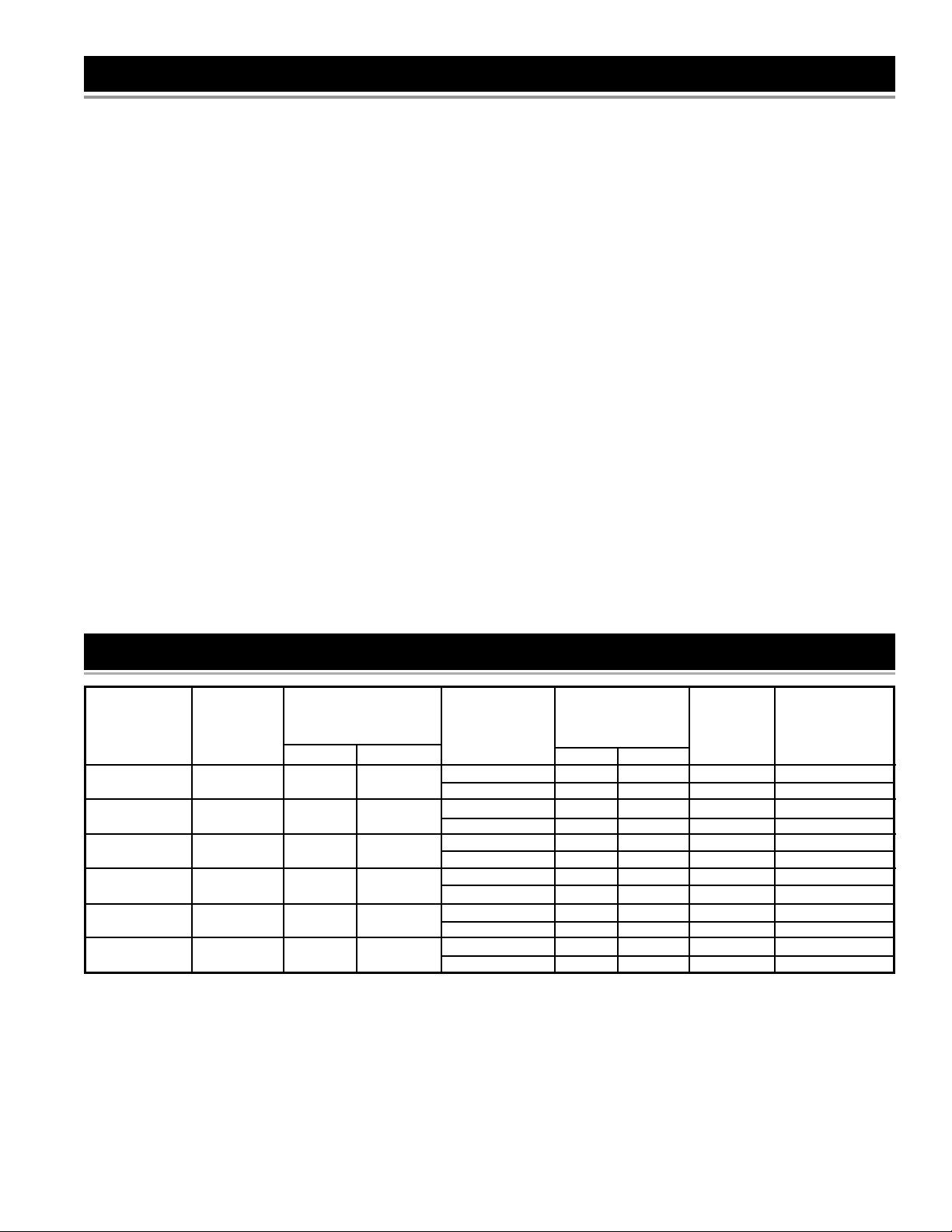
PRODUCT SPECIFICATIONS
MAXIMUM FUSE
RECOVERY RATE MINIMUM OR CIRCUIT
MODEL GALS.PER HOUR WIRE SIZE* BREAKER
NUMBER DIA. HEIGHT @90
153.326362 30 18.0 (457) 46.5 (1181) 17.3 3800 3800 12 20
153.326363 30 18.0 (457) 46.5 (1181) 25.0 3800 5500 10 30
153.326462 40 18.0 (457) 59.5 (1511) 17.3 3800 3800 12 20
153.326463 40 18.0 (457) 59.5 (1511) 25.0 3800 5500 10 30
153.326564 55 20.5 (521) 60.25 (1530) 17.3 3800 3800 12 20
153.326565 55 20.5 (521) 25.0 3800 5500 10 30
153.326662 50 23.0 (584) 49.0 (1245) 17.3 3800 3800 12 20
153.326663 50 23.0 (584) 49.0 (1245) 25.0 3800 5500 10 30
153.326762 40 20.5 (521) 44.0 (1118) 17.3 3800 3800 12 20
153.326763 40 20.5 (521 25.0 3800 5500 10 30
153.326862 47 26.5 (673) 34.0 (864) 17.3 3800 3800 12 20
153.326863 47 26.5 (673) 34.0 (864) 25.0 3800 5500 10 30
* Wiring size based on standard 60°C copper wire. If distance from fuse box to water heater is more than 90 feet, refer to your local
electrical code.
TANK
CAPACITY
IN GALLONS
30 18.0 (457) 46.5 (1181)
40 18.0 (457) 59.5 (1511)
55 20.0 (508) 60.25 (1530)
50 23.0 (584) 49.0 (1245)
40 20.5 (521) 44.0 (1118)
50 26.5 (673) 34.0 (864)
DIMENSIONS
IN INCHES (mm)
0
F Rise UPPER LOWER (GAUGE) SIZE (AMPS)
ELEMENT
WATTAGE
@ 240 VOLTS
5
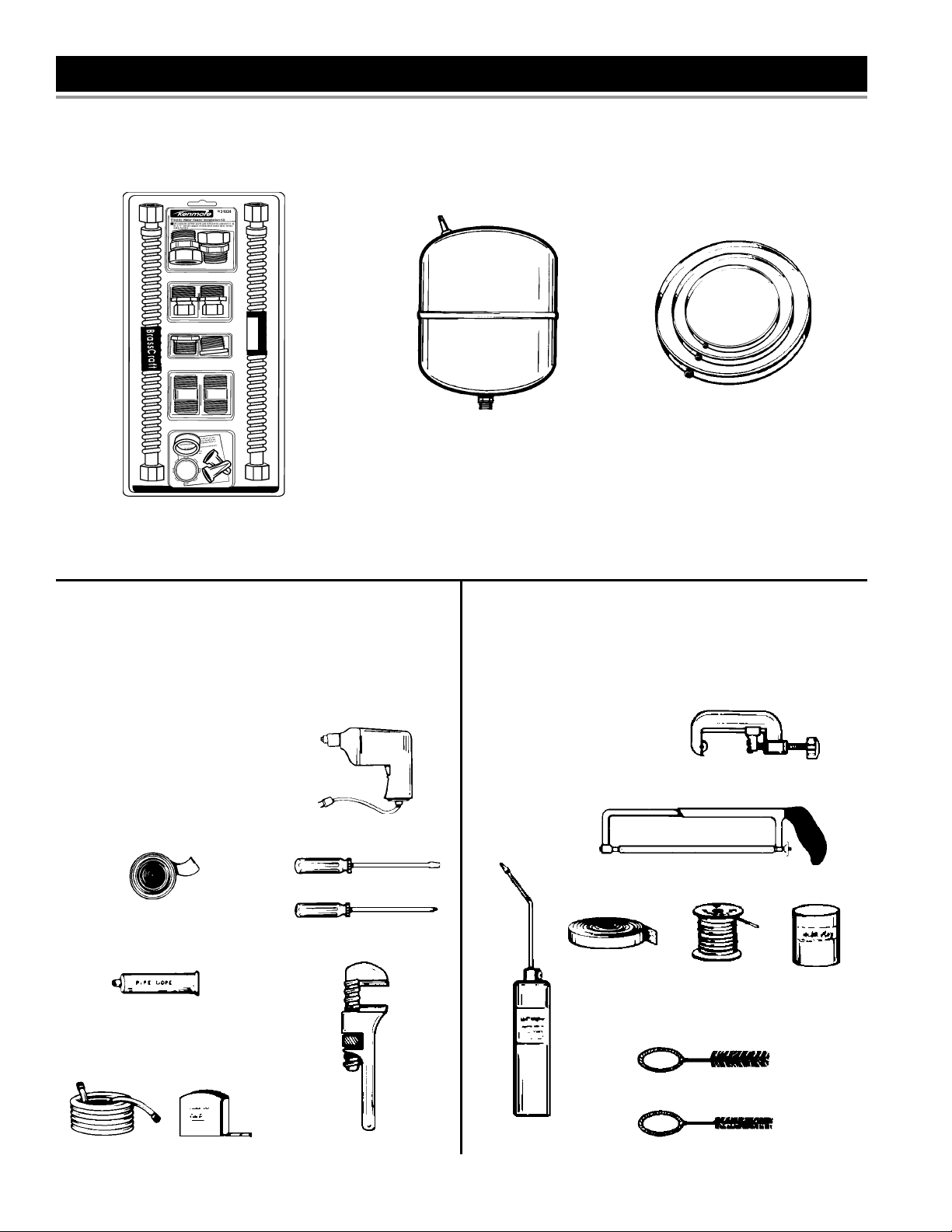
MATERIALS AND BASIC TOOLS NEEDED
Materials Needed
To simplify the installation Sears has available the installation parts shown below. You may or may not need all of these materials,
depending on your type of installation.
EXPANSION TANKS FOR THERMAL
EXPANSION CONDITIONS AVAILABLE IN
2 GALLONS , AND 5 GALLONS CAPACITY
THROUGH LOCAL SEARS STORE OR
SERVICE CENTER.
WATER HEATER INSTALLATION KIT WITH
FLEXIBLE CONNECTORS FOR 3/4” OR 1/2”
THREADED OR COPPER PLUMBING.
Basic Tools
You may or may not need all of these tools, depending on your
type of installation. These tools can be purchased at your local
Sears store.
Pipe Wrench (2)
Screwdriver
6 Foot Tape or Folding Rule
Garden Hose
Drill
Pipe Dope or Tefl on Tape
DRILL
SLOT-HEAD SCREWDRIVER
ROLL OF TEFLON TAPE (USE ON
WATER CONNECTIONS)
PHILLIPS SCREWDRIVER
METAL DRAIN PANS AVAILABLE
IN 20” DIAMETER FOR WATER
HEATERS HAVING A DIAMETER
18” OR LESS, 24” DIAMETER
FOR WATER HEATERS HAVING
A DIAMETER 22” OR LESS AND
AVAILABLE IN 28” DIAMETER
FOR WATER HEATERS HAVING A
DIAMETER 26” OR LESS.
Additional Tools Needed When Sweat
Soldering
Tubing Cutters or Hacksaw
Propane Torch
Soft Solder
Solder Flux
Emery Cloth
Wire Brushes
TUBING CUTTER
HACKSAW
PIPE DOPE (SQUEEZE TUBE)
USE FOR WATER CONNECTIONS
ROLL OF
EMERY CLOTH
3/4” (19 mm) WIRE BRUSH
PIPE WRENCHGARDEN HOSE 6 FOOT TAPE
PROPANE
TORCH
6
1/2” (13 mm) WIRE BRUSH
ROLL OF
LEAD-FREE
SOFT SOLDER
SOLDER
FLUX
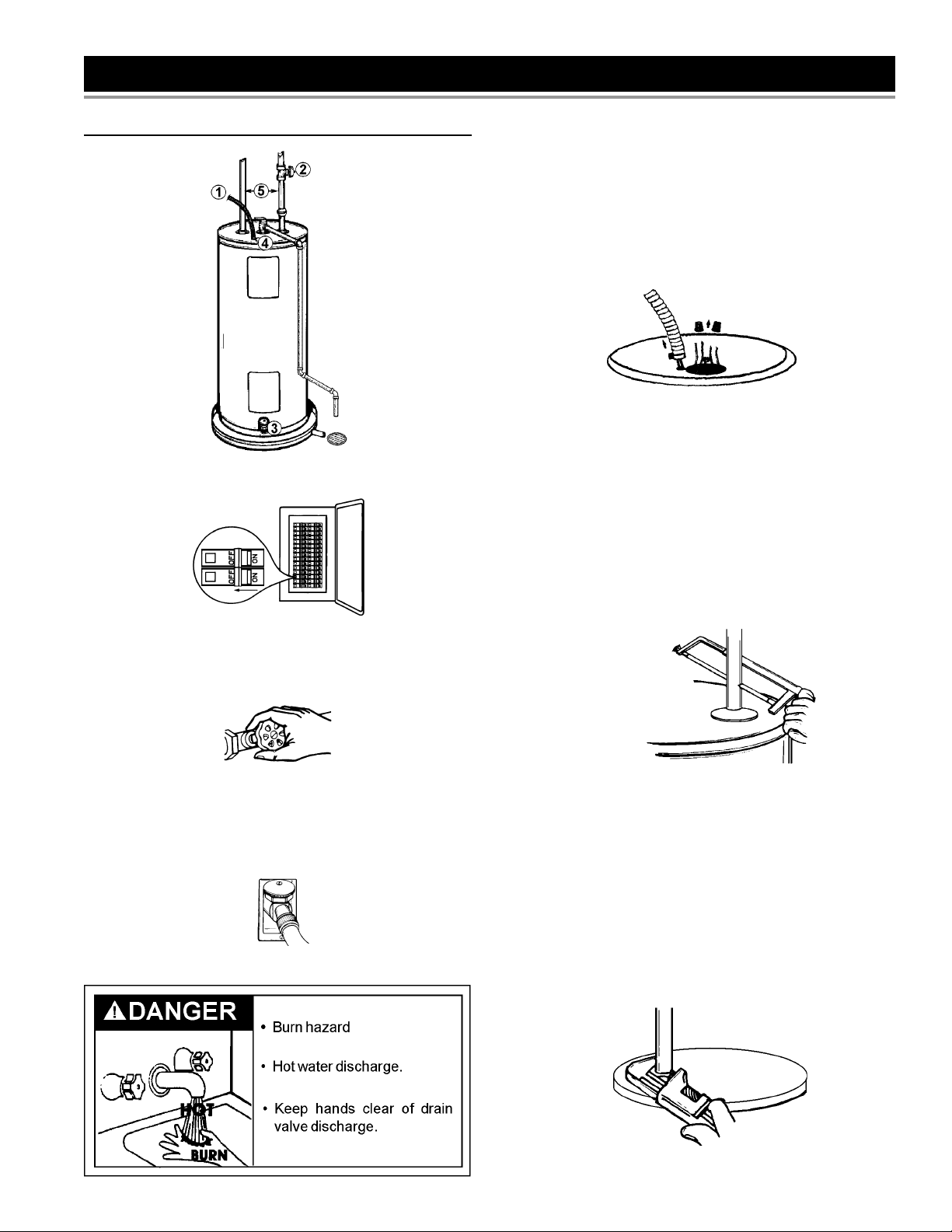
INSTALLATION INSTRUCTIONS
Removing the Old Water Heater
1. Turn “OFF” electrical supply to the water heater.
The water passing out of the drain valve may be extremely hot.
To avoid being scalded, make sure all connections are tight and
that the water fl ow is directed away from any person.
4. Check again to make sure the electrical supply is turned
“OFF” to the water heater. Then unplug the water heater
(cord set) or disconnect the electrical supply connection from
the water heater junction box.
FIGURE 4.
5a. If you have copper piping to the water heater, the two
copper water pipes can be cut with a hacksaw approximately
four inches away from where they connect to the water heater.
This will avoid cutting off the pipes too short. Additional cuts
can be made later if necessary. Disconnect the temperaturepressure relief valve drain line. When the water heater is
drained, disconnect the hose from the drain valve. Close the
drain valve. The water heater is now completely disconnected
and ready to be removed.
FIGURE 1.
2. Open a nearby hot water faucet until the water is no longer hot.
When the water has cooled, turn “OFF” the water supply to the
water heater at the water shut-off valve or water meter.
FIGURE 2.
3. Attach a hose to the water heater drain valve and put the other
end in a fl oor drain or outdoors. Open the water drain valve.
Open a nearby hot water faucet which will relieve pressure
in the water heater and speed draining.
FIGURE 3.
FIGURE 5a.
5b. If you have galvanized pipe to the water heater, loosen the
two galvanized pipes with a pipe wrench at the union in each
line. Also disconnect the piping remaining to the water heater.
These pieces should be saved since they may be needed
when reconnecting the new water heater. Disconnect the
temperature-pressure relief valve drain line. When the water
heater is drained, disconnect the hose from the drain valve.
Close the drain valve. The water heater is now completely
disconnected and ready to be removed.
7
FIGURE 5b.
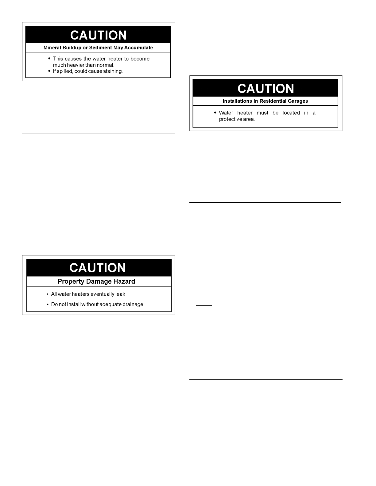
Mineral buildup or sediment may have accumulated in the
old water heater. This causes the water heater to be much
heavier than normal and this residue, if spilled out, could cause
staining.
Facts to Consider About the Location
• Sensors mounted in the metal drain pan that turn off the
water supply to the entire home when water is detected in the
drain pan.
• Water supply shut-off devices that activate based on the water
pressure differential between the cold water and hot water pipes
connected to the water heater.
You should carefully choose an indoor location for the new water
heater, because the placement is a very important consideration
for the safety of the occupants in the building and for the most
economical use of the appliance. This water heater is not
intended for outdoor installation.
Whether replacing an old water heater or putting the water
heater in a new location, the following critical points must be
observed.
• The location selected should be indoors as close to and as
centralized with the water piping system as possible. This
water heater, as well as all water heaters, will eventually leak.
Do not install without adequate drainage provisions so water
fl ow will not cause damage.
WATER HEATERS EVENTUALLY LEAK: Installation of the water
heater must be accomplished in such a manner that if the tank
or any connections should leak, the fl ow of water will not cause
damage to the structure. When such locations cannot be avoided,
a suitable metal drain pan should be installed under the water
heater. Drain pans are available at your local Sears stores. Such
drain pans must be piped to an adequate drain.
Water heater life depends upon water quality, water pressure
and the environment in which the water heater is installed. Water
heaters are sometimes installed in locations where leakage may
result in property damage, even with the use of a metal drain pan
piped to a drain. However, unanticipated damage can be reduced
or prevented by a leak detector or water shut-off device used
in conjunction with a piped metal drain pan. These devices are
available from some plumbing supply wholesalers and retailers,
and detect and react to leakage in various ways:
• Sensors mounted in the metal drain pan that trigger an alarm or turn
off the incoming water to the water heater when leakage is detected.
INSTALLATION IN RESIDENTIAL GARAGES: The water heater
must be located and/or protected so it is not subject to physical
damage by a moving vehicle.
• The location selection must provide adequate clearances for
servicing and proper operation of the water heater.
Insulation Blankets
Insulation blankets are available to the general public for external
use on electric water heaters but are not necessary with this
product. The purpose of an insulation blanket is to reduce
the standby heat loss encountered with storage tank heaters.
Your water heater meets or exceeds the National Appliance
Energy Conversation Act standards with respect to insulation
and standby loss requirements, making an insulation blanket
unnecessary.
Should you choose to apply an insulation blanket to this heater,
you should follow these instructions below. Failure to follow these
instructions can result in fi re, serious personal injury, or death.
• Do not cover the temperature and pressure relief (T & P) valve
with an insulation blanket.
• Do not cover the instruction manual. Keep it on the side of
the water heater or nearby for future reference.
• Do obtain new warning and instruction labels for placement
on the blanket directly over the existing labels.
Facts to Consider About the
Convertible Lower Element
The Upper Element (if a double element model) is a conventional
3800 watt element which only operates at its rated wattage on
240 volts. (See rating plate on the water heater).
The Lower Element of the water heater can be converted from
operation at 3800 watts to 5500 watts on a 240 volt system.
Read and follow water heater warnings and instructions. If after
reading these instructions in this manual, you do not understand
any portion, call Sears Service Center.
8
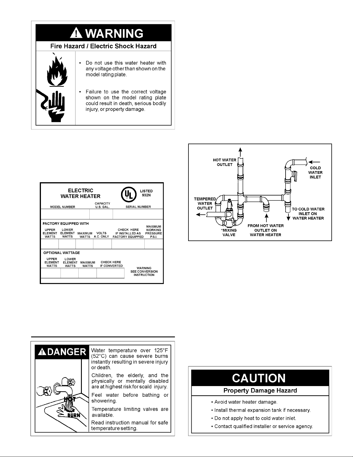
HOTTER WATER CAN SCALD: Water heaters are intended
to produce hot water. Water heated to a temperature which
will satisfy clothes washing, dish washing, and other sanitizing
needs can scald and permanently injure you upon contact. Some
people are more likely to be permanently injured by hot water
than others. These include the elderly, children, the infi rm, or
physically/mentally handicapped. If anyone using hot water in
your home fi ts into one of these groups or if there is a local code
or state law requiring a certain temperature water at the hot water
tap, then you must take special precautions. In addition to using
the lowest possible temperature setting that satisfi es your hot
water needs, a means such as a mixing valve should be used at
the hot water taps used by these people or at the water heater.
Mixing valves are available at plumbing supply or hardware
stores. Follow manufacturers instructions for installation of the
valves. Before changing the factory setting on the thermostat,
read the Temperature Regulation section in this manual.
Before making the conversion to 5500 watts, make sure that the
(1) power supply is 240 volts, (2) the wiring is 10 gauge AWG
@ Type TW, 60°C or equivalent, and (3) the circuit breakers
or fusing are capable of 30 amp loading. Also, the installation
must conform with this manual, local codes and electric utility
rules. Failure to comply can result in DEATH, SERIOUS BODILY
INJURY, OR PROPERTY DAMAGE.
FIGURE 6.
NOTE: Whether or not the element conversion is made the
model rating plate must be marked. Using a hard point ink pen,
check the appropriate block within the model rating plate, which
is located adjacent to the lower access panel.
Water Piping
See Figure 7 (below) for mixing valve usage.
FIGURE 7.
Figure 8 shows the attachment of the water piping to the
water heater. The water heater is equipped with 3/4” water
connections.
If a water heater is installed in a closed water supply system; such
as one having a back-fl ow preventer, check valve, water meter
with a check valve, etc... in the cold water supply; means must
be provided to control thermal expansion. Contact the local utility
or Sears Service Center on how to control this situation.
NOTE: If using copper tubing, solder tubing to an adapter
before attaching the adapter to the water inlet connection.
Do not solder the water supply lines directly to the cold water
inlet. It will harm the dip tube and damage the tank.
9
NOTE: To protect against untimely corrosion of hot and cold
T&P Relief Valve
T&P Relief Valve
Drain Line
Manual Relief Lever
T&P Relief Valve Insulation
water fi ttings, it is strongly recommended that di-electric
unions or couplings be installed on this water heater when
connected to copper pipe.
1. Look at the top cover of the water heater. The hot water outlet
is marked hot. Put two or three turns of tefl on tape around
the threaded end of the threaded-to-sweat coupling and
around both ends of the 3/4” threaded nipple. Using fl exible
connectors, connect the hot water pipe to the hot water outlet
of the water heater.
valve. See Figure 9. Apply gentle pressure to the insulation
to ensure that it is fully seated on the T&P Relief Valve. Once
seated, secure the insulation with duct tape, electrical tape, or
equivalent. IMPORTANT: The insulation and tape must not
block the discharge opening or hinder access to the manual
relief lever (Figure 9). Ensure a discharge pipe is installed
into the T&P valve discharge opening per the instructions in
this manual.
4. Locate the hot water (outlet) & cold water (inlet) pipes to the
water heater.
2. Look at the top cover of the water heater. The cold water inlet
is marked cold. Put two or three turns of tefl on tape around
the threaded end of the threaded-to-sweat coupling and
around both ends of the 3/4” threaded nipple. Using fl exible
connectors, connect the cold water pipe to the cold water inlet
of the water heater.
NOTE: Your water heater is insulated to minimize heat
loss from the tank. Further reduction in heat loss can be
accomplished by insulating the hot water lines from the
water heater.
5. Locate the slit running the length of a section of pipe
insulation.
6. Spread the slit open and slip the insulation over the cold
water (inlet) pipe. Apply gentle pressure along the length of
the insulation to ensure that it is fully seated around the pipe.
Also, ensure that the base of the insulation is fl ush with the
water heater. Once seated, secure the insulation with duct
tape, electrical tape, or equivalent.
7. Repeat steps 5 and 6 for the hot water (outlet) pipe.
8. Add additional sections of pipe insulation as needed.
FIGURE 8.
T & P Valve and Pipe Insulation
1. Locate the temperature and pressure relief valve on the water
heater (also known as a T&P relief valve). See Figure 9.
2. Locate the slit running the length of the T&P relief valve
insulation.
3. Spread the slit open and fi t the insulation over the T&P relief
FIGURE 9.
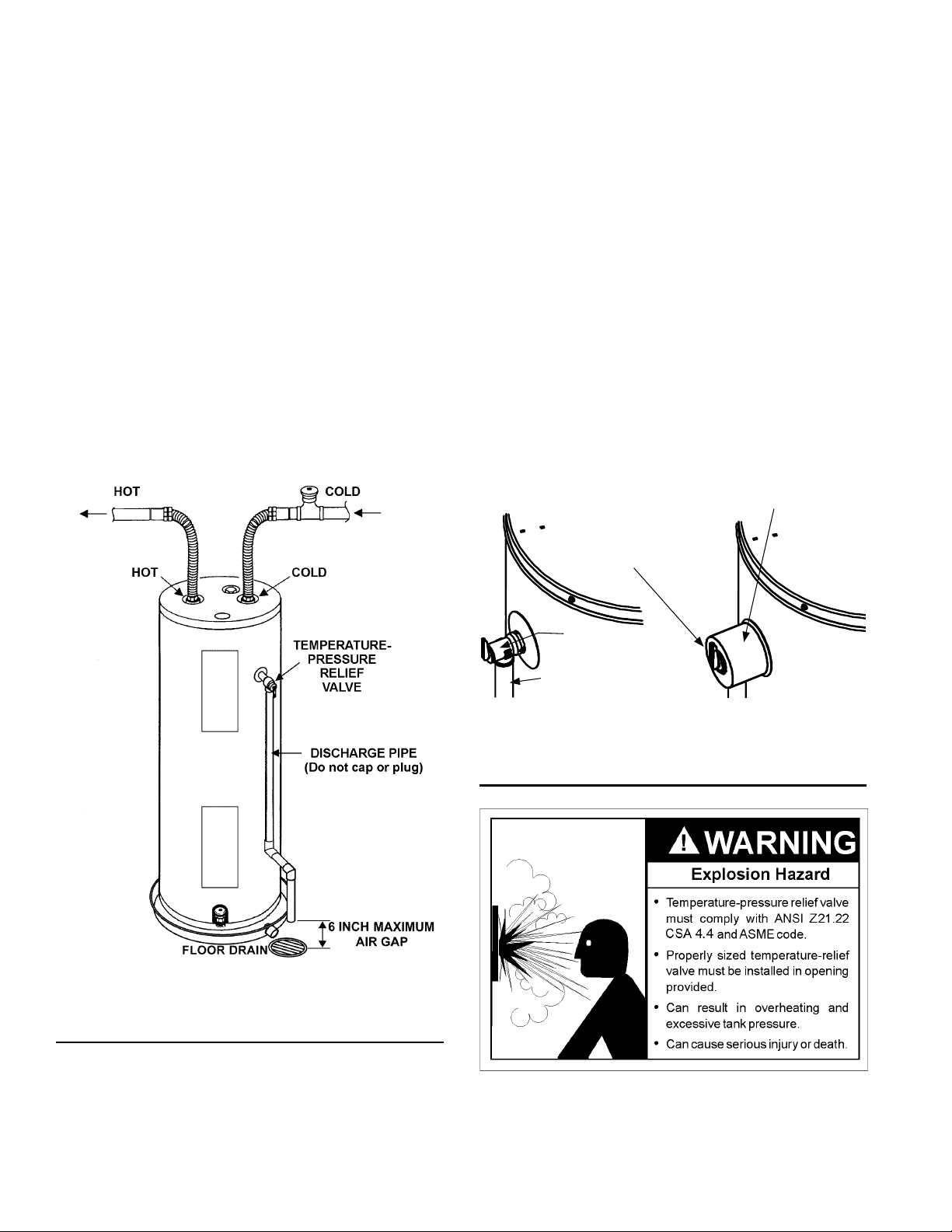
Temperature-Pressure Relief Valve
This heater is provided with a properly certifi ed combination
temperature - pressure relief valve by the manufacturer.
The valve is certifi ed by a nationally recognized testing laboratory
that maintains periodic inspection of production of listed
10
 Loading...