

Owners
Manual
FOR POTABLEWATER
HEATING ONLY
NOT SUITABLEFOR
SPACEHEATING
Model No.
153.321510HT 50 Gal.
153.321511HT 50 Gal.
Caution:
Read and Follow
All Safety Rules and
Operating Instructions
Before First Use of
This Product.
ENDURA
ELECTRIC
WATER HEATER
• Safety Instructions
• Installation
• Operation
• Care and Maintenance
• Troubleshooting
• Parts List
SavethisManual for Future Reference.
Sears, Roebuck and Co., Hoffman Estates, IL 60179 U.S.A.
GAMA certificationapplies to all residential electric water heaters with
capacitiesof 20 to 120Galtons. Input rating of 12 Kw or lessat a voltage
no greaterthan 250
&WARNING
READ THE GENERAL SAFETY SECTION BEGINNING ON INSIDE COVER
AND THEN THIS ENTIRE MANUAL BEFORE INSTALLING OR OPERAT-
ING THIS WATER HEATER.
Safety Precautions
_,WARNING
Improper installation, adjustment, alteration, service or
maintenance can causeDEATH, SERIOUS BODILY INJURY,
OR PROPERTY DAMAGE. Refer to this manual for assis-
tanceor consultyour localSearsServiceCenter for further
information.
_,WARNING
At the time ofmanufacturethiswaterheaterwasprovidedwith
a combinationtemperature-pressuresrelief valvecertlfledby a
nationallyrecognizedtestinglaboratorythat maintainsperiodici
inspectionof productionof listedequipmentor materials, as
meetingthe requirementsfor ReliefValvesand AutomaticGas
ShutoffDevicesfor Hot Water SupplySystems,andthe latest
edition of ANSI Z21.22andthe coderequirementsofASME.If
replaced,the valvemustmeet the requirements of localcodes,
but not lessthan a combinationtemperatureand pressurerelief
valvecertifiedas meeting therequirementsfor ReliefValvesand
AutomaticGasShutoffDevicesfor Hot Water SupplySystems,
ANSI Z21.22 by a nationallyrecognizedtestinglaboratorythat
maintainsperiodic inspectionof productionoflistedequipment
ormaterials.
The valvemust be markedwith a maximum setpressurenot
to exceed the marked hydrostaticworkingpressureof the
water heater (150 Ibsdsq.in.) and a dischargecapacitynot
lessthan the water heaterinput rate as shownonthe model
rating plate.(Electricheaters- watts dividedby 1000x 3415
equalBTU/Hr. rate.)
Yourlocaljurisdictionalauthority,whilemandatingthe useof a
!temperature-pressurerelief valvecomplyingwithANSI Z21.22
andASME,mayrequireavalvemodel differentfromthe onefur-
nishedwiththe waterheater.
Compliancewithsuchlocalrequirements must besatisfiedby
theinstalleror enduserof the water heaterwithalocallypre-
scribedtemperature-pressurerelief valveinstalledinthe desig-
natedopeningin the water heaterin placeof the factoryfur-
nishedvalve.
Forsafeoperationof the water heater,the relief valvemustnot
beremovedfromit'sdesignat..edopeningor plugged.
The temperature-pressurerebelvalvemustbe installeddirecdy
intothe fittingof the waterheaterdesignatedforthe reliefvalve.
Positionthe valvedownwardandprovidetubingsothat anydis-
chargewill exit onlywithin 6 inchesabove,or at any distance
belowthe structuralfloor.Be certainthat nocontact is made
withanyliveelectricalpart. The dischargeopeningmust not be
blockedor reduced in sizeunderany circumstances.Excessive
length,over30feet, or useof morethan four elbowscancause
restrictionandreducethedischargecapacityofthevalve.
No valveorotherobstructionisto be placedbetweenthe relief
valveandthe tank.Do not connecttubingdirectlyto discharge
drainunlessa 6"airgapis provided,Topreventbodilyinlury, haz-
ardto life,or property damage,therelief valvemustheallowed
todischargewater inquantitiesshouldcircumstancesdemand.If
the dischargepipeisnotconnectedto adrainor other suitable
means, the water flow may cause property
damage.
The DischargePipe:
• Mustnotbe smallerin sizethan the outletpipesizeofthe
valve,or haveany reducingcouplingsor other restrictions.
Mustnot be pluggedor blockod.
Mustbeof material listedfor hot water distribution.
Mustbe installedsoasto allowcompletedrainageofboth
the temperature-pressurerelief valve,and the discharge
pipe.
Mustterminateat anadequatedrain.
Mustnot haveanyvalvebetweenthe reliefvalveandtank.
_,WARNING . 1
HAZARD OF ELECTRICAL SHOCK! Before remowngi
any accesspanels or servicing the water heater, make|
sure the e!ectrical supply to the water heater is turned/
"OFF". Fadure to do this could result in DEATH_ SERI-|
OUS BODILY NJURY,OR PROPERTY DAMAGE. |
AWARNING
HOTTER WATER CAN SCALD: Water heaters are
intended to produce hot water. Water heated to a tem-
perature whichwill satisfy spaceheating, clotheswashing,
dish washing, and other saniUzing needs can scald and
permanently injure you upon contact. Some people are
more likelyto be permanently injured by hot water than
others. These includethe elderly,children, the infirm, or I
physicallylmentally handicapped. If anyone using hot
water in your home fits into one of these groups or if
there is a localcode or state law requiring a certain tem-
perature water at the hot water tap, then you must take
specialprecautions. In addition to usingthe lowest possi-
ble temperature setting that satisfies your hot water
needs, a means such as a mixing valve, shall be used at
the hot water taps used by these people or at the water
heater. Mixing valvesare availableat_plumbingsupplyor
hardware stores. Follow manufacturers instr_,ctionsfor
installationof the valves.Before changingthe factory set-
ting on the thermostat, read the "Temperature
Regulation" sectioninthismanual.
.... _, WARNING
WATER HEATERS EQUIPPED FOR ONE VOLTAGE
ONLY: This water heater isequippedfor one type voltage
only.Check the rating plate near the bottom accesspanel
for the correct voltage. DO NOT use this water heater
with any voltage other than the oneshownon the model
rating plate. Failure to usethe correct voltage can cause
problemswhich can result in DEATH, SERIOUS BODILY
INJURY,OR PROPERTY DAMAGE. If you haveany ques-
tionsor doubtsconsultyour electric company.
A,WARNING
INSULATING JACKETS: When installing an external
water heater insulation jacket on an electric water
heater:
a. DO NOT coverthe temperature-pressure relief valve.
b. DO NOT put insulation over the accesscoversor any
access areas.
c. DO NOT cover or remove operating instructmns,and
safety related warning labelsand materials affixed to the
water heater.
_,WARNING
Do not usethis appliance if any part of it hasbeen under
water. An electrical short or malfunctioncouldoccur.The
water heater shouldbe replaced.
_, CAUTION
WATER HEATERS EVENTUALLY LEAK: Installation of
the water heater must be accomplishedin sucha manner
that if the tank or anyconnectionsshouldleak, the flow of
water will not causedamage to the structure. When such
locationscannot be avoided,a suitable drain pan should
be installed under the water heater. Drain pansare avail-
able at your local SearsStore. Such a drain pan must be
piped to an adequate drain. Under no circumstancesis
the manufacturer or Searsto be held liable for any water
damage in connectionwith this water heater.
Table of Contents
Safety Precautions .......................................................................................................................................2
Table
Introduction .............................................................................................................................................................4
Product Specifications ................................................................................................................................4
Preparing for the New Installation ............................................................................................4
Materials and Basic Tools Needed ..........................................................................................5
Materials Needed .................................................................................................................................................................. 5
Basic Tools ............................................................................................................................................................................ 5
T----mstanauonInstructions ..................................................................................................................6-15
Removing the Old Water Heater ........................................................................................................................................... .6
Facts m Consider About the Location .................................................................................................................................. 7
Facts to Consider About the Convertible Lower Element ......................................................................................................... 7
Water Piping ....................................................................................................................................................................... 8
Temperature-Pressure Relief Valve............................................................................................................................................ 9
Filling the Water Heater ....................................................................................................................................................... 10
Converting the Lower Element ....................................................................................................................................... 10-12
Wiring Diagrams ............................................................................................................................................................. 13
Wiring .................................................................................................................................................................................... 14
Installation Checklist .............................................................................................................................................................. 15
ot" Contents ...............................................................................................................................................3
:::::::::::::::::::::::::::::::::::::::::::::::::::::::::::::::::: :::::::::::::::::::::::::::::::::::::::::::::::::::::::::::::::::::::::::::::::::::I.!:21°6
Thermostats ............................................................................................................................................................... 16
Thermostat Settings ......................................................................................................................................................... 16
Upper Thermostat Adjustment ............................................................................................................................................ 16
Lower Thermostat Adjustment .................................................................................................................................... 17
Temperature-Pressure Relief Valve Operation ................................................................................................................... 17
Draining ....................................................................................................................................................................... 17
Element Cleaning and Replacement ............................................................................................................................ 18-20
Drain Valve Washer Replacement ........................................................................................................................................... 20
Service .................................................................................................................................................................................... 20
Thermal Expansion...............................................................................................................................................................21
StrangeSounds.....................................................................................................................................................................21
Operational Conditions .................................................................................................................................................... 22-23
Rumbling Noise. ................................................................................................................................................................... 22
High Temperature Shut OffSystem ................................................................................................................................. 22
Not Enough or No Hot Water .................................................................................................................................. .23
Water is Too Hot .................................................................................................................................................... .23
Indicator Light. ............................................................................................................................................................. .23
Leakage Checkpoints ................................................................................................................................................. .24
Parts
---OrderList................................................................................................................................26-27
Warranty ...................................................................................................................................................................28
Introduction
Thank You for purchasing a Sears water heater.
Properly installed and maintained, it should give you years of
trouble free service. If you should decide that you want the new
water heater professionally installed, contact the local Sears
Service Center or any Sears store. They will arrange for prompt,
quality installation by Sears authorized contractors.
Abbreviations Found In This Instruction Manual
U.L.-Underwriters Laboratories, 333 Pfingsten Rd.,
Northbrook, IL 60062
National Electrical Code-This publication is available from your
local government or public library or electric company or by
writing to U.L. above.
A.N.S.I.-American National Standards Institute
Product Specifications
ELEMENT
TANK
MODEL
NUMBER
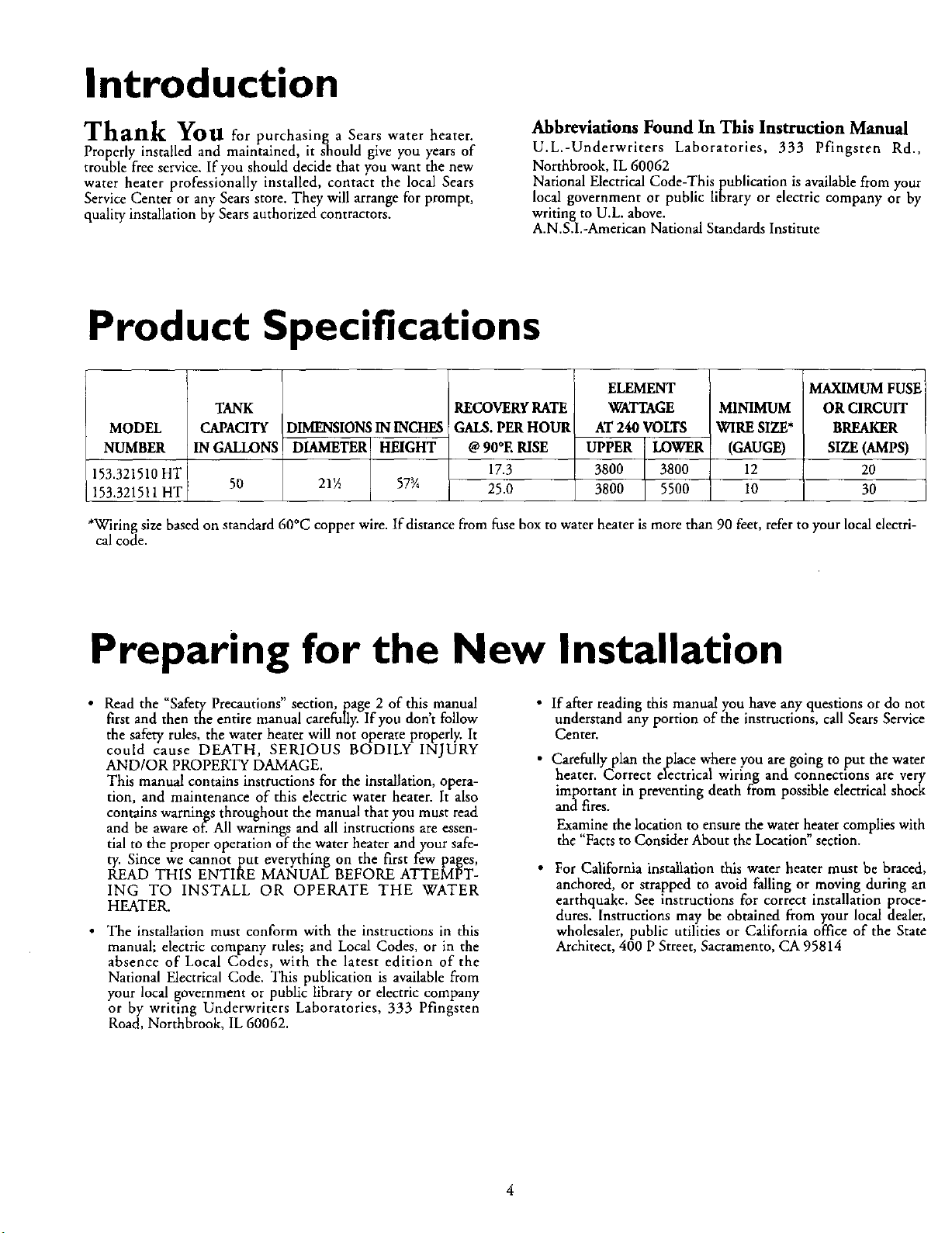
153.321510HT
153.321511HT
*Wiring size based on standard 60°C copper wire. If distance from fuse box to water heater is more than 90 feet, refer to your local electri-
cal code.
CAPACITY
IN GALLONS
50
DIMENSIONSIN INCHES
DIAMETER HEIGHT
21½ 57_A
RECOVERYRATE
GALS.PERHOUR
@90°E RISE
17.3
25.0
WATTAGE MINIMUM
AT 240 VOLTS WIRE SIZE*
UPPER LOWER (GAUGE)
3800 3800 12
3800 5500 ] 10
I
MAXIMUM FUSE
OR CIRCUIT
BREAKER
SIZE (AMPS)
20
30
Preparing for the New Installation
• Read the "Safety Precautions" section, page 2 of this,manual
first and then the entire manual carefully. If you dont follow
the safety rules, the water heater will not operate properly. It
could cause DEATH, SERIOUS BODILY INJURY
AND/OR PROPERTY DAMAGE.
This manual contains instructions for the installation, opera-
tion, and maintenance of this electric water heater. It also
contains warnings throughout the manual that you must read
and be aware of. All warnings and all instructions are essen-
tial to the proper operation of the water heater and your safe-
ty. Since we cannot put everything on the first few pages,
READ THIS ENTIRE MANUAL BEFORE ATTEMPT-
ING TO INSTALL OR OPERATE THE WATER
HEATER.
• The installation must conform with the instructions in this
manual; electric company rules; and Local Codes, or in the
absence of Local Codes, with the latest edition of the
National Electrical Code. This publication is available from
your local government or public library or electric company
or by writing Underwriters Laboratories, 333 Pfingsten
Road, Northbrook, IL 60062.
• Ifafrer reading this manual you have any questions or do not
understand any portion of the instructions, call Sears Service
Center.
• Carefully plan theplace where you are going to put the water
heater. Correct electrical wiring and connections are very
important in preventing death from possible electrical shock
and fires.
Examine the location to ensure the water heater complies with
the "Facts to Consider About the Location" section.
• For California installation this water heater must be braced,
anchored, or strapped to avoid falling or moving during an
earthquake. See instructions for correct installation proce-
dures. Instructions may be obtained from your local dealer,
wholesaler, public utilities or California office of the State
Architect, 400 P Street, Sacramento, CA 95814
Materials and Basic Tools Needed
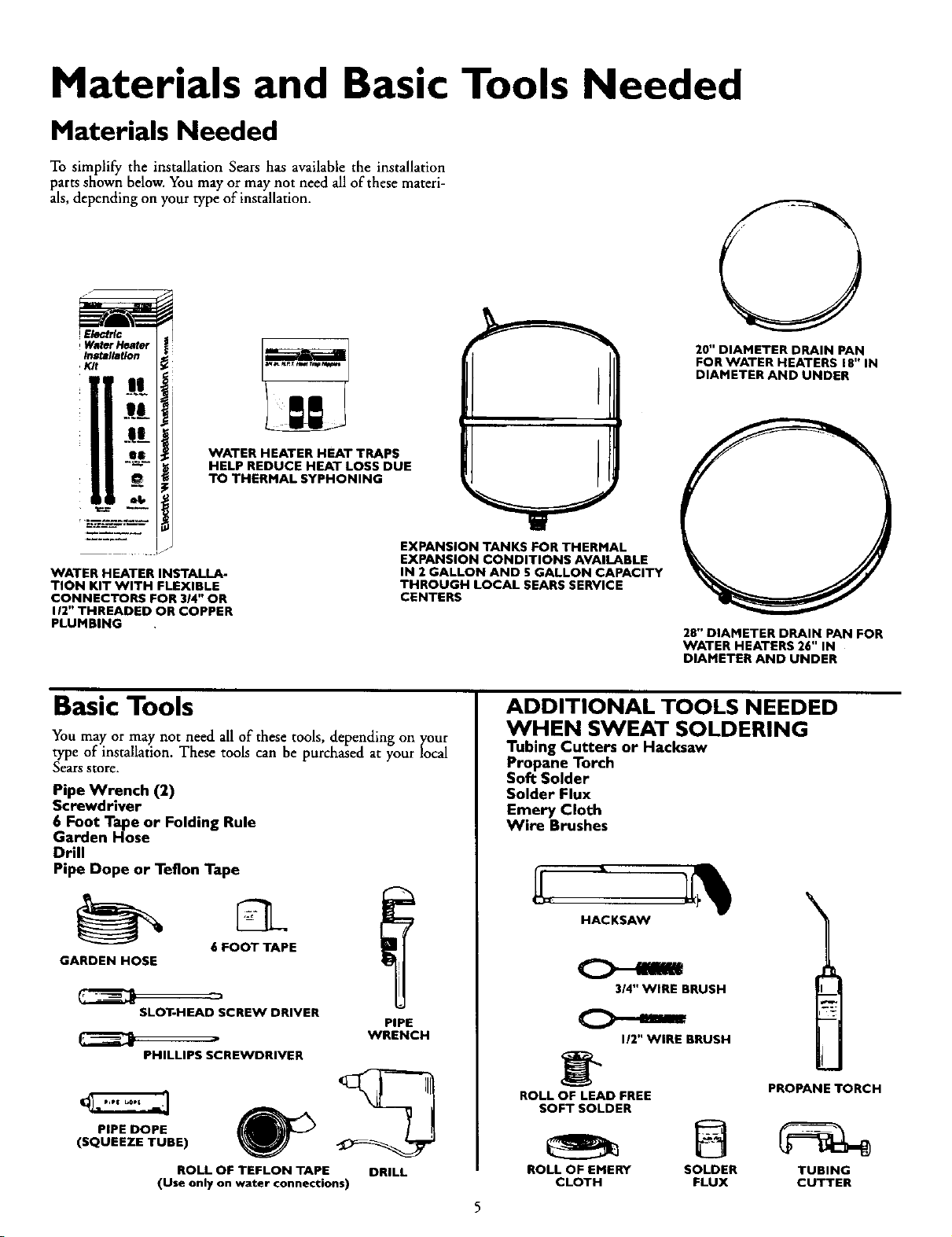
Materials Needed
To simplify the installation Sears has available the installation
parts shown below. You may or may not need all of these materi-
als, depending on your type of installation.
20" DIAMETER DRAIN PAN
FOR WATER HEATERS 18" IN
DIAMETER AND UNDER
11:".
iF
II:',.ti
WATER HEATER HEAT TRAPS
HELP REDUCE HEAT LOSS DUE
TO THERMAL SYPHONING
EXPANSION TANKS FOR THERMAL
EXPANSION CONDITIONS AVAILABLE
WATER HEATER INSTALLA-
TION KIT WITH FLEXIBLE
CONNECTORS FOR 3/4" OR
I/2" THREADED OR COPPER
PLUMBING
IN 2 GALLON AND 5 GALLON CAPACITY
THROUGH LOCAL SEARS SERVICE
CENTERS
Basic Tools
You may or may not need all of these tools, depending on your
type of installation. These tools can be purchased at your local
Sears store.
Pipe Wrench (2)
Screwdriver
6 Foot Tape or Folding Rule
Garden Hose
Drill
Pipe Dope or Teflon Tape
GARDEN HOSE
SLOT-HEAD SCREW DRIVER
PHILLIPS SCREWDRIVER
PIPE DOPE
(SQUEEZE TUBE)
(Use only on water connections)
6 FOOT TAPE
ROLL OF TEFLON TAPE
PIPE
WRENCH
DRILL
28" DIAMETER DRAIN PAN FOR
WATER HEATERS 26" IN
DIAMETER AND UNDER
ADDITIONAL TOOLS NEEDED
WHEN SWEAT SOLDERING
Tubing Cutters or Hacksaw
Propane Torch
Soft Solder
Solder Flux
Emery Cloth
Wire Brushes
HACKSAW
314" WIRE BRUSH
I/2" WIRE BRUSH
_" PROPANE TORCH
ROLL OF LEAD FREE
SOFT SOLDER
ROLL OF EMERY SOLDER TUBING
CLOTH FLUX CUTTER
Installation Instructions
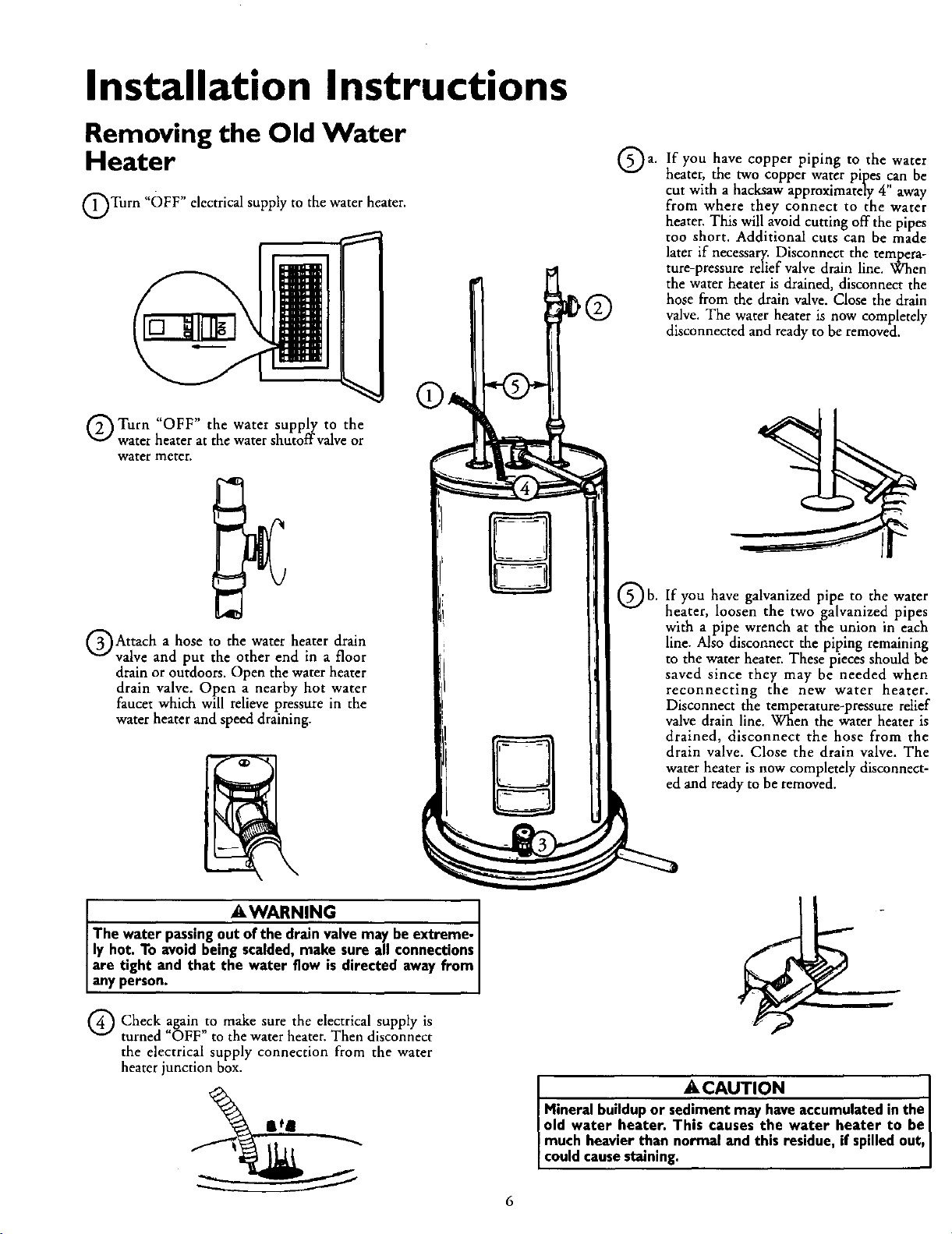
Removing the Old Water
Heater
QTurn "OFF" electricalsupply to the water heater.
Q Turn "OFF" the water supply to the
water heater at the water shutoffvalve or
water meter.
If you have copper piping to the water
a.
heater, the two copper water pipes ,canbe
cut with a hacksaw approximately 4 away
from where they connect to the water
heater. This will avoid cutting off the pipes
too short. Additional cuts can be made
later if necessary. Disconnect the tempera-
ture-pressure relief valve drain line. When
the water heater is drained, disconnect the
hose from the drain valve. Close the drain
valve. The water heater is now completely
disconnected and readyto be removed.
QAttach a hose to the water heater drain
valve and put the other end in a floor
drain or outdoors. Open the water heater
drain valve. Open a nearby hot water
faucet which will relieve pressure in the
water heater and speed draining.
AWARNING I
The water passingout of the drain valvemay beextreme- I
ly hot. To avoidbeing scalded, make sure all connections
are tight and that the water flow ,s directed away from
anyperson.
Q Check to make the electrical supply isagain
turned OFF" to the water heater. Then disconnect
the electrical supply connection from the water
heater junction box.
sure
Qb.
If you have galvanized pipe to the water
heater, loosen the twogalvanized pipes
with a pipe wrench at the union in each
line. Also disconnect the piping remaining
to the water heater. These pieces should be
saved since they may be needed when
reconnecting the new water heater.
Disconnect the temperature-pressure relief
valve drain line. When the water heater is
drained, disconnect the hose from the
drain valve. Close the drain valve. The
water heater is now completely disconnect-
ed and ready to be removed.
• .A.CAUTION
Mineral buildup or sediment may have accumulatedin the
old water heater. This causes the water heater to be I
much heavier than normal and this residue, if spilled out,
coud causestain ng.
6
Installation Instructions (cont'd)
Facts to Consider About the Facts to Consider About The
Location Convertible Lower Element
You should carefully choose an indoor location for the new
water heater, because the placement is a very important consid-
eration for the safety of the occupants in the building and for
the most economical use of the appliance. This water heater is
not intended for outdoor installation.
Whether replacing an old water heater or putting the water
heater in a new location, the following critical points must be
observed.
• The location selected should be indoors as close to and as
centralized with the water piping system as possible. This
water heater, as well as all water heaters, will eventually leak.
Do not install without adequate drainage provisions where
water flow will cause damage.
_,CAUTION
WATER HEATERS EVENTUALLY LEAK: Installation of
the water heater must beaccomplishedin sucha manner
that if the tank or any connectionsshouldleak, the flow of
water will not causedamageto the structure. When such
locationscannot be avoided, a suitable drain pan should
be installed under the water heater. Drain pansare avail-
able at your local Sears stores. Sucha drain pan must be
piped to an adequate drain. Under no circumstances is
the manufacturer or Searsto be held liablefor anywater
damage in connectionwith thiswater heater.
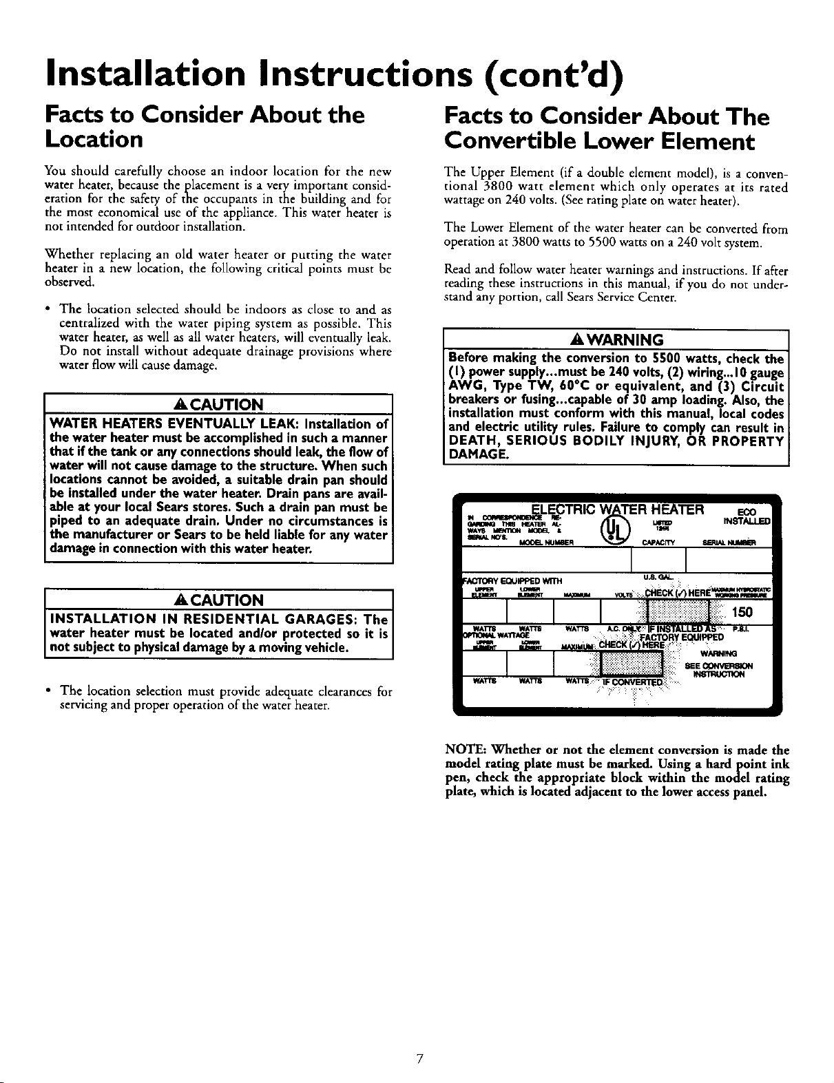
The Upper Element (if a double element model), is a conven-
tional 3800 watt element which only operates at its rated
wattage on 240 volts. (See rating plate on water heater).
The Lower Element of the water heater can be converted from
operation at 3800 watts to 5500 watts on a 24O volt system.
Read and follow water heater warnings and instructions. If after
reading these instructions in this manual, if you do not under-
stand any portion, call Sears Service Center.
_,WARNING
Before making the conversionto 5500 watts, check the
(I) power supply...must be 240volts,(2) wiring...10gauge
AWG, Type TW, 60oc or equivalent, and (3) Circuit
breakers or fusing...capableof 30 amp loading.Also,the
installation must conform with this manual, local codes
and electric utility rules. Failure to comply can result in
DEATH, SERIOUS BODILY INJURY, OR PROPERTY
DAMAGE.
ACAUTION J
INSTALLATION IN RESIDENTIAL GARAGES: The J
water heater must be located and/or protected so it is
not subjectto physicaldamage by a moving vehc e.
• The location selection must provide adequate clearances for
servicing and proper operation of the water heater.
NOTE: Whether or not the element conversion is made the
model rating plate must be marked. Using a hardpoint ink
pen, check the appropriate block within the model rating
plate, which is located adjacent to the lower access panel.
Installation Instructions (cont'd)
Water Piping
&WARNING
HOTTER WATER CAN SCALD: Water heaters are
intended to produce hot water. Water heated to a tem-
perature which will satisfyspaceheating,clothes washing,
dish washing, and other sanitizing needs can scald and
permanently injure you upon contact. Some people are
more likelyto be permanently injured by hot water than
others. These include the elderly, children, the infirm, or
physically/mentally handicapped. If anyone using hot
water in your home fits into one of these groups or if
there is a local code or state law requiring a certain tem-
Jerature water at the hot water tap, then you must take
specialprecautions. In addition to usingthe lowest possi-
ble temperature setting that satisfies your hot water
needs, a means such as a mixing valve, shall be used at
the hot water taps used by these people or at the water ;
heater. Mixing valvesare availableat plumbing supplyor
hardware stores. Follow manufacturers instructions for
installationof the valves.Before changingthe factory set-
ting on the thermostat, read the "Temperature
Regulation"section in this manual.
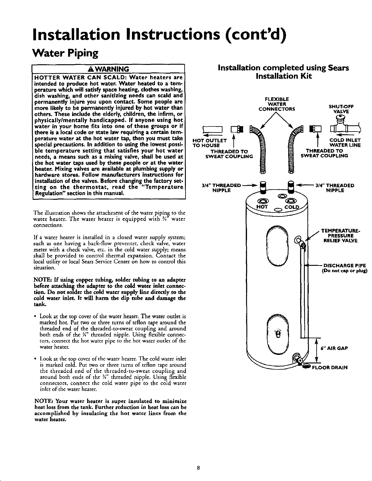
The illustration shows the attachment of the water plpin_ to the
water heater. The water heater is equipped with ¾ water
connections.
If a water heater is installed in a closed water supply system;
such as one having a back-flow preventer, check valve, water
meter with a check valve, etc. in the cold water supply; means
shall be provided to control thermal expansion. Contact the
local utility or local Sears Service Center on how to control this
situation.
NOTE: If using copper tubing, solder tubing to an adapter
before attaching the adapter to the cold water inlet connec-
tion. Do not solder the cold water supply fine directly to the
cold water inlet. It will harm the dip tube and damage the
tanl_
HOT OUTLET
--t
TO HOUSE
THREADED TO
SWEAT COUPLING
Installation completed using Sears
Installation Kit
FLEXIBLE
WATER SHUT-OFF
CONNECTORS VALVE
COLD INLET
WATER LINE
THREADED TO
SWEAT COUPLING
TEMPERATURE-
PRESSURE
RELIEF VALVE
(Do not cap or plug)
• Look at the top cover of the water heater. The water outlet is
marked hot. Put two or three turns of teflon tape around the
threaded end of the threaded-to-sweat coupling and around
both ends of the 3A"threaded nipple. Using flexible connec-
tors, connect the hot water pipe to the hot water outlet of the
water heater.
• Look at the top cover of the water heater. The cold water inlet
is marked cold. Put two or three turns of teflon tape around
the threaded end of the threaded-to-sweat coupling and
around both ends of the _" threaded nipple. Using flexible
connectors, connect the cold water pipe to the cold water
inlet of the water heater.
NOTE: Your water heater is super insulated to minimize
heat loss from the tank. Further reduction in heat loss can be
accomplished by insulating the hot water lines from the
water heater.
FLOOR DRAIN
Installation Instructions (cont'd)
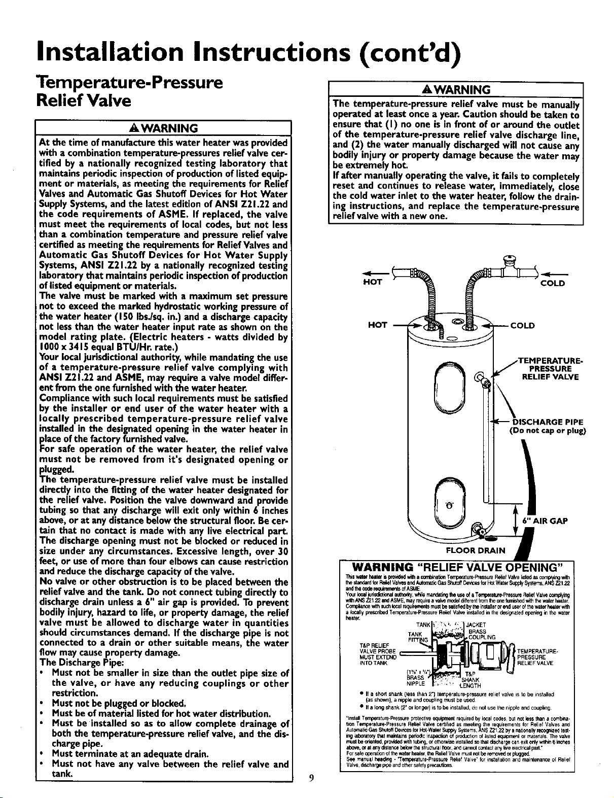
Temperature-Pressure
Relief Valve
,&WARNING
At the time of manufacturethis water heater wasprovided
with a combinationtemperature-pressuresrelief valvecer-
tified by a nationally recognized testing laboratory that
maintains periodic inspectionof productionoflistedequip-
ment or materials, as meeting the requirements for Relief
Valvesand Automatic Gas Shutoff Devicesfor Hot Water
SupplySystems,andthe latest edition of ANSI Z21.22 and
the code requirements of ASME. If replaced, the valve
must meet the requirements of local codes,but not less
than a combination temperature and pressurerelief valve
certified as meeting the requirements for ReliefValvesand
Automatic Gas Shutoff Devices for Hot Water Supply
Systems,ANSI Z21.22 by a nationally recognized testing
laboratory that maintainsperiodicinspectionof production
oflistedequipmentor materials.
The valve must be marked with a maximum set pressure
not to exceed the marked hydrostaticworking pressureof
the water heater (150 Ibs./sq.in.) and a dischargecapacity
not lessthan the water heater input rate as shownon the
model rating plate. (Electric heaters - watts divided by
1000x 3415equal BTU/Hr. rate.)
Yourlocaljurisdictionalauthority, while mandatingthe use
of a temperature-pressure relief valve complying with
ANSI 721.22 and ASME, may require a valve model differ-
ent from the onefurnishedwith the water heater.
Compliancewith suchlocal requirements must be satisfied
_y the installer or end user of the water heater with a
ocally prescribed temperature-pressure relief valve
nstalled in the designatedopeningin the water heater in
placeof thefactory furnishedvalve.
For safe operation of the water heater, the relief valve
must not be removed from it's designated opening or
plugged.
The temperature-pressure relief valve must be installed
directly into the fitting of the water heater designatedfor
the relief valve. Positionthe valve downward and provide
tubing so that any dischargewill exit only within 6 inches
above, or at anydistancebelowthe structuralfloor.Be cer-
tain that no contact is made with any live electrical part.
The dischargeopeningmust not be blockedor reduced in
size under any circumstances. Excessivelength, over 30
feet, or useof more than four elbowscancauserestriction
and reduce the dischargecapacityofthe valve.
No valveor other obstructionisto be placed between the
relief valve and the tank. Do not connect tubingdirectlyto
dischargedrain unlessa 6" air gap is provided.To prevent
bodilyinjury, hazard to life, or property damage,the relief
valve must be allowed to discharge water in quantities
shouldcircumstancesdemand. If the dischargepipe is not
connected to a drain or other suitable means, the water
flow may causeproperty damage.
The DischargePipe:
Must not be smaller in size than the outlet pipe size of
the valve, or have any reducing couplings or other
restriction.
Must not be pluggedor blocked.
Must beofmaterial listed for hot water distribution.
Must be installed so as to allow complete drainage of
both the temperature-pressure relief valve, and the dis-
chargepipe.
Mustterminate at anadequate drain.
Must not have any valve between the relief valve and
tank.
,&WARNING
The temperature-pressure relief valve must be manually
operated at least oncea year. Caution shouldbe taken to
ensure that (I) no one is infront of or around the outlet
of the temperature-pressure relief valve discharge line,
and (2) the water manually dischargedwill not causeany
bodily injury or property damage becausethe water may
be extremely hot.
If after manuallyoperating the valve,it failsto completely
reset and continues to release water, immediately, close
the cold water inlet to the water heater,follow the drain-
ing instructions, and replace the temperature-pressure
relief valve with anew one.
HOT
HOT
RELIEF VALVE
(Do not cap or plug)
6" AIR GAP
WARNING "RELIEF VALVE OPENING"
_,,s witet heaterb provldedwi'hacombinaUonTemperature-PP",=_suteP_ief Valvellstedasascomp,y_ _th
thestandardiorP,_f ValvesandA_omalicGasShtoff_ncestarP,_WaterSupply$yste'_s,AN__122
andthe codereq_JremerdsofASME
Y_r local rf_ional author_,v_le ritar_b'lg theuseo__Temperate-PressureRelielVa_ complying
*ith,_S ;_ 22andA_E, mayrngu_a,_ moderdifterer_Iromthec,_e_Jr_ed _ _ w_r _r
C0mptancevAthsuchlocaln_u_ementsmustbe satsSedbytheinstalerorend_ ofthewat_ healerwith
a locally p,escril_dTemberatute-Pre_uteRefel Val_ instaJledinthedesig_ted openingin1bewalei
TANK BRASS
T&P RELIEF
VALVE PROBE _TEMPERATURE-
INTO TANK I RELIEF VALVE
BRASS _ SHANK
NIPPLE LENGTH
• I1 a shorl stlank (_essthan2") temperature-pressurerelief valve isto be installed
(as shown),a nipple and couplingmust beused
• If a long shank;(2' or longer)is to be installed, donot useIhe nippleand coupling
=InstallTemperature-Pressesprate:tireequipt_nt requiredby k:,cal cedes bulnot lessthan a coml_na-
lion Tempetalure-PresseraReliefValve certifiedas meeting the requirementsforRelief Valvesand
AutoreaticGasSh_offDevtcesforHal-WaterSupp'ySystems,ANSZ2_22 bya nat_'lallyrecognizedtest-
inglaboratorythatmaJr_r_ pedodicit_specli0_OfproductK)noflisted equ_rn_l or rnatenaqs131evalve
muslbe onantsd,p,ovid_ withlUbng,o_othenvtseinstzlledsothatd_harge ca_ exil c_lywdl_n6inches
above,orat anydislar_ belowthestruc_ura_to3r, andcanno_conlaClartylivee_eclr_alpad•
ForsafeoperationofIt_ waistheater,theReliefValvemustPotbe ,emovedor plugged
See manualheed_g. "Temperature-PressuleReliefValve"for installationandmaintenanceol Relief
Valve,diS_hai_ep_peandothersafelypr_attic_s
9
JACKET
COUPLING
PRESSURE
T&P
COLD
E.
PRESSURE
E

Installation Instructions (cont'd)
Filling the Water Heater
To fill the water heater with water:
Close the water heater drain valve by turning the handle to
the right (clockwise). The drain valve is on the lower front of
the water heater.
Open the cold water supply valve to the water heater.
NOTE: The cold water supply valve must be left open
when the water heater is in use.
To insure complete filling of the tank, allow air to exit by
opening the nearest hot water faucet. Allow water to run
until a constant flow is obtained. This will Iet air out of the
water heater and the piping.
A CAUTION
Never use this water heater unless it is completely full of
water. To prevent damage to the tank and heating ele-
ment, the tank must be filled with water. Water must
flow from the hot water faucet before turning "ON"
power.
Check all new water piping for leaks. Repair as needed.
Converting the Lower
Element
NOTE: Whether or not the element conversion is made the
model rating plate must be marked. Using a hardpoint ink
pen, check the appropriate block within the model rating
plate, which is located adjacent to the lower access panel.
Necessary element conversion parts are located in a small bag
contained within the electrical junction box on top of the water
heater.
These instructions only cover the conversion of the convertible
element, read this entire manual before attempting to install or
operate the water heater. The water heater is factory set to oper-
ate at 3800 watts. The lower element can be converted to oper-
ate at 5500 watts. Refer to the "Facts to Consider About the
Convertible Lower Element" section.
The Upper Element, (if a double element model) is a conven-
tional 3800 watt element which only operates at its rated
wattage on 240 volts. (See rating plate on water heater).
The Lower Element of the water heater can be converted from
operation at 3800 watts to 5500 watts on a 240 volt system.
If after reading these instructions and this manual, if you do not
understand any portion, call Sears Service Center.
AWARNING
Before making the conversionto 5500 watts, check the
( ) power suppy-must be 240 volts, (2) wir ng... 0 gauge
AWG, Type TW, 60"C or equivalent, and (3) Circuit
breakers or fusing...capableof 30 amp loading. Also,the
installation must conform with this Manual, local codes
and electric utility rules. FAILURE TO COMPLY CAN
RESULT IN DEATH, SERIOUS BODILY INJURY OR
PROPERTY DAMAGE.
CONVERSION PARTS
BUSS BAR
1. Before beginning the conversion turn "OFF" electric power
supply to the water heater.
AWARNING
HAZARD OF ELECTRICAL SHOCK! Before removing
any accesspanels or servicing the water heater, make
sure the electrical supply to the water heater is turned
"OFF". FAILURE TO DO THIS COULD RESULT IN
DEATH, SERIOUS BODILY INJURY, OR PROPERTY
DAMAGE.
10

Installation Instructions (cont'd)
2. The convertible element is located behind the lower access
panel of the water heater. Remove the two screws securing
the access panel, and remove panel.
3. Remove the adjustment dial from the thermostat by gently
pulling it directly away from the thermostat.
5. Lower Element: Lift out the tab as shown to unclip the ter-
minal cover from the thermostat. The terminal cover can now
be removed from the thermostat.
Lift _ut tab to uncli F
terminal cover from
_rmostat.
TERMINAL COVER
CLIPPED _ THER-
MOSTAT AT THIS
PO,.T
LOWER THERMOSTAT _1
6. Remove the screws from terminal 2 of the element, and move
the looped end of the wire aside.
I F
PLASTIC TABS OH
'BOTH SIDES OF
TERMINAL COVER
HOLD IT IN
PLACE.
THERMOSTAT
/BRACKET
_E'- TANK
"ELEMENT
4. Remove the insulation block to expose the opening.
7. The buss bar is labeled 5500 W. Place the buss bar over
terminals 2 and 3 with the 5500 W visible. Install the extra
screw provided into terminal 3.
8. The wire removed from terminal 2 has a looped end. It must
remain looped and now be placed (as shown) on top of the
buss bar, over the opening of terminal 2, and secured using
the remaining screw.
11

Installation Instructions (cont'd)
Converting the Lower
Element (cont'd)
9. Tighten terminals 2 and 3 to ensure proper electrical
connection•
AWARNING
Failure to tighten terminal screwscan causeafire which
can result in DEATH, SERIOUS BODILY INJURY, OR
PROPERTY DAMAGE.
10. Replace terminal cover on the thermostat, making sure the
notch is in place over the tab.
12. The adjustment dial has a D s aped opening that matches
a "D" shaped shaft on the thermostat. Align the opening in
the dial to the shah and gently push the dial onto the shaft.
13. Replace the access panel.
AWARNING I
Make sure the thermostat is flush against the tank, the
terminal cover Js in place, and the insulation is replaced. [
Failure to do so can result in DEATH, SERIOUS BODILY
INJURY, OR PROPERTY DAMAGE.
11. Replace the insulation block so that it completely covers
the thermostat and element.
14. Com p,!ete wiring to the water heater, or if completed, turn
' ON electric power to the water heater after filling the
tank with water.
I ACAUTION ]
Never use this water heater unless it is completely full ofI
water. To prevent damage to the tank and heating ele-I
ment, the tank must be filled with water. Water must I
fr e " "
[flow om th hot water faucet before turning ON I
I power. J
12

Installation Instructions (cont'd)
Wiring Diagrams
STANDARD WIRING FOR
2 WIRE LEAD WATER HEATERS
NON-SIMULTANEOUS OPERATION
240 VOLT DOUBLE ELEMENT
IUSS BA_
FOR 5500 WATTS
UPPER E.C.O. &
THERMOSTAT
TO ELECTRIC
POWER SUPPLY
BLACK BOX
UPPER
ELEMENT
JUNCTION
RED
FOR
WIRING FOR 3 WIRE LEAD WATER HEATERS
NON-SIMULTANEOUS OPERATION
240 VOLT DOUBLE ELEMENT
UPPER E.C.O. &
THERMOSTAT
IUSS BAR
FOR 5500 WATTS
ELEMENT
LOWER
T'STAT
YELLOW
@
rg
LOWER
ING ELEMENT
THREE TYPES OF FIELD
_€ CONNECTIONS YOU MAY
y HAVE
TIME CLOCK SWITCH
OPERATES BOTTOM ELEMENT ONLY
TOELECTKIC _- L2 _ TOTIME
POWER SUPPLY LI L2 L2 CLOCK SWITCH
O_N_'_J[_B LA NCTION BOX
YELL CK
"OFF PEAK" METER
OPERATES BOTTOM ELEMENT ONLY
TOELECTRIC _ L2LIL2 "P TO"OFF
POWER SUPPLY LI _ PEAK" METER
OW_ JUNCTION BOX
YELL LACK
FOR T_VO WIRE CONNECTION
TO ELECTRIC
POWER SUPPLY ''r_7
LI L2
FOR 3800 WATTS
*NOTE: Some Lower Hi-Temp Limit
Switches may have 4 terminals. Use
only the 2 terminals on left.
LOWER
HEATING ELEMENT
13
OW_B JUNCTION BOX
YELL LACK

Installation Instructions (cont'd)
Wiring
•_ CAUTION I
Never use this water heater unless it is completely full of
water. To prevent damage to the tank and heating ele- I
ment. the tank must be filled with water. Water must
[ flow from the hot water faucet before turn ng on power.
You must provide all wiring of the proper size outside of the
water heater. You must obey local codes and electric company
requirements when you install this wiring.
If you are not familiar with electric codes and practices, or if you
have any doubt, even the slightest doubt, in your ability to con-
nect the wiring to this water heater, obtain the service of a com-
petem electrician. Contact your Sears salesperson to arrange for
a professional electrician.
AWARNING
WATER HEATERS EQUIPPED FOR ONE VOLTAGE
ONLY: This water heater isequipped for one type voltage
only.Check the rating plate near the bottom accesspanel
for the correct voltage. DO NOT use this water heater
with any voltage other than the one shownon the model
rating plate. Failure to usethe correct voltage can cause
problemswhich can result in DEATH, SERIOUS BODILY
INJURY,OR PROPERTY DAMAGE. If you have anyquests.
tionsor doubtsconsultyour electric company.
A CAUTION
If wiring from your fuse box or circuit breaker box was
aluminum for your old water heater, replace it with cop-
per wire. If you wish to reuse the existing aluminum wire,
have the connection at the water heater made by a com.
petent electrician. Contact your Sears salesperson to
arrange for a professional electrician.
1. Provide a way to easily shut off the electric power when work-
ing on the water heater. This could be with a circuit breaker
or fuse block in the entrance box or a separate disconnect
switch.
2. Install and connect a circuit directly from the main fuse or
circuit breaker box. This circuit must be the right size and
have its own fuse or circuit breaker. Refer to the chart in the
"Product Specifications" section for the correct size wire and
fuse or circuit breaker.
C. Flexible metal conduit or flexible metallic tubin_ shall be
permitted for grounding if all the following conditions are
met:
1. The length in any ground return path does not exceed
6 feet.
2. The circuit conductors contained therein are_rotected
by overcurrentdevices rated at 20 amperes or tess.
3. The conduit or tubing is terminated in fittings
approvedfor grounding.
For complete grounding details and all allowable exceptions,
refer to the latest edition of the National Electrical Code.
4. A standard _" conduit opening has been made in the water
heater junction box for the conduit connection.
5. Wiring Diagrams (See Wiring Diagrams Section) have been
supplied showing the two most common types of connec-
tions between the water heater and the power supply. Youcan
easily see which type connection you have by removing the
junction box cover on top of the water heater.
A. Two Wire Connection Diagrams: is the most common
requiring you to simply connect red to red, black to black,
and the ground wire to the green ground screw in the unc-
t on box of the water heater.
B. Three Wire Connection Diagram: is used when you are
connecting the water beater to power a supply that has a
"Time Clock" or "Off Peak" Meter. To make these connec-
tions refer to block l or 2 in this wiring diagram for the type
of system you have.
NOTE: If you have purchased a three wire connection
water heater but you are not on a "Time Clock" or "Off
Peak" meter and have a standard two wire connection
_ower supply, simply follow the connection diagram in
lock 3. of the Three Wire Connection Diagram.
6,
Use wire nuts and connect the power supply wiring to the
wires inside the water heater's junction.
7.
The water heater must be electrically "grounded" by the
installer. A green ground screw has been provided on the
water heater s junction box. Connect ground wire to this
location.
8. Replace the wiring junction cover using the screw provided.
3. If metal conduit is used for the grounding conductor:
A. The grounding electrode conductor shall be of copper,
aluminum, or copperclad aluminum. The material shall
be of one continuous length without a splice or joint.
B. Rigid metal conduit, intermediate metal conduit, or elec-
trical metallic tubing may be used for the grounding
means if conduit or tubing is terminated in fittings
approved for grounding.
WIRE
NUTS
CONDUIT
,GREEN
GROUND
SCREW
14

Installation Instructions (cont'd)
Installation Checklist
Whether or not the element conversion is made, the model
rating plate must be marked. Using a hard point ink pen,
check the appropriate block within the model rating plate,
which is located adjacent to the lower access panel.
Is the fuse or circuit breaker size correct as shown in the chart
in the "Product Specifications" section?
• Are the wires from the circuit breaker or fuse service to the
water heater's junction box on the correct wire size (gauge) as
shown m the chart in the Product Spectficauons section.
• Is the new temperature-pressure relief valve properly
installed, and piped to an adequate drain? See "Temperature-
Pressure Relief Valve section.
• Is the water heater completely filled with water? See "Filling
the Water Heater" instructions in the "Installation
Instructions section.
• Will a water leak damage anything? See "Facts to Consider
About the Location" section.
• Are the cold and hot water lines connected to the water heater
correctly? See "Water Piping" instructions in the "Installation
Instructions section.
HOT
TEMPERATURE-
_PRESSURE
RELIEF VALVE
COLD
• Is there adequate clearance for maintenance around the water
heater?
• Do you need to call your electric company to check your
wiring?
--DISCHARGE PIPE
(Do not cap or plug)
IF-7
6 " AIR GAP
FLOOR DRAIN
15
MODEL RATING PLATE

Service and Adjustment
Temperature Regulation
_WARNING
HOTTER WATER CAN SCALD: Water heaters are
intended to produce hot water. Water heated to a tem-
perature which will satisfyspaceheating, clotheswashing,
dish washing, and other sanitizing needs can scald and
permanently injure you upon contact. Some people are
more likely to be permanently injured by hot water than
others. These includethe elderly, children, the infirm, or
physically/mentally handicapped. If anyone using hot
water in your home fits into one of these groups or if
there isa local code or state law requiring a certain tem-
perature water at the hot water tap, then you must take
specialprecautions.In addition to usingthe lowest possi-
ble temperature setting that satisfies your hot water
needs,a means suchas a mixing valve, shall be used at
the hot water taps usedby these people or at the water
heater. Mixing valvesare availableat plumbing supplyor
hardware stores. Follow manufacturers instructions for
installationof the valves. Before changingthe factory set-
ting on the thermostat, read the "Temperature
Regulation"sectionin this manual.
AWARNING I
Never allow small children to usea hot water tap, or to I
draw their own bath water. Never leavea child or handi-
cappedperson unattended in a bathtub or shower.
The lower thermostat is factory set at its lowest position which
approximates 120°F (Hot) andis adjustable if a different water
temperature is desired. Read all warnings in this manual and on
the water heater before proceeding,
Temperature Settings
HOT-Is a thermostat setting of approximately 120°F,
which will supply hot water at the most economi-
cal temperatures.
A-Is a thermostat setting of approximately 130°E
B-Is a thermostat setting of approximately 140°E
C-Is a thermostat setting of approximately 1500E
VERY HOT-Is a thermostat setting of approximately 160°F. It
is recommended that the dial be set lower when
ever possible.
NOTE: Water temperature range of 120°--140°F recom-
mended by most dishwasher manufacturers.
Upper Thermostat
Thermostats
The thermostats of this water heater have been factory set at
their lowest position which approximates 120°F (Hot) to reduce
the risk of scald injury.
The upper thermostat is factory set at its lowest position which
approximates 120°F (Hot) and is adjustable if a different water
temperature is desired. Readall warnings in this manual andon the
water heating before proceeding.
Adjustment
NOTE: It is not necessary to adjust the upper thermostat.
However, if it is adjusted above the factory set point of
120°F (HOT) is is recommended that it not be set higher
than the lower thermostat setting.
The upper thermostat is adjustable if a different water tempera-
ture is desired. Read all warnings in the "Temperature-
Regulation" section before proceeding.
1. Turn "OFF" the electrical power to the water heater at the
junction box.
2. Take "OFF" the access panel.
3. The slotted adjustment (using a screwdriver) can be turned
clockwise (_,,._ jJ) to increase the temperature setting or
counter clockwise (k,,._.._) to decrease the temperature
setting.
4. Replace the access panel.
5. Turn "ON" the power supply.
UPPER THERMOSTAT ADJUSTABLE
BEHIND UPPER ACCESS PANEL
16

Service and Adjustment (cont'd)
Lower Thermostat
Adjustment
The lower thermostat is adjustable if a different, water tempera-
ture is desired. Read all warnings in the Temperature-
Regulation" section before proceeding.
The adjustment dial can be turned clockwise (k,_ J) to
increase the temperature setting or counter cloc2k-ffise to
(_) decrease the temperature setting.
LOWER THERMOSTAT ADJUSTABLE
THROUGH LOWER ACCESS PANEL
Temperature-Pressure Relief
Valve Operation
Failure to install and maintain a new properly listed tempera-
ture-pressure relief valve will release the manufacturer from any
claim which might result from excessive temperature or pressure.
AWARNING
If the temperature-pressure relief valve on the appliance
weepsor dischargesperiodically,this may be dueto ther-
mal expansion.Your water heater may havea checkvalve
installed in the water line or a water meter with a check
valve. Consultyour localSears Service Center for further
information. Do not plug the temperature-pressure relief
valve.
Draining
The water heater should be drained if being shut down during
freezing temperatures. Also periodic draining and cleaning of
sediment from the tank may be necessary.
• Before beg'nning turn "OFF' the electric power supply to
the water heater.
AWARNING I
HAZARD OF ELECTRICAL SHOCK! Before removing I
any access panels or servicing the water heater, make I
sure the electrical supplyto the water heater is turned I
"OFF". Failure to do this could result in DEATH, SERI-
OUS BODILY INJURY,OR PROPERTY DAMAGE.
• CLOSE the cold water inlet valve to the water heater.
The temperature-pressure relief valve must be manually operated
at least once a year.
TEMPERATURE-PRESSURE
j RELIEF VALVE
DISCHARGE PIPE
AWARNING
The temperature-pressure relief valve must be manually
operated at least once a year. Caution shouldbe taken to
ensurethat (I) no one is in front of or around the outlet
of the temperature-pressure relief valve discharge line,
and (2) the water manually dischargedwill not causeany
property damage or bodily injury. The water may be
extremely hot.
If after manually operating the valve, it failsto completely
reset and continuesto release water, immediately close
the cold water inlet to the water heater, followthe drain-
ing instructions, and replace the temperature-pressure
relief valve with a new one.
• OPEN a nearby hot water faucet and leave open to allow for
draining.
• Connect a hose to the drain valve and terminate to an
adequate drain or outdoors.
• OPEN the water heater drain valve to allow for tank
draining.
NOTE: If the water heater is going to be shut down and
drained for an extended period, the drain valve should be
left open with hose connected allowing water to terminate
to an adequate drain.
• Close the drain valve.
• Follow "Filling the Water Heater" instructions in the
"Installation Instructions" section.
• Turn "ON" power to the water heater.
A CAUTION
Never use this water heater unlessit is completely full
water. To prevent damage to the tank and heating ele-
ment, the tank must be filled with water. Water must
flow from the hot water faucet before turning "ON"
power.
17

Service and Adjustment (cont'd)
Element Cleaning/
Replacement
_,IMPORTANT
ELEMENT REPLACEMENT INFORMATION I
This water heater is equipped with a special element
that has 13/,'' threads i Hake sure that the replace-]
ment e ement has 13/, threads. I
I" DIAMETER
THREADED CAP
NOTE: These instructions are written for element deaning
and element replacement for the lower element. If it is neces-
sary to clean or replace the upper dement, then repeat these
instructions.
To remove the element from your tank in order to clean or
replace it:
1. Before beginning turn "OFF" the electric power supply to the
water heater.
IW' DIAMETER
THREADED CAP
O-RING GASKET
(IV," ELEMENT
ONLY)
3. Attach a hose to the water heater drain valve and put the
other end in a floor drain or outdoors. Open the water heater
drain valve. Open a nearby hot water faucet which will relieve
pressure in the water heater and speed draining,
AWARNING I
The water passingout of the drain valve maybeextreme- I
ly hot. To avoidbeing scalded,make sure all connections
are tight and that the water flow is directed awayfrom
anyperson.
4. Remove the two screws securing the access panel, and remove
panel.
_WARNING
HAZARD OF ELECTRICAL SHOCK! Before removing
any access panels or servicing the water heater, make
sure the electrical supplyto the water heater is turned
"OFF". Failure to do this could result in DEATH, SERI-
OUS BODILY INJURY,OR PROPERTY DAMAGE.
2. Turn off the water supply to the water hearer at the water
shutoffvalve or water meter.
5. After you have removed the lower access panel, remove the
adjustment dial from the thermostat by gently pulling it
directly away from the thermostat.
©'/
6. Remove the insulation block to expose the opening.
k. J,
18

Service and Adjustment (cont'd)
7. Lift out the tab as shown to unclip the terminal cover from
the thermostat. The terminal cover can now be removed
from the thermostat.
Lift out tab to until F
terminal cover from
thermo_t.
TERMINAL COVER
CLIPPED TO THEE-
MOSTAT AT THIS
POINT
LOVVERTHERMOSTAT
m
PLASTIC TABS ON
rBOTH SIDES OF
TERMINAL COVER
HOLD IT IN
PLACE.
THERMOSTAT
BRACKET
_c'- TANK
_LEMENT
jAC_K_ _
8. Disconnect the two wires on the element and unscrew the
old element from the tank.
12. Close the water heater drain valve by turning the handle to
the right (clockwise). The drain valve is on the lower front
of the water heater.
13. Open the cold water supply valve to the water heater.
NOTE: The cold water supply valve must be left open
when the water heater is in use.
14. To insure complete filling of the tank, allow air to exit by
opening the nearest hot water faucet. Allow water to run
until a constant flow is obtained. This will let air out of the
water heater and the piping.
A CAUTION
Never usethiswater heater unlessit is completely full of
water. To prevent damage to the tank and heating ele-
ment, the tank must be filled with water. Water must
flow from the hot water faucet before turning "ON"
ower.
15. Check element for water leaks. If leakage occurs, tighten
element or repeat steps 2 and3, remove element and reposi-
tion gasket. Then repeat steps 11 through 15.
16. Reconnect the two wires to the element and then check to
make sure the thermostat remains firmly against the surface
of the tank.
9. Clean the area around the element opening. Remove any
sediment from or around the element opening and inside
the tank.
10, If you are cleaning the element you have removed, do so by
scraping or soaking in vinegar or a de-liming solution.
_,WARNING
Replacement elements must (I) be the same voltage and
(2) no greater wattage than listed on the model rating
p ate affixedto the water heater.
11. A new gasket should be used in all cases to prevent a possi-
ble water leak. (See Element Gasket "n the 'Parts Order
List" Chart). Place the new element gasket on the thread
side of the cleaned or new element and screw into tank,
securing tightly using an element wrench.
17. Replacethe terminal cover on thermostat.
©
19

Service and Adjustment (cont'd)
Element Cleaning/ Drain Valve Washer
Replacement (cont'd) Replacement
18. Replace the insulation block so that it completely covers the
thermostat and element.
19. The adjustment dial has a "D" shaped openingthat matches
a D shaped shaft on the thermostat. Align the opening in
the dial to the shaft and gently push the dial onto the shaft.
NOTE: For replacement, use a '%_" x _3/,, x %" thick washer
available at your nearest hardware store. For ordering a
replacement washer, refer to the "Parts Order List" section.
• Before beginning turn "OFF" the electrical power supply to
the water heater.
_,WARNING I
HAZARD OF ELECTRICAL SHOCK! Before removing[
any accesspanels or servicing the water heater, make
sure the electrical supplyto the water heater is turned
"OFF". Failure to do this could result in DEATH, SERI-
OUS BODILY INJURY,OR PROPERTY DAMAGE.
• Follow "Draining" instructions in the "Service and
Adjustment" section.
• Turning counter clockwise, remove the hex cap below the
screw handle.
• Remove the washer and put the new one in place.
• Screw the handle and cap assembly back into the drain valve
and retighten using a wrench. DO NOT OVER TIGHTEN.
• Follow "Filling the Water Heater" instructions in the
"Installation Instructions" section.
• Check for leaks.
• Turn "ON" electric power to the water heater.
20. Turn "ON" electric power to water heater.
CAUTION [
Never use this water heater unless it is completely full of]
water. To prevent damage to the tank and heating ele-[
ment, the tank must be filled with water. Water must[
flow from the hot water faucet before turning "ON"[
power. I
_ HANDLE AND
WASHER
CAP ASSEMBLY
Service
Before calling for repair service, read the Start Up Conditions
and Operational Conditions found in the Troubleshooting
Guide of this manual.
If a condition persists or you are uncertain about the operation
of the water heater, let a qualified person check it out.
Contact SEARS Repair Services at 1-800-4-MY-HOME
(1-800-469-4663).
20

Troubleshooting Guide
Start Up Conditions
THERMAL EXPANSION
Water supply systems may, because of such events as high line
pressure, frequent cut-offs, the effects of water hammer among
others, have installed devices such as pressure reducing valves,
check valves, back flowpreventers, etc...to control these types of
problems. When these devices are not equipped with an internal
by-pass, and no other measures are taken, the devices cause the
water system to be closed. As water is heated, it expands (ther-
mal expansion) and closed systems do not allow for the expan-
sion of heated water.
The water within the water heater tank expands as it is heated and
increases the pressure of the water system. If the relieving point of
the water heater's temperature-pressure relief valve is reached, the
valve will relieve the excess pressure. The temperature-pressure
relief valve is not intended for the constant relief of thermal
expansion. This is an unacceptable condition and must be cor-
rected.
It is recommended that any devices installed which could create a
closed system have a by-pass and/or the system have an expan-
sion tank to relieve the pressure built by thermal expansion.
Thermal expansion tanks are available from Sears stores and
through the Sears Service Centers. Contact the local plumbing
inspector, water supplier and/or the Sears Service Center for
assistance in controlling these situations.
Thermal Expansion Tank Specifications
HOT
WATER HEATER
COLD WATER
INLET FITTING
HOT
COLD
WATERHEATER
•COLDWATER O)
INLETFrI'rlNG REDUCING
EXPANSION
TANK
O) 1
(z)
PRESSUREGAUGE
RECOMMENDED INSTALLATION
(VERTICAL MOUNTING)
STRAPPING
PRESSURE
VALVEWITH
BY-PASS
FLOOR, CEILING
IOlS_, ETC.
WATER
SHUTOFF
Model
Number
153.331020
153.331050
Tank Capacity
In Gallons
2
5
Dimensions in Inches
Diameter Length
8 inches 12_ inches
11 inches 14_ inches
Pipe Fitting
On Tank
_" Male
_" Male
Expansion Tank Sizing Chart
Inlet*
Water
Expansion 30 40 50 66 82
Tank 2 2 2 5 5
Capacity 2 2 2 5 5
Needed 2 2 5 5 5
Pressure
40psi
50psi
60psi
70psi
80psi
*Highest recorded inlet water pressure in a 24 hour period or
regulated water pressure.
NOTE: Expansion tanks are pre-charged with a 40 psi air
charge• If the inlet water pressure is higher than 40 psi, the
expansion tank's air pressure must be adjusted to match that
pressure, but must not be higher than 80 psi.
Water Heater Capacity (Gallons)
2 2 5 5 5
2 _ 5 5 5 5
I
o)
PRESSURE
O)
EXPANSION
REDUCING
VALVEWITH
BY-PASS
INLET COLD
WATER
SHUTOFF
i
(1)
PRESSUREGAUGE
ALTERNATE RECOMMENDED
INSTALLATION
(HORIZONI_L MOUNTING)
STRANGE SOUNDS
Possible noises due to expansion and contraction of some metal
[_arts during periods of heat-up and cool-down do not represent
narmful or dangerous conditions.
21

Troubleshooting Guide (cont'd)
Operational Conditions
RUMBLING NOISE
In some water areas, scale or mineral deposits will build up on
your heating elements. This buildup will ,,cause a rumbling noise.
Follow Element Cleaning/Replacement instructions to clean
and replace the elements.
HIGH TEMPERATURE SHUT OFF SYSTEM
The water heater has a high limit shut off system with a reset
button located in the upper thermostat.
Follow the resetting instructions which refer to the high limit
behind the upper accesspanel.
NOTE: If_your water heater is connected to an "Off Peak"
clock, ana uses the "3 wire lead" wiring diagram in the
"Wiring Diagram" section, then the waterheater will have a
hi-limit on both the upper and lower thermostats. Follow
the instructions to reset the hi-limit behind the upper and
lower access panels.
• Before beginning, turn "OFF" electrical power supply to the
water heater.
• Remove the two screws securing the access panel and remove
panel.
• Remove the insulation block to expose the opening.
• Reset the high limit by pushing in the red button marked
"RESET".
-- RESET BUTTON
• Replace the insulation block so that it completely covers the
thermostat and element.
• Replace the access panel.
• Turn "ON" electric power to the water heater.
AWARNING
HAZARD OF ELECTRICAL SHOCK! Before removing
any access panels or servicing the water heater, make
sure the electrical supply to the water heater is turned
"OFF". Failure to do this could result in DEATH, SERI-
OUS BOD LY NJURY,OR PROPERTY DAMAGE,
I A CAUTION ]
If the high limit rouen, call Sears Service[
Department to find out whythe high limit turned "OFF"
the electric power. J
22

Troubleshooting Guide (cont'd)
NOT ENOUGH OR NO HOT WATER
In a new installation, the water heater may not be properly
connected. Make sure the cold water supply valve is open,
Review and check piping installation. Make sure that the
cold water line is connected to the cold water inlet to the
water heater and the hot water line to the hot water outlet
on the water heater.
• Make sure the electrical supply to your water heater is
"ON",
Check for loose or blown fuses in your water heater circuit.
Circuit breakers weaken with age and may not handle their
rated load and should be replaced.
Make certain the disconnect switch, if used, is in the "ON"
position.
Check to see the electric service to your house has not been
interrupted. If this is the case, contact the electric company.
Are the thermostats set to the desired temperature? See
"Temperature Regulation" section.
If you had experienced very hot water and now no hot
water, the problem may be due to the high temperature shut
off system. See "High Temperature Shut Off System" in the
Troubleshooting Guide section.
During very cold weather, the incoming water will also be
colder and it will require a longer time to become heated.
The hot water usage may exceed the capacity of the water
heater. If so, wait for water heater to recover after abnormal
demand. Also examine pipes and faucets for possible water
leaks.
• If you can not determine the problem, then call the Sears
Service Department.
WATER IS TOO HOT
Adjust the thermostat to a lower setting. See the "Temperature
Regulation" section.
23

Troubleshooting Guide (cont'd)
Leakage Checkpoints
Use this guide to check a "Leaking" water heater. Many suspect-
ed "Leakers" are not leaking tanks. Often the source of the water
can be found and corrected.
If you are not thoroughly familiar with electric codes, the _vater
heater, and safety practices, contact your local
Ce_L_ to check the water hearer.
(,_) *Condensation may seen on pipes or
pipe connections may be leaking.
(_) Small amounts of water from temperature-pressure relief
valve may be due to thermal expansion or high water
pressure m your area.
(_ *The temperature-pressure relief valve may be leaking at
the tank fitting.
(_) The elements may be leaking at the tank fitting.
be in humid weather
_,WARNING
HAZARD OF ELECTRICAL SHOCKI Before
removing any accesspanels or servicingthe water
heater, make sure the electrical supplyto the water
heater is turned "OFF". Failure to do this could
result in DEATH, SERIOUS BODILY INJURY, OR
PROPERTY DAMAGE.
A CAUTION . ]
Read this manual first, then before checking the water I
heater make sure the electric supply has been turned I
"OFF", and never turn the electric supply "ON" before[
the tank iscompletely full of water. ]
"CAUT,ON 1
Never usethiswater heater unlessit iscompletelyfull of[
water. To prevent damage to the tank and heating ele-I
ment, the tank must be filled with water. The water must /
flow from the hot water faucet before turning "ON"]
power.
Turn electrical power "OFF", remove access panels and
fold back insulation. If leaking around elements, follow
proper draining instructions and remove element.
Reposition or replace gasket on element. Place e,!ement
into opening and tighten securely. Then follow Filling
the Water Heater" instructions in the "Installation
Instructions section.
Water from drain valve be due to the valve being
opened slightly.
Q'The drain valve may be leaking at the tank fitting.
(_ *Water in the water heater bottom or on the floor may
be from condensation, loose connections or the
temperature-pressure relief valve. DO NOT replace the
water heater until a full inspection of all possible water
sources is made and necessary corrective steps taken.
Leakage from other appliances, water lines, or ground
seepage should also be checked•
NOTE: To check where threaded portion enters tank,
insert cotton swab between jacket opening and fit-
ting. If cotton is wet, follow "Draining" instructions
in the "Service and Adjustment" section and then
remove fitting. Put pipe dope or teflon tape on the
threads and replace. Then follow "Filling the Water
Heater" instructions in the "Installation
Instructions" section.
may
24

Notes
25

Parts Order List
KENMORE ENDURA ELECTRIC WATER HEATERS
MODEL NUMBERS:
153.321510 HT 50 Gal.
153.321511 HT 50 Gal.
NOT_ A
UPPER ELEMENT: These water heaters are equipped with
3800 watt dements.
LOWER ELEMENT: These water heaters are equipped with
factory installed convertible elements, which can be operated
at 3800 watts or 5500 watts. Convertible elements m-e not
offered as replacement parts.
& IMPORTANT
ELEMENT REPLACEMENT
INFORMATION
This water heater is equipped with a
special element that has IV," threads.
Make sure that the replacement ele-
ment has I%" threads.
ELEMENT ORDERING INFORMATION
If a replacement 3800 watt, 240 volt element is needed, order
item no. 42-32906 replacement element. If at the time of instal-
lation, the waterheaterwasconverted to operate at 5500 watt_
orderitem number42-32908 replacementdement. (Seemodel
ratingplate "If Converted" box),
4 (Not illustrated
See note "B')
NOTE: B
These water heaters are equipped with a Rotu-Swirl TM dip
tube (to retard a build-up of dissolved sofids) which is not a
replaceable item.
11
10
23
%
26

Parts Order List (cont'd)
KENMORE ENDURA ELECTRIC WATER HEATERS
MODEL NUMBERS:
153.321510HT 50Gal.
153.321511 HT 50 Gal.
KEY PART
NO. DESCRIPTION
1. Tempetature-Pressure Relief Valve
2. Heat Trap Nipple (Cold Inlet)
3. Heat TrapNipple (Hot Outlet)
4. Roto-Swirl TM Dip Tube# (See NOTE "B" page26)
5. Drain Valve
6. Drain Valve Washer ('_2"x *_/_"x _" thick) **
7. Element Gasket
8. Lower Element* (See NOTE "A" page 26)
Buss BarKit
.
10.
11.
12.
13.
14.
15.
16.
17.
18.
19.
20.
21.
22.
23.
#
Thermostat Bracket
2PoleThermostat(TwoWire LeadModds)'D
Terminal Cover & Barrier
LowerThermostat w/Hi Limit (Three WireLeadModds)D
Terminal Cover
Adjustment Knob
Lower Access Panel
Upper Access Panel
Terminal Cover
Upper Thermostat w/Hi Limit*
Thermostat Bracket
Upper Element* (See NOTE "A" page 26)
Element Gasket
Model Rating Plate t
Manual
PART NUMBERS
MODEL NUMBERS
153.321510HT
4233085
9000948
9000949
9001588
9001584
9000308
3800WATT
_232906
5500WATT
_232908
9001591
9000309
4231919
9002276
9002278
9001587
9002671
9002303
4231917
9000309
4232906
9000308
0270182
0002915990
153.321511HT
_J._.33085
9000948
9000949
90O1588
9OO1584
9000308
3800WATT
42329O6
5500WATT
4232908
9001591
9000309
m
_L2_31918
9002303
9OO2278
9001587
9002671
90023O3
4_2231917
9000309
4_a232906
9000308
0270182
*These parts are also availableat most Sears retail stores.
**Alsoavailableat most hardware stores.
"['Replacedonly on return of damaged plate.
ftRefer to wiring diagram section for verification
#Not Illustrated
Now that you have purchased this water heater, should a need ever exist for repair parts or service, simply contact any Sears Service Center
or call 1-800-4-MY-HOME (1-800-469-4663). Be sure to provide all pertinent facts when you call or visit.
All parts listed may be orderedfrom any Sears Service Center, most Sears stores and by calling 1-800-366-PART (1-800-366-7278).
If the parts you need arenot stocked locally, your order will be electronically transmitted to a Sears RepairParts Distribution Center for
handling.
The model number of the water heater will be found on the model rating plate located above the lower access panel.
WHEN ORDERING REPAIR PARTS, ALWAYSGIVE THE
FOLLOWING INFORMATION:
MODEL NUMBER NAME OF ITEM
PART NUMBER PART DESCRIPTION
THIS l_ A REPAIR PARTS LIST, NOT A PACKING LIST.
27

Warranty
About Your Warranty
THE PRICE OF YOUR WATER HEATER DOES NOT INCLUDE
A FREE CHECKUP SERVICE CALL. On Water Heater Installations
Arranged BySears, Sears warrants the installation.
ON INSTALLATIONS NOT MADE BY SEARS AUTHORIZED
CONTRACTORS:
1. YourSears warranty applies to the product only.
2. Sears does not warrant the installation.
3. A charge will be made on service calls due to poor or incomplete
installation. These include:
FULL ONE YEAR WARRANTY ON WATER HEATER
For one year from the date of purchase, when your Sears Kenmore water heater is installed and operated in a single-family
residence in accordance with the instructions in this manual, Sears will:
1. Repair defects in material or workmanship in this water heater, free of charge.
2. Furnish and install a new current model water heater of equal capacity and quality, free of charge, ifa leak occurs in the tank.
LIMITED LIFETIME WARRANTY ON TANKS THAT LEAK
After 1 year and through the lifetime of the originalconsumer purchaser, Sears warrants the tank in this water heater for so long as
he or she continuously occupies the home in which this water heater is originally installed. In case of tank leak, Sears will furnish,
free of charge, a new current model water heater of equal capacity and quality. You will be charged for any installation.
THIS WARRANTY IS NON-TRANSFERABLE TO SUBSEQUENT PURCHASERS OF THE WATER HEATER OR THE
HOME.
LIMITED WARRANTY ON PARTS
a.Adjusting thermostat.
b. Leaks in pipes or fittings.
This manual is in non-technical language. It may help you ,avoid the
cost of a needless service call. Many service calls really arent needed.
Such as when:
1. The electric power is turned "OFF".
2. A water leak is due to loose pipe or connections.
After one year and through 10 years from the date of purchase, when your Sears Kenmore water heater is used in a single-family
residence and is installed and operated in accordance with the information in this manual, ifa part fails due to a materials or
workmanship, Sears will furnish a replacement free of charge. You will be charged for labor.
If the water heater is subjected to commercial, institutional, industrial or use in residences of two families or more, the above
warranty coverage for ranks that leak is effective for 2 years from the date of purchase and the above parts warranty is effective for 1
year from the date of purchase.
To obtain warranty service, SIMPLY CALL 1-800-4MY-HOME (1-800-469-4663). "This warranty applies only while this
product is in use in the United States."
This warranty gives you specific legal rights and you may also have other rights which vary from state to state.
SEARS, ROEBUCK AND CO., Dept. 817 WA, HOFFMAN ESTATES, IL 60179
Sears Installation Warranty
In addition to any warranty extended to you on the Sears merchandise
involved, which warranty becomes effective the date the merchandise is
installed should the workmanship of any Sears arranged installation
prove faulty within one year, Sears will, upon notice from you, cause
such faults to be corrected at no additional cost to you. If you want this
heater professionally installed by Sears contact your Sears Salesperson.
They will arrange for prompt, quality installation.
Sears Installation Policy
All installation labor arranged by Sears shall be performed in a neat,
workmanlike manner in accordance with generally accepted trade prac-
tices. Further, all installations shall comply with all local laws, codes
regulations and ordinances. The customer shall also be protected, dur-
ing installation, b insurance relating to roperty damage, Worker's
Compensation an_Public Liabilit_ P
If you want this water heater professionally installed by Sears contact
your Salesperson. They will arrange for prompt, quality installation by
Sears authorized contractors.
Forin-hamemajorbrandrepairservice
Call24hoursaday,7daysa week
1-800-4-MY-HOME
(1-800-469-4663)
The modelnumber of yourwater heateris found on the model ratingplate on the frontof the waterheater.
08-99 0002915990-0
Sears, Roebuck and Co., Hoffman Estates, IL 60179 U.S.A.
 Loading...