

Kenmore 153321511HT, 153321510HT Owner’s Manual
Owners
Manual
FOR POTABLEWATER
HEATING ONLY
NOT SUITABLEFOR
SPACEHEATING
Model No.
153.321510HT 50 Gal.
153.321511HT 50 Gal.
Caution:
Read and Follow
All Safety Rules and
Operating Instructions
Before First Use of
This Product.
ENDURA
ELECTRIC
WATER HEATER
• Safety Instructions
• Installation
• Operation
• Care and Maintenance
• Troubleshooting
• Parts List
SavethisManual for Future Reference.
Sears, Roebuck and Co., Hoffman Estates, IL 60179 U.S.A.
GAMA certificationapplies to all residential electric water heaters with
capacitiesof 20 to 120Galtons. Input rating of 12 Kw or lessat a voltage
no greaterthan 250
&WARNING
READ THE GENERAL SAFETY SECTION BEGINNING ON INSIDE COVER
AND THEN THIS ENTIRE MANUAL BEFORE INSTALLING OR OPERAT-
ING THIS WATER HEATER.
Safety Precautions
_,WARNING
Improper installation, adjustment, alteration, service or
maintenance can causeDEATH, SERIOUS BODILY INJURY,
OR PROPERTY DAMAGE. Refer to this manual for assis-
tanceor consultyour localSearsServiceCenter for further
information.
_,WARNING
At the time ofmanufacturethiswaterheaterwasprovidedwith
a combinationtemperature-pressuresrelief valvecertlfledby a
nationallyrecognizedtestinglaboratorythat maintainsperiodici
inspectionof productionof listedequipmentor materials, as
meetingthe requirementsfor ReliefValvesand AutomaticGas
ShutoffDevicesfor Hot Water SupplySystems,andthe latest
edition of ANSI Z21.22andthe coderequirementsofASME.If
replaced,the valvemustmeet the requirements of localcodes,
but not lessthan a combinationtemperatureand pressurerelief
valvecertifiedas meeting therequirementsfor ReliefValvesand
AutomaticGasShutoffDevicesfor Hot Water SupplySystems,
ANSI Z21.22 by a nationallyrecognizedtestinglaboratorythat
maintainsperiodic inspectionof productionoflistedequipment
ormaterials.
The valvemust be markedwith a maximum setpressurenot
to exceed the marked hydrostaticworkingpressureof the
water heater (150 Ibsdsq.in.) and a dischargecapacitynot
lessthan the water heaterinput rate as shownonthe model
rating plate.(Electricheaters- watts dividedby 1000x 3415
equalBTU/Hr. rate.)
Yourlocaljurisdictionalauthority,whilemandatingthe useof a
!temperature-pressurerelief valvecomplyingwithANSI Z21.22
andASME,mayrequireavalvemodel differentfromthe onefur-
nishedwiththe waterheater.
Compliancewithsuchlocalrequirements must besatisfiedby
theinstalleror enduserof the water heaterwithalocallypre-
scribedtemperature-pressurerelief valveinstalledinthe desig-
natedopeningin the water heaterin placeof the factoryfur-
nishedvalve.
Forsafeoperationof the water heater,the relief valvemustnot
beremovedfromit'sdesignat..edopeningor plugged.
The temperature-pressurerebelvalvemustbe installeddirecdy
intothe fittingof the waterheaterdesignatedforthe reliefvalve.
Positionthe valvedownwardandprovidetubingsothat anydis-
chargewill exit onlywithin 6 inchesabove,or at any distance
belowthe structuralfloor.Be certainthat nocontact is made
withanyliveelectricalpart. The dischargeopeningmust not be
blockedor reduced in sizeunderany circumstances.Excessive
length,over30feet, or useof morethan four elbowscancause
restrictionandreducethedischargecapacityofthevalve.
No valveorotherobstructionisto be placedbetweenthe relief
valveandthe tank.Do not connecttubingdirectlyto discharge
drainunlessa 6"airgapis provided,Topreventbodilyinlury, haz-
ardto life,or property damage,therelief valvemustheallowed
todischargewater inquantitiesshouldcircumstancesdemand.If
the dischargepipeisnotconnectedto adrainor other suitable
means, the water flow may cause property
damage.
The DischargePipe:
• Mustnotbe smallerin sizethan the outletpipesizeofthe
valve,or haveany reducingcouplingsor other restrictions.
Mustnot be pluggedor blockod.
Mustbeof material listedfor hot water distribution.
Mustbe installedsoasto allowcompletedrainageofboth
the temperature-pressurerelief valve,and the discharge
pipe.
Mustterminateat anadequatedrain.
Mustnot haveanyvalvebetweenthe reliefvalveandtank.
_,WARNING . 1
HAZARD OF ELECTRICAL SHOCK! Before remowngi
any accesspanels or servicing the water heater, make|
sure the e!ectrical supply to the water heater is turned/
"OFF". Fadure to do this could result in DEATH_ SERI-|
OUS BODILY NJURY,OR PROPERTY DAMAGE. |
AWARNING
HOTTER WATER CAN SCALD: Water heaters are
intended to produce hot water. Water heated to a tem-
perature whichwill satisfy spaceheating, clotheswashing,
dish washing, and other saniUzing needs can scald and
permanently injure you upon contact. Some people are
more likelyto be permanently injured by hot water than
others. These includethe elderly,children, the infirm, or I
physicallylmentally handicapped. If anyone using hot
water in your home fits into one of these groups or if
there is a localcode or state law requiring a certain tem-
perature water at the hot water tap, then you must take
specialprecautions. In addition to usingthe lowest possi-
ble temperature setting that satisfies your hot water
needs, a means such as a mixing valve, shall be used at
the hot water taps used by these people or at the water
heater. Mixing valvesare availableat_plumbingsupplyor
hardware stores. Follow manufacturers instr_,ctionsfor
installationof the valves.Before changingthe factory set-
ting on the thermostat, read the "Temperature
Regulation" sectioninthismanual.
.... _, WARNING
WATER HEATERS EQUIPPED FOR ONE VOLTAGE
ONLY: This water heater isequippedfor one type voltage
only.Check the rating plate near the bottom accesspanel
for the correct voltage. DO NOT use this water heater
with any voltage other than the oneshownon the model
rating plate. Failure to usethe correct voltage can cause
problemswhich can result in DEATH, SERIOUS BODILY
INJURY,OR PROPERTY DAMAGE. If you haveany ques-
tionsor doubtsconsultyour electric company.
A,WARNING
INSULATING JACKETS: When installing an external
water heater insulation jacket on an electric water
heater:
a. DO NOT coverthe temperature-pressure relief valve.
b. DO NOT put insulation over the accesscoversor any
access areas.
c. DO NOT cover or remove operating instructmns,and
safety related warning labelsand materials affixed to the
water heater.
_,WARNING
Do not usethis appliance if any part of it hasbeen under
water. An electrical short or malfunctioncouldoccur.The
water heater shouldbe replaced.
_, CAUTION
WATER HEATERS EVENTUALLY LEAK: Installation of
the water heater must be accomplishedin sucha manner
that if the tank or anyconnectionsshouldleak, the flow of
water will not causedamage to the structure. When such
locationscannot be avoided,a suitable drain pan should
be installed under the water heater. Drain pansare avail-
able at your local SearsStore. Such a drain pan must be
piped to an adequate drain. Under no circumstancesis
the manufacturer or Searsto be held liable for any water
damage in connectionwith this water heater.
Table of Contents
Safety Precautions .......................................................................................................................................2
Table
Introduction .............................................................................................................................................................4
Product Specifications ................................................................................................................................4
Preparing for the New Installation ............................................................................................4
Materials and Basic Tools Needed ..........................................................................................5
Materials Needed .................................................................................................................................................................. 5
Basic Tools ............................................................................................................................................................................ 5
T----mstanauonInstructions ..................................................................................................................6-15
Removing the Old Water Heater ........................................................................................................................................... .6
Facts m Consider About the Location .................................................................................................................................. 7
Facts to Consider About the Convertible Lower Element ......................................................................................................... 7
Water Piping ....................................................................................................................................................................... 8
Temperature-Pressure Relief Valve............................................................................................................................................ 9
Filling the Water Heater ....................................................................................................................................................... 10
Converting the Lower Element ....................................................................................................................................... 10-12
Wiring Diagrams ............................................................................................................................................................. 13
Wiring .................................................................................................................................................................................... 14
Installation Checklist .............................................................................................................................................................. 15
ot" Contents ...............................................................................................................................................3
:::::::::::::::::::::::::::::::::::::::::::::::::::::::::::::::::: :::::::::::::::::::::::::::::::::::::::::::::::::::::::::::::::::::::::::::::::::::I.!:21°6
Thermostats ............................................................................................................................................................... 16
Thermostat Settings ......................................................................................................................................................... 16
Upper Thermostat Adjustment ............................................................................................................................................ 16
Lower Thermostat Adjustment .................................................................................................................................... 17
Temperature-Pressure Relief Valve Operation ................................................................................................................... 17
Draining ....................................................................................................................................................................... 17
Element Cleaning and Replacement ............................................................................................................................ 18-20
Drain Valve Washer Replacement ........................................................................................................................................... 20
Service .................................................................................................................................................................................... 20
Thermal Expansion...............................................................................................................................................................21
StrangeSounds.....................................................................................................................................................................21
Operational Conditions .................................................................................................................................................... 22-23
Rumbling Noise. ................................................................................................................................................................... 22
High Temperature Shut OffSystem ................................................................................................................................. 22
Not Enough or No Hot Water .................................................................................................................................. .23
Water is Too Hot .................................................................................................................................................... .23
Indicator Light. ............................................................................................................................................................. .23
Leakage Checkpoints ................................................................................................................................................. .24
Parts
---OrderList................................................................................................................................26-27
Warranty ...................................................................................................................................................................28
Introduction
Thank You for purchasing a Sears water heater.
Properly installed and maintained, it should give you years of
trouble free service. If you should decide that you want the new
water heater professionally installed, contact the local Sears
Service Center or any Sears store. They will arrange for prompt,
quality installation by Sears authorized contractors.
Abbreviations Found In This Instruction Manual
U.L.-Underwriters Laboratories, 333 Pfingsten Rd.,
Northbrook, IL 60062
National Electrical Code-This publication is available from your
local government or public library or electric company or by
writing to U.L. above.
A.N.S.I.-American National Standards Institute
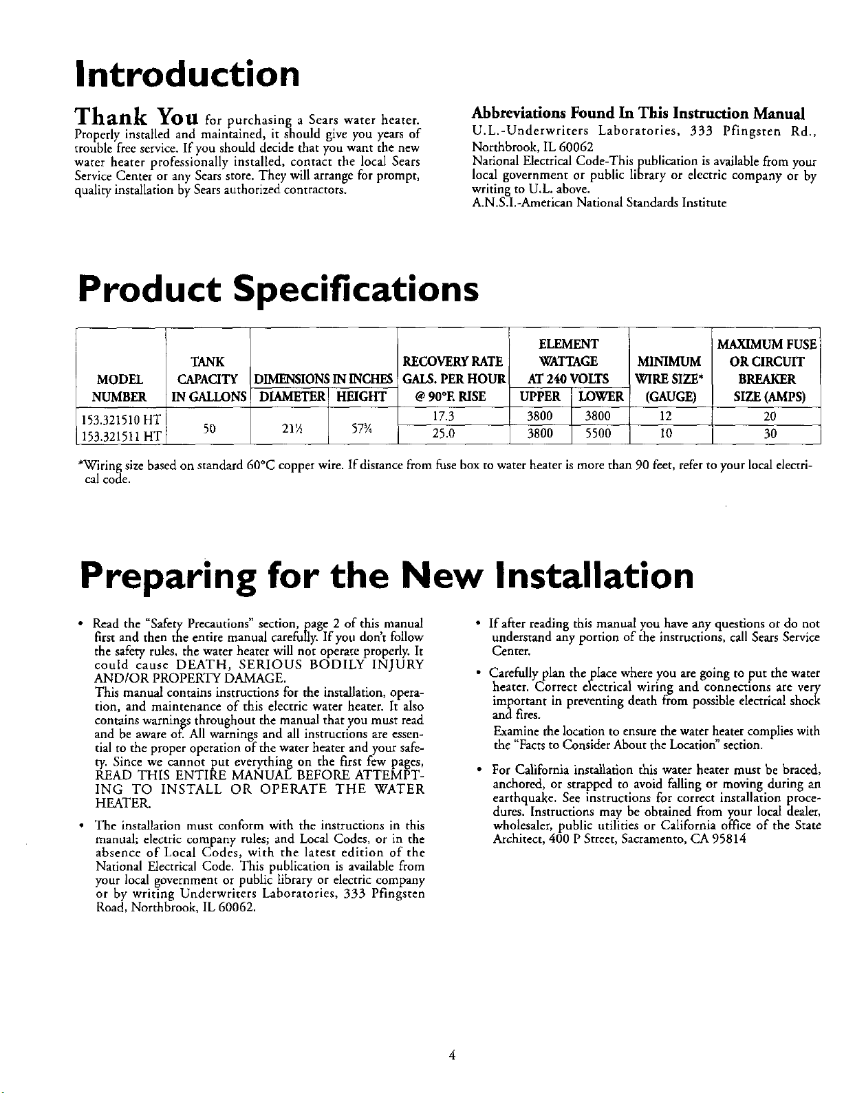
Product Specifications
ELEMENT
TANK
MODEL
NUMBER
153.321510HT
153.321511HT
*Wiring size based on standard 60°C copper wire. If distance from fuse box to water heater is more than 90 feet, refer to your local electri-
cal code.
CAPACITY
IN GALLONS
50
DIMENSIONSIN INCHES
DIAMETER HEIGHT
21½ 57_A
RECOVERYRATE
GALS.PERHOUR
@90°E RISE
17.3
25.0
WATTAGE MINIMUM
AT 240 VOLTS WIRE SIZE*
UPPER LOWER (GAUGE)
3800 3800 12
3800 5500 ] 10
I
MAXIMUM FUSE
OR CIRCUIT
BREAKER
SIZE (AMPS)
20
30
Preparing for the New Installation
• Read the "Safety Precautions" section, page 2 of this,manual
first and then the entire manual carefully. If you dont follow
the safety rules, the water heater will not operate properly. It
could cause DEATH, SERIOUS BODILY INJURY
AND/OR PROPERTY DAMAGE.
This manual contains instructions for the installation, opera-
tion, and maintenance of this electric water heater. It also
contains warnings throughout the manual that you must read
and be aware of. All warnings and all instructions are essen-
tial to the proper operation of the water heater and your safe-
ty. Since we cannot put everything on the first few pages,
READ THIS ENTIRE MANUAL BEFORE ATTEMPT-
ING TO INSTALL OR OPERATE THE WATER
HEATER.
• The installation must conform with the instructions in this
manual; electric company rules; and Local Codes, or in the
absence of Local Codes, with the latest edition of the
National Electrical Code. This publication is available from
your local government or public library or electric company
or by writing Underwriters Laboratories, 333 Pfingsten
Road, Northbrook, IL 60062.
• Ifafrer reading this manual you have any questions or do not
understand any portion of the instructions, call Sears Service
Center.
• Carefully plan theplace where you are going to put the water
heater. Correct electrical wiring and connections are very
important in preventing death from possible electrical shock
and fires.
Examine the location to ensure the water heater complies with
the "Facts to Consider About the Location" section.
• For California installation this water heater must be braced,
anchored, or strapped to avoid falling or moving during an
earthquake. See instructions for correct installation proce-
dures. Instructions may be obtained from your local dealer,
wholesaler, public utilities or California office of the State
Architect, 400 P Street, Sacramento, CA 95814
Materials and Basic Tools Needed
Materials Needed
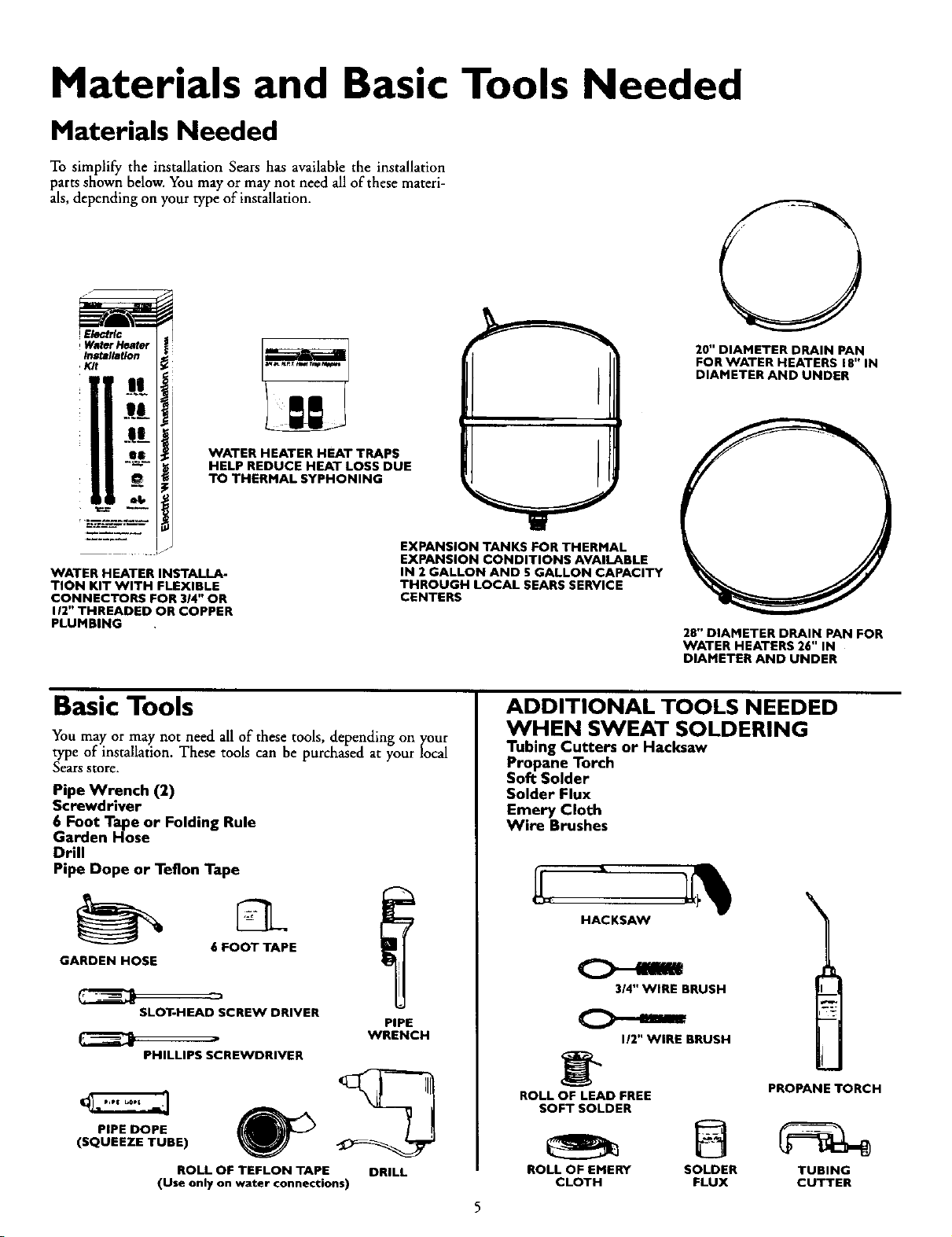
To simplify the installation Sears has available the installation
parts shown below. You may or may not need all of these materi-
als, depending on your type of installation.
20" DIAMETER DRAIN PAN
FOR WATER HEATERS 18" IN
DIAMETER AND UNDER
11:".
iF
II:',.ti
WATER HEATER HEAT TRAPS
HELP REDUCE HEAT LOSS DUE
TO THERMAL SYPHONING
EXPANSION TANKS FOR THERMAL
EXPANSION CONDITIONS AVAILABLE
WATER HEATER INSTALLA-
TION KIT WITH FLEXIBLE
CONNECTORS FOR 3/4" OR
I/2" THREADED OR COPPER
PLUMBING
IN 2 GALLON AND 5 GALLON CAPACITY
THROUGH LOCAL SEARS SERVICE
CENTERS
Basic Tools
You may or may not need all of these tools, depending on your
type of installation. These tools can be purchased at your local
Sears store.
Pipe Wrench (2)
Screwdriver
6 Foot Tape or Folding Rule
Garden Hose
Drill
Pipe Dope or Teflon Tape
GARDEN HOSE
SLOT-HEAD SCREW DRIVER
PHILLIPS SCREWDRIVER
PIPE DOPE
(SQUEEZE TUBE)
(Use only on water connections)
6 FOOT TAPE
ROLL OF TEFLON TAPE
PIPE
WRENCH
DRILL
28" DIAMETER DRAIN PAN FOR
WATER HEATERS 26" IN
DIAMETER AND UNDER
ADDITIONAL TOOLS NEEDED
WHEN SWEAT SOLDERING
Tubing Cutters or Hacksaw
Propane Torch
Soft Solder
Solder Flux
Emery Cloth
Wire Brushes
HACKSAW
314" WIRE BRUSH
I/2" WIRE BRUSH
_" PROPANE TORCH
ROLL OF LEAD FREE
SOFT SOLDER
ROLL OF EMERY SOLDER TUBING
CLOTH FLUX CUTTER
Installation Instructions
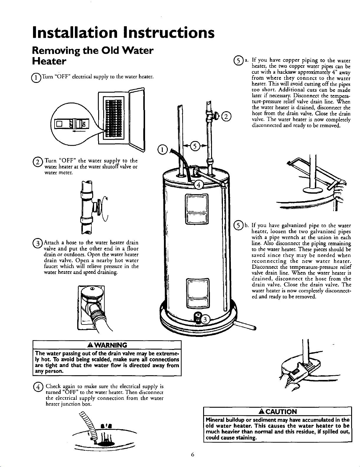
Removing the Old Water
Heater
QTurn "OFF" electricalsupply to the water heater.
Q Turn "OFF" the water supply to the
water heater at the water shutoffvalve or
water meter.
If you have copper piping to the water
a.
heater, the two copper water pipes ,canbe
cut with a hacksaw approximately 4 away
from where they connect to the water
heater. This will avoid cutting off the pipes
too short. Additional cuts can be made
later if necessary. Disconnect the tempera-
ture-pressure relief valve drain line. When
the water heater is drained, disconnect the
hose from the drain valve. Close the drain
valve. The water heater is now completely
disconnected and readyto be removed.
QAttach a hose to the water heater drain
valve and put the other end in a floor
drain or outdoors. Open the water heater
drain valve. Open a nearby hot water
faucet which will relieve pressure in the
water heater and speed draining.
AWARNING I
The water passingout of the drain valvemay beextreme- I
ly hot. To avoidbeing scalded, make sure all connections
are tight and that the water flow ,s directed away from
anyperson.
Q Check to make the electrical supply isagain
turned OFF" to the water heater. Then disconnect
the electrical supply connection from the water
heater junction box.
sure
Qb.
If you have galvanized pipe to the water
heater, loosen the twogalvanized pipes
with a pipe wrench at the union in each
line. Also disconnect the piping remaining
to the water heater. These pieces should be
saved since they may be needed when
reconnecting the new water heater.
Disconnect the temperature-pressure relief
valve drain line. When the water heater is
drained, disconnect the hose from the
drain valve. Close the drain valve. The
water heater is now completely disconnect-
ed and ready to be removed.
• .A.CAUTION
Mineral buildup or sediment may have accumulatedin the
old water heater. This causes the water heater to be I
much heavier than normal and this residue, if spilled out,
coud causestain ng.
6
Installation Instructions (cont'd)
Facts to Consider About the Facts to Consider About The
Location Convertible Lower Element
You should carefully choose an indoor location for the new
water heater, because the placement is a very important consid-
eration for the safety of the occupants in the building and for
the most economical use of the appliance. This water heater is
not intended for outdoor installation.
Whether replacing an old water heater or putting the water
heater in a new location, the following critical points must be
observed.
• The location selected should be indoors as close to and as
centralized with the water piping system as possible. This
water heater, as well as all water heaters, will eventually leak.
Do not install without adequate drainage provisions where
water flow will cause damage.
_,CAUTION
WATER HEATERS EVENTUALLY LEAK: Installation of
the water heater must beaccomplishedin sucha manner
that if the tank or any connectionsshouldleak, the flow of
water will not causedamageto the structure. When such
locationscannot be avoided, a suitable drain pan should
be installed under the water heater. Drain pansare avail-
able at your local Sears stores. Sucha drain pan must be
piped to an adequate drain. Under no circumstances is
the manufacturer or Searsto be held liablefor anywater
damage in connectionwith thiswater heater.
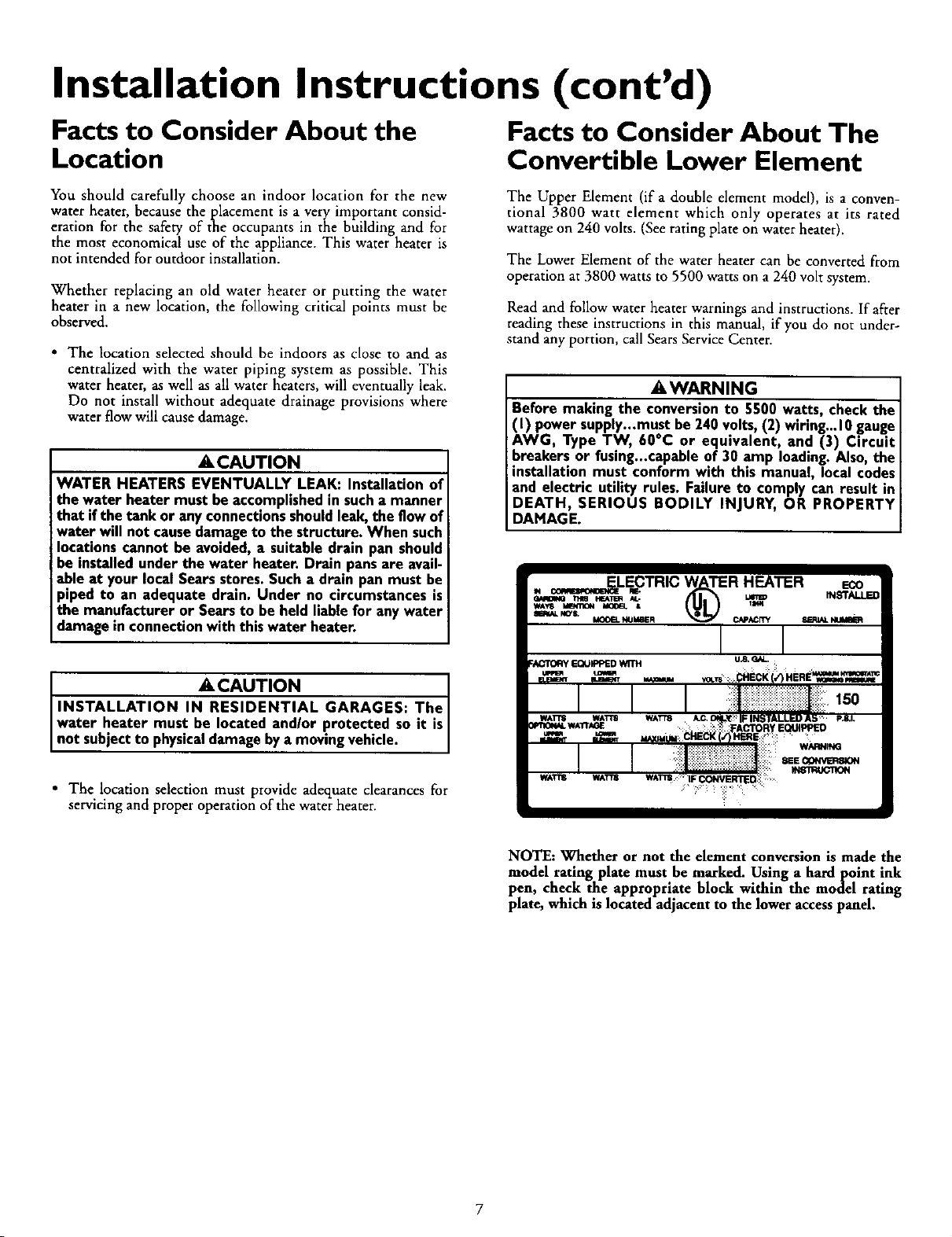
The Upper Element (if a double element model), is a conven-
tional 3800 watt element which only operates at its rated
wattage on 240 volts. (See rating plate on water heater).
The Lower Element of the water heater can be converted from
operation at 3800 watts to 5500 watts on a 24O volt system.
Read and follow water heater warnings and instructions. If after
reading these instructions in this manual, if you do not under-
stand any portion, call Sears Service Center.
_,WARNING
Before making the conversionto 5500 watts, check the
(I) power supply...must be 240volts,(2) wiring...10gauge
AWG, Type TW, 60oc or equivalent, and (3) Circuit
breakers or fusing...capableof 30 amp loading.Also,the
installation must conform with this manual, local codes
and electric utility rules. Failure to comply can result in
DEATH, SERIOUS BODILY INJURY, OR PROPERTY
DAMAGE.
ACAUTION J
INSTALLATION IN RESIDENTIAL GARAGES: The J
water heater must be located and/or protected so it is
not subjectto physicaldamage by a moving vehc e.
• The location selection must provide adequate clearances for
servicing and proper operation of the water heater.
NOTE: Whether or not the element conversion is made the
model rating plate must be marked. Using a hardpoint ink
pen, check the appropriate block within the model rating
plate, which is located adjacent to the lower access panel.
Installation Instructions (cont'd)
Water Piping
&WARNING
HOTTER WATER CAN SCALD: Water heaters are
intended to produce hot water. Water heated to a tem-
perature which will satisfyspaceheating,clothes washing,
dish washing, and other sanitizing needs can scald and
permanently injure you upon contact. Some people are
more likelyto be permanently injured by hot water than
others. These include the elderly, children, the infirm, or
physically/mentally handicapped. If anyone using hot
water in your home fits into one of these groups or if
there is a local code or state law requiring a certain tem-
Jerature water at the hot water tap, then you must take
specialprecautions. In addition to usingthe lowest possi-
ble temperature setting that satisfies your hot water
needs, a means such as a mixing valve, shall be used at
the hot water taps used by these people or at the water ;
heater. Mixing valvesare availableat plumbing supplyor
hardware stores. Follow manufacturers instructions for
installationof the valves.Before changingthe factory set-
ting on the thermostat, read the "Temperature
Regulation"section in this manual.
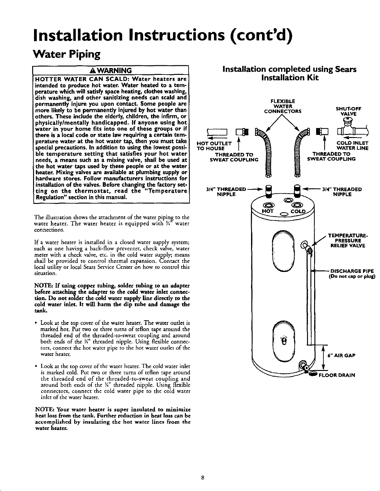
The illustration shows the attachment of the water plpin_ to the
water heater. The water heater is equipped with ¾ water
connections.
If a water heater is installed in a closed water supply system;
such as one having a back-flow preventer, check valve, water
meter with a check valve, etc. in the cold water supply; means
shall be provided to control thermal expansion. Contact the
local utility or local Sears Service Center on how to control this
situation.
NOTE: If using copper tubing, solder tubing to an adapter
before attaching the adapter to the cold water inlet connec-
tion. Do not solder the cold water supply fine directly to the
cold water inlet. It will harm the dip tube and damage the
tanl_
HOT OUTLET
--t
TO HOUSE
THREADED TO
SWEAT COUPLING
Installation completed using Sears
Installation Kit
FLEXIBLE
WATER SHUT-OFF
CONNECTORS VALVE
COLD INLET
WATER LINE
THREADED TO
SWEAT COUPLING
TEMPERATURE-
PRESSURE
RELIEF VALVE
(Do not cap or plug)
• Look at the top cover of the water heater. The water outlet is
marked hot. Put two or three turns of teflon tape around the
threaded end of the threaded-to-sweat coupling and around
both ends of the 3A"threaded nipple. Using flexible connec-
tors, connect the hot water pipe to the hot water outlet of the
water heater.
• Look at the top cover of the water heater. The cold water inlet
is marked cold. Put two or three turns of teflon tape around
the threaded end of the threaded-to-sweat coupling and
around both ends of the _" threaded nipple. Using flexible
connectors, connect the cold water pipe to the cold water
inlet of the water heater.
NOTE: Your water heater is super insulated to minimize
heat loss from the tank. Further reduction in heat loss can be
accomplished by insulating the hot water lines from the
water heater.
FLOOR DRAIN
Installation Instructions (cont'd)
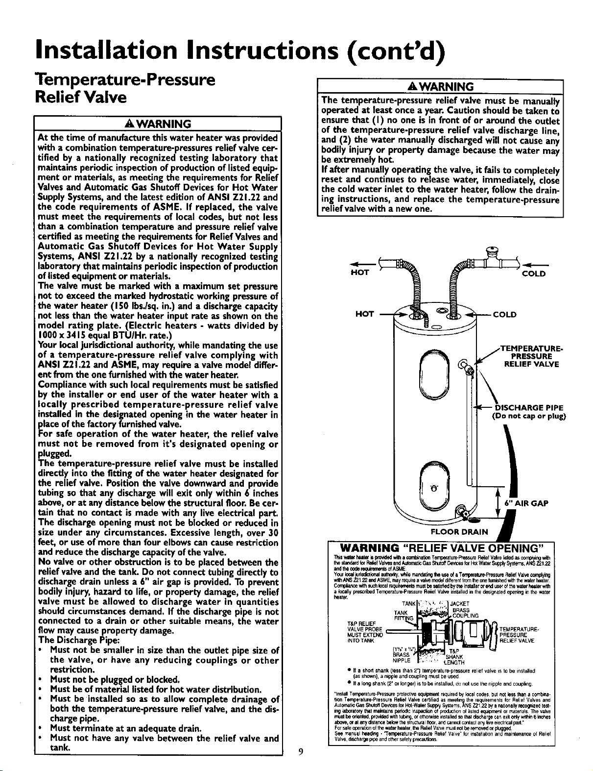
Temperature-Pressure
Relief Valve
,&WARNING
At the time of manufacturethis water heater wasprovided
with a combinationtemperature-pressuresrelief valvecer-
tified by a nationally recognized testing laboratory that
maintains periodic inspectionof productionoflistedequip-
ment or materials, as meeting the requirements for Relief
Valvesand Automatic Gas Shutoff Devicesfor Hot Water
SupplySystems,andthe latest edition of ANSI Z21.22 and
the code requirements of ASME. If replaced, the valve
must meet the requirements of local codes,but not less
than a combination temperature and pressurerelief valve
certified as meeting the requirements for ReliefValvesand
Automatic Gas Shutoff Devices for Hot Water Supply
Systems,ANSI Z21.22 by a nationally recognized testing
laboratory that maintainsperiodicinspectionof production
oflistedequipmentor materials.
The valve must be marked with a maximum set pressure
not to exceed the marked hydrostaticworking pressureof
the water heater (150 Ibs./sq.in.) and a dischargecapacity
not lessthan the water heater input rate as shownon the
model rating plate. (Electric heaters - watts divided by
1000x 3415equal BTU/Hr. rate.)
Yourlocaljurisdictionalauthority, while mandatingthe use
of a temperature-pressure relief valve complying with
ANSI 721.22 and ASME, may require a valve model differ-
ent from the onefurnishedwith the water heater.
Compliancewith suchlocal requirements must be satisfied
_y the installer or end user of the water heater with a
ocally prescribed temperature-pressure relief valve
nstalled in the designatedopeningin the water heater in
placeof thefactory furnishedvalve.
For safe operation of the water heater, the relief valve
must not be removed from it's designated opening or
plugged.
The temperature-pressure relief valve must be installed
directly into the fitting of the water heater designatedfor
the relief valve. Positionthe valve downward and provide
tubing so that any dischargewill exit only within 6 inches
above, or at anydistancebelowthe structuralfloor.Be cer-
tain that no contact is made with any live electrical part.
The dischargeopeningmust not be blockedor reduced in
size under any circumstances. Excessivelength, over 30
feet, or useof more than four elbowscancauserestriction
and reduce the dischargecapacityofthe valve.
No valveor other obstructionisto be placed between the
relief valve and the tank. Do not connect tubingdirectlyto
dischargedrain unlessa 6" air gap is provided.To prevent
bodilyinjury, hazard to life, or property damage,the relief
valve must be allowed to discharge water in quantities
shouldcircumstancesdemand. If the dischargepipe is not
connected to a drain or other suitable means, the water
flow may causeproperty damage.
The DischargePipe:
Must not be smaller in size than the outlet pipe size of
the valve, or have any reducing couplings or other
restriction.
Must not be pluggedor blocked.
Must beofmaterial listed for hot water distribution.
Must be installed so as to allow complete drainage of
both the temperature-pressure relief valve, and the dis-
chargepipe.
Mustterminate at anadequate drain.
Must not have any valve between the relief valve and
tank.
,&WARNING
The temperature-pressure relief valve must be manually
operated at least oncea year. Caution shouldbe taken to
ensure that (I) no one is infront of or around the outlet
of the temperature-pressure relief valve discharge line,
and (2) the water manually dischargedwill not causeany
bodily injury or property damage becausethe water may
be extremely hot.
If after manuallyoperating the valve,it failsto completely
reset and continues to release water, immediately, close
the cold water inlet to the water heater,follow the drain-
ing instructions, and replace the temperature-pressure
relief valve with anew one.
HOT
HOT
RELIEF VALVE
(Do not cap or plug)
6" AIR GAP
WARNING "RELIEF VALVE OPENING"
_,,s witet heaterb provldedwi'hacombinaUonTemperature-PP",=_suteP_ief Valvellstedasascomp,y_ _th
thestandardiorP,_f ValvesandA_omalicGasShtoff_ncestarP,_WaterSupply$yste'_s,AN__122
andthe codereq_JremerdsofASME
Y_r local rf_ional author_,v_le ritar_b'lg theuseo__Temperate-PressureRelielVa_ complying
*ith,_S ;_ 22andA_E, mayrngu_a,_ moderdifterer_Iromthec,_e_Jr_ed _ _ w_r _r
C0mptancevAthsuchlocaln_u_ementsmustbe satsSedbytheinstalerorend_ ofthewat_ healerwith
a locally p,escril_dTemberatute-Pre_uteRefel Val_ instaJledinthedesig_ted openingin1bewalei
TANK BRASS
T&P RELIEF
VALVE PROBE _TEMPERATURE-
INTO TANK I RELIEF VALVE
BRASS _ SHANK
NIPPLE LENGTH
• I1 a shorl stlank (_essthan2") temperature-pressurerelief valve isto be installed
(as shown),a nipple and couplingmust beused
• If a long shank;(2' or longer)is to be installed, donot useIhe nippleand coupling
=InstallTemperature-Pressesprate:tireequipt_nt requiredby k:,cal cedes bulnot lessthan a coml_na-
lion Tempetalure-PresseraReliefValve certifiedas meeting the requirementsforRelief Valvesand
AutoreaticGasSh_offDevtcesforHal-WaterSupp'ySystems,ANSZ2_22 bya nat_'lallyrecognizedtest-
inglaboratorythatmaJr_r_ pedodicit_specli0_OfproductK)noflisted equ_rn_l or rnatenaqs131evalve
muslbe onantsd,p,ovid_ withlUbng,o_othenvtseinstzlledsothatd_harge ca_ exil c_lywdl_n6inches
above,orat anydislar_ belowthestruc_ura_to3r, andcanno_conlaClartylivee_eclr_alpad•
ForsafeoperationofIt_ waistheater,theReliefValvemustPotbe ,emovedor plugged
See manualheed_g. "Temperature-PressuleReliefValve"for installationandmaintenanceol Relief
Valve,diS_hai_ep_peandothersafelypr_attic_s
9
JACKET
COUPLING
PRESSURE
T&P
COLD
E.
PRESSURE
E
 Loading...