

Kenmore 153.320493 User Manual
K^nmor^
Owners
Manual
FOR POTABLE WATER
HEATING ONLY
NOT SUITABLE FOR
SPACE HEATING
Model No.
153.320392 HT
153.320393 HT
153.320492 HT
153.320493 HT
153.320592 HT
153.320593 HT
153.320692 HT
153.320693 HT
153.320892 HT
153.320893 HT
30 Gal,
30 Gal.
40 Gal.
40 Gal.
50 Gal.
50 Gal.
66 Gal.
66 Gal.
80 Gal.
80 Gal.
Caution:
Read and Follow
Ail Safety Rules and
Operating Instructions
Before First Use of
This Product.
Save this Manual for Future Reference.
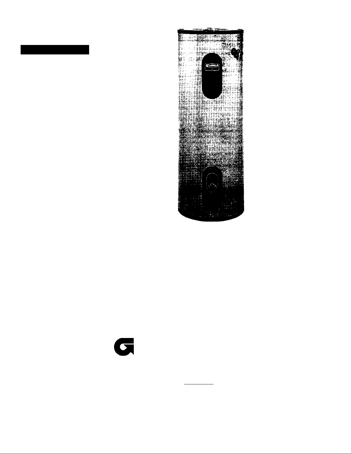
POWER MISERY” 12
WATER HEATER
Safety Instructions
Installation
Operation
EFFICIENCY
RATING
ama
READ THE GENERAL SAFETY SECTION BEGINNING ON INSIDE COVER
AND THEN THIS ENTIRE MANUAL BEFORE INSTALLING OR OPERAT
ING THIS WATER HEATER.
GAMA certification applies to all residential electric water heaters with
capacities of 20 to 120 Gallons. Input rating of 12 Kw or less at a voltage
no greater than 250 V.
Care and Maintenance Troubleshooting Parts List
Awarning
Sears, Roebuck and Co., Hoffman Estates, IL 60179 U.S.A.

Safety
A WARNING
Improper installation, adjustment, alteration, service or mainte
nance can cause DEATH, SERIOUS BODILY INJURT, OR PROP
ERTY DAMAGE. Refer to this manual for assistance or consult
your local Sears Service Center for further information.
A WARNING
At the time of manufacture this water heater was provided with
a combination temperature-pressures relief valve certified by a
nationally rec(^niz«J testing laboratory that maintains periodic
inspection of production of listed equipment or materials, as
meeting the requirements for Relief Valves and Automatic Gas
Shutoff Devices for Hot Water Supply Systems, and the latest
edition of ANSI Z2I.22 and the code requirements of ASME. If
replaced, the valve must meet the requirements of local codes,
but not less than a combination temperature and pressure relief
valve certified as meeting the requirements for Relief Valves and
Automatic Gas Shutoff Devices for Hot Water Supply Systems,
ANSI Z2I.22 by a nationally recognized testing laboratory that
maintains periodic inspection of production of listed equipment
or materials.
The valve must be marked with a maximum set pressure not to
exceed the marlœd hydrostatic working pressure of the water
heater (ISO IbsJsq. in.) and a discharge capacity not less than the
water heater input rate as shown on the model rating plate.
(Electric heaters - watts divided by 1000 x 3415 equal BTU/Hr.
rate.)
Your local jurisdictional authority, while mandating the use of a
temperature-pressure relief valve complying witii ANSI Z2I.22
and ASME, may require a valve model different from the one fur
nished with the water heater.
Compliance with such local requirements must be satisfied by
the installer or end user of the water heater with a locally pre
scribed temperature-pressure relief valve installed in the desig
nated opening in the water heater in place of the factory fornished valve.
For safe operation of the water heater, the relief valve must not
be removed from itis designated opening or plugged.
The temperature-pressure relief valve must be installed directly
into the fitting of the water heater designated for the relief valve.
Position the valve downward and provide tubing so that any dis
charge will exit only within 6 inches above, or at any distance
below the structuré floor. Be certain that no contact is made
with any live electrical part. The discharge opening must not be
blocked or reduced in size under any circumstances. Excessive
length, over 30 feet, or use of more than four elbows can cause
restriction and reduce the discharge capacity of the valve.
No valve or other obstruction is to be placed between the relief
valve and the tank. Do not connect tubing directly to discharge
drain unless a 6" air gap is provided. To prevent bodily injury, haz
ard to life, or property damage, the relief valve must be allowed
to discharge water in quantities should circumstances demand. If
the discharge pipe is not connected to a drain or other suitable
means, the water flow may cause property damage.
The Discharge Pipe:
• Must not be smaller in size than the outlet pipe size of the
valve, or have any reducing couplings or other restrictions.
• Must not be plugged or blocked.
* Must be of material listed for hot water distribution.
* Must be installed so as to allow complete drainage of
both the temperature-pressure relief valve, and the
discharge pipe.
* Must terminate at an adequate drain.
• Must not have any valve between the relief valve and tank.
A WARNING
HAZARD OF ELECTRICAL SHOCK! Before removing any
access panels or servicing the water heater, make sure the
electrical supply to the water heater is turned “OFF". Failure
to do this could result in DEATH, SERIOUS BODILY INJU'
OR PROPERTY DAMAGE.
AWARNING
HOTTER WATER CAN SCALD: Water heaters are intended
to produce hot water. Water heated to a temperature which
will satisfy space heating, clothes washing, dish washing, and
other sanitizing needs can scald and permanently injure you
upon contact. Some people are more likely to be permanent
ly injured by hot water than others. These include the elderly,
children, the infirm, or physically/mentally handicapped. If
anyone using hot water in your home fits into one of these
groups or if there is a locai code or state iaw requiring a cer
tain temperature water at the hot water tap, then you must
take special precautions. In addition to using the lowest possi
ble temperature setting that satisfies your hot water needs, a
means such as a mixing valve, shall be used at the hot water
taps used by these people or at the water heater. Mixing
valves are available at plumbing supply or hardware stores.
Follow manufacturers instructions for installation of the
valves. Before changing the factory setting on the thermo
stat, read the "Temperature Regulation" section in this
manual.
AWARNING
WATER HEATERS EQUIPPED FOR ONE VOLTAGE ONLY:
This water heater is equipped for one type voltage only.
Check the rating plate near the bottom access panel for the
correct voltage. DO NOT use this water heater with any volt
age other than the one shown on the model rating plate
Failure to use the correct voltage can cause problems which
can result in DEATH, SERIOUS BODILY INJURY, OR PROP
ERTY DAMAGE. If you have any questions or doubts consult
your electric company.
AWARNING
INSULATING JACKETS; When installing an external water
heater insulation jacket on an electric water heater:
a. DO NOT cover the temperature-pressure relief valve.
b. DO NOT put insulation over the access covers or any
access areas.
c. DO NOT cover or remove operating instructions, and safe
ty related warning labels and materials affixed to the water
heater.
AWARNING
Do not use this appliance if any part of it has been under
water. An electrical short or malfunction could occur. The
water heater should be replaced.
A CAUTION
WATER HEATERS EVENTUALLY LEAK: Installation of the
water heater must be accomplished in such a manner that tf
the tank or any connections should leak, the flow of water
will not cause damage to the structure. For this reason, it is
not advisable to install the water heater in an attic or upper
floor. When such locations cannot be avoided, a suitable
drain pan should be installed under the water heater. Drain
pans are available at your local Sears Store. Such a drain pan
must be piped to an adequate drain. Under no circumstances
is the manufacturer or Sears to be held liable for any water
damage in connection with this water heater.

Table of Contents
Safety Precautions................................................................................................................................................................................................2
Table of Contents..................................................................................................................................................................................................3
Introduction........................................................................................................................................................................................................4
Product Specifications........................................................................................................................................................................................ 4
Preparing for the New Installation..................................................................................................................................................................... 4
Materials and Basic Tools Needed.......................................................................................................................................................................5
Materials Needed....................................................................................................................................................................................... 5
Basic Tools.....................................................................................................................................................................................................
Installation Instructions.................................................................................................................................................................................6-15
Removing the Old Water Heater................................................................................................................................................................. 6
Facts to Consider About the Location...........................................................................................................................................................7
Facts to Consider About the Convertible Lower Element............................................................................................................................. 7
Water Piping..................................................................................................................................................................................................
Temperature-Pressure Relief Valve....................................................................................................................................................... 9
Filling the Water Heater..............................................................................................................................................................................
Converting the Lower Element........................................................................................................................................................... 10-12
Wiring Diagrams...................................................................................................................................................................................... I3
Wiring..................................................................................................................................................................................................... 14
Installation Checklist................................................................................................................................................................................. I5
..
..
.
Service and Adjustment................................................................................................................................................................................16.20
Temperature Regulation...................................................................................................................................................................... Ig
Thermostats......................................................................................................................................................................................... Ig
Thermostat Settings................................................................................................................................................................................. Ig
Upper Thermostat Adjustment................................................................................................................................................................ Ig
Lower Thermostat Adjustment............................................................................................................................................................... I7
Temperature-Pressure Relief Valve Operation....................................................................................................................................... I7
Draining.................................................................................................................................................................................................... 17
Element Cleaning and Replacement............................................................................................................................................... „.18-20
Drain Valve Washer Replacement............................................................................................................................................................ 20
Service....................................................................................................................................................................................................... 20
Troubleshooting Guide.................................................................................................................................................................................21-24
Start Up Conditions.................................................................................................................................................................................... 21
Thermal Expansion.................................................................................................................................................................................. 21
Strange Sounds.........................................................................................................................................................................................21
Operational Conditions........................................................................................................................................................................22-23
Smelly Water............................................................................................................................................................................................ 22
Air in Hot Water Faucet’s.........................................................................................................................................................................22
Rumbling Noise..................................................................................................................................................................................... 22
High Temperature Shut Off System.................................................................................................................................................. .22-23
Not Enough or No Hot Water...................................................................................................................................................................23
Water is Too Hot..................................................................................................................................................................................... 23
Leakage Checkpoints................................................................................................................................................................................. 24
Parts Order List........................................................................................................................................................................................... 28-31
^'^rranty............................................................................................................................................................................................................
..

Introduction
Thank You for purchasing a Sears water heater.
Properly installed and maintained, it should give you years of
trouble free service. If you should decide that you want the new
water heater professionally installed, contact the local Sears
Service Center or any Sears store. They will arrange for prompt,
quality installation by Sears authorized contractors.
Product Specifications
MODEL
NUMBER
153.320392 HT
153.320393 HT
153.320492 HT
153.320493 HT
153.320592 HT
153.320593 HT
153.320692 HT
153.320693 HT
153.320892 HT
153.320893 HT
TANK
CAPACITY
IN GALLONS
30 20 46/4
40 20 60/
50
66 24
80
DIMENSIONS IN INCHES
DIAMETER
22 58/
26/4 62
HEIGHT
61
RECOVERY RATE
GALS. PER HOUR
@ 90“F. RISE
17.3 3800 3800 12
25.0 3800
17.3 3800
25.0 3800
17.3
25.0
17.3 3800 3800 12
25.0
17.3 3800 3800
25.0
Abbreviations Found In This Instruction Manual
U.L.-Underwriters Laboratories, 333 Pfingsten R
Northbrook, IL 60062
National Electrical Code-This publication is available from your
local government or public library or electric company or by
writing to U.L. above.
ANSl-American National Standards Institute
ELEMENT
WATTAGE
AT 240 VOLTS
UPPER LOWER
5500 10
3800 12
5500 10
3800
3800 5500
3800
3800
3800 12
5500 10
5500 10
MINIMUM
WIRE SIZE*
(GAUGE)
10
12
MAXIMUM FUSE
OR CIRCUIT
BREAKER
SIZE (AMPS)
20
30
20
30
20
30
20
30
20
30
*Wiring size based on standard 60°C copper wire. If distance from fuse box to water heater is more than 90 feet, refer to your local electri
cal code.
Preparing for the New Installation
Read the “Safety Precautions” section, page 2 of this manual
first and then the entire manual carefully. If you don’t follow
the safety rules, the water heater will not operate properly. It
could cause DEATH, SERIOUS BODILY INJURY
AND/OR PROPERTY DAMAGE.
This manual contains instructions for the installation, opera
tion, and maintenance of this electric water heater. It also
contains warnings throughout the manual that you must read
and be aware of. All warnings and all instructions are essen
tial to the proper operation of the water heater and your safe
ty. Since we cannot put everything on the first few pages,
READ THIS ENTIRE MANUAL BEFORE ATTEMPT
ING TO INSTALL OR OPERATE THE WATER
HEATER.
The installation must conform with the instructions in this
manual; electric company rules; and Local Codes, or in the
absence of Local Codes, with the latest edition of the
National Electrical Code. This publication is available from
your local government or public library or electric company
or by writing Underwriters Laboratories, 333 Pfingsten
Road, Northbrook, IL 60062.
If after reading this manual you have any questions or do not
understand any portion of the instructions, call Sears Service
Center.
Carefully plan the place where you are going to put the water
heater. Correct electrical wiring and connections are very
important in preventing death from possible electrical shock
and fires.
Examine the location to ensure the water heater complies with
the “Facts to Consider About the Location” section.
For California installation this water heater must be braced,
anchored, or strapped to avoid falling or moving during an
earthquake. See instructions for correct installation proce
dures. Instructions may be obtained from your local dealer,
wholesaler, public utilities or California office of the State
Architect, 400 P Street, Sacramento, CA 95814
Materials and Basic Tools Needed
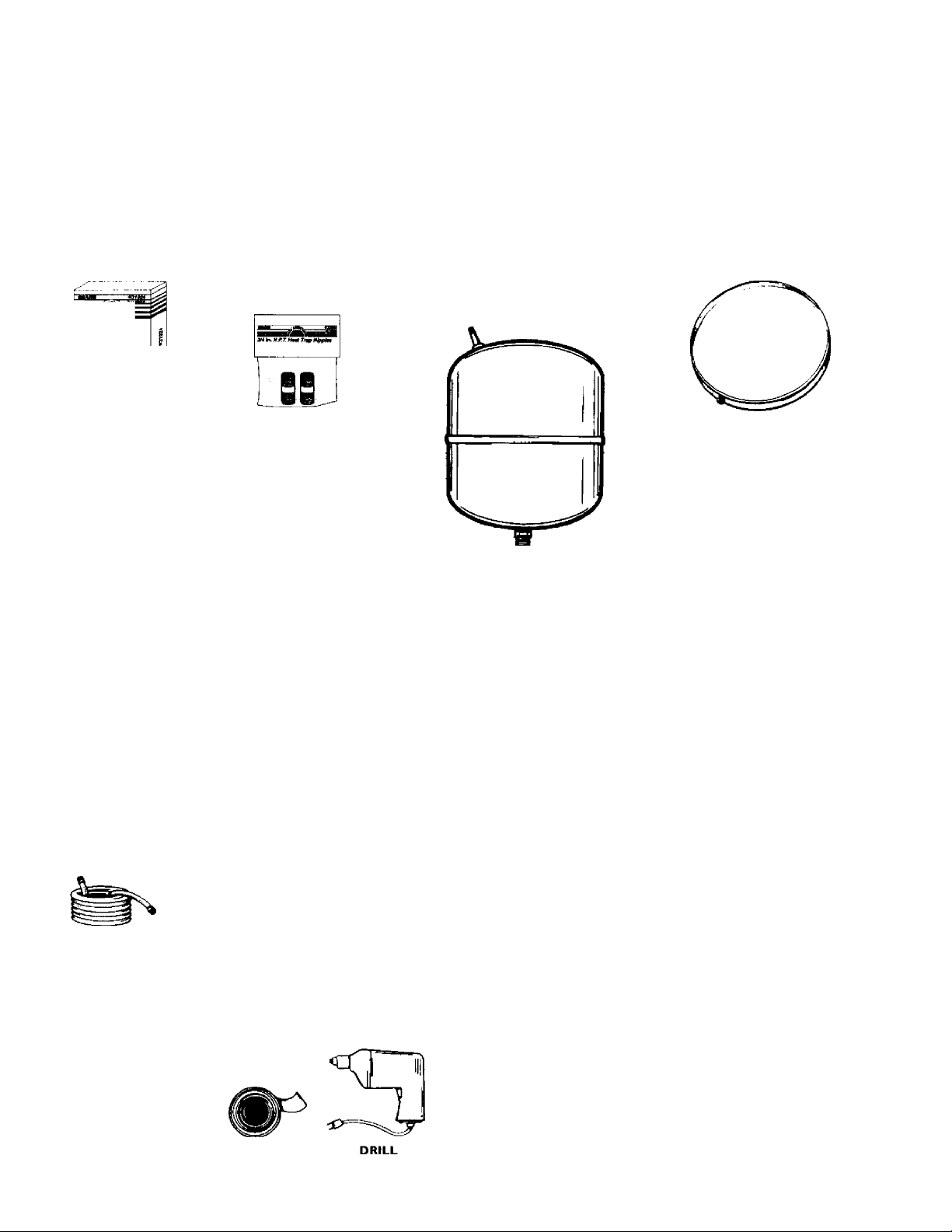
Materials Needed
To simplify the installation Sears has available the installation
parts shown below. You may or may not need all of these materi
als, depending on your type of installation.
Electric
Water Heater
Installation
Kit
ii
ML
it
-ftf-
e
WATER HEATER HEAT TRAPS
HELP REDUCE HEAT LOSS DUE
TO THERMAL SYPHONING
DRAIN PANS AVAILABLE IN 20"
DIAMETER FOR WATER HEATERS
HAVING A DIAMETER 18" OR LESS,
24" DIAMETER FOR WATER HEATERS
HAVING A DIAMETER 22" OR LESS
AND AVAILABLE IN 28" DIAMETER
FOR WATER HEATERS HAVING A
DIAMETER 26" OR LESS
WATER HEATER INSTALLA
TION KIT WITH FLEXIBLE
CONNECTORS FOR 3/4" OR
I/Z" THREADED OR COPPER
LUMBING
EXPANSION TANKS FOR THERMAL
EXPANSION CONDITIONS AVAILABLE
IN 2 GALLON AND 5 GALLON CAPACITY
THROUGH LOCAL SEARS SERVICE
CENTERS
Basic Tools
You may or may not need all of these tools, depending on your
type of installation. These tools can be purchased at your local
Seats store.
Pipe Wrench (2)
Screwdriver
6 Foot Tape or Foiding Rule
Garden Hose
Drili
Pipe Dope or Teflon Tape
GARDEN HOSE
SLOT-HEAD SCREW DRIVER
PHILLIPS SCREWDRIVER
6 FOOT TAPE
PIPE
WRENCH
ADDITIONAL TOOLS NEEDED
WHEN SWEAT SOLDERING
Tubing Cutters or Hacksaw
Propane Torch
Soft Soider
Solder Flux
Emery Cloth
Wire Brushes
HACKSAW
3/4" WIRE BRUSH
1/2" WIRE BRUSH
\
A
P.PI 4.0*1
PIPE DOPE
(SQUEEZE TUBE)
(Use only on water connections)
ROLL OF TEFLON TAPE
ROLL OF LEAD FREE
SOFT SOLDER
ROLL OF EMERY
CLOTH
SOLDER
FLUX
PROPANE TORCH
nà-g
TUBING
CUTTER
Installation Instructions
Removing the Old Water Heater
^^Turn “OFF” electrical supply to the water heater.
lElllli
r5ja. If you have copper piping to the wsi^^CT
heater, the two copper water pipes can be
cut with a hacksaw approximately 4" away
from where they connect to the water
heater. This will avoid cutting off the pipes
too short. Additional cuts can be made
later if necessary. Disconnect the tempera
ture-pressure relief valve drain line, ’'^en
the water heater is drained, disconnect the
hose from the drain valve. Close the drain
valve. The water heater is now completely
disconnected and ready to be removed.
Turn “OFF
water heater
water meter.
Attach a hose to the water heater drain
©
valve and put the other end in a floor
drain or outdoors. Open the water heater
drain valve. Open a nearby hot water
faucet which will relieve pressure in the
water heater and speed draining.
” the water supply to t
at the water shutoff valve
the
or
b. If you have galvanized pipe to the water
heater, loosen the two galvanized pipej
with a pipe wrench at the union in eadri
line. Also disconnect the piping remaining
to the water heater. These pieces should be
saved since they may be needed when
reconnecting the new water heater.
Disconnect the temperature-pressure relief
valve drain line. When the water heater is
drained, disconnect the hose from the
drain valve. Close the drain valve. The
water heater is now completely disconnect
ed and ready to be removed.
A WARNING
The water passing out of the drain valve may be extreme
ly hot. To avoid being scalded, make sure all connections
are tight and that the water flow is directed away from
any person.
^4 J Check again to make sure the electrical supply is
turned “OFF” to the water heater. Then disconnect
the electrical supply connection from the water
heater junction box.
A CAUTION
Mineral buildup or sediment may have accumulated in the
old water heater. This causes the water heater to be
much heavier than normal and this residue, if spilled out,
could cuise staining.
Installation Instructions (contad)
Facts to Consider About the Location
You should carefully choose an indoor location for the new
water heater, because the placement is a very important consid
eration for the safety of the occupants in the building and for
the most economical use of the appliance. This water heater is
not intended for outdoor installation.
Whether replacing an old water heater or putting the water
heater in a new location, the following critical points must be
observed.
• The location selected should be indoors as close to and as
centralized with the water piping system as possible. This
water heater, as well as all water heaters, will eventually leak.
Do not install without adequate drainage provisions where
water flow will cause damage.
A CAUTION
WATER HEATERS EVENTUALLY LEAK: Installation of
the water heater must be accomplished in such a manner
that if the tank or any connections should leak, the flow of
water will not cause damage to the structure. For this
reason, it is not advisable to install the water heater in an
attic or upper floor. When such locations cannot be avoid
ed, a suitable drain pan should be installed under the
water heater. Drain pans are available at your local Sears
stores. Such a drain pan must be piped to an adequate
drain. Under no circumstances is the manufacturer or
Sears to be held liable for any water damage in connec
tion with this water heater.
Facts to Consider About The
Convertible Lower Element
The Upper Element (if a double element model), is a conven
tional 3800 watt element which only operates at its rated
wattage on 240 volts. (See rating plate on water heater).
The Lower Element of the water heater can be converted from
operation at 3800 watts to 5500 watts on a 240 volt system.
Read and follow water heater warnings and instructions. If after
reading these instructions in this manual, if you do not under
stand any portion, call Seats Service Center,
A WARNING
Before making the conversion to 5500 watts, check the
(I) power supply...must be 240 volts, (2) wiring... 10 gauge
AWG, Type TW, 60*C or equivalent, and (3) Circuit
breakers or fusing...capable of 30 amp loading. Also, the
installation must conform with this manual, local codes
and electric utility rules. Failure to comply can result in
DEATH, SERIOUS BODILY INJURY, OR PROPERTY
DAMAGE.
A CAUTION
INSTALLATION IN RESIDENTIAL GARAGES; The
water heater must be located and/or protected so it is
not subject to physical damage by a moving vehicle.
The location selection must provide adequate clearances for
servicing and proper operation of the water heater.
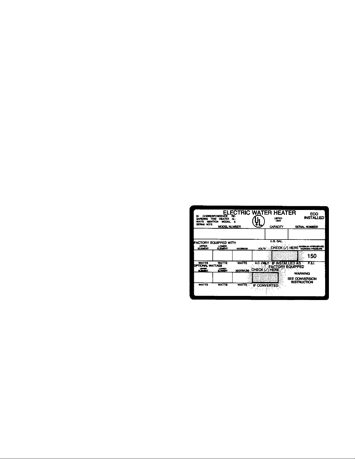
NOTE: Whether or not the element conversion is made the
model rating plate must be marked. Using a hard point ink
pen, check the appropriate block within the model rating
plate, which is located adjacent to the lower access panel.
Installation Instructions (cont*d)
Water Piping
AWARNING
HOTTER WATER CAN SCALD: Water heaters are
intended to produce hot water. Water heated to a tem
perature which will satisfy space heating, clothes washing,
dish washing, and other sanitizing needs can scald and
permanently injure you upon contact. Some people are
more likely to be permanently injured by hot water than
others. These include the elderly, children, the infirm, or
physically/mentally handicapped. If anyone using hot
water in your home fits into one of these groups or if
there is a local code or state law requiring a certain tem
perature water at the hot water tap, then you must take
special precautions. In addition to using the lowest possi
ble temperature setting that satisfies your hot water
needs, a means such as a mixing valve, shall be used at
the hot water taps used by these people or at the water
heater. Mixing valves are available at plumbing supply or
hardware stores. Follow manufacturers instructions for
installation of the valves. Before changing the factory set
ting on the thermostat, read the “Temperature
Regulation” section in this manual.
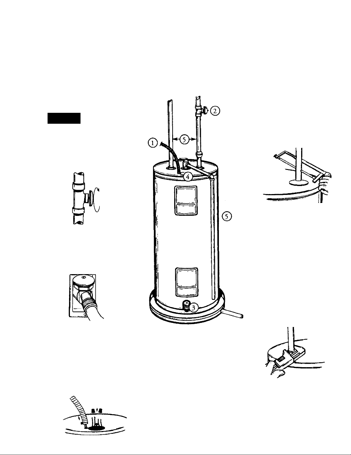
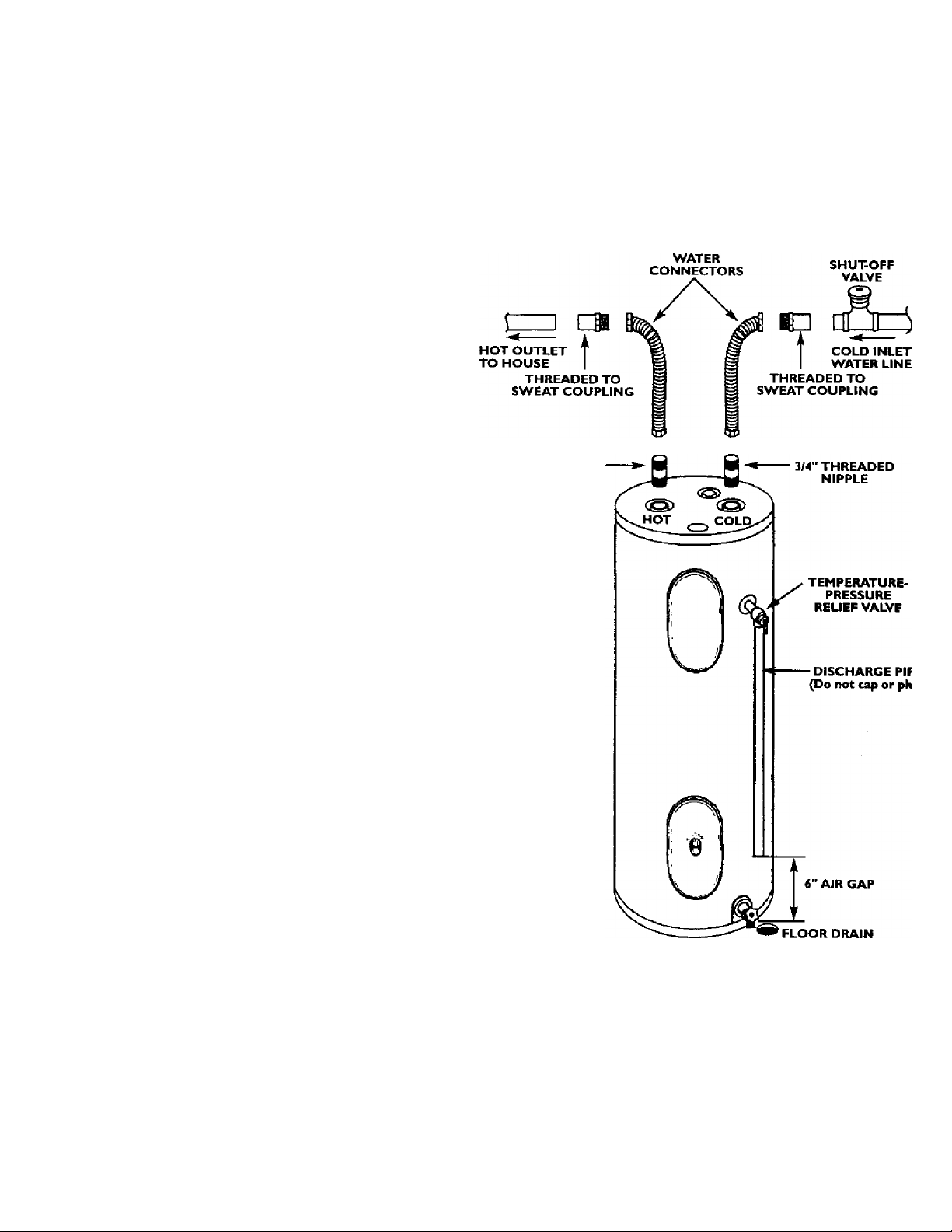
The illustration shows the attachment of the water piping to the
water heater. The water heater is equipped with Va water
connections.
If a water heater is installed in a closed water supply system;
such as one having a back-flow preventer, check valve, water
meter with a check valve, etc. in the cold water supply; means
shall be provided to control thermal expansion. Contact the
local utility or local Sears Service Center on how to control this
situation.
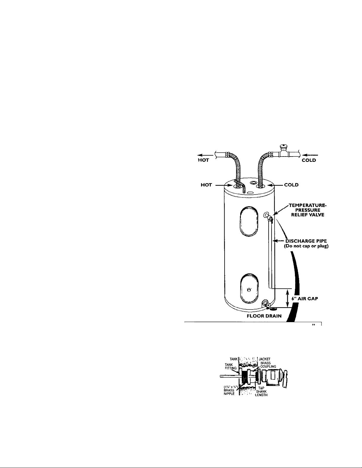
Installation completed using Sears
Installation Kit
FLEXIBLE
3/4’'
THREADED
NIPPLE
NOTE: If using copper tubing, solder tubing to an adapter
before attaching the adapter to the cold water inlet connec
tion. Oo not solder the cold water supply line directly to the
cold water inlet. It will harm the dip tube and damage the
tank.
• Look at the top cover of the water heater. The water outlet is
marked hot. Put two or three turns of teflon tape around the
threaded end of the threaded-to-sweat coupling and around
both ends of the threaded nipple. Using flexible connec
tors, connect the hot water pipe to the hot water outlet of the
water heater.
• Look at the top cover of the water heater. The cold water inlet
is marked cold. Put two or three turns of teflon tape around
the threaded end of the threaded-to-sweat coupling and
around both ends of the threaded nipple. Using flexible
connectors, connect the cold water pipe to the cold water
inlet of the water heater.
NOTE; Your water heater is super insulated to minimize
heat loss from the tank. Farther reduction in heat loss can be
accomplished by insulating the hot water lines from the
water heater.
installation Instructions (contad)
Temperature-Pressure Relief Valve
A WARNING
At the time of manufacture this water heater was provided with
a combination temperature-pressures relief valve certified by a
nationally recognized testing laboratory that maintains periodic
inspection of production of listed equipment or materials, as
meeting the requirements for Relief Valves and Automatic Gas
Shutoff Devices for Hot Water Supply Systems, and the latest
edition of ANSI Z2I.22 and the code requirements of ASME. If
replaced, the valve must meet the requirements of local codes,
but not less than a combination temperature and pressure relief
valve certified as meeting the requirements for Relief Valves and
Automatic Gas Shutoff Devices for Hot Water Supply Systems,
ANSI Z2I.22 by a nationally recognized testing laboratory that
maintains peric^ic inspection of production of listed equipment
or materials.
The valve must be marked with a maximum set pressure not
to exceed the marked hydrostatic working pressure of the
water heater (ISO IbsJsq. in.) and a discharge capacity not
less than the water heater input rate as shown on the model
rating plate. (Electric heaters - watts divided by 1000 x 3415
equal BTU/Hr. rate.)
Your local jurisdictional authority, while mandating the use of a
temperature-pressure relief valve complying with ANSI Z2I.22
and ASME, may require a valve model different from the one fur
nished with the water heater.
Compliance with such local requirements must be satisfied by
the installer or end user of the water heater with a locally pre
scribed temperature-pressure relief valve installed in the desig
nated opening in the water heater in place of the factory fur
nished vialve.
For safe operation of the water heater, the relief valve must not
be removed from itis designated opening or plugged.
The temperature-pressure relief valve must be installed directly
into the fitting of the water heater designated for the relief valve.
Position the valve downward and provide tubing so that any dis
charge will exit only within 6 inches above, or at any distance
below the structural floor. Be certain that no contact is made
; with any live electrical part The discharge opening must not be
blocked or reduced in size under any circumstances. Excessive
length, over 30 feet, or use of more than four elbows can cause
restriction and reduce the discharge capacity of the valve.
No valve or other obstruction is to be placed between the relief
valve and the tank. Do not connect tubing directly to discharge
drain unless a 6" air gap is provided. To prevent bodily injury,
. hazard to life, or property damage, the relief valve must be
allowed to discharge water in quantities should circumstances
demand. If the discharge pipe is not connected to a drain or
other suitable means, the water flow may cause property
damage.
The Discharge Pipe:
• Must not be smaller in size than the outlet pipe size of the
valve, or have any reducing couplings or other restrictions.
> Must not be plugged or blocked.
* Must be of material listed for hot water distribution.
> Must be installed so as to allow complete drainage of both
the temperature-pressure relief valve, and the discharge
i pipe.
' * Must terminate at an adequate drain.
I * Must not have any valve between the relief valve and tank.
A WARNING
The temperature-pressure relief valve must be manually
operated at least once a year. Caution should be taken to
ensure that ( I ) no one is in front of or around the outlet
of the temperature-pressure relief valve discharge line,
and (2) the water manually discharged will not cause any
bodily injury or property damage because the water may
be extremely hot.
If after manually operating the valve, it fails to completely
reset and continues to release water, immediately, close
the cold water inlet to the water heater, follow the drain
ing instructions, and replace the temperature-pressure
relief valve with a new one.
WARNING “RELIEF VALVE OPENING
This water heater is provided with a combination Temperature-Pressure Relief Valve listed as complying with
the standard tor Reliel Valves and Autorrialic Sa$ Shutott Devicestor Hot Water Sup^ Systems. ANS^L^
and the code raqulnaments of ASMEYojr localJurisdichonal authority, while mandating the use of a Temperature-Pressure Reief Valve comptying
with ANS ¿21.22 and ASME, may require a valve rrodel different from the one lumished with the water heater.
Compliance with such locai requirements must he satisfied by the Installer or erxj user ot the water heater with
a locally prescribed Temperature-Pressure Relief Valve installed in the designated opertir^g in the water
heater.
T&P RELIEF
VALVE PROBE
MUST EXTEND
INTO TANK
• If a short shank {less than 2‘] lempefalure-pressure
(as shown), a nipple and coupling must be used-
• If a lor^g shank (2' or loriger) is to be installed, do not
Install Temperatue-Pressure protective equipment required by local codes, but not less than a combina
tion Temperature-Pressure Reiief Valve certified as meeting the requirements lor Relief Valves and
Automatic Gas Shutoff Devices for Hoi-Water Supply Systems, ANS Z21.22 by a naiionaHy recognized test
ing laboratory that maintains periodic irispection cl production of listed equipment or materials The vahre
must be ofiented, provided Mih tubing, or otherwise installed so that dischai^ can exit only wHhin 6 inches
above, or at any distance below №e structural floor, and canr>ot contact any live electrical pah.
For sale operatioo of the water heater, the Relief Vaive must not be removed or pk)gged.
See rnanuai heading - Temperature-Pressure Relief Valve for installation and maintenance of Reliel
Valve, discftarge pipe arvd other safety precautions.
TEMPERATUREPRESSURE
RELIEF VALVE
reliet valve is to be installed
s the l^ípple and coi^ürig.
Installation Instructions (cont’d)
Filling the Water Heater
To fill the water heater with water;
• Close the water heater drain valve by turning the handle to
the right (clockwise). The drain valve is on the lower front of
the water heater,
• Open the cold water supply valve to the water heater.
NOTE: The cold water supply valve must be left open
when the water heater is in use.
• To insure complete filling of the tank, allow air to exit by
opening the nearest hot water faucet. Allow water to run
until a constant flow is obtained. This will let air out of the
water heater and the piping.
A CAUTION
Never use this water heater unless it is completely full of
water. To prevent damage to the tank and heating ele
ment, the tank must be filled with water. Water must
flow from the hot water faucet before turning “ON”
power.
• Check all new water piping for leaks. Repair as needed.
Converting the Lower Element
These instructions only cover the conversion of the convertible
element, read this entire manual before attempting to install or
operate the water heater. The water heater is factory set to oper
ate at 3800 watts. The lower element can be converted to oper
ate at 5500 watts. Refer to the “Facts to Consider About the
Convertible Lower Element” section.
The Upper Element, (if a double element model) is a conven
tional 3800 watt element which only operates at its rated
wattage on 240 volts, (See rating plate on water heater).
M UOrmWOHDgNCg R6-
GMPNO THtt H6ATER AL
WAYS MBfDON MODEL t
ELECTRIC Wj
MODH-WUMBW
FACTOBV EQUIPPED WITH
“***
ER HEATER
(i)
U.8.ÜAL
CHECK (/)
ECO
INSTALLED
SEWALNUMaa
150
«UTTS iwrfB WATTS A.C. ip IN^TALL^Ts ■ ■ PS-«.
^irnoMALWATiAoe ' FACTORY EQUIPPED
WATIS
"SS. u«u,,w CHECK (/t HERE ■■
'
.....
WATTS IF CONVERTED -
.
> ^ - WARNItKI
SEE CONVERSION
INSTRUCnOH
NOTE: Whether or not the element conversion is made the
model rating plate must be marked. Using a hard point ink
pen, check the appropriate block within the model rating
plate, which is located adjacent to the lower access panel.
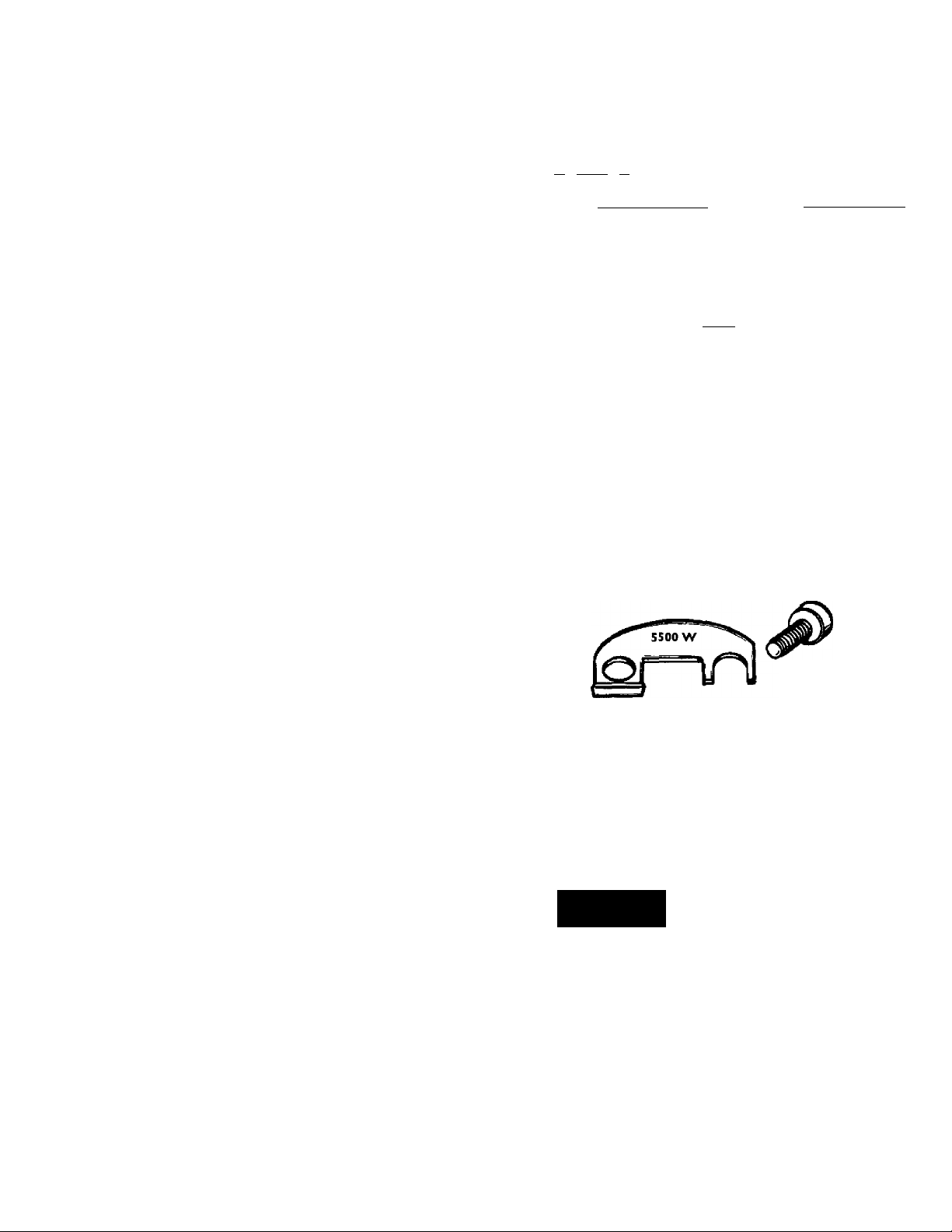
Necessary element conversion parts are located in a small bag
contained within the electrical junction box on top of the water
heater.
CONVERSION PARTS
SCREW
BUSS BAR
The Lower Element of the water heater can he converted from
operation at 3800 watts to 5500 watts on a 240 volt system.
If after reading these instructions and this manual, if you do not
understand any portion, call Sears Service Center.
A WARNING
Before making the conversion to 5500 watts, check the
(I) power supply...must be 240 volts, (2) wiring... 10 gauge
AWG, Type TW, 60“C or equivalent, and (3) Circuit
breakers or fusing...capable of 30 amp loading. Also, the
installation must conform with this Manual, local codes
and electric utility rules. FAILURE TO COMPLY CAN
RESULT IN DEATH, SERIOUS BODILY INJURY OR
PROPERTY DAMAGE.
1. Before beginning the conversion turn “OFF” electric power
supply to the water heater.
IlKlIli
A WARNING
HAZARD OF ELECTRICAL SHOCK! Before removing
any access panels or servicing the water heater, make
sure the electrical supply to the water heater is turned
“OFF”. FAILURE TO DO THIS COULD RESULT IN
DEATH, SERIOUS BODILY INJURY. OR PROPERTY
DAMAGE.
10
 Loading...