

Page 1
Owners
Manual
FOR POTABLE WATER
HEATING ONLY
NOT SUITABLE FOR
SPACE HEATING
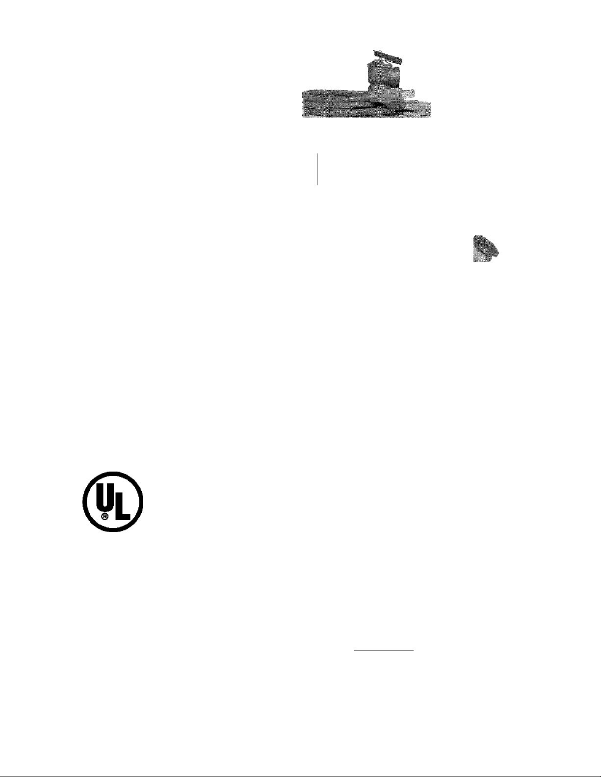
Model No.
153.317020 2 Gal.
IpnttsHM
< '' SbSIEÌIÌI
POINT OF USE
||^|
imoiirf
■
1»
■
m.
LISTED
Caution:
Read and Follow
All Safety Rules and
Operating instructions
Before First Use of
This Product.
Save this Manual for Future Reference.
Sears, Roebuck and Co., Hoffman Estates, IL 60179 U.S.A.
Printed in the U.S.A. 1203
’VVVVTER |^EXVГER
Safety Instructions
Installation
Operation
EFFICIENCY
FiATiNG
CEPTiFiED
G
READ THE GENERAL SAFETY SECTION BEGINNING ON INSIDE COVER
AND THEN THIS ENTIRE MANUAL BEFORE INSTALLING OR OPERAT
ING THIS WATER HEATER.
ama
www.sears.com
GAMA certification applies to all residential electric water heaters with
capacities of 20 to 120 Gallons, input rating of 12 Kw or less at a voltage
no greater than 250 V.
• Care and Maintenance
• Troubleshooting
• Parts List
Awarning
Part No. 184734-000
Page 2

Safety Precautions
A WARNING
Improper installatton, adjustment, alteration, service or
maintenance can cause DEATH, SERIOUS BODILY
INJURY, OR PROPERTY DAMAGE. Refer to this manual
for assistance or consult your local Sears Service Center
for further information.
A WARNING
At the time of manufacture diis v/ater heater was provided with
a combination temperature-pressures relief valve certified by a
nationally recognized testing laboratory that maintains periodic
inspection of production of listed equipment or materials, as
meeting the requirements for Relief Valves :md Automatic Gas
Shutoff Devices for Hot Water Supply Systems, and the current
edition of ANSI Z2I.22 • CSA 4.4 æid the code requirements of
ASME. If replaced, the valve must meet the requirements of
local codes, but not less than a combination temperature <md
pressure relief valve certified as meeting the requirements for
Relief Valves and Automatic Gas Shutoff Dewces for Hot Water
Supply Systems, ANSI Z21.22 • CSA 4.4 by a nationally recog
nized te^ng laboratory that maintains periodic inspection of
production of listed equipment or materials.
The valve must be mariced with a maximum set pressure not
to exceed the marked hydrostatic woriting pressure of the
water heater (ISO lbs./sq. in.) and a discharge edacity not
less than the water heater input rate as shown on the model
rating plate. (Electric heaters - watts divided by lOOO x 3412
equd BTU/Hr. rate.)
Your locid jurisdictional autiiority, while mandating tiie use of a
temperatijre-pressure relief valve complying wth ANSI Z21.22 •
CSA 4.4 and ASME, may require a vidve model different from
the one furnished witii tiie water heater.
Compliance with such local requirements must be satisfied by
the installer or end user of the water heater with a locally pre
scribed temperature-pressure relief valve instidied in the desig
nated opening in the water heater in place of the factory fur
nished valve.
For safe operation of the water heater, the relief valve must not
be removed from it’s designated opening or plugged.
The temperabjre-pressure relief valve must be instidled directly
into the fitting of the water heater designated for tiie relief valve.
Position the valve downward iuid provide tubing so that any dis
charge will exit only within 6 inches <d>ove, or at any distance
below the structural floor. Be certain that no contact is made
^h any live electrical part The discharge opening must not be
blocked or reduced in size under any circumstances. Excessive
length, over 30 feet, or use of more than four elbows can cause
restriction and reduce the discharge capacity of die valve.
No valve or other obstruction is to be placed between the relief
valve and the tank. Do not connect tubing directly to discharge
drain unless a 6" air gap is provided, lb prevent bodily injury, haz
ard to life, or ^operty damage, the relief vdve murt be idlowed
to discharge water in quantities should circumstances demand. If
the discharge pipe is not connected to a drain or other suititie
means, the water flow may cause prqserty dam<^.
The Discharge Pipe:
• Must not be smaller in size than the outlet pipe size of
the valve, or have any reducing couplings or other
restrictions.
• Must not be plugged or blocked.
• Must be of material listed for hot water disdibution.
• Must be installed so as to allow complete drainage of
both the temperature-pressure relief valve, and the dis
charge pipe.
• Must terminate at an adequate dr^n.
• Must not have æiy v^ve betmen the relief valve æid 1ш1к.
A WARNING
HAZARD OF ELECTRICAL SHOCK! Before removing
any access panels or servicing the water heater, make
sure the electrical supply to the water heater is turned
“OFF”. Failure to do this could result in DEATH, SERI
OUS BODILY INJURY, OR PROPERTY DAMAGE.
A WARNING
HOTTER WATER CAN SCALD: Water heaters are
intended to produce hot water. Water heated to a tem
perature which will satisfy space heating, clothes washing,
dish washing, and other sanitizing needs can scald and
permanently injure you upon contact. Some people are
more likely to be permanently injured by hot water than
others. These include the elderly, children, the infirm, or
physically/mentally handicapped. If anyone using hot
water in your home fits into one of these groups or if
there is a local code or state law requiring a certain tem
perature water at the hot water tap, then you must take
special precautions. In addition to using the lowest possi
ble temperature setting that satisfies your hot water
needs, a means such as a mixing valve, shall be used at
the hot water taps used by these people or at the water
heater. Mixing valves are available at plumbing supply or
hardware stores. Follow manufacturers instructions for
installation of the valves. Before changing the factory set
ting on the thermostat, read the “Temperature
Regulation” section in this manual.
A WARNING
WATER HEATERS EQUIPPED FOR ONE VOLTAGE
ONLY: This water heater is equipped for one type voltage
only. Check the rating plate near the bottom access panel
for the correct voltage. DO NOT use this water heater
with any voltage other than the one shown on the model
rating plate. Failure to use the correct voltage can cause
problems which can result in DEATH, SERIOUS BODILY
INJURY, OR PROPERTY DAMAGE. If you have any ques
tions or doubts consult your electric company.
A WARNING
INSULATING JACKETS: When installing an external
water heater insulation jacket on an electric water
heater:
a. DO NOT cover the temperature-pressure relief valve.
b. DO NOT put insulation over the access covers or any
access areas.
c. DO NOT remove operating instructions, and safety
related warning labels and materials affixed to
the water heater.
d. DO obtain new warning and instruction labels from
Sears for placement on the jacket directly over the
existing labels.
A WARNING
Do not use this appliance if any part of it has been under
water. An electrical short or malfunction could occur. The
water heater should be replaced.
A CAUTION
WATER HEATERS EVENTUALLY LEAK: Installation of
the water heater must be accomplished in such a manner
that if the tank or any connections should leak, the flow of
water will not cause damage to the structure. When such
locations cannot be avoided, a suitable drain pan should
be installed under the water heater. Drain pans are avail
able at your local Sears Store. Such a drain pan must be
piped to an adequate drain.
Page 3

Table of Contents
Safety Precautions.............................................................................2
Table of Contents...............................................................................................................................................................3
Customer Responsibilities....................................................................................................................................4
Product Specifications................................................................................................................................................4
Materials and Basic Tools Needed.....................................................5
Materials Needed.......................................................................................................................................................................................5
Basic Tools................................................................................................................................................................................................. 5
Installation Instructions
Removing the Old Water Heater............................................................................................................................................................. 6
Facts to Consider About the Location......................................................................................................................................................7
Optional Wall Mounting.......................................................................................................................................................................7, 8
Witer Piping..............................................................................................................................................................................................8
Temperature-Pressure Relief Valve..........................................................................................................................................................9
Filling the Water Heater.........................................................................................................................................................................10
Optional Cord Set....................................................................................................................................................................................10
Wiring Diagrams..................................................................................................................................................................................... 10
Wiring......................................................................................................................................................................................................11
Installation Checklist...............................................................................................................................................................................12
Service and Adjustment
Temperature Regulation.........................................................................................................................................................................13
Thermostats............................................................................................................................................................................................. 13
Temperature Settings..............................................................................................................................................................................13
Thermostat Adjustment..........................................................................................................................................................................13
Temperature-Pressure Relief Valve Operation......................................................................................................................................14
Draining...................................................................................................................................................................................................14
Element Cleaning/Replacement........................................................................................................................................................15-17
Drain Valve Washer Replacement.........................................................................................................................................................17
Service......................................................................................................................................................................................................17
Troubleshooting Guide
Start Up Conditions.................................................................................................................................................................................18
Thermal Expansion................................................................................................................................................................................18
Strange Sounds.......................................................................................................................................................................................18
Operational Conditions.....................................................................................................................................................................19, 20
Smelly Water.........................................................................................................................................................................................19
“Air” in Hot Water Faucets...................................................................................................................................................................19
Rumbling Noise.....................................................................................................................................................................................19
High Temperature Shut Off System...............................................................................................................................................19, 20
Not Enough or No Hot Water..............................................................................................................................................................20
Water Is Too Hot...................................................................................................................................................................................20
Leakage Checkpoints...............................................................................................................................................................................21
Parts Order List.............................................................................................................................................................22,23
^5(ihrranty...................................................................................................................................................................................24
Page 4

Customer Responsibilities
Thank You for purchasing a Sears water heater.
Properly installed and maintained, it should give you years of
trouble free service. If you should decide that you want the new
water heater professionally installed by Sears call the local
Service Center or any Sears store. They will arrange for prompt,
quality installation by Sears authorized contractors.
Abbreviations Found In This Instruction Manual
U.L. - Underwriters Laboratories Inc., 333 Pfingsten Rd.,
Northbrook, IL 60062
NEC - National Electrical Code
ANSI - American National Standards Institute
• Read the “Safety Precautions” section, page 2 of this manual
first and then the entire manual carefully. If you don’t follow
the safety rules, the water heater will not operate properly. It
could cause DEATH, SERIOUS BODILY INJURY AND/OR
PROPERTY DAMAGE.
This manual contains instructions for the installation, opera
tion, and maintenance of this electric water heater. It also con
tains warnings throughout the manual that you most read and
be aware of All warnings and all instructions are essential to
the proper operation of the water heater and your safety. Since
we cannot put everything on the first few pages, READ THIS
ENTIRE MANUAL BEFORE ATTEMPTING TO
INSTALL OR OPERATE THE WATER HEATER.
The installation must conform with the instructions in this
manual; electric company rules; and Local Codes, or in the
absence of Local Codes, with the current edition of the NEC,
National Electrical Code NFPA 70. 'fhis publication is available
from your local government or public library or electric compa
ny or by writing Underwriters Laboratories Inc., 333 Pfingsten
Road, Northbrook, IL 60062.
If after reading this manual you have any questions or do not
understand any portion of the instructions, call Sears
Service Center.
Carefully plan the place where you are going to put the water
heater. Correct electrical wiring and connections are very
important in preventing death from possible electrical shock
and fires. Examine the location to ensure the water heater com
plies with the “Facts to Consider About the Location” section.
For California installation this water heater must be braced,
anchored, or strapped to avoid falling or moving during an
earthquake. See instructions for correct installation procedures.
Instructions may be obtained from your local dealer, whole
saler, public utilities or California Office of the State Architect,
400 P Street, Sacramento, CA 95814.
Massachusetts Code requires this water heater to be installed
in accordance with Massachusetts 248-CMR 2.00: State
Plumbing Code and 248-CMR 5.00.
Product Specifications
MAXIMUM FUSE
TANK
MODEL
NUMBER
153.317020 2 10" 12%"
*Wiring size based on standard 60°C copper wire. If distance from fuse box to water heater is more than 90 feet, refer to your local elec
trical code.
CAPACITY
IN GALLONS
DIMENSIONS IN INCHES
DIAMETER HEIGHT 120 Volt
RECOVERY RATE
GALS. PER HOUR
@ gOE. RISE
7
ELEMENT
WATTAGE
1440 12 20
MINIMUM
WIRE SIZE*
(GAUGE)
OR CIRCUIT
BREAKER
SIZE (AMPS)
Page 5
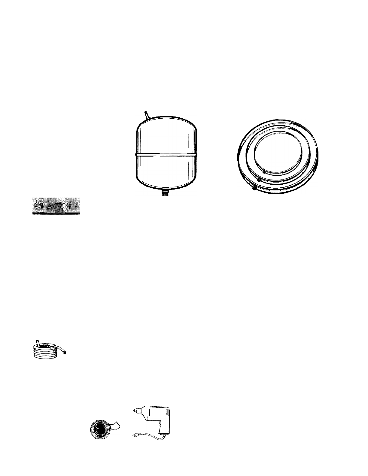
Materials and Basic Tools Needed
Materials Needed
To simplify the installation Sears has available the installation
parts shown below. You may or may not need all of these materi
als, depending on your type of installation.
!§■
'■
■■
li'' ■
EXPANSION TANKS FOR THERMAL
EXPANSION CONDITIONS AVAILABLE
IN 2 GALLON CAPACITY THROUGH
WATER HEATER INSTALLA
TION KIT WITH FLEXIBLE
CONNECTORS FOR 3/4" OR
1/2" THREADED OR COPPER
PLUMBING
LOCAL SEARS SERVICE CENTERS
Basic Tools
You may or may not need all of these tools, depending on your
type of installation. These tools can be purchased at your local
Sears store.
• Pipe Wrench (2) 14"
• Screwdriver
• 6 Foot Tape or Folding Rule
• Garden Hose
• Drill
• Pipe Dope or Teflon Tape
GARDEN HOSE
•
6 FOOT TAPE
SLOT-HEAD SCREWDRIVER
PHILLIPS SCREWDRIVER
PIPE
WRENCH
DRAIN PANS AVAILABLE IN 20"
DIAMETER FOR WATER HEATERS
HAVING A DIAMETER IS" OR LESS,
24" DIAMETER FOR WATER
HEATERS HAVING A DIAMETER 22"
OR LESS AND AVAILABLE IN 28"
DIAMETER FOR WATER HEATERS
HAVING A DIAMETER 26" OR LESS
ADDITIONAL TOOLS NEEDED WHEN SWEAT SOLDERING
• Tubing Cutters or Hacksaw
• Propane Torch
• Soft Solder
• Solder Flux
• Emery Cloth
• Wire Brushes
HACKSAW
3/4” WIRE BRUSH
1/2" WIRE BRUSH
ñ
PIPE DOPE (SQUEEZE TUBE)
(Use only on water connections)
i-oll of teflon t^e DRILL
ROLL OF LEAD FREE
SOFT SOLDER
ROLL OF EMERY
CLOTH
SOLDER
FLUX
PROPANE TORCH
TUBING
CUTTER
Page 6
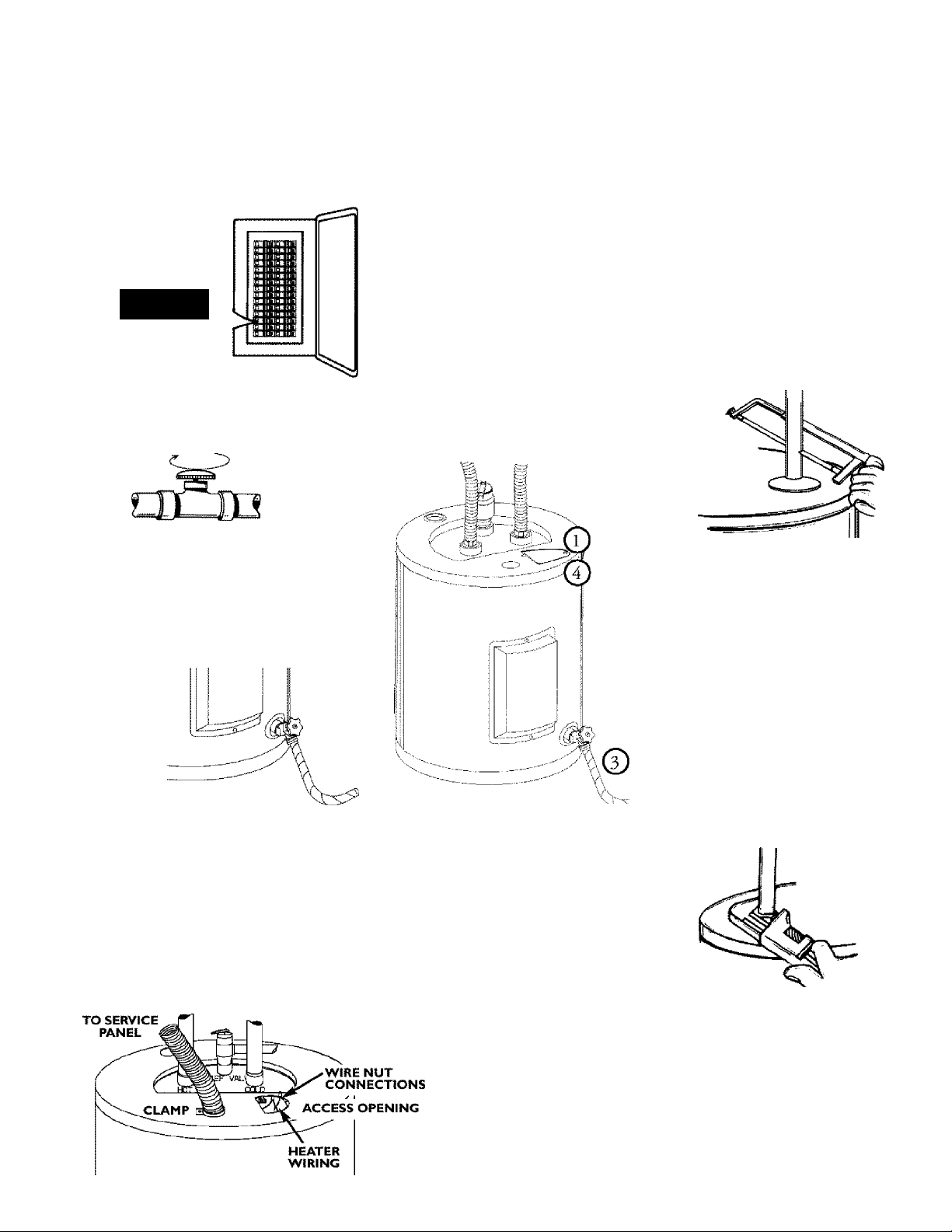
Installation Instructions
Removing the Old Water
Heater
© luFii “OFF” electrical supply to the water heater.
IKIIIIi
© Furn “OFF” the water supply to the water heater at
the water shutoff valve or water meter.
Attach a hose to the water heater drain
valve and put the other end in a floor
drain or outdoors. Open the water heater
drain valve. Open a nearby hot water
faucet which will relieve pressure in the
water heater and speed draining.
[ 5 If yoti have copper piping to the water heater,
the two copper water pipes can be cut with a
hacksaw approximately 4" away from where
they connect to the water heater. This will
avoid cutting off the pipes too short.
Additional cuts can be made later if necessary.
Disconnect the temperature-pressure relief
valve drain line. When the water heater is
drained, disconnect the hose from the drain
valve. Close the drain valve. The water heater
is now completely disconnected and ready to
be removed.
©
b. If you have galvanized pipe to the
water heater, loosen the two gal
vanized pipes with a pipe wrench
at the union in each line. Also
disconnect the piping remaining
to the water heater. These pieces
should be saved since they may be
needed when reconnecting the
new water heater. Disconnect the
temperature-pressure relief valve
drain line. When the water heater
is drained, disconnect the hose
from the drain valve. Close the
drain valve. The water heater is
1-,} now completely disconnected and
ready to be removed.
A WARNING
The water passing out of the drain valve may be extreme
ly hot. To avoid being scalded, make sure all connections
are tight and that the water flow is directed away from
any person.
Check again to make sure the electrical supply is
turned “OFF” to the water heater. Then unplug the
water heater (cord set) or disconnect the electrical sup
ply connection from the water heater junction box.
A CAUTION
Mineral buildup or sediment may have accumulated in the
old water heater. This causes the water heater to be
much heavier than normal and this residue, if spilled out,
could cause staining.
Page 7
Installation Instructions (cont’d)
Facts to Consider About the Location
You should carefully choose an indoor location for the new
water heater, because the placement is a very important consid
eration for the safety of the occupants in the building and for
the most economical use of the appliance. This water heater is
not intended for outdoor installation.
Whether replacing an old water heater or putting the water
heater in a new location, the following critical points must be
observed.
• The location selected should be indoors as close to and as
centralized with the water piping system as possible. This
water heater, as well as all water heaters, will eventually leak.
Do not install without adequate drainage provisions where
water flow will cause damage.
A CAUTION
WATER HEATERS EVENTUALLY LEAK: Installation of
the water heater must be accomplished in such a manner
that if the tank or any connections should leak, the flow of
water will not cause damage to the structure. When such
locations cannot be avoided, a suitable drain pan should
be installed under the water heater. Drain pans are avail
able at your local Sears stores. Such a drain pan must be
piped to an adequate drain.
A CAUTION
INSTALLATION IN RESIDENTIAL GARAGES: The
water heater must be located and/or protected so it is
not subject to physical damage by a moving vehicle.
The location selection must provide adequate clearances for
servicing and proper operation of the water heater.
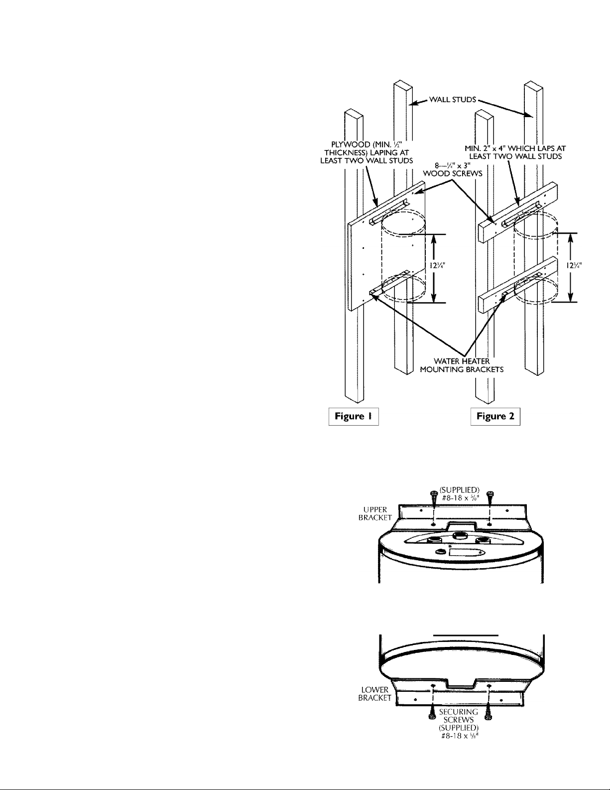
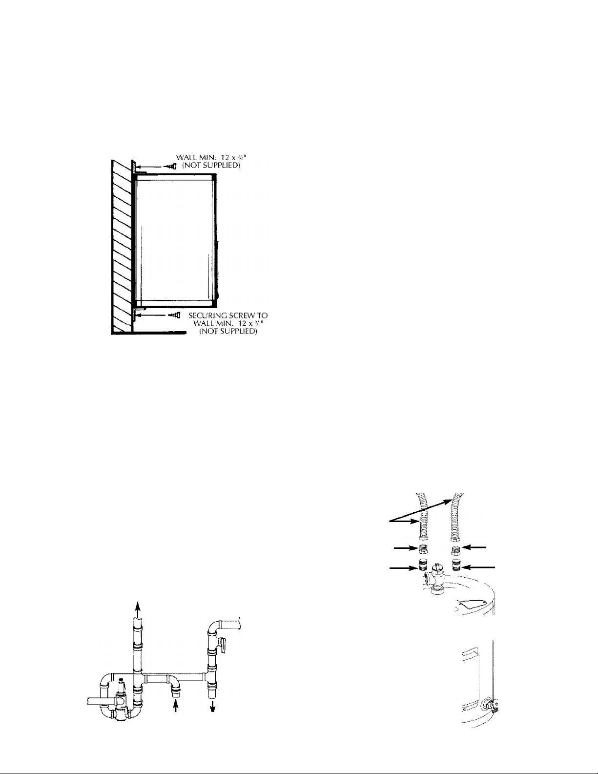
Optional Wall Mounting
A WARNING
Wail construction at the point of the water heater instal
lation must be capable of supporting at least 200 pounds.
As an example: if the water heater is to be installed on a wall of
gypsum board (dry wall) or other material not capable of sup
porting the water heater filled with water, additional bracing will
be necessary. Iwo possibilities are shown below.
1. Using two sheet metal screws supplied, secure the top mount
ing bracket to the top of the water heater.
SECURING SCREWS
2. Using the remaining two sheet metal screws provided, secure
the bottom mounting bracket to the bottom of the water
heater.
Page 8
Installation Instructions (cont’d)
Optional Wall Mounting (conty)
3. Determine the location on the wall, and then the height
above the floor which the wall securing bracket will be
placed. Using adequate screws, or nuts and bolts (not sup
plied) , fasten the wall securing bracket to the wall.
SECURING SCREW TO
Water Piping
’»A WARNING
HOTTER WATER CAN SCALD: Water heaters are intend
ed to produce hot water. Water heated to a temperature
which will satisfy space heating, clothes washing, dish wash
ing, and other sanitizing needs can scald mid permanently
injure you upon contact. Some people are more likely to be
permanently injured by hot water than others. These
include the elderly, children, the infirm, or physically/mentally handicapped. If anyone using hot water in your home
fits into one of these groups or if there is a local code or
state law requiring a certain temperature water at the hot
water tap, then you must take special precautions. In addi
tion to using the lowest possible temperature setting that
satisfies your hot water needs, a means such as a mixing
valve, shall be used at the hot water t^s used by these peo
ple or at the water heater. Mixing valves are available at
plumbing supply or hardware stores. Follow manufacturers
instructions for installation of the valves. Before changing
the factory setting on the thermostat, read the
“Temperature Regulation” section in this mmiual.
If a water heater is installed in a closed water supply system;
such as one having a back-flow preventer, check valve, water
meter with a check valve, etc... in the cold water supply; means
must be provided to control thermal expansion. Contact the
local utility or Sears Service Center on how to control this situation.
The illustration shows the attachment of the water piping to the water
heater. The water heater is equipped with V " water connections.
• Look at the top of the water heater. The hot water outlet is
marked hot. Put two or three turns of teflon tape around the
threaded end of the compression coupling and around the /i"
threads of the
V " x 14" reducer bushing. Put two or three turns of
teflon tape around both ends of a 14" threaded nipple (not sup
plied in the installation kit). Attach the 14" threacled nipple to
the X 14" reducer bushing and screw into the hot water outlet
of the water heater. Using flexible connectors, connect the hot
water pipe to the hot water outlet of the water heater.
NOTE: If using copper tubing, solder tubing to an
adapter before attaching the adapter to the water connec
tions. Do not solder the water supply lines directly to the
connections of the water heater. It will harm the fittings
on the water heater.
• Look at the top of the water heater. The cold water inlet is
marked cold. Put two or three turns of teflon tape around the
threaded end of the compression coupling and around the 14"
threads of the 14" x 14" reducer bushing. Put two or three turns of
teflon tape around both ends of a 14" threaded nipple (not sup
plied in the installation kit). Attach the 14" threaded nipple to
the 14" X 14" reducer bushing and screw into the cold water inlet
of the water heater. Using flexible connectors, connect the hot
water pipe to the hot water outlet of the water heater.
NOTE: Your water heater is insulated to minimize heat
loss from the tank. Further reduction in heat loss can be
accomplished by insulating the hot water lines from the
water heater.
installation COMPLETED using
Installation Kit
^COMPRESSION.
X COUPLING \ WVALVE
HOT OUTLET
TO HOUSE
FLEXIBLE WATER
CONNECTORS
1/2" x3/4" REDUCER
BUSHING
1/2" THREADED
NIPPLE (not supplied .
with installation kit)
_____
COLD INLET
WATER LINE
1/2" x3/4" REDUCER
BUSHING
1/2" THREADED
NIPPLE (not supplied
with installation kit)
TEMPERED
WATER OUTLET
«MIXING VALVE
HOT WATER
OUTLET
I
FROM HOT
WATER OUTLET
ON WATER HEATER
COLD WATER
INLET
TO COLD WATER
INLET ON
WATER HEATER
■
1 DRAIN VALVE
Page 9

Installation Instructions (cont’d)
Temperatu re- Pressu re
Relief Valve
A WARNING
At the time of manufacture this water heater was provided
with a combination temperature-pressures relief valve certi
fied by a nationally recognized testing laboratory that main
tains periodic inspection of production of listed equipment
or materials, as meeting the requirements for Relief Valves
and Automatic Gas Shutoff Devices for Hot Water Supply
Systems, and the current edition of ANSI Z2I.22 * CSA 4.4
and the code requirements of ASME. If replaced, the valve
must meet the requirements of local codes, but not less
than a combination temperature and pressure relief valve
certified as meeting the requirements for Relief Valves and
Automatic Gas Shutoff Devices for Hot Water Supply
Systems, ANSI Z2I.22 • CSA 4.4 by a nationally recognized
testing laboratory that maintains periodic inspection of pro
duction of listed equipment or materials.
The valve must be marked with a maximum set pressure
not to exceed the marked hydrostatic working pressure of
the water heater (ISO lbs./sq. in.) and a discharge capacity
not less than the water heater input rate as shovm on the
model rating plate. (Electric heaters - watts divided by 1000
X 3412 equal BTU/Hr. rate.)
Your local jurisdictional authority, while mandating the use
of a temperature-pressure relief valve complying with ANSI
Z2I.22 • CSA 4.4 and ASME, may require a valve model dif
ferent from the one furnished with the water heater.
Compliance with such local requirements must be satisfied
by the installer or end user of the water heater with a locally
prescribed temperature-pressure relief valve installed in the
designated opening in the water heater in place of the facto
ry furnished valve.
For safe operation of the water heater, the relief valve must
not be removed from it's designated opening or plugged.
The temperature-pressure relief valve must be installed
directly into the fitting of the water heater designated for
the relief valve. Position the valve downward and provide
tubing so that any discharge will exit only within 6 inches
above, or at any distance below the structural floor. Be cer
tain that no contact is made with any live electrical part.
The discharge opening must not be blocked or reduced in
size under any circumstances. Excessive length, over 30 feet,
or use of more than four elbows can cause restriction and
reduce the discharge capacity of the valve.
No valve or other obstruction is to be placed between the
relief valve and the tank. Do not connect tubing directly to
discharge drain unless a 6" air gap is provided. To prevent
bodily injury, hi^ard to life, or property damage, the relief
valve must be allowed to discharge water in quantities
should circumstances demand. If the discharge pipe is not
connected to a drain or other suitable means, the water flow
may cause property damage.
The Dischm'ge Pipe:
• Must not be smaller in size than the outlet pipe size of
the valve, or have any reducing couplings or other
restriction.
• Must not be plugged or blocked.
• Must be of material listed for hot water distribution.
• Must be installed so as to allow complete drainage of
both the temperature-pressure relief valve, and the dis
charge pipe.
• Must terminate at an adequate drain.
• Must not have any valve between the relief valve and tank.
A WARNING
The temperature-pressure relief valve must be manually
operated at least once a year. Caution should be taken to
ensure that ( I ) no one is in front of or around the outlet
of the temperature-pressure relief valve discharge line,
and (2) the water manually discharged will not cause any
bodily injury or property damage because the water may
be extremely hot.
If after manually operating the valve, it fails to completely
reset and continues to release water, immediately, close
the cold water inlet to the water heater, follow the drain
ing instructions, and replace the temperature-pressure
relief valve with a new one.
Page 10

Installation Instructions (cont’d)
Filling the Water Heater Wiring Diagrams
To fill the water heater with water:
• Close the water heater drain valve by turning the handle to
the right (clockwise). The drain valve is located on the lower
fiont of the water heater.
• Open the cold water supply valve to the water heater.
NOTE: The cold water supply valve must be left open
when the water heater is in use.
• To insure complete filling of the tank, allow air to exit by
opening the nearest hot water faucet. Allow water to run
until a constant flow is obtained. This will let air out of the
water heater and the piping.
A CAUTION
Never use this water heater unless it is completely full
of water. To prevent damage to the tank and heating
element, the tank must be filled with water. Water
must flow from the hot water faucet before turning
“ON” power.
Check all new water piping for leaks. Repair as needed-
120 VOLT CORD SET
GREEN
Optional Cord Set Wiring (120 Volt)
There may be a cord set supplied with the water heater at the
time of manufacture, if not one can be ordered through the
Parts Department, see “Repair Parts” section. Refer to figures on
this page for wiring diagrams.
120 VOLT >VIRING
10
Page 11

Installation Instructions (cont’d)
Wiring
____________
Never use this water heater unless it is completely full
of water. To prevent damage to the tank and heating
element, the tank must be filled with water. Water
must flow from the hot water faucet before turning
“ON” power.
You must provide all wiring of the proper size outside of the
water heater. You must obey local codes and electric company
requirements when you install this wiring.
If you are not familiar with electric codes and practices, or if you
have any doubt, even the slightest doubt, in your ability to con
nect the wiring to this water heater, obtain the service of a com
petent electrician. Contact your Sears salesperson to arrange for
a professional electrician.
A CAUTION
______________
A WARNING
WATER HEATERS EQUIPPED FOR ONE VOLTAGE
ONLY: This water heater is equipped for one type volt
age only. Check the rating plate near the bottom
access panel for the correct voltage. DO NOT use this
water heater with any voltage other than the one
shown on the model rating plate. Failure to use the
correct voltage can cause problems which can result in
DEATH, SERIOUS BODILY INJURY, OR PROPERTY
DAMAGE, if you have any questions or doubts consult
your electric company.
^
B. Rigid metal conduit, intermediate metal conduit, or elec
trical metallic tubing may be used for the grounding
means if conduit or tubing is terminated in fittings
approved for grounding.
C. Flexible metal conduit or flexible metallic tubing shall be
permitted for grounding if all the following conditions
are met;
1. The length in any ground return path does not exceed
6 feet.
2. I'he circuit conductors contained therein are protect
ed by overcurrent devices rated at 20 amperes or less.
3. The conduit or tubing is terminated in fittings
approved for grounding. For complete grounding
details and all allowable exceptions, refer to the cur
rent edition of the National Electrical Code, NFPA
70.
4. A standard !4” conduit opening has been made in the
water heater junction box for the conduit connection.
5- Use wire nuts and connect the power supply wiring to
the wires inside the water heater s junction box.
6. I'he water heater must be electrically “grounded” by
the installer. A green ground screw has been provided
on the water heater’s junction box. Connect ground
wire to this location.
7- Replace the wiring junction cover using the screw
provided.
A CAUTION
If wiring from your fuse box or circuit breaker box
was aluminum for your old water heater, replace
it with copper wire. If you wish to reuse the exist
ing aluminum wire, have the connection at the
water heater made by a competent electrician.
Contact your Sears salesperson to arrange for a
professional electrician.
1. Provide a way to easily shut off the electric power when
working on the water heater. I'his could be with a circuit
breaker or fuse block in the entrance box or a separate dis
connect switch.
2. Install and connect a circuit directly from the main fuse or
circuit breaker box. This circuit must be the right size and
have its own fuse or circuit breaker. Refer to the chart in the
“Product Specifications” section for the correct size wire and
fuse or circuit breaker.
3. If metal conduit is used for the grounding conductor:
A. The grounding electrode conductor shall be of copper,
aluminum, or copperclad aluminum. The material shall
be of one continuous length without a splice or joint.
GREEN GROUND SCREW
11
Page 12

Installation Instructions (cont’d)
Installation Checklist
Is the fuse or circuit breaker size correct as shown in the
chart in the “Product Specifications” section?
Are the wires from the circuit breaker or fuse service to the
water heater’s junction box on the correct wire size (gauge)
as shown in the chart in the “Product Specifications” sec
tion?
Is the new temperature-pressure relief valve properly
installed, and piped to an adequate drain? See “TemperaturePressure Relief Valve” section.
Is the water heater completely filled with water? See “Filling
the Water Heater” instructions in the “Installation
Instructions” section.
Will a water leak damage anything? See “Facts to Consider
About the Location” section.
Are the cold and hot water lines connected to the water
heater correctly? See “Water Piping” instructions in the
“Installation Instructions” section.
Is there adequate clearance for maintenance around the
water heater?
Do you need to call your electric company to check your
wiring?
HOT WATER
CONDUIT.
TEMPERATURE-PRESSURE
RELIEF VALVE
SHUT-OFF
«-.VALVE
COLD WATER
DISCHARGE PIPE
(Do not cap or plug.
Provide a 6" air gap
between the end of the
pipe and drain.)
DRAIN VALVE
FLOOR DRAIN
ELEC7BIC \WER HEATER eco
atrom na æiuïR al-
mf» mmm moccl t
FACIÏHWËQUIPeBJWrrM U.S.8«..
UPPâ4 LOME» WJQUM HltOKISTRnC
WATTS WATTS WATTS AC-ONLY rwSTAUJEDAB P.S.».
OPnOttíLWATTtóE F«JT0RVEQt№P60
»« «■ iNSTWxa)
(fc)
ELEMENT MAWAI VOLTS wQMgMi PMMWNe
gSm MAXIMUM
WATTS WATre WATTS F CtWVÇRT^
MODEL RATING PLATE
SE№ALNUIitt6B
150
8€E CONVERSION
INSTRUCTION
12
Page 13

Service and Adjustment
Temperature Regulation Temperature Settings
A WARNING
HOTTER WATER CAN SCALD: Water heaters are
intended to produce hot water. Water heated to a
temperature which will satisfy clothes washing, dish
washing, and other sanitizing needs can scald and per
manently injure you upon contact. Some people are
more likely to be permanently injured by hot water
than others. These include the elderly, children, the
infirm, or physically/mentally handicapped. If anyone
using hot water in your home fits into one of these
groups or if there is a local code or state law requiring
a certain temperature water at the hot water tap,
then you must take special precautions, in addition to
using the lowest possible temperature setting that sat
isfies your hot water needs, some type of tempering
device, such as a mixing valve, should be used at the
hot water taps used by these people or at the water
heater. Mixing valves are available at plumbing supply
or hardware stores. Follow manufacturers instructions
for installation of the valves, Before changing the
factory setting of the thermostat, read the
“Temperature Regulation’’ section in this manual.
A WARNING
Never allow small children to use a hot water tap,
or to draw their own bath water. Never leave a
child or handicapped person unattended in a bath
tub or shower.
Thermostats
A WARNING
This special thermostat with ECO (Part No. 9002394) can
only be used with this water heater. Do not use any other
thermostat with ECO.
The thermostat is factory set at a position which approximates
120°F (Hot) and is adjustable if a different water temperature is
desired. Read all warnings in this manual and on the water
heater before proceeding.
LO— Setting, approximately 95°F, is recommended for vaca
tions or extended periods of no hot water.
HI— Is a setting for the maximum hot water usage approxi
mately 140°F, which can be supplied by the water heater.
The temperature dial should be kept at a lower setting
whenever possible.
NOTE: Water temperature range of 120°—140°F recom
mended by most dishwasher manufacturers.
Time to Produce
2nd & 3rd Degree
Temperature Setting
I60”F About t/2 seconds
IS0”F About t-t/2 seconds
I40'F
I30'F
I20'F
Burns on Adult Skin
Less tiian 5 seconds
About 30 seconds
More than 5 minutes
Thermostat Adjustment
The thermostat is adjustable if a different water temperature is
desired. Read all warnings in the “Temperature Regulation” sec
tion before proceeding.
To adjust the temperature setting;
1. lurn “OFF” the electrical power to the water heater at the
junction box.
The thermostat of this water heater has been factory set at the
mid position which approximates 120°F (Hot) to reduce the risk
of scald injury. The thermostat is adjustable if a different water
temperature is desired. Read all warnings in this manual and on
the water heater before proceeding.
A WARNING
HAZARD OF ELECTRICAL SHOCK! Before
removing any access p^els or servicing the water
heater, make sure the electrical supply to the water
heater is turned "OFF”. Failure to do this could
result in DEATH, SERIOUS BODILY INJURY, OR
PROPERTY DAMAGE.
2. lake off the access panel and fold away the insulation.
3. Turn the water temperature dial clockwise (
increase the temperature, or counter clockwise (
decrease the temperature.
4. Fold the insulation back in place and replace the access panel.
5. llirn “ON” the power supply.
13
Page 14

Service and Adjustment (cont’d)
Temperature-Pressure Relief Draining
Valve Operation
The temperature-pressure relief valve must be man
ually operated at least once a year.
A WARNING
The temperature-pressure relief valve must be manually
operated at least once a year. Caution should be taken to
ensure that (I) no one is in front of or around the outlet
of the temperature-pressure relief valve discharge line,
and (2) the water manually discharged will not cause any
property damage or bodily injury. The water may be
extremely hot.
If after manually operating the valve, it fails to completely
reset and continues to release water, immediately close
the cold water inlet to the water heater, follow the drain
ing instructions, and replace the temperature-pressure
relief valve with a new one.
The water heater should be drained if being shut down during
freezing temperatures. Also periodic draining and cleaning of
sediment from the tank may be necessary.
• Before beginning turn “OFF” the electric power supply to the
water heater.
A WARNING
HAZARD OF ELECTRICAL SHOCK! Before removing
any access panels or servicing the water heater, make
sure the electrical supply to the water heater is turned
“OFF”. Failure to do this could result in DEATH, SERI
OUS BODILY INJURY, OR PROPERTY DAMAGE.
CLOSE the cold water inlet valve to the water heater.
OPEN a nearby hot water faucet and leave open to allow for
draining.
Connect a hose to the drain valve and terminate to an adequate
drain or outdoors.
OPEN the water heater drain valve to allow for tank draining.
NOTE; If the water heater is going to be shut down and
drained for an extended period, the drain valve should be
left open with hose connected allowing water to terminate
to an adequate drain.
Close the drain valve.
Failure to install and maintain a new properly listed temperaturepressure relief valve will release the manufacturer from any claim
which might result from excessive temperature or pressure.
A WARNING
If the temperature-pressure relief valve on the appliance
weeps or discharges periodically, this may be due to ther
mal expansion. Your water heater may have a check
valve installed in the water line or a water meter with a
check valve. Consult your local Sears Service Center for
further information. Do not plug the temperature-pres
sure relief valve.
Follow “Filling the Water Heater” instructions in the
“Installation Instructions” section.
Turn “ON” power to the water heater.
A CAUTION
Never use this water heater unless it is completely full
of water. To prevent damage to the tank and heating
element, the tank must be filled with water. Water
must flow from the hot water faucet before turning
“ON” power.
___________________________________________
14
Page 15

Service and Adjustment (cont’d)
Element Cleaning/ Replacement
To remove the element from your tank in order to clean or
replace it;
1. Before beginning turn “OFF” the electric power supply to the
water heater.
A WARNING
HAZARD OF ELECTRICAL SHOCK! Before
removing any access panels or servicing the water
heater, make sure the electrical supply to the water
heater is turned "OFF”. Failure to do this could
result in DEATH, SERIOUS BODILY INJURY, OR
PROPERTY DAMAGE.
A WARNING
The water passing out of the drain valve may be
extremely hot. To avoid being scalded, make sure all
connections are tight and that the water flow is
directed away from any person.
4. Remove the two screws securing the access panel, and remove
panel.
5- Open the flap of insulation to expose the opening.
2. I'urn off the water supply to the water heater at the water
shutoff valve or water meter.
3. Attach a hose to the water heater drain valve and put the
other end in a floor drain or outdoors. Open the water heater
drain valve. Open a nearby hot water faucet which will relieve
pressure in the water heater and speed draining.
6. Lift out the tab as shown to unclip the terminal cover from
the thermostat. The terminal cover can now be removed
from the thermostat.
15
Page 16

Service and Adjustment (cont’d)
Element Cleaning/ Replacement (cont’d)
7. Disconnect the two wires on the element and unscrew the
old element firom the tank.
8. Clean the area around the element opening. Remove any
sediment from or around the element opening, inside the
tank.
9. If you are cleaning the element you have removed, do so by
scraping or soaking in vinegar or a de-liming solution.
A WARNING
Replacement elements must (I) be the same volt
age and (2) no greater wattage than listed on the
model rating plate affixed to the water heater.
12. Open the cold water supply valve to the water heater.
NOTE: The cold, water supply valve must be left open
when the water heater is in use.
13- To insure complete filling of the tank, allow air to exit by
opening the nearest hot water faucet. Allow water to run
until a constant flow is obtained. This will let air out of the
water heater and the piping.
A CAUTION
Never use this water heater unless it is completely
full of water. To prevent damage to the tank and
heating element, the tank must be filled with water.
Water must flow from the hot water faucet before
turning “ON” power.
14. Check element for water leaks, if leakage occurs, tighten
element or repeat steps 2 and 3, remove element and reposi
tion gasket. Then repeat steps 10 through 14.
15. Reconnect the two wires to the element and then check to
make sure the thermostat remains firmly against the surface
of the tank.
10. A new gasket should be used in all cases to prevent a possible
water leak. (See Element Gasket in the “Parts Order List”
Chart). Place the new element gasket on the thread side of
the cleaned or new element and screw into tank, securing
tightly using an element wrench.
11. Close the water heater drain valve by turning the handle to
the right (clockwise). The drain valve is on the lower front
of the water heater.
16. Replace terminal cover on thermostat and fold insulation
back over the element.
16
Page 17

Service and Adjustment (cont’d)
Drain Valve Washer Replacement
17. Fold the insulation back in place so that it completely covers
the thermostat and element.
18- Replace access panel.
19- Turn “ON” electric power to water heater.
NOTE: For replacement, ase a ‘%2" x x ‘/s" thick washer
available at year nearest hardware store. For ordering a
replacement washer, refer to the “Parts Order List” section.
• Before beginning turn “OFF” the electrical power supply to
the water heater.
A WARNING
HAZARD OF ELECTRICAL SHOCK! Before
removing any access p^els or servicing the water
heater, make sure the electrical supply to the water
heater is turned "OFF”. Failure to do this could
result in DEATH, SERIOUS BODILY INJURY, OR
PROPERTY DAMAGE.
Follow “Draining” instructions in the “Service and
Adjustment” section.
I'urning counter clockwise, remove the hex cap below the
screw handle.
Remove the washer and put the new one in place.
Screw the handle and cap assembly back into the drain valve
and retighten using a wrench. DO NOT OVER TIGHTEN.
Follow “Filling the Water Heater” instructions in the
“Installation Instructions” section.
A CAUTION
Never use this water heater unless it is completely
full of water. To prevent damage to the tank and
heating element, the tank must be filled with water.
Water must flow from the hot water faucet before
turning “ON” power.
Check for leaks.
Turn “ON” electric power to the water heater.
Service
Before calling for repair service, read the “Start Up Conditions”
and “Operational Conditions” found in the Troubleshooting
Guide of this manual.
If a condition persists or you are uncertain about the operation
of the water heater, let a qualified person check it out.
Contact SEARS Repair Services at 1-800-4-MY-HOME
(1-800-469-4663)
17
Page 18

Troubleshooting Guide
Start Up Conditions
THERMAL EXPANSION
Water supply systems may, because of such events as high line
pressure, frequent cut-offs, the effects of water hammer among
others, have installed devices such as pressure reducing valves,
check valves, back flow preventers, etc...to control these types of
problems. When these devices are not equipped with an internal
by-pass, and no other measures are taken, the devices cause the
water system to be closed. As water is heated, it expands (ther
mal expansion) and closed systems do not allow for the expan
sion of heated water.
The water within the water heater tank expands as it is heated and
increases the pressure of the water system. If the relieving point of
the water heater's temperature-pressure relief valve is reached, the
valve will relieve the excess pressure. The temperature-pressure
relief valve is not intended for the constant relief of thermal
expansion. This is an unacceptable condition and must be cor
rected.
It is recommended that any devices installed which could create a
closed system have a by-pass and/or the system have an expan
sion tank to relieve the pressure built by thermal expansion.
Thermal expansion tanks are available from Sears stores and
through the Sears Service Centers. Contact the local plumbing
inspector, water supplier and/or the Sears Service Center for
assistance in controlling these situations.
WATER HEATER
COtO WATER
iNLET FrrriNG
FLOOR, CEiLING
JOIST, ETC.
Thermal Expansion Tank Specifications
Model
Number
153.331020
Tank Capacity
In Gallons
2
Dimensions in Inches Pipe Fitting
Diameter Length
8 inches 1214 inches
On Tank
y;’ Male
Expansion Tank Sizing Chart
Expansion
Tank
Capacity
Needed
*Highest recorded inlet water pressure in a 24 hour period or
regulated water pressure.
NOTE: Expansion tanks are pre-charged with a 40 psi air
charge. If the inlet water pressure is higher than 40 psi, the
expansion tank’s air pressure must be adjusted to match that
pressure, but most not be higher than 80 psi.
Inlet*
Water
Pressure
40-80psi 2 2 2 2 2
Water Heater Capacity (Gallons)
2 4
6
10
19.9
(3)
PRESSURE
REDUCING INLET COLD
VALVE WITH WATER
BY-RftSS SHUTOFF
I
/
PRESSURE GAUGE
ALTERNATE RECOMMENDED
INSTALLATION
(HORIZONTAL MOUNTING)
STRANGE SOUNDS
Possible noises due to expansion and contraction of some metal
parts during periods of heat-up and cool-down do not represent
harmful or dangerous conditions.
18
Page 19

Troubleshooting Guide
Operational Conditions
SMELLY WATER
In each water heater there is installed an anode rod for corrosion
protection of the tank. Certain water conditions will cause a
reaction between this rod and the water. I'he most common
complaint associated with the anode rod is one of a “rotten egg
smell”. This odor is derived from hydrogen sulfide gas dissolved
in the water. I'he smell is the result of four factors which must
all be present for the odor to develop:
a. a concentration of sulfate in the supply water.
b. little or no dissolved oxygen in the water.
c. a sulfate reducing bacteria within the water heater. (This
harmless bacteria is non-toxic to humans.)
d. an excess of active hydrogen in the tank. This is caused by
the corrosion protective action of the anode.
The anode rod in a new glasslined water heater works rapidly to
protect the tank. After a period of time the anode action slows
and the odor may dissipate.
A smelly water condition (Rotten Egg Odor) in your Point of
Use water heater can, in most cases, he resolved or reduced with
the addition of sufficient amounts of chlorine to eliminate the
bacterial growth inside the tank. This can be accomplished
through the installation of a chlorine feeder to the system or the
periodic flushing of the water heater with “Chlorox” as neededOn systems where the odor is mild and does not occur too
rapidly, a monthly flushing may be sufficient. In more severe
cases, a system feeder would be more appropriate.
RUMBLING NOISE
In some water areas, scale or mineral deposits will build up on
your heating elements- This buildup will cause a rumbling noise.
Follow “Element Cleaning/Replacement” instructions to clean
and replace the elements.
HIGH TEMPERATURE SHUT OFF SYSTEM
The water heater has a high limit shut off system with a reset
button located on the thermostat.
Follow the resetting instructions which refer to the high limit
behind the access panel.
• Before beginning, turn “OFF” electrical power supply to the
water heater.
"AIR” IN HOT WATER FAUCETS
A WARNING
HYDROGEN GAS: Hydrogen gas can be produced In a
hot water system that has not been used for a long period
of time (generally two weeks or more). Hydrogen gas is
extremely flammable and explosive. To prevent the possi
bility of infury under these conditions, we recommend the
hot water faucet be opened for several minutes at the
kitchen sink before any electrical appliances which are
connected to the hot water system are used (such as a
dishwasher or washing machine). If hydrogen gas is pre
sent, there will probably be an unusual sound similar to
air escaping through the pipe as the hot water faucet is
opened. There must be no smoking or open flame near
the faucet at the time it is open.
A WARNING
HAZARD OF ELECTRICAL SHOCK! Before removing
any access panels or servicing the water heater, make
sure the electrical supply to the water heater is turned
“OFF”. Failure to do this could result in DEATH, SERI
OUS BODILY INJURY, OR PROPERTY DAMAGE.
19
Page 20

Troubleshooting Guide (cont’d)
HIGH TEMPERATURE SHUT OFF SYSTEM
(cont’d)
• Remove the two screws securing the access panel and remove
panel.
• Open the flap of insulation to expose the opening.
• Reset the high limit by pushing in the red button marked
“RESET”.
■RESET BUTTON
• Fold the insulation back in place so that it completely covers
the thermostat and element.
• Replace the access panel.
• Turn “ON” electric power to the water heater.
NOT ENOUGH OR NO HOT WATER
• In a new installation, the water heater may not be properly
connected. Make sure the cold water supply valve is open.
Review and check piping installation. Make sure that the
cold water line is connected to the cold water inlet to the
water heater and the hot water line to the hot water outlet
on the water heater.
• Make sure the electrical supply to your water heater is
“ON”.
• Check for loose or blown fuses in your water heater circuit.
Circuit breakers weaken with age and may not handle their
rated load and should be replaced.
• Make certain the disconnect switch, if used, is in the “ON”
position.
• Check to see the electric service to your house has not been
interrupted. If this is the case, contact the electric company.
• Is the thermostat set to the desired temperature? See
“Temperature Regulation” section.
• If you had experienced very hot water and now no hot
water, the problem may be due to the high temperature
shut off system. See “High Temperature Shut Off System”
in the “I'roubleshooting” section.
• During very cold weather, the incoming water will also be
colder and it will require a longer time to become heated.
A CAUTION
If the high limit must be reset again, call Sears Service
Department to find out why the high limit turned “OFF”
the electric power.
• The hot water usage may exceed the capacity of the water
heater. If so, wait for water heater to recover after abnormal
demand. Also examine pipes and faucets for possible water
leaks.
• If you can not determine the problem, then call the Sears
Service Department.
WATER IS TOO HOT
Adjust the thermostat to a lower setting. See the “Temperature
Regulation” section.
20
Page 21

Troubleshooting guide (cont’d)
Leakage Checkpoints
Use this guide to check a “Leaking” water heater. Many suspected
“Leakers’ are not leaking tanks. Often the source of the water
can be found and corrected.
If you are not thoroughly familiar with electric codes, the water
heater, and safety practices, contact a Sears Service Center to
check the water heater.
Read this manual first. Then before checking the
water heater m^e sure the electric supply has been
turned “OFF”, and never turn the electric supply
“ON” before the t^k is completely full of water.
Condensation may be seen on pipes in humid weather
or pipe connections may be leaking.
A CAUTION
®
©
Small amounts of water from the temperature-pressure
relief valve may be due to thermal expansion or high
water pressure in your area.
*^The temperature-pressure relief valve may be leaking at
the tank fitting.
The element may be leaking at the tank fitting.
A WARNING
HAZARD OF ELECTRICAL SHOCK! Before
removing any access panels or servicing the
water heater, make sure the electrical supply
to the water heater is turned “OFF”. Failure
to do this could result in DEATH, SERIOUS
BODILY INJURY, OR PROPERTY DAMAGE.
Turn electrical power “OFF”, remove access panel and
fold back insulation. If leaking around element, follow
proper draining instructions and remove element.
Reposition or replace gasket on element. Place element
into opening and tighten securely. Then follow “Filling
the Water Heater” instructions in the “Installation
Instructions” section.
Water from drain valve may be due to the valve being
opened slightly.
*The drain valve may be leaking at the tank fitting.
*Water in the water heater bottom or on the floor may
be from condensation, loose connections or the temper
ature-pressure relief valve. DO NOT replace the water
heater until a full inspection of all possible water
sources is made and necessary corrective steps taken.
21
Leakage from other appliances, water lines, or ground
seepage should also be checked.
NOTE; To check where threaded portion enters
tank, insert cotton swab between jacket opening and
fitting. If cotton is wet, follow “Draining” instruc
tions in tke “Service and Adjustment” section and
then remove fitting. Put pipe dope or teflon tape on
the threads and replace. Then follow “Filling the
Water Heater” instructions in the “Installation
Instructions” section.
Page 22

Parts Order List
KENMORE POINT OF USE ELECTRIC WATER HEATER
MODEL NUMBER:
153.317020 2 Gai.
fT
22
Page 23

Parts Order List (cont’d)
KENMORE POINT OF USE ELECTRIC WATER HEATER
MODEL NUMBER:
153.317020 2 Gal.
MODEL NUMBERS
KEY PART 153.317020
NO.
DESCRIPTION
1. Temperature-Pressure Relief Valve
2. Dip Tube & Gasket
Drain Valve 9002402
3.
4. Drain Valve Washer ('752*’ x ’/¿i" x !4" thick)* 9001584
Element Gasket 9000308
5.
Element
6.
Thermostat Bracket
7.
Thermostat w/Hi Limit 9002394
8.
Terminal Cover 9002438
9.
10. Access Panel
11. Wiring Bushing 9001514
12.
Cord Set — 120 Volt
Mounting Brackets
13.
14. function Box Cover 9001474
Model Rating Platef 0270182
15.
# Manual 184734-000
PART NUMBERS
9000071
9002396
9001511
9000309
9001472
9001513
9001512
*Also available at most hardware stores.
tReplaced only on return of damaged plate.
#Not Illustrated
Now that you have purchased your Water Heater, should a need ever exist for repair parts or service, simply contact any SEARS Service
Center or call 1-800-4-MY-HOME (1-800-469-4663). Be sure to provide all pertinent facts when you call or visit.
All parts listed may be ordered from any SEARS Service Center, most SEARS stores, and by calling 1-800-366-PART (1-800-366-7278).
If the parts you need are not stocked locally, your order will be electronically transmitted to a SEARS Repair Parts Distribution Center for
handling
The model number of the water heater will be found on the model rating plate located beside the access panel.
WHEN ORDERING REPAIR PARTS, ALWAYS GIVE THE FOLLOWING INFORMATION:
MODEL NUMBER NAME OF ITEM
PART NUMBER PART DESCRIPTION
THIS IS A REPAIR PARTS LIST, NOT A PACKING LIST.
23
Page 24

FULL 90 DAY WARRANTY ON WATER HEATER
For 90 days from the date of purchase, when your Sears Kenmore water heater is installed and operated in a single-family residence
in accordance with the instructions in this manual, Sears will;
1. Repair defects in material or workmanship in this water heater, free of charge.
2. Furnish and Install a new current model water heater of equal capacity and quality, free of charge, if a leak occurs in the tank.
LIMITED WARRANTY ON TANKS THAT LEAK
After 90 days and through I year from the date of purchase for a water heater used in a single-family residence, if a leak occurs in
the tank. Sears will furnish a new current model water heater of equal capacity and quality. You will be charged for any
installation.
To obtain warranty service, SIMPLY CALL I-800-4-MY-HOME* (1-800-469-4663). This warranty applies only while this
product is in use in the United States.
This warranty gives you specific legal rights and you may also have other rights which vary from state to state.
SEARS. ROEBUCK AND CO„ Dept. 817 WA, HOFFMAN E.STAl'E.S, II. 60179
The price of your water heater does not include a free checkup service call. On water heater installations arranged by Sears, Sears warrants the installation.
A charge will be made on service calls due to poor or incomplete installation. These include:
a. Adjusting thermostat b. Leaks in pipes or fittings c. Condensation
MASTER PROTECTION AGREEMENTS
Congratulations on making a smart purchase. Your new Kenmore® prod
uct is designed and manufactured for years of dependable operation. But
like all products, it may require preventive maintenance or repair from
time to time. Tbats when having a Master Protection Agreement can
save you money and a^ravation.
Purchase a Master Protection Agreement now and protect yourself from
unexpected hassle and expense.
The Master Protection Agreement also helps extend the life of your new
product. Here’s whats included in the Agreement:
• Expert Service by our 12,000 professional repair specialists.
• Unlimited service and no charge for parts and labor on all covered
repairs.
• “No-lemon” guarantee - replacement of your covered product if four
or more product failures occur within twelve months.
• Product replacement if your covered product can’t be fixed.
• Annual Preventive Maintenance Check at your request - no extra
charge.
For in*home major brand repair service
Call 24 hours a day, 7 days a week (U.S.A. and Canada)
• Fast help by phone - phone support from a Sears technician on
products requiring in-home repair, plus convenient repair scheduling.
• Power surge protection against electrical damage due to power fluc
tuations.
• Rental reimbursement if repair of your covered product takes longer
than promised.
Once you purchase the Agreement, a simple phone call is all that it takes
for you to schedule service. You can call anytime day or night, or sched
ule a service appointment on-line.
Sears has over 12,000 professional repair specialists, who have access to
over 4.5 million quality parts and accessories. That’s the kind of profes
sionalism you can count on to help prolong the life of your new purchase
for years to come. Purchase your Master Protection Agreement today!
Some limitations and exclusions apply. For prices and additional
information call l'800-827'6655
SEARS INSTALLATION SERVICE
For Sears professional installation of home appliances, garage door open
ers, water heaters and other major home items, in the U.S.A., call
1-800-4-MY-HOME*.
I-800-4-MY-HOME®
(1-800-469.4663)
www.se^rs.com
The model number of your water heater is found on the model rating plate on the front of the water heater.
Sears, Roebuck and Co., Hoffman Estates, IL 60179 U.S.A.
 Loading...