

Kenmore 153313640, 153313442, 153313340, 153313240 Owner’s Manual
Owners
Manual
FOR POTABLEWATER
HEATING ONLY
NOT SUITABLEFOR
SPACEHEATING
Model No.
153.313240 40 Gat.Short
153.313340 30 Gal.
153.313442 40 Gal.
153.313640 50 Gal.
THE ECONOMIZER TM6
LISTED
Caution:
Read and Follow
All Safety Rules and
Operating Instructions
Before First Use of
This Product.
Save this Manual for Future Reference.
ELECTRIC
WATER HEATER
• Safety Instructions
• Installation
• Operation
GAMA certification applies to all residential electric water heaters with
capacitiesof 20 to 120 Gallons. Inputrating of 12Kw or lessat avoltage
no greater than 250 _L
READ THE GENERAL SAFETY SECTION BEGINNING ON INSIDE COVER
AND THEN THIS ENTIRE HANUAL BEFORE INSTALLING OR OPERAT-
ING THIS WATER HEATER.
• Care and Maintenance
• Troubleshooting
• Parts List
_WARNING
Sears, Roebuck and Co., Hoffman Estates, IL 60179 U.S.A.
Printed in the U.S.A. 1203 www.sears.com Part No. 184708*000
Safety Precautions
_,WARNING J
Improper installation, adjustment, alteration, service or
maintenancecan causeDEATH, SERIOUSBODILY INJURY,J
OR PROPERTY DAMAGE. Refer to this manual for assis-
tance or consult your localSearsServiceCenter for further
information.
_WARNING
At the time of manufacture this water heater was provided
with a combination temperature*pressures relief valve certi-
fied by a nationally recognized testing laboratory that main-
tains periodic inspection of production of listed equipment or
materials, as meeting the requirements for Relief Valves and
Automatic Gas Shutoff Devices for Hot Water Supply
Systems, and the current edition of ANSI Z21.22 • CSA 4.4
and the code requirements of ASME. If replaced, the valve
must meet the requirements of local codes, but not lessthan a
combination temperature and pressure relief valve certified as
meeting the requirements for Relief Valves and Automatic
Gas Shutoff Devices for Hot Water Supply Systems, ANSI
Z21.22 • CSA 4.4 by a nationally recognized testing laboratory
that maintains periodic inspection of production of listed
equipment or materials.
The valve must be marked with a maximum set pressure not
to exceed the marked hydrostatic working pressure of the
water heater (150 Ibs. p.s.i.) and a dischargecapacity not less
than the water heater input rate as shown on the model rating
plate. (Electric heaters - watts divided by 1000 x 3412 equal
BTU/Hr. rate.)
Your localjurisdictional authority, while mandating the use of
a temperature-pressure relief valve complying with ANSI
Z21.22 • CSA 4.4 and ASME, may require a valve model differ-
ent from the one furnished with the water heater.
Compliance with such local requirements must be satisfied by
the installer or end user of the water heater with a locallypre-
scribed temperature-pressure relief valve installed in the des-
ignated opening in the water heater in place of the factory fur-
nishedvalve.
For safe operation of the water heater, the relief valve must
not be removed from it's designated opening or plugged.
The temperature-pressure relief valve must be installed
directly into the fitting of the water heater designated for the
relief valve. Position the valve downward and provide tubing so
that any discharge will exit only within 6 inches above, or at
any distancebelow the structural floor. Be certain that no con-
tact is made with any live electrical part. The dischargeopen-
ing must not be blocked or reduced in size under any circum-
stances. Excessive length, over 30 feet, or use of more than
four elbows can cause restriction and reduce the discharge
capacity of the valve.
No valve or other obstruction is to be placed between the
relief valve and the tank. Do not connect tubing directly to dis-
charge drain unlessa 6" air gap isprovided. To prevent bodily
injury, hazard to life, or property damage, the relief valve must
be allowed to discharge water in quantities should circum-
stances demand. If the discharge pipe is not connected to a
drain or other suitable means, the water flow may causeprep-
erty damage.
The Discharge Pipe:
• Must not be smaller in size than the outlet pipe size of the
valve, or haveany reducing couplingsor other restrictions.
• Must not be pluggedor blocked.
• Must beof material listed for hot water distribution.
• Must be installed so as to allow complete drainage of both
the temperature-pressure relief valve, and the discharge
pipe.
• Must terminate at an adequate drain.
• Must not have any valve between the relief valve and tank.
_,WARNING J
HAZARD OF ELECTRICAL SHOCK! Before removing
any access panels or servicing the water heater, make J
sure the electrical supply to the water heater isturned
"OFF". Failure to do this could result in DEATH, SERI-
OUS BOD LY NJURY,OR PROPERTY DAMAGE.
AWARNING
HOTTER WATER CAN SCALD: Water heaters are
intended to produce hot water. Water heated to a tem-
perature which will satisfyspaceheating,clotheswashing,
dish washing, and other sanitizing needs can scald and
_ermanently injure you upon contact. Some people are
more likelyto be permanently injured by hot water than
others. These includethe elderly, children, the infirm, or
physically/mentally handicapped. If anyone using hot
water in your home fits into one of these groups or if
there isa localcode or state law requiring a certain tem-
perature water at the hot water tap, then you must take
specialprecautions.In addition to using the lowest possi-
ble temperature setting that satisfies your hot water
needs, a means such as a mixing valve, shall be used at
the hot water taps used by these people or at the water
heater. Mixing valves are available at plumbing supplyor
hardware stores. Follow manufacturers instructions for
installationofthe valves.Before changingthe factory set-
ting on the thermostat, read the "Temperature
Regulation"sectionin this manual.
&WARNING
WATER HEATERS EQUIPPED FOR ONE VOLTAGE
ONLY: This water heater is equipped for one type voltage
only. Check the rating plate near the bottom access panel
for the correct voltage. DO NOT use this water heater
with any voltage other than the one shown on the model
rating plate. Failure to use the correct voltage can cause
problems which can result in DEATH, SERIOUS BODILY
INJURY, OR PROPERTY DAMAGE. If you have any ques-
tions or doubts consult your electric company.
&WARNING
INSULATING JACKETS: When installing an external
water heater insulation jacket on an electric water
heater:
a. DO NOT cover the temperature-pressure relief valve.
b. DO NOT put insulation over the access covers or any
access areas.
c. DO NOT remove operating instructions, and safety
related warning labels and materials affixed to the water
heater.
d. DO obtain new warning and instruction labels from
Sears for placement on the jacket directly over the exist-
in_ labels.
_,WARNING J
Do not usethis appliance if anypart of it hasbeen under J
water. An electrical short or malfunction could occur.The
water heater shoudbe rep aced.
CAUTION
WATER HEATERS EVENTUALLY LEAK: Installation of
the water heater must be accomplished in such a manner
that if the tank or any connections should leak, the flow of
water will not cause damage to the structure. When such
locations cannot be avoided, a suitable drain pan should
be installed under the water heater. Drain pans are avail-
able at your local Sears Store. Such a drain pan must be
piped to an adequate drain.
2
Table of Contents
Safety Precautions ............................................................................................................................................2
Table of Contents ......................................................................................................................................3
Customer Responsibilities ...................................................................................................................4
Product Spedfications ...............................................................................................................................4
Materials and Basic Tools Needed .....................................................................................5
Materials Needed ...................................................................................................................................................................... 5
Basic "lbols ................................................................................................................................................................................ 5
Installation Instructions ....................................................................................................................6-12
Removing the Old Water Heater. ............................................................................................................................................ .6
Facts m Consider About the Location ..................................................................................................................................... .7
Water Piping ............................................................................................................................................................................ .8
T&P Valve and Pipe Insulation .............................................................................................................................................. .8
"l_mperature-Pressure Relief Valve ............................................................................................................................................ .9
Filling the Water Hearer .......................................................................................................................................................... 10
Wiring Diagram ..................................................................................................................................................................... 10
Wiring .............................................................................................................................................................................. 10-11
Installation Checklist .............................................................................................................................................................. 12
Service and Adjustment ...................................................................................................................13-17
"l_mperature Regulation .......................................................................................................................................................... 13
Thermostats ............................................................................................................................................................................ 13
"l_mperature Settings .............................................................................................................................................................. 13
Thermostat Adjustment .......................................................................................................................................................... 13
"lhnperature-Pressure Rdief Valve Operation .......................................................................................................................... 14
Draining ................................................................................................................................................................................. 14
Element Cleaning/Replacement ......................................................................................................................................... 15-17
Anode Rod Inspection ............................................................................................................................................................ 17
Drain Valve Washer Replacement ........................................................................................................................................... 17
Service .................................................................................................................................................................................... 17
Troubleshooting Guide .............................................................................................................. 18-21
Start Up Conditions ............................................................................................................................................................... 18
Thermal Expansion ............................................................................................................................................................... 18
Strange Sounds ..................................................................................................................................................................... 18
Operational Conditions ..................................................................................................................................................... 19-20
Smelly Water ......................................................................................................................................................................... 19
"Air" In Hot Water Faucets .................................................................................................................................................. 19
Rumbling Noise .................................................................................................................................................................... 19
High "Ihnperature Shut Off System ...................................................................................................................................... 19
Not Enough or No Hot XX&rer............................................................................................................................................. 2.0
Water Is _Ibo Hot ................................................................................................................................................................. 2.0
Leakage Checkpoints ............................................................................................................................................................. 2.1
Parts Order List............................................................................................................................................ 22-23
Warranty.. .....................................................................................................................................................................24
Customer Responsibilities
Thank You for purchasing a Sears water heater.
Properly installed and maintained, it should give you years of
trouble free service. If you should decide that you want the new
water heater professionally installed by Sears call the local Sears
Service Center or any Sears store. They will arrange for prompt,
quality installation by Sears authorized contractors.
Abbreviations Found In This Instruction Manual
U.L. - UnderwritersLaboratories Inc.
NEC - National ElectricalCode
ANSI - American National Standards Institute
• Read the "Safety Precautions" section, page 2 of this manual
first and then the entire manual carefully, lfyou don't follow
the safety rules, the water heater will not operate properly.
It could cause DEATH, SERIOUS BODILY INJURY
AND/OR PROPERTY DAMAGE.
This manual contains instructions for the installation, operation,
and maintenance of this electric water heater. It also contains
warnings throughout the manual that you must read and
be aware of. All warnings and all instructions are essential
to the proper operation of the water heater and your safety.
Since we cannot put everything on the first few pages,
READ THIS ENTIRE MANUAL BEFORE
ATTEMPTING TO INSTALL OR OPERATE THE
WATER HEATER.
• The installation must conform with the instructions in this
manual; electric, company rules; and Local Codes, or in the
absence of Local Codes, with the current edition of the
NEC, National Electrical Code, NFPA 70. This publication is
available from your local government or public library or elec-
tric company or by writing Underwriters Laboratories Inc.,
333 Pfingsten Road, Nortbbrook, 1L60062.
• If after reading this manual you have any questions or do not
understand any portion of the instructions, call Sears Service
Center.
• Carefully plan the place where you are going to put the water
heater. Correct electrical wiring and connections are very
important in preventing death from possible electrical shock
and fires.
Examine the location to ensure the water heater complies with
the "Facts to Consider About the Location" section.
• For California installation this water heater must be braced,
anchored, or strapped to avoid falling or moving during an
earthquake. See instructions for correct installation
procedures. Instructions may be obtained from your local
dealer, wholesaler, public utilities or California office of the
State Architect, 400 P Street, Sacramento, CA 95814.
• Massachusetts Code requires this water heater to be installed
in accordance with Massachusetts 248-CMR 2.00: State
Plumbing Code and 248-CMR 5.00.
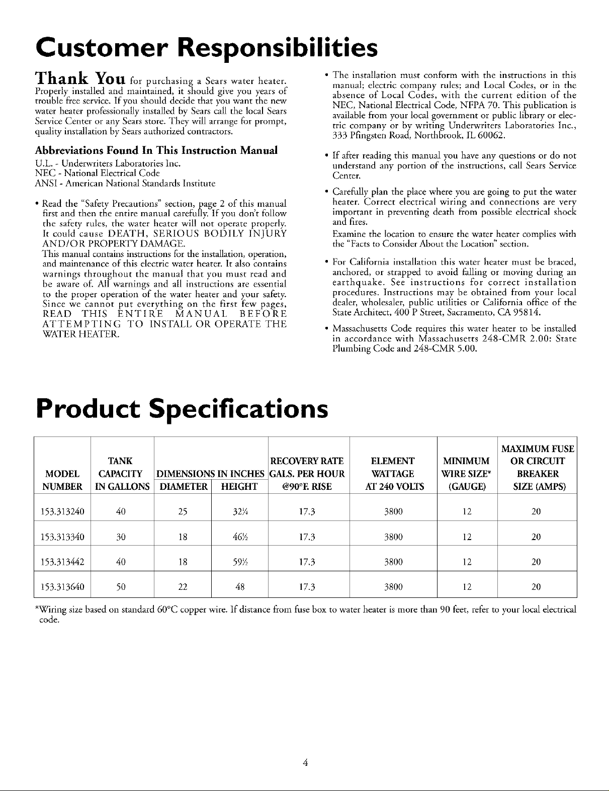
Product Specifications
MAXIMUM FUSE
TANK
MODEL
NUMBER
153.313240
153.313340
153.313442
153.313640
CAPACITY
IN GAI&ONS
40
30
40
50
DIMENSIONS IN INCHES
DIAMETER HEIGHT
25 32¼
18 46B
18 59B
22 48
*Wiring size based on standard 60°C copper wire. If distance from fuse box to water heater is more than 90 feet, refer to your local electrical
code.
RECOVERY RATE
GALS. PER HOUR
@90°E RISE
17.3
17.3
17.3
17.3
ELEMENT
WATTAGE
AT 240VOLTS
3800
3800
3800
3800
MINIMUM
WIRE SIZE*
(GAUGE)
12
12
12
12
OR CIRCUIT
BREAKER
SIZE (AMPS)
20
20
20
20
4

Materials and Basic Tools Needed
Materials Needed
_b simplify the installation Sears has available the installation
_artsshown below. You may or may not need all of these materi-
als, depending on your type of installation.
EXPANSION TANKS FOR THERMAL
EXPANSION CONDITIONS AVAILABLE
IN 2 GALLON AND 5 GALLON CAPACITY
THROUGH LOCAL SEARS STORE OR
SERVICE CENTER
Basic Tools
You may or may not need all of these tools, depending on your
type of installation. These tools can be purchased at your local
Sears store.
Pipe Wrench (2)
Screwdriver
6 Foot Tape or Folding Rule
Garden Hose
Drill
Pipe Dope or Teflon Tape
GARDEN HOSE
SLOT-HEAD SCREW DRIVER
PHILLIPS SCREWDRIVER
6 FOOT TAPE
PIPE
WRENCH
DRAIN PANS AVAILABLE IN 20"
DIAMETER FOR WATER HEATERS
HAVING A DIAMETER 18" OR LESS,
24" DIAMETER FOR WATER
HEATERS HAVING A DIAMETER 22"
OR LESS AND AVAILABLE IN 28"
DIAMETER FOR WATER HEATERS
HAVING A DIAMETER 26" OR LESS
ADDITIONAL TOOLS NEEDED
WHEN SWEAT SOLDERING
•Tubing Cutters or Hacksaw
•Propane Torch
•Soft Solder
•Solder Flux
• Emery Cloth
•Wire Brushes
HACKSAW
3/4" WIRE BRUSH
I/2" WIRE BRUSH
PROPANE TORCH
ROLL OF LEAD FREE
SOFT SOLDER
PIPE DOPE
(SQUEEZE TUBE)
(Use only on water connections)
ROLL OF TEFLON TAPE DRILL
ROLL OF EMERY SOLDER TUBING
CLOTH FLUX CUTTER

Installation Instructions
Removing the Old Water
Heater
Q'Ihrn "OFF" electrical supply to the water heater.
]
©
QTurn "OFF" the water supply to the
water heater at the water shutoffvalve or
water nleter.
If you have copper piping to the water
a,
heater, the two copper water pipes can be
cut with a hacksaw approximately 4" away
from where they connect to the water
heater. This will avoid cutting off the pipes
too short. Additional cuts can be made
later if necessary. Disconnect the tempera-
ture-pressure relief valve drain line. When
the water heater is drained, disconnect the
hose from the drain valve. Close the drain
valve. The water heater is now completely
disconnected and ready to be removed.
Q Attach a hose to the water heater drain
valve and put the other end in a floor
drain or outdoors. Open the water heater
drain valve. Open a nearby hot water
faucet which will relieve pressure in the
water heater and speed draining.
. _ /_ _1 water heater is now completely disconnect-
_,WARNING I
The water passingout ofthe drainvalvemay beextreme- I
ly hot. To avoid being scalded,make sure all connectionsI
are tight and that the water flow is directed away from
any person.
Q Check again to make sure the electrical supply is
turned "OFF" to the water heater. Then disconnect
the electrical supply connection from the water
heater junction box.
Q b. If have galvanized pipe to the water
• drained, disconnect the hose from the
Mineral buildupor sere accumulated inthe I
old water heater. This causes the water heater to be I
much heavierthan normal and this residue, if spilledout, I
couldcausestaining. ]
you
heater, loosen the two galvanized pipes
with a pipe wrench at the union in each
line. Also disconnect the piping remaining
to the water heater. These pieces should be
saved since they may be needed when
reconnecting the new water heater.
Disconnect the temperature-pressure relief
valve drain line. When the water heater is
drain valve. Close the drain valve. The
ed and ready to be removed.
_i CAUTION
l
6
Installation Instructions (cont'd)
Facts to Consider About
the Location
You should carefully choose an indoor location for the new
water heater, because the placement is a very important consid-
eration for the safety of the occupants in the building and for
the most economical use of the appliance. This water heater is
not intended for outdoor installation.
Whether replacing an old water heater or putting the water
heater in a new location, the following critical points must he
observed.
• The location selected should be indoors as close to and as
centralized with the water piping system as possible. This
water heater, as well as all water heaters, will eventually leak.
Do not install without adequate drainage provisions where
water flow will cause damage.
CAUTION
WATER HEATERS EVENTUALLY LEAK: Installation of
the water heater must be accomplished in such a manner
that if the tank or any connections should leak, the flow of
water will not cause damage to the structure. When such
locations cannot be avoided, a suitable drain pan should
be installed under the water heater. Drain pans are avail-
able at your local Sears stores. Such a drain pan must be
piped to an adequate drain.
CAUTION
INSTALLATION IN RESIDENTIAL GARAGES: The I
water heater must be located and/or protected so it is
not subject to phys ca damage by a mov ng veh c e.
• The location selection must provide adequate clearances for
servicing and proper operation of the water heater.
7

Installation Instructions (cont'd)
Water Piping
*A WARNING
HOTTER WATER CAN SCALD: Water heaters are
intended to produce hot water. Water heated to a tem-
perature which will satisfyspaceheating,clotheswashing,
dish washing, and other sanitizing needs can scald and
_ermanently injure you upon contact. Some people are
more likelyto be permanently injured by hot water than
others. These includethe elderly, children, the infirm, or
physically/mentally handicapped. If anyone using hot
water in your home fits into one of these groups or if
there isa localcode or state law requiring a certain tem-
perature water at the hot water tap, then you must take
specialprecautions.In addition to using the lowest possi-
ble temperature setting that satisfies your hot water
needs,a means such as a mixing valve, shall be used at
the hot water taps used by these people or at the water
heater. Mixing valves are available at plumbing supplyor
hardware stores. Follow manufacturers instructions for
installationofthe valves.Before changingthe factory set-
ring on the thermostat, read the "Temperature
Regulation"sectioninthis manual.
HOT WATER A
COLD WATER
_ IN,LET
Installation completed using
Installation Kit
FLEXIBLE
WATER
CONNECTORS
HOT OUTLET
TO HOUSE /
THREADED TO
SWEAT COUPLING
3/4" THREADED_i_ _i_ _ 3/4" THREADED
NIPPLE _ NIPPLE
THREADED TO
SWEAT COUPLING
j TEMPERATURE.
SHUT-OFF
VALVE
WATER LINE
COLD INLET
PRESSURE
RELIEF VALVE
TEMPERED
WATER OUTLET_
_fO COLD WATER
INLET ON
*MIXING VALVE WATER OUTLET
ON WATER HEATER
WATER HEATER
The illustration shows the attachment of the water piping to the
water heater. The water heater is equipped with g" water connec-
tions.
If a water heater is installed in a closed water supply system;such as
one having a back-flow preventer, check valve, water meter with a
check valve, etc. in the cold water supply; means shallbe provided to
control thermal expansion. Contact the local utility or SearsService
Center on how to control this situation.
NOTE: If using copper tubing, solder tubing to an adapter
before attaching the adapter to the cold water inlet connection.
Do not solder the cold water supply line directly to the cold
water inlet. It wRl harm the dip tube and damage the tank.
• Look at the top coverof the water heater. The hot water outlet is
marked hot. Put two or three turns of teflon tape around the
threaded end of the threaded-to-sweat coupling and around both
ends of the _" dlreaded nipple. Using flexible connectors, connect
the hot water pipe to the hot water outlet of the water heater.
• Look at the top cover of the water heater. The cold water inlet is
marked cold. Put two or three turns of teflon tape around the
threaded end of the threaded-to-sweat coupling and around both
ends of the _" threaded nipple. Using flexible connectors, connect
the cold water pipe to the cold water inlet of the water heater.
NOTE: Yourwater heater is insulated to minimize heat loss from
the tank. Further reduction in heat loss can be accomplished by
insulating the hot waterlines from the water heater.
-- DISCHARGE PIPE
(Do not cap or plug)
-_" AIR GAP
FLOOR DRAIN
T&P Valve and Pipe Insulation
Remove insulation forT&P Valveandpipe connections from carton.
Fit pipe insulation over the incoming cold water line and the hot
water line. Make sure that the insula-
tion is against the top cover of the
heater.
Fit T&P Valve insulation over valve.
Make sure that the insulation does
not interfere with the lever of the
T&P valve.
Secureall insulation using tape.
 Loading...